
Abstract
Cavity polaritons derived from strong light–matter interaction provide a basis for efficient manipulation of quantum states via cavity field. Polaritons with narrow linewidth and long lifetime are appealing in applications, such as quantum sensing and storage. Here, we propose a prototypical arrangement to implement a whispering-gallery-mode resonator with one-dimensional topological atom mirror, which allows to boost the lifetime of cavity polaritons over an order of magnitude. This considerable enhancement attributes to the coupling of polaritonic states to dissipationless edge states protected by the topological bandgap of atom mirror that suppresses the leakage of cavity modes. When exceeding the width of Rabi splitting, topological bandgap can further reduce the dissipation from polaritonic states to bulk states, giving arise to subradiant cavity polaritons with extremely sharp linewidth. The resultant Rabi oscillation experiences decay rate lower than the free-space decay of a single quantum emitter. Inheriting from the topologically protected properties of edge states, the subradiance of cavity polaritons can be preserved in disordered atom mirror with moderate perturbations involving the atomic frequency, interaction strengths and location fluctuations. Our work opens up a new paradigm of topology-engineered quantum states with robust quantum coherence for future applications in quantum computing and network.
Export citation and abstract BibTeX RIS

Original content from this work may be used under the terms of the Creative Commons Attribution 4.0 license. Any further distribution of this work must maintain attribution to the author(s) and the title of the work, journal citation and DOI.
1. Introduction
Cavity quantum electrodynamics (QED) constitutes one of the cornerstones of quantum optics, where the coherent exchange of single photon between the quantum emitter (QE) and the cavity mode, known as Rabi oscillation, can take place in the strong-coupling regime and results in the formation of polaritonic states consisting of entangled atom and photon components [1, 2]. The corresponding bosonic quasiparticle, termed cavity polaritons, offers a scheme for controllable storage and transfer of quantum states. A rich variety of technologies and applications based on cavity polaritons have been proposed, such as on-chip quantum light source [3, 4], quantum sensing [5, 6], scalable quantum computing and quantum information processing [2, 7–9]. Great effort has been devoted into achieving strong coupling in various QED platforms [10–14], while less attention is paid to reduce the linewidth of cavity polaritons [15–18], which is beneficial for diverse quantum-optics applications [19–25]. For instance, reducing the linewidth of resonant systems enables to detect weak signals and achieves better measurement sensitivity for precision sensing in experiments [23–28]. Moreover, linewidth represents decay rate, thereby quantum states with narrower linewidth means longer lifetime, a feature highly desirable for quantum storage and quantum memory [29–33]. However, the lifetime of cavity polaritons is often limited by the quality (Q) factor of cavity, since the linewidth of QE is usually smaller than that of cavity in many cavity-QED systems [11, 13, 34, 35]. Besides, a high-Q cavity in general features a large volume [36–38] or requires sophisticated design [39, 40] that is demanding for nanofabrication.
Over the past decade, topological quantum optics arises from the connection of topological physics and quantum optics and serves as a new strategy to control the light–matter interaction in many-body quantum systems by exploiting the concept of topology [41–54]. In analogy to photonic topological insulators, the emergence of exotic topological states in quantum systems, characterized by localized edge states and interface states, demonstrates intriguing optical response and has motivated the development of functional quantum devices with robustness against the structural disorder and impurities, such as topological single-photon circulator [55], topologically protected qubits [43, 46, 56], unconventional photon transport [48, 50, 57], fault-tolerant topological quantum computing [58–60], to mention a few. Among these topological quantum systems, atom arrays can serve as a versatile platform for topological light manipulation, with functionalities beyond the classical mirror that reflects the light [43, 45, 61, 62]. In particular, topological quantum states can become subradiant through the collective interference [43, 45, 56], whose radiative loss can be strongly suppressed and significantly smaller than the free-space decay rate of a single atom. This unique feature of atom arrays combined with topological protection provides extra degrees of freedom to manipulate the quantum dynamics.
Triggered by the prospect of manipulating cavity polaritons through topological effects, we propose a topological edge states-engineered cavity QED system consisting of a whispering-gallery-mode (WGM) resonator coupled to a one-dimensional (1D) topological atom mirror with waveguide-mediated long-range hoppings. With sufficiently strong atom-waveguide coupling, edge states become dissipationless through topological phase transition [47]. By virtue of the exponential localization and topological protection of dissipationless edge states, this simple configuration enables unprecedented linewidth narrowing and decay suppression of polaritonic states using small atom array. Compared with the models in previous studies where only one of the polaritonic states can be bound [20, 49, 63, 64], our work shows that all polaritonic states can be subradiant or bound simultaneously with the help of topological atom mirror. By analyzing the energy spectrum and spectral properties of the composed system, we predict that typically a dozen atoms are adequate to produce subradiance for cavity polaritons and the resultant subnatural linewidth can be experimentally evidenced from either the reflection spectrum of waveguide or the fluorescence of QE. Our scheme can provide a viable approach to realize the long-time storage of quantum states in QED systems with cavities of moderate Q factor and explore the topological manipulation of quantum states on integrated optoelectronic platform.
2. Results and discussion
2.1. Model and theory
The system under investigation comprises of a hybrid cavity QED system based on a WGM ring resonator and a waveguide QED system [65], as figure 1(a) depicts. We choose such a setup for three reasons: (1) The coupled QE-WGM cavity is a relatively mature system for realizing the Jaynes–Cummings model [1] in nanophotonic platform, which is easy to fabricate using the electron beam lithography in experiments [66–68]; (2) It is more efficient to collect the spectrum directionally through a side-coupled bus waveguide than through the scattering of a bare cavity; (3) A topological atom mirror in waveguide instead of on the surface of cavity can avoid the problem of matching the unit cells in topological mirror with the mode profile of cavity in order to achieve efficient coupling. Therefore, our setup is experimentally feasible and is beneficial to unravel the role of topology in manipulating quantum states. Although the ring resonator supports a series of WGM resonances, only a pair of degenerate clockwise (CW) and counterclockwise (CCW) modes with the same WGM order is considered in our model. This simplification is reasonable for a realistic WGM resonator operated in the visible and near-infrared regions, where the linewidth of QE can be much smaller than the free spectral range [21, 34, 69, 70]. A QE is embedded inside the resonator, which is coupled to a waveguide with a topological atom mirror at the right end. The nearest-neighbor interactions between topological atoms change alternately to form 1D diatomic chain in mimicking the Su–Schrieffer–Heeger (SSH) model [41, 71], accompanied by the long-range interactions mediated by waveguide. An extended cascaded quantum master equation is derived in the appendix A.1 and employed to describe the quantum dynamics of the composed system

with Lindblad operator
where the first line introduces the dissipation for individuals, the second line describes the waveguide-mediated interaction between atoms, and the third (four) line accounts for the chiral coupling between the atoms and the CCW (CW) mode through the right-propagating (left-propagating) guided mode of the waveguide. ![$\mathcal{L}[O] \rho = 2 O \rho O^{\dagger}-O^{\dagger} O \rho-\rho O^{\dagger} O$](https://content.cld.iop.org/journals/2058-9565/9/3/035019/revision2/qstad3f46ieqn10.gif) is the Liouvillian superoperator for the dissipation of operator O.
is the Liouvillian superoperator for the dissipation of operator O.  (
( ) is the bosonic annihilation operator of CCW (CW) mode, while κR
(κL
) is the corresponding decay rate stemming from the evanescent coupling to the waveguide. The intrinsic decay of cavity modes is omitted in consideration of the high-Q feature of WGM resonators.
) is the bosonic annihilation operator of CCW (CW) mode, while κR
(κL
) is the corresponding decay rate stemming from the evanescent coupling to the waveguide. The intrinsic decay of cavity modes is omitted in consideration of the high-Q feature of WGM resonators.  is the wave vector of photons.
  is the lowering operator of the jth atom located at xj
and particularly, j = 0 represents the atom inside the cavity, which is referred to as QE hereafter to distinguish from the atoms in the mirror. N and x0 denote the number of atoms and the location of waveguide-cavity junction, respectively. γ0 and γλ
(
is the lowering operator of the jth atom located at xj
and particularly, j = 0 represents the atom inside the cavity, which is referred to as QE hereafter to distinguish from the atoms in the mirror. N and x0 denote the number of atoms and the location of waveguide-cavity junction, respectively. γ0 and γλ
( ) stand for the free-space decay and the waveguide-induced decay of atoms, respectively. Throughout the paper, we consider symmetric coupling of atoms (
 ) and cavity modes (
 ) to two chiral guided modes of waveguide. Meanwhile, the coherent interaction between atoms can be tailored by adjusting the atom spacing [72, 73]. Without loss of generality, we focus on the case of equal atom spacing, i.e.
  for
for  ; the impact of unequal atom spacing is investigated in section 2.3. As we show in the subsequent derivation, the change of atomic spacing solely influences the phase factor φj
of jth atom (see equation (9) for definition), which serves as an independent parameter in the equations governing the dynamics of each atom, thus does not render the validity of equations derived in the main text. With rotating-wave approximation, the total Hamiltonian H of the composed system reads
; the impact of unequal atom spacing is investigated in section 2.3. As we show in the subsequent derivation, the change of atomic spacing solely influences the phase factor φj
of jth atom (see equation (9) for definition), which serves as an independent parameter in the equations governing the dynamics of each atom, thus does not render the validity of equations derived in the main text. With rotating-wave approximation, the total Hamiltonian H of the composed system reads

with the free Hamiltonian

and the interaction Hamiltonian for cavity QED system

and the Hamiltonian describing the coherent coupling between adjacent atoms [44, 47, 74]
where ωc
is the frequency of cavity modes, which resonantly couples to QE with strength g. ωj
is the transition frequency of the jth atom and we assume  unless specially noted. The staggered hoppings
  (
( ) for an odd (even) j result in the dimerized interactions between atoms (see schematic presented in figure 1(a)). Explicitly, the staggered hoppings can be written as
 ![$J_\pm = J_0 [1\pm\mathrm{cos}(\phi)]$](https://content.cld.iop.org/journals/2058-9565/9/3/035019/revision2/qstad3f46ieqn23.gif) , with J0 and φ being the interaction strength and the tunable parameter of dimerization strength that control the bandgap and localization of edge states, respectively. In the absence of dimerized interactions (J0 = 0), the band structure of the atom mirror is topologically trivial, which is centrosymmetric with respect to
, with J0 and φ being the interaction strength and the tunable parameter of dimerization strength that control the bandgap and localization of edge states, respectively. In the absence of dimerized interactions (J0 = 0), the band structure of the atom mirror is topologically trivial, which is centrosymmetric with respect to  and plotted in the inset of figure 1(a). The band structure is modified by the dimerized interactions and gives rise to localized edge states in the strong topological regime with
  , which exhibits the periodicity of
  in d. The inset of figure 1(a) also plots the band structure of topological atom mirror with an odd number of atoms and
  . It shows that a single edge state survives and is isolating from the bulk states due to the presence of energy gap. It also shows that the edge state is exactly protected from the waveguide-mediated interaction for two special values of atom separation,
  and
and  (indicated by the vertical dashed line in the inset of figure 1(a)), where the coupling between topological atoms is fully dispersive [72, 73] but no energy shift is observed. This protection stems from the chiral symmetry of SSH chain; however, the topological phases of
  and
and  are distinct [47]: the former is dissipative while the latter becomes dissipationless when
  where topological phase transition occurs and the decay of edge state is reduced to zero. More discussion on topological phase transition can be found in the appendix A.3. Hereafter, atom mirrors with and without the dimerized interactions (i.e. J0 = 0) are called the topological and trivial atom mirrors, respectively, their interaction with the polaritonic states of strong-coupling cavity QED system yields the topological and non-topological cavity polaritons. In the following study, we consider the Bragg reflection condition
  for trivial atom mirror since it corresponds to the highest reflectivity and hence the greatest lifetime enhancement of cavity polaritons in this setup. While for topological atom mirror, we focus on the case of
  , where the dissipationless edge state with suppressed decay can produce prominent anisotropic scattering of photon [48], as figure 7(f) shows. Furthermore, we consider an odd N since the topological atom mirror with an even N gives rise to two edge states with opposite polarization [57]. It results in the significant reduction of reflectivity compared to that with an odd N, as figure 1(c) shows. The results of figures 1(b) and (c) also indicate that N = 31 is sufficient to reach the maximal reflectivity for
  . In this work, we show that the coupling of cavity QED system to the dissipationless edge state can suppress the cavity dissipation and results in significant linewidth narrowing of cavity polaritons in both weak- and strong-coupling regimes.
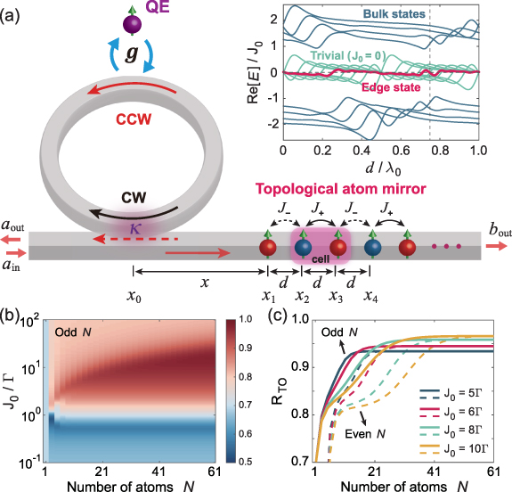
Figure 1. Schematic of the proposed model. (a) Schematic of a ring cavity coupled to a quantum emitter (QE) and a waveguide with a one-dimensional topological atom mirror at the right end. xj
indicates the location of the jth element. The staggered hoppings between nearest-neighbor sites in topological atom mirror simulate the Su–Schrieffer–Heeger (SSH) chain that supports the topological edge states. The pair of sites with stronger coupling defines a unit cell, as the pink translucent box indicates ( ). The inset shows the real energy spectrum of topological atom mirror versus atom spacing d for nine atoms. Vertical dashed line indicates the dissipationless topological edge state at
  under investigation.
  and
and  ,
,  stand for the input and output fields for planewave excitation, respectively. (b) Reflection of topological atom mirror
  versus the number of atoms N and interaction strength J0. (c)
  versus odd (solid lines) and even (dashed lines) N for various J0. Other parameters are
  , φ1 = 0 and
  .
.
Download figure:
Standard image High-resolution imageWe consider the case of a single excitation in the composed system, where the subradiant single-photon states hold a great promise for applications related to quantum memory and quantum information storage [29, 31]. To better understand how the topological edge state affects the quantum dynamics and photon transport, we derive the effective Hamiltonian from equations (1)–(6) under the open boundary condition for atom mirror, which is given by

with the non-Hermitian free Hamiltonian

and the virtual-photon interaction Hamiltonian accounting for the waveguide-mediated long-range hoppings
where the first and second lines characterize the nonlocal interactions between atoms and between the cavity modes and the atoms, respectively.  is the effective phase of light propagating from the waveguide-cavity junction to the jth atom, where
  . Due to the open boundaries of the system, we directly diagonalize
  to obtain the single-photon band structure (the eigenvalues E and the corresponding eigenstates V, i.e.
  ). For the case of N = 31 atoms, figure 2(a) displays the probability distributions of all eigenstates, which are indexed as
  by increasingly sorting the decay rates (i.e.
 ![$-\mathrm{Im}[E]$](https://content.cld.iop.org/journals/2058-9565/9/3/035019/revision2/qstad3f46ieqn41.gif) , the imaginary parts of eigenenergies E) versus system components, including the QE and two cavity modes of cavity QED system and the dimer cells of topological atom mirror. A remarkable feature is that the probability presents a substantial atom content for most of the eigenstates, while concentrates in the cavity QED system for eigenstates labelled
, the imaginary parts of eigenenergies E) versus system components, including the QE and two cavity modes of cavity QED system and the dimer cells of topological atom mirror. A remarkable feature is that the probability presents a substantial atom content for most of the eigenstates, while concentrates in the cavity QED system for eigenstates labelled  and
and  , i.e. the first two eigenstates with smallest decay rate and the last three with fastest decay. The eigenenergies shown in figure 2(b) reveal that the first two eigenstates are essentially the same as the cavity polaritons of bare cavity QED system (i.e. without the atom mirror), but their decay rates are significantly reduced by over an order of magnitude and even smaller than the free-space decay rate γ0 of QE, referred to subradiant cavity polaritons. On the contrary, the subradiance cannot be generated for a non-topological cavity polaritons and its decay rate is nearly triple to the topological one.

Figure 2. Probability distributions and energy spectrum of topological edge states-engineered cavity polaritons. (a) Probability distributions of the composed system. Color of each eigenstate gives the decay rate (imaginary eigenenergy). (b) Complex eigenenergies for cavity QED system with topological (blue circles) and trivial atom mirrors (blue dots). The horizontal dashed line indicates the subradiant region and the vertical green thick lines label the polaritonic states. Complex eigenenergies of bare cavity QED system is also shown for comparison (pink squares), which corresponds to the right axis. (c) Decay rate of topological cavity polaritons  versus odd N for various J0. The results of cavity polaritons with trivial atom mirror (
 ) and perfect classical mirror (i.e. with unity reflectivity, see [20] for the model in detail) are shown for comparison. The inset shows
  for various κ as a function of J0. (d) Probability distributions of topological edge state-engineered cavity polaritons [
 in (a)] and trivial cavity polaritons. Dashed black curve is exponential fits to the probability of cavity polaritons versus cells index. Parameters not mentioned are
  ,
,  ,
,  ,
,  , N = 31, φ1 = 0 and
  . J0 = 0 and
  for trivial atom mirror.
Download figure:
Standard image High-resolution imageFigure 2(c) compares the decay rates of topological and non-topological cavity polaritons versus the number of atom N. It shows that the non-topological cavity polaritons has the advantage of slow decay with a few atoms; however, the decay rate of topological cavity polaritons rapidly drops with increased N and becomes smaller than that of non-topological cavity polaritons with around 10 atoms. For  , 21 atoms are sufficient to reduce the decay rate of topological cavity polaritons to the minimum, and this minimum value is stable as the atom number increases. While the decay rate of non-topological cavity polaritons gradually increases after an optimal N due to the accumulated loss in the system. Figure 2(c) also indicates that there exists an optimal interaction strength
  , denoted as
  , corresponding to the smallest decay rate of topological cavity polaritons, which is about
  , a half of the decay rate of a bare atom. It implies that the reduced decay is achieved by suppressing the dissipation of cavity modes, since on resonance the decay rate of cavity polaritons is the average of atom and photon components. Therefore, cavity polaritons can acquire permanent coherence with a QE whose free-space decay vanishes (i.e. γ0 = 0). This claim is confirmed by the results presented in the inset of figure 2(c), where it shows that in such a case, the decay of topological cavity polaritons can be completely suppressed for different κ. It reveals the formation of bound cavity polaritons in a fully open architecture, which is not found with a trivial atom mirror and cannot be interpreted as a result of classical destructive interference, since the reflectivity of trivial atom mirror at
  is even higher than the topological atom mirror at
  while the lifetime enhancement of the latter is greater, see the figures 7(e) and (f) of appendix A.3. The results indicate that two requirements of atom mirror should be satisfied to produce significant lifetime enhancement of cavity polaritons: one is to have high reflectivity and the other is that the quantum states resonant with cavity QED system are subradiant. As we show in figure 7(f), the highest reflectivity of non-topological atom mirror corresponds to the Bragg reflection condition, however, in this case all quantum states of non-topological atom mirror are resonant with cavity QED system, see the inset of figure 1(a), where one of them is superradiant with decay rate
  . Therefore, the non-topological atom mirror only satisfies one of the requirements and the non-topological cavity polaritons cannot be bound. While for topological cavity, comparable high reflectivity can be achieved at
  since it corresponds to the dissipationless topological phase. At the same time, the edge state undergoes topological phase transition and becomes subradiant when
  . We can see that the topological atom mirror meets both requirements for significant enhancement of lifetime, where the existence of dissipationless topological phase plays a key role in achieving high reflectivity and forming a subradiant edge state.
Besides the decay rate, the probability distributions of non-topological and topological cavity polaritons are also distinct, as figure 2(d) shows. For non-topological cavity polaritons, the probability is uniformly distributed at each cell of atom mirror due to the translational symmetry of homogeneous chain, while localizes at the left boundary for topological cavity polaritons with  and converges to zero after 10 cells. Furthermore, the probability distributions of topological cavity polaritons manifest the behavior of exponential decay from the left boundary, except for the first two cells since the chiral symmetry is broken in our model. These features indicate the formation of edge state in topological atom mirror and its efficient coupling to the cavity QED system, which are the foundation to realize the topology-engineered cavity polaritons. Similar phenomena are also observed for
  , but the probability distribution is less concentrated and extended closer to the right boundary with a slow decay. The strong delocalization of probability distributions for a large J0 is a consequence of waveguide-mediated long-range hoppings between topological atoms [48, 57, 75]. The delocalization tends to populate all topological atoms and leads to the significant decline of reflectivity when J0 exceeds a critical value where the probability is extended to the last cell of topological atom mirror, as illustrated in figure 7(b) of appendix A.3. As a result, the delocalization weakens the ability of topological atom mirror in suppressing the leakage of cavity modes. In this situation, more atoms are required to hinder the extension of probability to the right boundary and reduce the decay of topological cavity polaritons. On the other hand, figure 2(c) also shows the increased decay of topological cavity polaritons for a small J0. It is attributed to the coupling of topological cavity polaritons to bulk states and yields
  for the minimum decay, which we will discuss in the later part of this work.
2.2. Linewidth narrowing and the enhanced lifetime of subradiant cavity polaritons
The subradiance of topological cavity polaritons enables to enhance the quantum coherence, demonstrating the features of slow population decay and linewidth narrowing in spectrum. To investigate the quantum dynamics, we derive the equations of motion from the extended cascaded quantum master equation (equations (1)–(6))


where the substitution ![$\langle O\rangle = \operatorname{Tr}[O \rho] = \tilde{O} e^{-i \omega_c t}$](https://content.cld.iop.org/journals/2058-9565/9/3/035019/revision2/qstad3f46ieqn66.gif) is applied and the single-photon approximation
is applied and the single-photon approximation ![$\left[\sigma_{+}, \sigma_{-}\right] = \sigma_z = -1$](https://content.cld.iop.org/journals/2058-9565/9/3/035019/revision2/qstad3f46ieqn67.gif) is imposed [63, 76]. Figures 3(a) and (b) plot the population dynamics
is imposed [63, 76]. Figures 3(a) and (b) plot the population dynamics  of an initially excited QE with parameters of the weak- and strong-coupling regimes for bare cavity QED system, respectively. By reducing the losses associated with the leakage of cavity modes through the topological atom mirror, a weak-coupling cavity QED system can enter into the strong-coupling regime, which is evidenced by Rabi oscillation in the population dynamics of both QE and cavity modes and shown in figure 3(a). While for a bare cavity QED system already in the strong-coupling regime, figure 3(b) shows that the period of Rabi oscillation is almost unchanged after introducing the topological atom mirror, while its decay is strongly suppressed and even slower than a bare QE in the free space. It implies that the coupling strengths of QE-cavity interaction are comparable in two configurations but the linewidth of cavity polaritons is significantly narrowed. As a consequence, the lifetime of cavity polaritons can be prolonged by over an order of magnitude, see the lifetime enhancement
  shown in figures 3(b) and (c), where
  and τ0 are the lifetimes of topological and non-topological cavity polaritons, respectively. We find that for topological cavity polaritons,
  allows more than 11 cycles of energy exchange between the QE and the cavity, while the non-topological cavity polaritons cannot accomplish a complete period of Rabi oscillation within τ0. We also find that
  depends on the choice of ϕ and there is a narrow window of ϕ for significant enhancement of lifetime, offering a degree of tuning tolerance to fabrication errors and experimental uncertainties. The maximum enhancement of lifetime, or equivalently, the greatest linewidth narrowing, is only found at
  . The reason is that the topological atom mirror exhibits the highest reflectivity at
  (
( ), meanwhile the edge state is subradiant for
  , as we mentioned before. These features are not simultaneously satisfied with other values of φ.

Figure 3. Quantum dynamics and spectra of topological cavity polaritons. (a) and (b) Population dynamics of QE and cavity mode with and without the topological atom mirror in the weak- and strong-coupling regimes, respectively. The inset in (b) shows the short-time dynamics. The lifetime of cavity polaritons is defined as the time that the population decays from 1 to e−1. The black dashed line shows the spontaneous emission of initially excited bare QE in the free space. (c) Topology-enhanced lifetime  versus
  in the strong coupling. (d) and (e) reflection and transmission for left-incident planewave (upper panel) and normalized emission spectrum (lower panel) corresponding to the parameters of (a) and (b), respectively. The non-shaded region indicates the topological bandgap. The light gray line in (e) shows the emission spectrum of QE with
  . (f) Reflection with topological atom mirror versus φ. Parameters for weak coupling are
  ,
,  ,
,  ,
,  , N = 31, φ1 = 0 and
  . While the strong coupling is
  ,
,  and other parameters remain unchanged. The critical coupling strength for strong coupling is
  [77], i.e.
  (
( ) corresponding to the strong-coupling (weak-coupling) regime. The subscripts 'TO' and 'bare' indicate the spectra with and without the topological atom mirror, respectively.
Download figure:
Standard image High-resolution imageTo observe the phenomenon of linewidth narrowing associated with the subradiance of topological cavity polaritons, we calculate the spectra of the composed system for two kinds of excitation configurations, the reflection and transmission for left-incident planewave and the fluorescence of QE addressed through the free space, which are both experimentally relevant. For the first configuration, the dynamics of system can be written in a compacted form (see appendix A.2 and also [78] for detailed derivation)

with

and

where E and V are the eigenvalues and the corresponding left eigenvectors of  .
.  is the amplitude of input field. The solution in the frequency domain is given by

where  is the frequency detuning. The output fields of waveguide are given by


with


Subsequently, we can obtain the reflection and transmission spectra as  and
and  , respectively. Equations (18)–(21) indicate that in this configuration, the pump photons can interfere with the scattering photons. While for the configuration of fluorescence, only the photons emitted by QE are detected. The emission spectrum of QE is defined as
![$\left[\int_0^{\infty} \textrm{d} \tau\left\langle\sigma_{+}^{(0)}(t) \sigma_{-}^{(0)}(t+\tau)\right\rangle e^{i \omega \tau}\right]$](https://content.cld.iop.org/journals/2058-9565/9/3/035019/revision2/qstad3f46ieqn96.gif) , where the two-time correlation function
, where the two-time correlation function  can be obtained by using the quantum regression theorem [1, 20]. The equations for two-time correlation functions are as follows:

where ![$\mathbf{c}(\tau) = \left[\left\langle\sigma_{+}^{(0)}(0) \mathbf{s}(\tau)\right\rangle\right]^T$](https://content.cld.iop.org/journals/2058-9565/9/3/035019/revision2/qstad3f46ieqn98.gif) , with
, with  given in equation (15). With initial condition
 ![$c_0 = [1,0, \ldots, 0]^T$](https://content.cld.iop.org/journals/2058-9565/9/3/035019/revision2/qstad3f46ieqn100.gif) , we have
, we have  , which yields the solution of
  in the frequency domain. On the other hand, the emission spectrum of QE can be expressed as
 ![$S(\omega) = \operatorname{Re}\left[\left\langle\sigma_{+}^{(0)} \sigma_{-}^{(0)}(\omega)\right\rangle\right]$](https://content.cld.iop.org/journals/2058-9565/9/3/035019/revision2/qstad3f46ieqn103.gif) by using the Fourier transform relations. We thus can obtain the emission spectrum of QE by substituting
by using the Fourier transform relations. We thus can obtain the emission spectrum of QE by substituting  into
into  .
.
For the weak-coupling cavity QED system corresponding to figure 3(a), no spectral splitting is observed in both the transmission/reflection spectrum and the emission spectrum of QE for the bare cavity-QED without topological atom mirror, which are shown in the dashed curves in figure 3(d). However, we note that the emission spectrum of QE is obviously broaden, which is the superposition of two eigenmodes and it can be called as 'dark' strong coupling [79]. In contrast, the topological atom mirror brings the system into the strong-coupling regime, characterized by resolvable Rabi splitting with a width of  seen in both the reflection spectrum and the emission spectrum of QE. In this case, the transmission is approximately zero since the edge state is localized at the left boundary of atom mirror (see figures 2(d) and 7(c) of appendix A.3). While for a strong-coupling cavity QED system, figure 3(e) shows that the Rabi peaks corresponding to topological cavity polaritons exhibit extremely sharp linewidth, which can be apparently observed in both the reflection spectrum and the emission spectrum of QE. Besides the Rabi splitting, multiple resonances located at the left and right sides of the reflection and transmission spectra are reminiscent of bulk states.
The topological bandgap separates the edge states and bulk states and plays a central role in determining the optical response of atom mirror. The gap of topological band can be controlled by the parameter φ. It is interesting to see the variation of reflection spectrum by tuning φ, which can reveal how the change of underlying band structure alters the decay of topological cavity polaritons. As the reflection spectrum of figure 3(f) shows, the locations of upper and lower bands can be clearly identified through the boundary where the reflectivity suddenly drops. Two bands are symmetrical with respect to  , but the linewidth of topological cavity polaritons is obviously increased as φ goes through
  . In the parameter range of
  , the coupling of strong-coupling cavity QED system to topological edge state slightly broadens instead of narrowing the linewidth of polaritonic states, as the light gray line in the lower panel of figure 3(e) shows; meanwhile, there are two hybrid edge modes with a finite gap around the zero energy, similar to a SSH chain with even sites [41, 57]. The dramatic change of linewidth results from the opposite localization of edge states, which localize at the left (right) boundary of atom mirror for
  (
( ), see the examples shown in figures 7(c) and (d) of appendix A.3. The results presented in figure 3(f) demonstrate the capacity of topological edge states in efficiently tuning the lifetime and linewidth of cavity polaritons at the single-quantum level. The emission spectrum of QE shown in figure 8(a) of appendix A.4 demonstrates the similar features observed in the reflection spectrum, but the signal of multiple resonances corresponding to bulk states are weak. Therefore, it is preferable to investigate the properties of topological cavity polaritons through the fluorescence of QE.
J0 is another important parameter that determines the topological bandgap, and hence the lifetime  exhibits strong dependence on J0. For
  and N > 3, the winding number is W = 1 for topological atom mirror with
  [47]. As we see from the results shown in figure 4(a), the lifetime enhancement is still dependent on the specific choice of parameters due to the interplay between the dimerization and the long-range interaction mediated by waveguide. Therefore, it is necessary to obtain a substantial bandgap to produce significant lifetime enhancement even if two systems belong to homotopy group. Figure 4(a) plots the lifetime enhancement
  as the function of interaction strength J0 and the number of atoms N, where it shows that
  can be achieved in a wide range of J0 with a few tens of atoms in mirror. Remarkably,
  demonstrates an abrupt increase at a critical interaction strength
  regardless of N. This phenomenon can be understood by inspecting the emission spectrum of QE versus J0, as shown in figure 4(b). We can see that the significant linewidth narrowing of Rabi peaks occurs at
  corresponding to the topological bandgap slightly larger than the width of Rabi splitting, i.e.
  . The reason is that for
  , the cavity polaritons are detuned from the superradiant bulk states and the corresponding dissipation is strongly suppressed, resulting in the significant enhancement of lifetime. However, a large J0 is not always beneficial for enhancing the lifetime. As is seen in figure 4(a) and discussed earlier, there exists an optimal interaction strength
  for maximal
  as a consequence of the tradeoff between the delocalization of edge states and the dissipation induced by bulk states. We also notice that the anticrossing behavior can be observed at
  (see figure 8(c) of appendix A.4 for a closeup and further discussion), implying the strong coupling between the topological cavity polaritons and the bulk states.
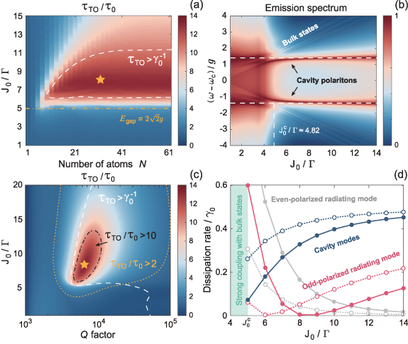
Figure 4. Optimal interaction strengths J0 and Q factor for lifetime enhancement of topological cavity polaritons. (a) Topology-enhanced lifetime of cavity polaritons  versus the number of atoms N and the interaction strength J0. Orange dashed dotted line indicates the critical J0 (i.e.
  ) for topological bandgap with a width of
  . Dashed white line surrounds the parameters range of subradiance, i.e.
  . Orange star denotes
  for dynamics shown in figure 3(b). (b) Emission spectrum of QE versus J0. The horizontal and vertical white dashed lines indicate the locations of cavity polaritons and
  , respectively. (c) Topology-enhanced lifetime of cavity polaritons
  versus the Q factor and the interaction strength J0. Black dashed dotted line and orange dotted line indicate
  and 2, respectively. (d) Dissipation from topological cavity polaritons to two cavity modes (blue lines) and the even- and odd-polarized radiating modes (light gray and red lines) for
  (solid lines with dots) and 0.2π (dashed lines with circles). Parameters not mentioned are the same as figure 3(b).
Download figure:
Standard image High-resolution imageFigure 4(c) shows that for a fixed J0, there exists an optimal Q factor for the maximal enhancement of lifetime  . With continually increased Q factor, the lifetime enhancement decreases. It is because a high-Q cavity leads to the weak interaction between the cavity QED system and the topological atom mirror. It also explains why the optimal J0 of maximal lifetime enhancement increases for high Q factor, since strong feedback from topological atoms is required in this case. Even so, a high-Q cavity is beneficial to produce the subradiant cavity polaritons (i.e. the lifetime
  ), as the white dashed line indicates, because τ0 is too small for a low-Q cavity. We evaluate that over tenfold lifetime enhancement of cavity polaritons can be achieved for a cavity with Q factor of 104 at 1550 nm and twofold lifetime enhancement is observed even for Q factor approaching 105.
To shed insights into the dissipative properties of topological cavity polaritons, we diagonalize the Lindblad operator (equation (2)) to obtain the dissipative matrix  , with χm
being the dissipation spectrum, which is shown in figure 9(a) (see appendix A.5 for more details). Four dissipative modes are found to have large dissipation rate, which are two polarized radiating modes corresponding to the even and odd sites in topological atom mirror and other two are related to cavity modes, as we see from the wave function shown in figure 9(b) of appendix A.5. In our model, the dissipation of odd-polarized radiating mode is greater than that of even-polarized radiating mode due to the odd number of atoms. The dissipation rate
, with χm
being the dissipation spectrum, which is shown in figure 9(a) (see appendix A.5 for more details). Four dissipative modes are found to have large dissipation rate, which are two polarized radiating modes corresponding to the even and odd sites in topological atom mirror and other two are related to cavity modes, as we see from the wave function shown in figure 9(b) of appendix A.5. In our model, the dissipation of odd-polarized radiating mode is greater than that of even-polarized radiating mode due to the odd number of atoms. The dissipation rate  from topological cavity polaritons to environment is given by the overlap between the polaritonic states and the radiating modes in the Lindblad operator, which is evaluated as [47]

where  is the eigenstate of
 ![$\operatorname{Re}\left[H_{\text {eff }}\right]$](https://content.cld.iop.org/journals/2058-9565/9/3/035019/revision2/qstad3f46ieqn139.gif) corresponding to the cavity polaritons. The results are plotted in figure 4(d), where it shows that the dissipation rate of odd-polarized radiating mode approaches to zero around
corresponding to the cavity polaritons. The results are plotted in figure 4(d), where it shows that the dissipation rate of odd-polarized radiating mode approaches to zero around  , while the dissipation rate contributed by the even-polarized radiating mode (cavity modes) is monotonically decreasing (increasing) with increased J0. We also find that the dissipation of radiating modes dramatically increases as J0 approaches to
  . In addition, a small φ that produces a large topological bandgap (see figure 3(f)) can reduce the dissipation rate of radiating modes. These results suggest that the system energy mainly dissipates from bulk states to environment in parameter range of
  . While for
  , the dissipation of cavity modes is dominated over the radiating modes and as a result, the minimum
  achieves around J0 corresponding to zero dissipation rate (
 ) of odd-polarized radiating mode.
2.3. Robustness against the disorder in topological atom mirror
In practice, the perturbations on system and imperfections of structure are inevitable. In this subsection, we investigate the impact of local disorder on the enhancement of lifetime for topological cavity polaritons. We introduce the random variation in atom position dj , interaction strength Jj , and frequency ωj in equations (10)–(13), then evaluate the lifetime of topological cavity polaritons in the same manner as figure 3(b).
In figure 5(a), we plot  with disordered positions for topological atoms, where the position of the jth atom is
  , with
  . It shows that the disorder in atom positions has small impact on the lifetime for
  , especially when
  . Though it affects the lifetime in a negative manner, we find that
  can still be obtained around
  . Different from the disorder in atom positions, the positive impact on lifetime is observed for disorder in interaction strengths with moderate disorder
  and
and  , as figure 5(b) shows. In this case, the interaction strength between the jth and (j + 1)th atoms is given by
  . The inset of figure 5(b) displays that
  at
at  manifests high robustness against the disorder in interaction strengths for various atom spacing. The results presented in figures 5(a) and (b) indicate that the disorder in atom positions has greater impact on the lifetime of topological cavity polaritons, as we can see that the lifetime variation of 2% disorder in atom positions is comparable and even slightly larger than that of 20% disorder in atom interactions around
  . It is because the impact of disorder in atom positions is nonlocal, which affects the coupling between the disordered atom and all the other atoms through the waveguide-mediated long-range hoppings. On the contrary, the disorder in atom interactions is local perturbation, which only alters the coupling between neighboring sites. Therefore, the lifetime enhancement manifests higher robustness against disorder in atom interactions. As for disorder in atom frequencies, its main effect is on the energies of edge and bulk states, thus the impact on the lifetime of topological cavity polaritons is not obvious if the topological bandgap is sufficiently large. Figure 5(c) shows the lifetime enhancement in presence of disorder in atom frequencies, where the strong disorder strength is considered. The frequency of the jth atom is randomly distributed in range of
 ![$\omega_j \in [\omega_c-g / \sqrt{2}, \omega_c+g / \sqrt{2}]$](https://content.cld.iop.org/journals/2058-9565/9/3/035019/revision2/qstad3f46ieqn168.gif) , where the maximal disorder strength is a half of the width of Rabi splitting. We can see that similar to figure 5(b), disorder in atom frequencies also begins to have noticeable effect around
, where the maximal disorder strength is a half of the width of Rabi splitting. We can see that similar to figure 5(b), disorder in atom frequencies also begins to have noticeable effect around  (vertical dashed dotted line), but in this case the lifetime of topological cavity polaritons is less sensitive to disorder when
  (vertical dashed line) as expected. Therefore, it implies that disorder in atom interactions and frequencies mainly affect the edge states and bulk states of topological atom mirror, respectively. We conclude from figure 5 that the presence of moderate disorder in atom mirror will not severely spoil the enhanced lifetime of topological cavity polaritons.
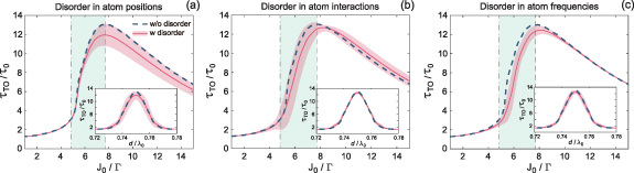
Figure 5. Topologically robust enhancement of lifetime  versus interaction strength J0 with disorder in atom positions (a), atom interactions (b), and atom frequencies (c). The disorder ranges are
 ![$\Delta d_j \in [-0.02 d, 0.02 d]$](https://content.cld.iop.org/journals/2058-9565/9/3/035019/revision2/qstad3f46ieqn147.gif) for atom positions,
for atom positions, ![$\Delta J_j \in [-0.2 J_0, 0.2 J_0]$](https://content.cld.iop.org/journals/2058-9565/9/3/035019/revision2/qstad3f46ieqn148.gif) for atom interactions, and
for atom interactions, and ![$\Delta\omega_j \in [-g / \sqrt{2}, g / \sqrt{2}]$](https://content.cld.iop.org/journals/2058-9565/9/3/035019/revision2/qstad3f46ieqn149.gif) for atom frequencies. The pink solid line represents the mean value averaged over 100 random realizations of disordered topological atom mirror, with pink shaded area indicating the standard deviation. The green shaded region indicates the parameter range of
for atom frequencies. The pink solid line represents the mean value averaged over 100 random realizations of disordered topological atom mirror, with pink shaded area indicating the standard deviation. The green shaded region indicates the parameter range of  , where the vertical dashed dotted line and dashed line label
  and
and  , respectively. The insets show
  at
at  versus atom spacing d. Other parameters are the same as figure 3(b).
Download figure:
Standard image High-resolution image2.4. Physical implementation
The proposed model can be implemented in various quantum systems. Particularly, it should be emphasized that the parameters used in this work are attainable in nanophotonic platform with semiconductor QEs. Taking InGaAs quantum dots for an example, the intrinsic decay is  at cryogenic temperatures [80]. For the strong-coupling regime under investigation,
  corresponds to a cavity with Q factor of
  . The QE-cavity coupling strength
  can be obtained, for instance, in a WGM microdisk with 3µm radius [21, 34].
The dimerized interactions between the atoms in mirror can be achieved by additional structures or advanced technologies according to the kinds of quantum system. For quantum dot arrays, the switchable coherent coupling between two neighboring sites is usually provided by the tunnel barrier of electrostatic potential, which can be tuned through control gate [44, 74, 81]. In this respect, very recently the experimental realization of SSH chain based on ten semiconductor QEs with tunable interaction strengths has been reported [44]. With state-of-art technology, the precision of positioning a QE can reach  nm [82], which is less than 2% compared to the emission wavelength of QE. As the results of figure 5(a) indicates, such experimental uncertainties has limited impact on the lifetime of topological cavity polaritons. In addition, for the case of single-photon excitation as we study in this work, the topological atom mirror can be replaced by cavity counterpart [55], which is a more feasible experimental configuration to tune the system parameters. Besides the solid-state QEs, the technology of optical tweezers has already been applied to construct one- and two-dimensional atom arrays with the number of cold atoms up to 200 [83–85]. Alternatively, the cavity-magnon systems [13] and superconducting circuits [31, 43] are also promising candidates to implement topological atom mirror for the advance in realizing multi-atom interactions over extended distances. For instance, in superconducting qubit architecture the tunable coherent coupling between two qubits has been achieved with a Josephson junction and followed by a linear inductor to ground [86]. While in circuit quantum electrodynamics, the individual sites are formed with resonators while the tunnel couplings are implemented with coupling capacitors [74]. Therefore, the considerable enhancement of lifetime by over an order of magnitude predicted here is achievable for cavity polaritons in diverse quantum systems.
3. Conclusion and outlook
In summary, we propose a scheme for narrowing the linewidth of cavity polaritons combined with robustness by coupling a one-dimensional topological atom mirror to the cavity QED system based on WGM resonator. The cavity polaritons become subradiant, with a linewidth smaller than that of a single QE through the coupling of cavity mode to edge states in dissipationless topological phase. Accordingly, the lifetime can be improved by over an order of magnitude. The subradiance of cavity polaritons is protected by the topological bandgap and hence can survive in the disordered atom mirror.
Our architecture exhibits prominent advantages in at least three aspects. Firstly, the maximal enhancement of lifetime is achieved in a cavity with moderate Q factor of  , which gets rid of the drawback of poor excitation and collection efficiencies in conventional approach that reduces the linewidth by the use of a high-Q cavity. This feature combined with the openness of semi-infinite waveguide benefits the practical applications. Importantly, several unit cells, typically
  atoms, are sufficient to narrow the linewidth of cavity polaritons to a value comparable to a single QE in the free space. Topological atom mirror of this scale has been demonstrated with state-of-art technology of nanofabrication. Last but not least, the property of topological protection empowers the subradiant cavity polaritons to have high tolerance for fabrication imperfections and experimental uncertainties. Moving forward, future endeavors can devote to explore the effects of coherent time-delayed feedback on lifetime enhancement [87], or conceive the scheme of in situ and dynamical topological manipulation of quantum states [74]. Therefore, our scheme offers a promising platform for exploring topological quantum optics and may be potentially used for long-time storage of quantum states in experiments, which is crucial to push quantum technologies toward practical applications.
Acknowledgments
Y W Lu acknowledges the support of National Natural Science Foundation of China (Grant Nos. 62205061 and 12274192). Z Liao acknowledges the support of National Key R&D Program of China (Grant No. 2021YFA1400800), the Guangdong Basic and Applied Basic Research Foundation (Grant No. 2023B1515040023) and the Natural Science Foundations of Guangdong (Grant No. 2021A1515010039).
Data availability statement
All data that support the findings of this study are included within the article.
Conflict of interest
The authors declare no competing interests.
Appendix:
A.1. Derivation of the extended cascaded quantum master equation
We derive the extended cascaded quantum master equation (equations (1) and (2)) by tracing out the degrees of freedom of the waveguide [65, 88]. The system Hamiltonian including the waveguide modes is given by ( )
)

with  given in equations (3)–(6). Hw
is the free Hamiltonian of waveguide
given in equations (3)–(6). Hw
is the free Hamiltonian of waveguide
where bL
(bR
) is the bosonic annihilation operator of the left-propagating (right-propagating) waveguide mode with frequency ω. The limits of integration are ![$(-\infty, 0]$](https://content.cld.iop.org/journals/2058-9565/9/3/035019/revision2/qstad3f46ieqn180.gif) and
and  for bL
and bR
, respectively, i.e.
for bL
and bR
, respectively, i.e.  . But the limits of integration are omitted in the following derivation for the sake of simplicity. Hsw
is the interaction Hamiltonian that describes the cavity-waveguide and atom-waveguide interactions
. But the limits of integration are omitted in the following derivation for the sake of simplicity. Hsw
is the interaction Hamiltonian that describes the cavity-waveguide and atom-waveguide interactions
where the wave vector  , with
  (
( ) being the corresponding group velocity [65]. For the sake of convenience, we have used the notions cR
=
) being the corresponding group velocity [65]. For the sake of convenience, we have used the notions cR
=  and
and  since the CCW and CW modes are coupled to the right- and left-propagating guided modes, respectively. x0 is the location of cavity-waveguide junction and xj
indicates the location of jth atom that couples to the waveguide. Applying the transformation
since the CCW and CW modes are coupled to the right- and left-propagating guided modes, respectively. x0 is the location of cavity-waveguide junction and xj
indicates the location of jth atom that couples to the waveguide. Applying the transformation  with
with ![$U = \exp \left[i\left(\omega_c \sum_{\lambda = R, L} c_\lambda^{\dagger} c_\lambda+\sum_{j = 1}^N \omega_j \sigma_{+}^{(j)} \sigma_{-}^{(j)}+\sum_{\lambda = R, L} \int \textrm{d} \omega \omega b_\lambda^{\dagger} b_\lambda\right)t\right]$](https://content.cld.iop.org/journals/2058-9565/9/3/035019/revision2/qstad3f46ieqn189.gif) , we have
, we have

where  and
and  . The equation of bλ
can be obtained from the Heisenberg equation
. The equation of bλ
can be obtained from the Heisenberg equation

Formally integrating the above equation, we have

where the initial condition  is imposed since the waveguide is initially in the vacuum state. On the other hand, the equation of motion of arbitrary operator O reads
Substituting  into the above equation, we obtain
where  and
and  . We perform the Born–Markov approximation
  by assuming the time delay
  between the atoms and
  between the cavity modes and the atoms are sufficiently small and can be neglected. Therefore, we have

Similarly,


where  is the step function, which accounts for the time order of the propagating direction of guided modes. For example, equation (A10) corresponds to left-propagating guided mode while equation (A11) only survives in right-propagating guided mode. Substituting equations (A9)–(A12) into equation (A8) and taking the averages, we obtain
Since ![$\langle O(t)\rangle = \mathrm{Tr}\left[O(t)\rho(0)\right] = \mathrm{Tr}\left[O\rho(t)\right]$](https://content.cld.iop.org/journals/2058-9565/9/3/035019/revision2/qstad3f46ieqn200.gif) , we can simplify the average of operators in the above equation by using the cyclic property of trace. For example, the terms in the third line of equation (A13) can be written as
, we can simplify the average of operators in the above equation by using the cyclic property of trace. For example, the terms in the third line of equation (A13) can be written as


where the operators without time means to take the initial value, i.e.  . Applying the cyclic property of trace to other terms of equation (A13), we obtain the following equation
According to the relation ![$\langle O(t)\rangle = \mathrm{Tr}\left[O\rho(t)\right]$](https://content.cld.iop.org/journals/2058-9565/9/3/035019/revision2/qstad3f46ieqn202.gif) , we arrive at the extended cascaded quantum master equation
, we arrive at the extended cascaded quantum master equation
Note that we define x0 = 0 in the main text, thus  in the last two lines on the right-hand side. In addition, the second and third terms on the right-hand side can be expressed using the Liouvillian superoperator. Taking into account the free-space decay γ0 of atoms, we arrive at the extended cascaded quantum master equation given in equations (1) and (2) in the main text.
To further verify the correctness of Lindblad operators derived in equation (A17), in figure 6 we compare the quantum dynamics obtained by numerically calculating the extended quantum master equation (equations (1) and (2)) using QuTip [89] with that given by equations (10)–(13), where good agreement can be seen.

Figure 6. (a) and (b) Quantum dynamics of cavity QED system and the atoms in mirror, respectively. The dots represent the corresponding results obtained using QuTip [89]. The model and parameters of system are the same as figure 3(b) in the main text, except for the number of topological atoms is N = 3. The code files are available at [90] for reproducing the results.
Download figure:
Standard image High-resolution imageA.2. Inclusion of planewave excitation in the extended cascaded quantum master equation and the input–output boundary condition
The extended cascaded quantum master equation in equations (1)–(6) in the main text does not account for the excitation of the system. In this subsection, we consider a concrete excitation configuration, i.e. planewave excitation through the right-propagating guided mode of waveguide (bR ), and derive the corresponding quantum master equation. To include the excitation, we start by formally integrating equation (A5) and obtain

where  and
and  due to the existence of incident waveguide photons. Substituting the above equation into equation (A7), we find the additional terms compared to equation (A8)

and

which yields the following Lindblad operator for excitation

where  and
and  is the driving for CCW mode and atoms, respectively, with
  and
and  accounting for the absorption of the incident waveguide photons. In this work, we consider the single-photon planewave excitation, the multiphoton excitation can be referred to, e.g. [91–93]. We can see that for a monochromatic planewave, pc
and pe
reduce to a complex number. In this case, we have
accounting for the absorption of the incident waveguide photons. In this work, we consider the single-photon planewave excitation, the multiphoton excitation can be referred to, e.g. [91–93]. We can see that for a monochromatic planewave, pc
and pe
reduce to a complex number. In this case, we have

Accordingly, the extended cascaded quantum master equation is given by

which yields equations (14)–(16) in the main text.
To derive the input–output relations, we integrate equation (A5) from t to tf
(i.e.  ) and obtain

By comparing with equation (A18), we have

We use the following definition of input–output operators [1, 78]


where a phase factor corresponding to the light propagating from the waveguide-cavity junction to the rightmost atom appears in equation (A26). It means that the right output field propagates freely after scattered by the rightmost atom. Using equations (A26) and (A27), we can obtain the input–output relation from equation (A25)
Since  , we can extend the lower limit of integration to
Using the identity  , we obtain
Applying the Born–Markovian approximation, the above equation becomes

With a fashion similar to equations (A25)–(A32), we can obtain the input–output relation for left-propagating guided mode

with

and

where a phase factor is added in  since the left output field propagates freely after scattered by the waveguide-cavity junction. Since
  for left-incident planewave, the input–output relations equations (A32) and (A33) yield equations (18)–(21) in the main text. Note that
  (equation (A35)) is different from the field amplitude ain in equation (16).
A.3. Dissipative and dissipationless edge states of bare topological atom mirror
To demonstrate the dissipationless feature of edge states, the spontaneous emission rate of atoms is omitted, i.e. γ0 = 0. In figure 7(a), we plot the decay rates ![$\Gamma_\mathrm{edge} = -2\operatorname{Im}\left[E_\mathrm{edge} \right]$](https://content.cld.iop.org/journals/2058-9565/9/3/035019/revision2/qstad3f46ieqn222.gif) of edge states with atom spacings
of edge states with atom spacings  and
and  versus intensity strength J0. It shows that
  of edge states with
  suddenly drops to zero at a critical
  regardless of φ, demonstrating the dissipationless feature; while the edge states in dissipative topological phase (
 ) manifests the distinct feature of slowly decreased
  without transition as J0 increases. Different from the original SSH model, in our setup the interplay between the dimerized interaction and the waveguide-mediated long-range interaction gives rise to topological phase transition. Without considering the dissipation interaction, the zero-energy states are found at atomic spacing
  and
and  , and the corresponding winding number is W = 1 for
  and
and  , respectively [47]. However, as we see from figure 7(a), the edge state at
  is not protected from the dissipation, while at
  the edge state becomes dissipationless for
  . Appendix A.5 is devoted to study the dissipation spectrum, where we show that how the Lindblad operator protects the dissipationless edge state.
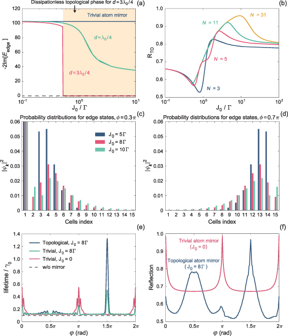
Figure 7. (a) Decay rates of edge states with two atom spacings,  and
and  . The latter becomes dissipationless when
  . The horizontal dashed black line indicates the zero decay rate. (b) Reflectivity
  versus intensity strength J0 for bare topological atom mirror with different number of atoms N. (c) and (d) Probability distributions of edge states for topological atom mirror with
  and 0.7π, respectively. (e) and (f) Lifetime of topological and trivial cavity polaritons versus ϕ and the corresponding reflectivity. Parameters not mentioned are the same as figure 2 in the main text. γ0 = 0 in (a).
Download figure:
Standard image High-resolution imageIn figures 7(c) and (d), we investigate the probability distributions of edge states for a bare topological atom mirror, i.e. without coupling to the cavity QED system. We can see that the delocalization populates all unit cells for a sufficient large interaction strength ( ), thus
  for dissipationless edge states. Furthermore, the topological edge states localize at the left (right) boundary when
  (
( ). The long-range hoppings between topological atoms induced by waveguide destroys the exponential localization of edge states: the probability decreases non-monotonically from the boundary and extends to the opposite boundary, exhibiting strong delocalization with a large intensity strength J0. The delocalization means the increased dissipation of atom mirror and therefore, we can see in figure 7(b) that it requires more atoms to achieve high reflectivity for a large J0. But on the other hand, a large J0 can produce a wide topological bandgap, which is beneficial to suppress the dissipation from edge states to bulk states and achieve high reflectivity. The balance between the delocalization and the dissipation induced by bulk states yields an optimal J0 for the maximal reflectivity of topological atom mirror with a fixed number of atoms.
We stress that for γ0 = 0, both topological and trivial atom mirrors have unity reflectivity, while the cavity polaritons of latter are dissipative. Therefore, the formation of bound cavity polaritons cannot understood as a result of classical destructive interference between the cavity field and the reflected field through atom mirror. The evidence supporting our claim is that the lifetime of topological cavity polaritons is prominently greater than the non-topological cavity polaritons, as we see in figure 7(e), while the maximal reflectivity of topological atom mirror is slightly smaller than the trivial atom mirror with Bragg reflection condition (i.e.  ), as figure 7(f) shows. It is because there is a superradiant state with decay rate
  in trivial atom mirror, which has zero energy at
  , see the eigenenergies shown in the inset of figure 1, and hence resonantly couples to the QE and cavity. As a result, the bound cavity polaritons cannot form with a trivial atom mirror. In contrast, the zero-energy edge state at
  has zero decay when γ0 = 0. Combined with a large bandgap that separates the cavity polaritons from bulk states, the topological cavity polaritons can be bound.
In order to clarify the effects of direct interaction on lifetime enhancement of cavity polaritons, we include the direct interaction between atoms in trivial mirror with the same interaction strength J0 as that of topological atom mirror, but the interaction is not staggered, i.e. equal to the case of  in topological atom mirror. The resultant lifetime of cavity polaritons are shown as the green line in figure 7(e), where we can see that the introduction of such coherent coupling cannot achieve significant enhancement of lifetime for trivial atom mirror. The results shown in figures 7(e) and (f) indicate the significance of topological atom mirror in enhancing the lifetime of cavity polaritons.
A.4. Emission spectrum of QE and probability distributions of hybrid edge modes
Figure 8(a) presents the logarithmic plot of the emission spectrum of QE versus φ. By comparing with the reflection spectrum shown in figure 3(f), we can see that they demonstrate similar pattern and features, such as the variation of topological bandgap and the distinct linewidth of cavity polaritons for the left and right edge states. However, for observing the linewidth narrowing of polaritonic states (Rabi peaks), the emission spectrum of QE is preferred since the signal of bulk states is weak. In addition, we find that the composed system shows a feature of SSH model with even sites, where two hybrid edge modes with a finite gap can be seen in the region of  , which is hard to recognize in the reflection spectrum. The probability distributions shown in figure 8(b) indicate the formation of hybrid edge modes with even and odd parities, distinguishing from the left or right edge states of bare topological atom mirror that populate either the odd or even sites.

Figure 8. (a) Emission spectrum of QE for cavity QED system with topological atom mirror versus φ under the strong-coupling regime. (b) Probability distributions of hybrid edge modes versus atoms index for  indicated by the dashed line in (a). Parameters are the same as figure 3(f). (c) A closeup of the emission spectrum of QE for the strong-coupling anticrossing between bulk states and polaritonic states, which are indicated by the black dashed line and the light gray lines, respectively. Parameters are the same as figure 4(b). (d) Emission spectrum of QE and the reflection and transmission spectra for dark cavity polaritons in the planewave excitation, with φ indicated by the dashed dotted line in (a).
Download figure:
Standard image High-resolution imageOn the other hand, we find an inconspicuous anticrossing at  in figure 8(a), indicating the strong coupling between bulk states and polaritonic states. This anticrossing behaviour is more evident in the emission spectrum of QE versus J0, as figure 8(c) shows. In stark contrast to the conventional strong-coupling anticrossing that is observed by tuning the frequency detuning, here J0 plays the role of frequency detuning in the strong-coupling anticrossing. It is because the variation of J0 does not alter the energy of polaritonic states, but the width of topological bandgap linearly enlarges with increased J0. Therefore, J0 can change the energies of bulk states.
It is important to note that in the reflection spectrum of figure 3(e), two dips corresponding to cavity polaritons are nonvanishing around  , while this phenomenon is not found in the emission spectrum of QE, as figure 8(d) shows, where the black arrows indicate the polaritonic states. The results reveal that the formation of dark cavity polaritons is related to specific excitation method. For the configuration of planewave excitation, these dark cavity polaritons stem from destructive interference between the incident and scattering photons.
A.5. Dissipation spectrum and radiating modes
The dissipative interaction is described by the Lindblad operator ![$\mathcal{D}[\rho]$](https://content.cld.iop.org/journals/2058-9565/9/3/035019/revision2/qstad3f46ieqn250.gif) (equation (2)), which can be recast in terms of jump operators vm
, the (N + 3) eigenvectors of
(equation (2)), which can be recast in terms of jump operators vm
, the (N + 3) eigenvectors of ![$\mathcal{D}[\rho]$](https://content.cld.iop.org/journals/2058-9565/9/3/035019/revision2/qstad3f46ieqn251.gif) . The decay rates χm
are found as the corresponding eigenvalues.
. The decay rates χm
are found as the corresponding eigenvalues. ![$\mathcal{D}[\rho]$](https://content.cld.iop.org/journals/2058-9565/9/3/035019/revision2/qstad3f46ieqn252.gif) can be rewritten as [47, 94]
can be rewritten as [47, 94]

The diagonalization of ![$\mathcal{D}[\rho]$](https://content.cld.iop.org/journals/2058-9565/9/3/035019/revision2/qstad3f46ieqn253.gif) yields a dissipation matrix γ, which can be expressed as follows
yields a dissipation matrix γ, which can be expressed as follows

where χm
is also called the dissipation spectrum. Figure 9(a) shows χm
for the composed system in the strong-coupling regime with 31 atoms in mirror. We can see that the dissipation of modes m = 1 and 34 is  , thus they are related to two cavity modes. Two radiating modes indexed by m = 2 and 3 can be found in the dissipation spectrum, whose dissipation is much greater than other modes. Figure 9(b) plots the wave function of two radiating modes versus atoms index, where we can identify the odd and even polarization for m = 2 and 3, respectively. With the eigenstates
  of Hamiltonian
 ![$\operatorname{Re}\left[H_\mathrm{eff} \right]$](https://content.cld.iop.org/journals/2058-9565/9/3/035019/revision2/qstad3f46ieqn256.gif) , we can evaluate the dissipation rate
, we can evaluate the dissipation rate  of the nth eigenstate to the environment

with  being the contribution of the mth mode in dissipation spectrum

Particularly, the eigenstates corresponding to cavity polaritons is indicated by  . Figure 4(d) shows the contributions of cavity modes (
 and
and  ) and radiating modes (
 and
and  ) to the dissipation of cavity polaritons.

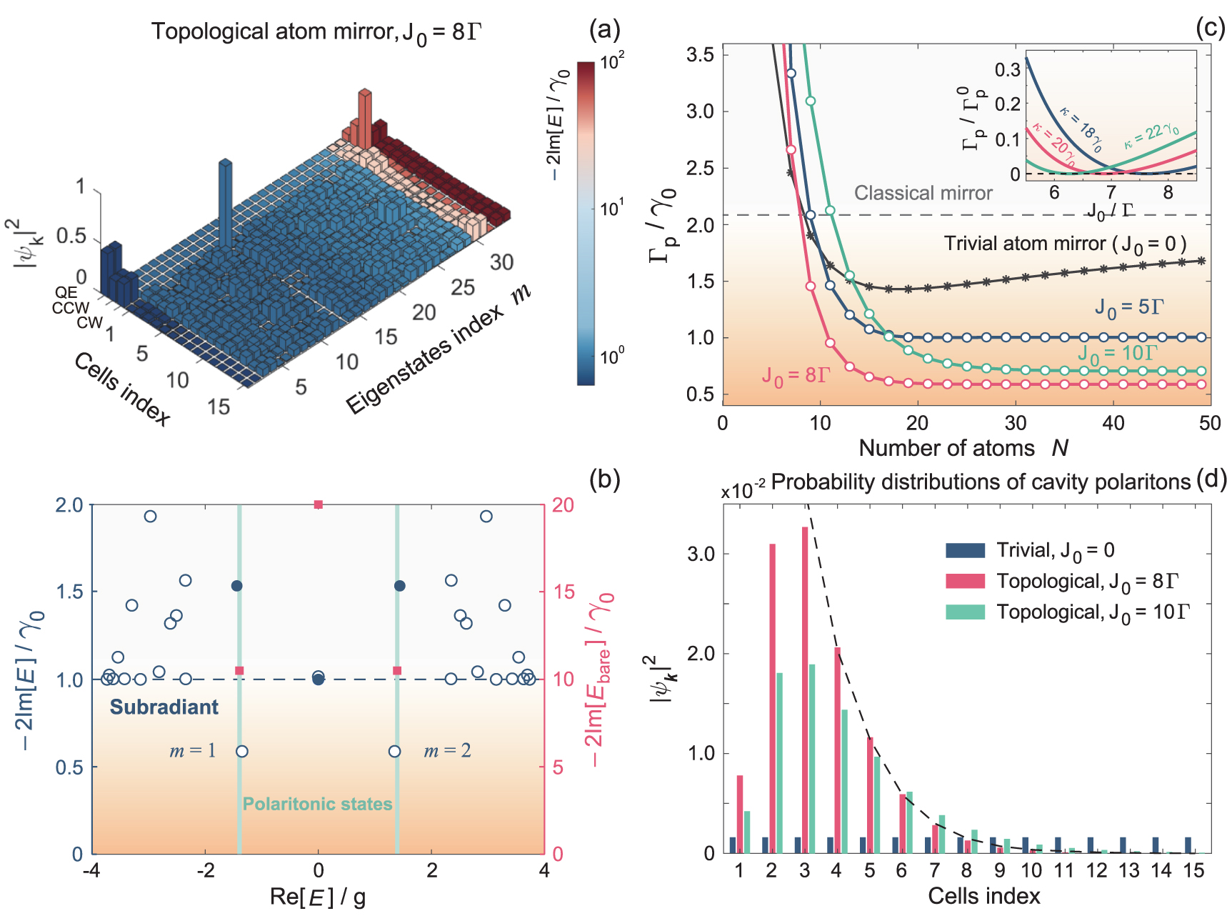
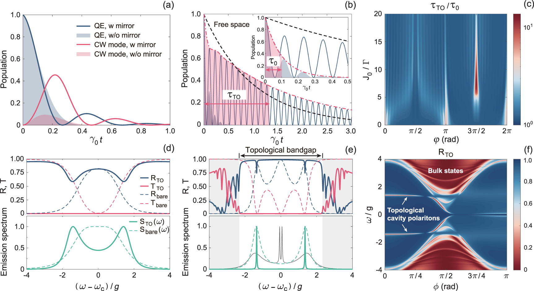
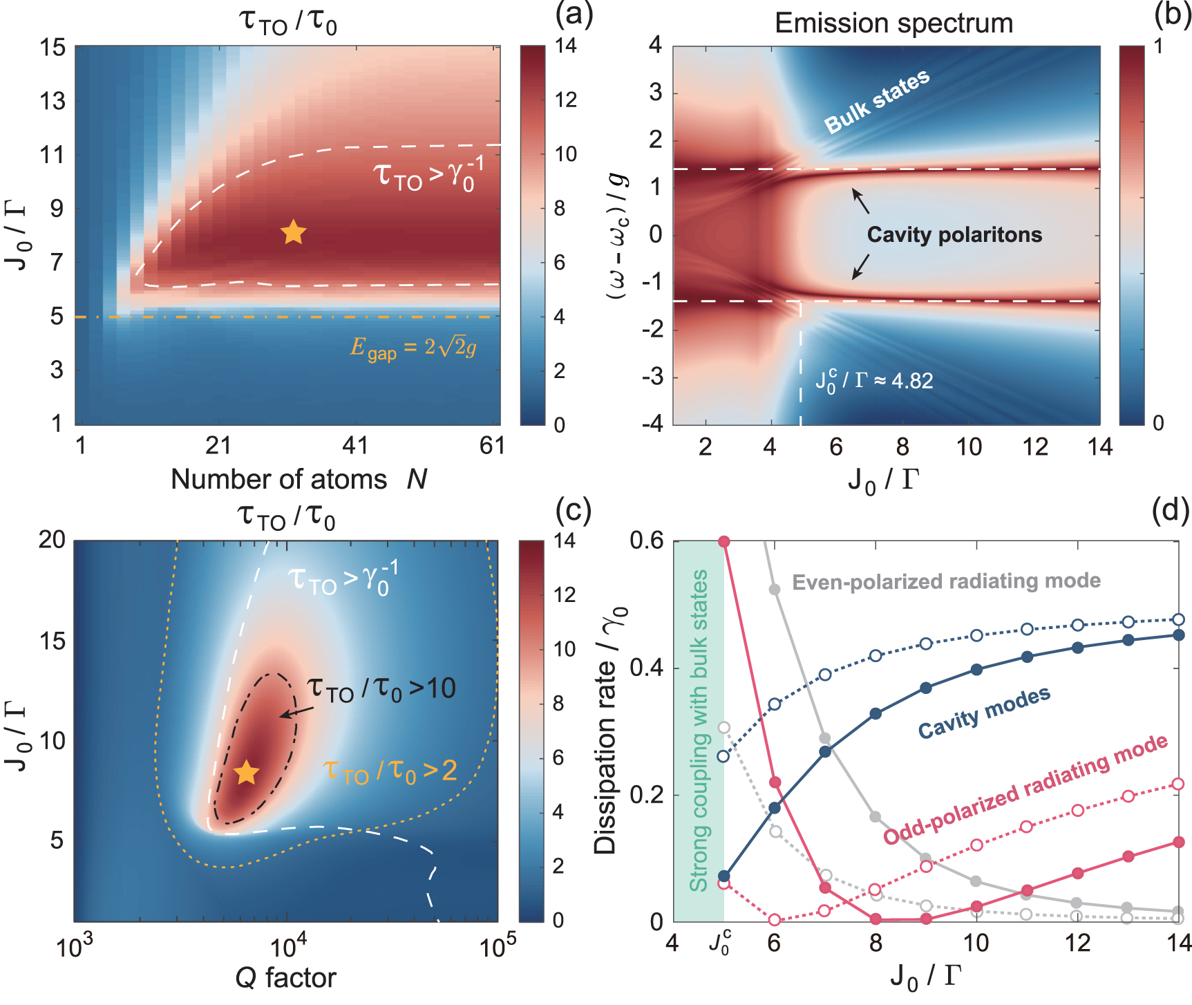
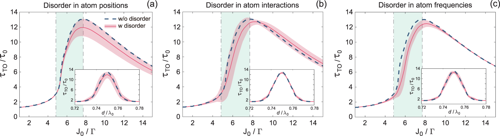
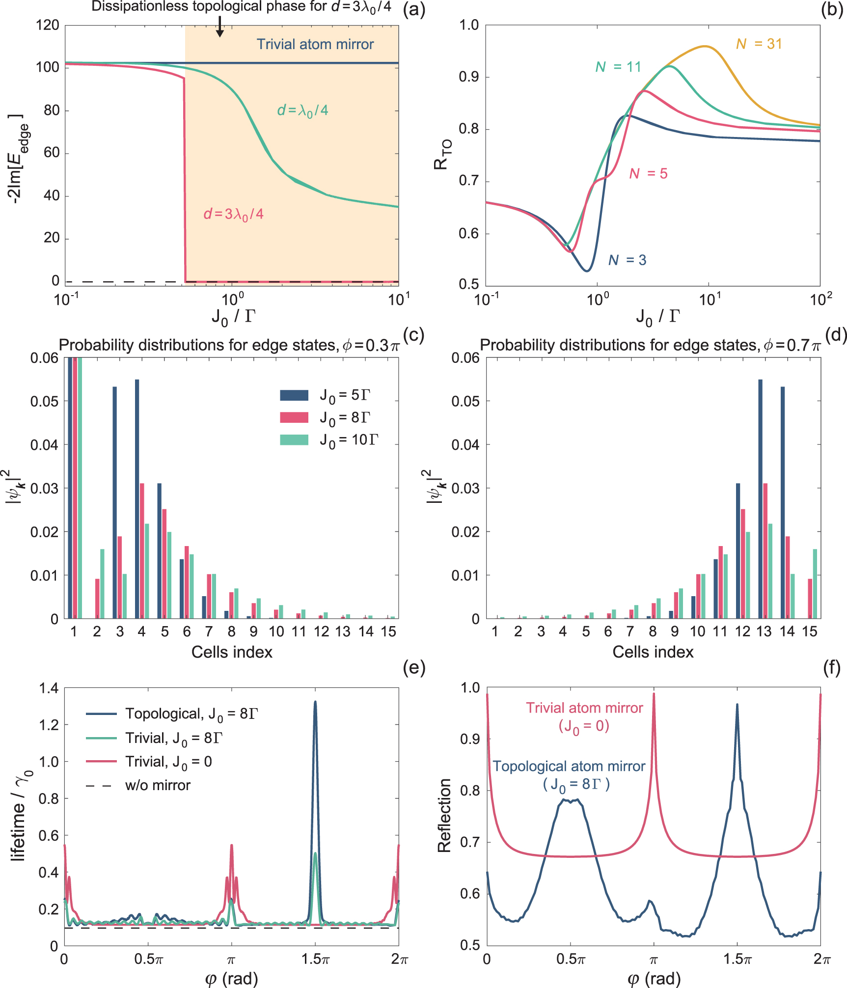
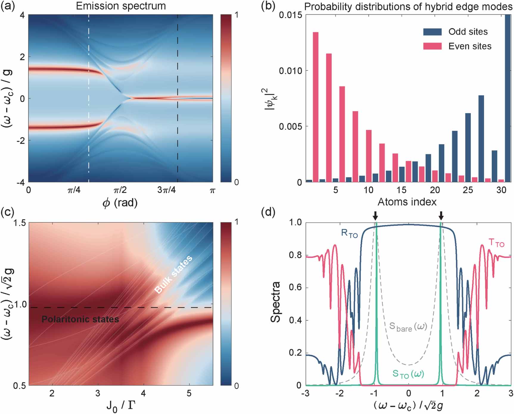
Figure 9. Dissipation spectrum (a) and the wave function of two radiating modes (b) of topological atom mirror. The parameters are the same as figure 4(d).
Download figure:
Standard image High-resolution image