Article

13.2 kV Class 3-Phase Solid State Transformer System Based on EtherCAT Communication

Electric Propulsion Research Center, Industry Applications Research Division, KERI, Changwon 51543, Korea
*
Author to whom correspondence should be addressed.
Electronics 2022, 11(19), 3092; https://doi.org/10.3390/electronics11193092
Submission received: 29 August 2022 / Revised: 21 September 2022 / Accepted: 25 September 2022 / Published: 27 September 2022

Abstract

:
This paper presents a 13.2 kV class 3-phase solid-state transformer (SST) based on EtherCAT communication. In general, when the structure of the unit module is determined, the number of high-frequency isolated transformers (HFIT) is also proportional to the number of modules. The structure most considered in SST is a 1:1 combination of AC/DC converter and DC/DC converter. To optimally implement a 3-phase SST, a topology for reducing passive elements such as switching elements and HFIT is proposed. It also describes the design of HFIT used in DC/DC converter. EtherCAT communication with high transmission speed and expandability is applied to control the SST composed of unit modules stably, and a multi-core microcontroller unit (MCU) is applied to achieve both a high-speed communication cycle and complicated control algorithm execution. The discussions are validated using a 300 kW 13.2 kV class 3-phase SST prototype in various conditions.

1. Introduction

Converting high-voltage MVAC to DC generally consists of three steps: a passive transformer that converts high-voltage AC to low-voltage AC, an AC/DC converter, and a DC/DC converter. Since a solid state transformer (SST) consists of two stages of an AC/DC converter and a DC/DC converter, the volume and weight can be reduced compared to the system, including the existing low-frequency transformer. In addition, since high-quality power can be supplied by controlling voltage drop, reactive power compensation, and harmonic reduction, various studies on SST are being conducted to replace the existing passive transformer with the next-generation intelligent transformer in various electrical applications [1,2,3,4,5,6,7,8,9,10,11,12]. However, despite a lot of research on SST in the past, there has been no development of a 3-phase SST that can be commercialized by connecting to MVAC high voltage.
The basic research on the development of SST using non-commercial S i C devices of 10 kV or higher were mainly conducted at universities [13,14,15]. At present, S i C devices of 3000 V or higher are being developed by major device makers, but they are very expensive and difficult to apply to actual systems. Considering the cost-effectiveness, commercial S i C devices that can be actually selected for manufacturing SST are as narrow as 1200∼1700 V devices. Therefore, it is necessary to study the structure of an SST having an efficient multi-level structure in which modules are stacked in series and parallel using devices with low withstand voltage. Although there are various topologies for SST, the most commonly considered structure is the one in which an AC/DC converter and dual active bridge (DAB) converter are combined in a 1:1 ratio. In this case, when the unit module structure is determined, the number of high-frequency isolated transformers (HFIT) is also proportional to the number of modules. Therefore, to optimally implement a 3-phase SST system, a topology optimization study is required to reduce switching elements and passive elements.
In the configuration of a 3-phase SST system applied to MVDC-class high voltage and large-capacity systems, many unit modules are inevitably configured in series and parallel [16,17,18,19]. As the number of modules increases, the amount of data required for control and real-time observation for protection increases. In the multi-level converter, the shorter the control period, the better the voltage and current control performance [20,21]. To improve control performance and reliability, a controller for a 3-phase SST system should be developed as a communication method that has high speed and can stably process a lot of data at the same time.
A controller area network (CAN) and serial communication interface (SCI) communication have the advantage that they can be easily implemented in the controller of the DSP-based power conversion system. However, this method is not suitable for real-time processing of data of many modules due to its slow speed. In the past, there have been cases of developing SST systems using CAN and SCI communication methods, but to overcome the limitations of communication speed and data throughput, a controller with a complex structure that uses multiple communications is configured [22,23]. EtherCAT communication is widely used in industrial applications due to its high-speed transmission and accurate synchronization performance. EtherCAT communication is full-duplex communication with a high-speed transmission of 100 Mbps. In addition, EtherCAT has the advantage of being able to flexibly configure network topologies such as line, tree, and star. Therefore, EtherCAT communication is suitable for SST requiring high transmission speed and expandability.
In this paper, a 3-phase SST system based on a quadruple active bridge (QAB) converter is proposed to optimize the unit module. If the QAB converter is applied to an SST system, the number of switches in the secondary-side rectification stage and the number of HFITs can be reduced, and the number and size of elements of a unit module can be optimized. In addition, to control the 3-phase SST system with high performance and reliability, the EtherCAT communication-based control system is capable of 50 µs high-speed communication is proposed. A multi-core microcontroller unit (MCU) was applied to the controller for the SST system to ensure that the control algorithm was implemented time-stably with a high-speed communication cycle of 50 µs. The performance was verified by manufacturing a prototype of a 13.2 kV class 3-phase SST system.

2. Structure of the Proposed 3-Phase Solid State Transformer

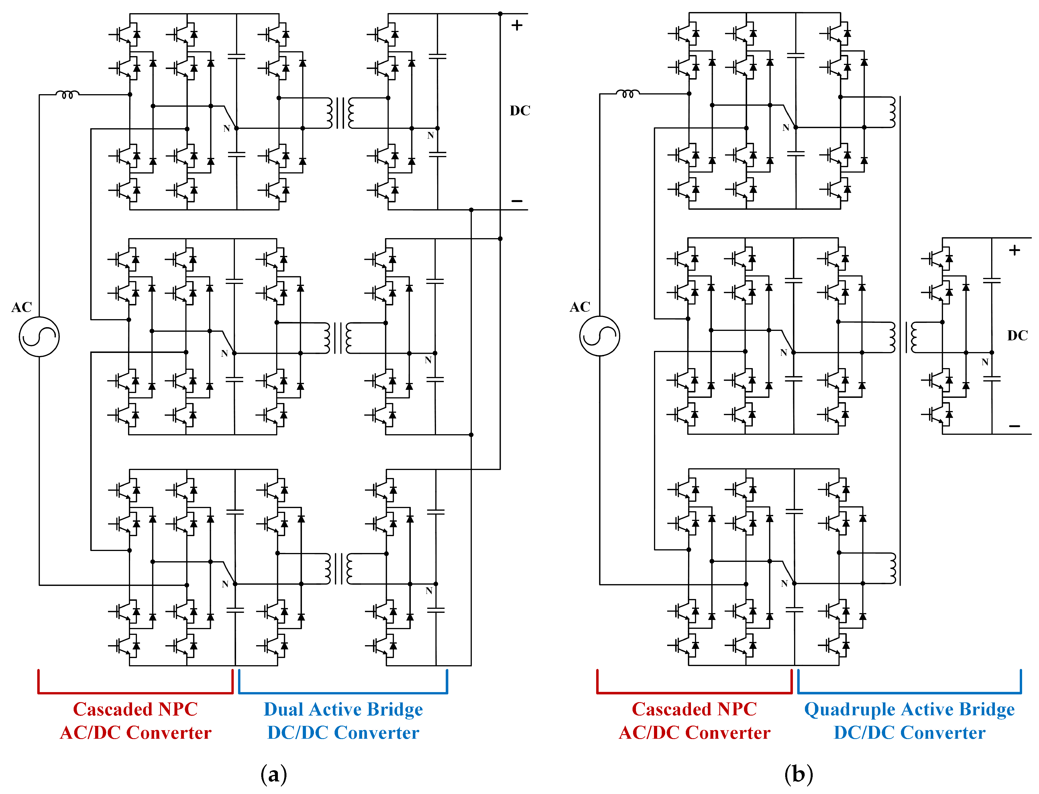
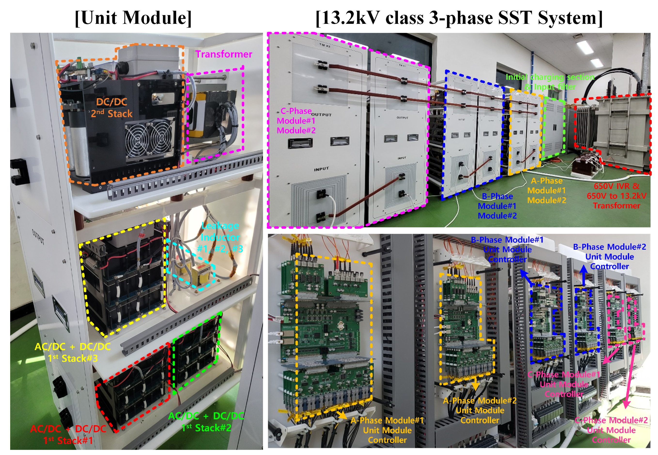
2.1. A Proposed Unit Module Based on QAB Converter

The HFIT of each unit module used in an SST system must each have isolation characteristics that cover more than the margin of the MVAC input voltage level. Since each unit module has a structure including an HFIT and the volume occupied by the HFIT is high, it is important to minimize the use of the HFIT for miniaturization of the SST system. As shown in Figure 1a, in the case of a structure in which an AC/DC converter and a DAB converter are combined in a 1:1 ratio, it is a disadvantage that as many HFITs as the number of unit modules must be used.
Figure 1b shows the circuit structure of the unit module of the SST proposed in this paper. The AC / DC converter constituting the proposed unit module is composed of a 13-level neutral-point clamped (NPC) full-bridge converter, and the DC / DC converter is composed of a QAB converter structure. Unlike the general method, the proposed QAB converter has a structure in which the output of the AC/DC converter of the 3-cascade structure is connected to the input terminal. The proposed method has the advantage of reducing the system volume while significantly reducing the number of HFITs used compared to the existing method because the circuit can be configured with one HFIT in the AC/DC converter of the three cascade structure.
Table 1 shows the number of elements constituting the unit module of the conventional structure and proposed structure. The proposed circuit can reduce the use of switching devices, clamp diodes, output capacitors, and sensors of the secondary-side rectification stage compared to the conventional method, thereby reducing costs and having the advantage of improving the stability of the system. In addition, since the peripheral components of the control board for controlling the unit module are also greatly reduced, the effect of cost reduction is higher. In terms of the configuration of the control algorithm, the proposed structure of the SST system reduces the output parallel control compared to the conventional SST system. It can reduce the size of communication data for parallel control and has various advantages such as algorithm computation time.

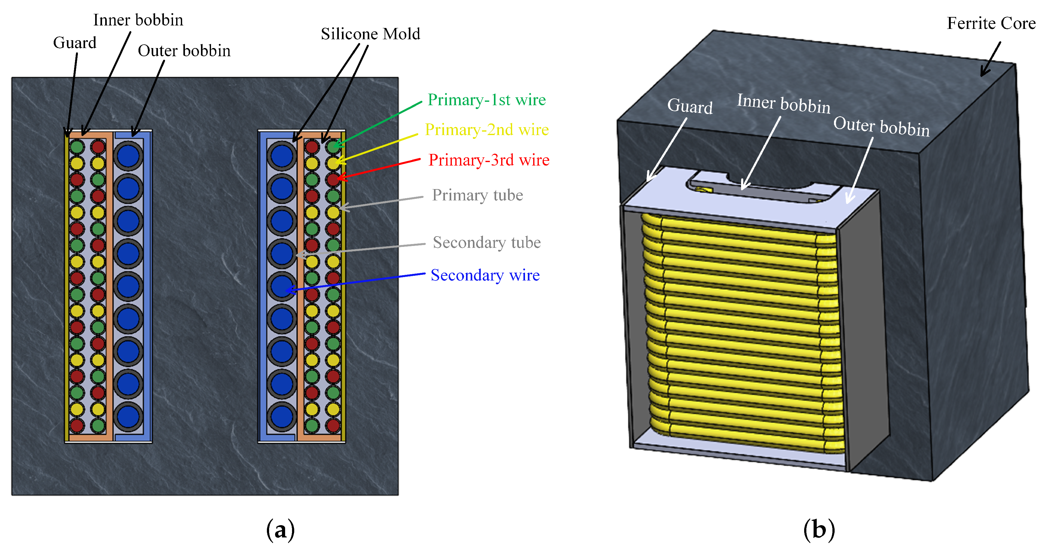
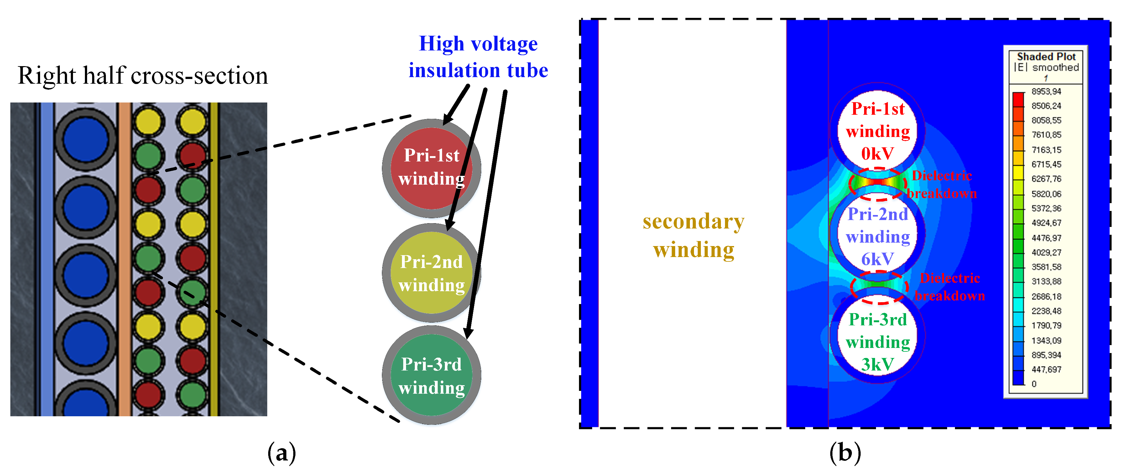
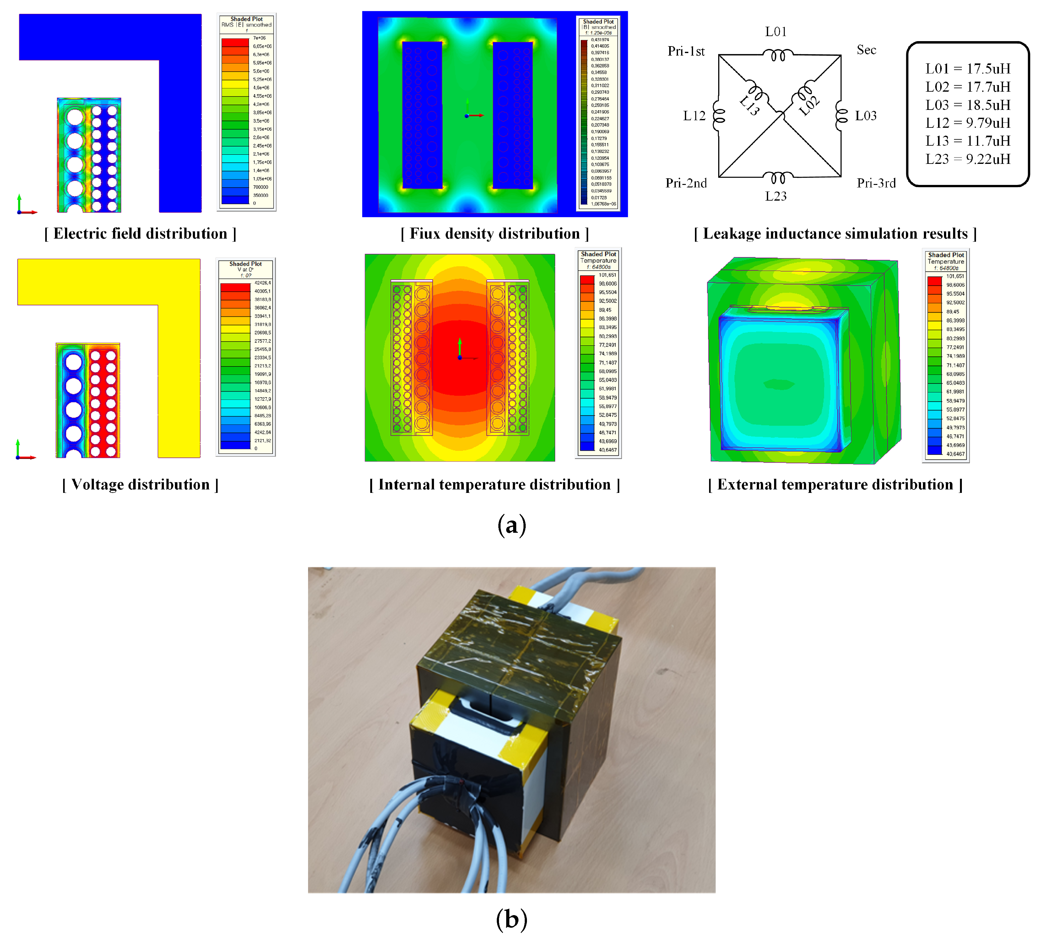
2.2. High-Voltage Isolated High-Frequency Transformer

An HFIT in a DC/DC converter can be applied with a potential difference equivalent to that of an SST system. According to I E C 60076 , a 13.2 k V r m s system must pass a withstand voltage test of about 30 k V r m s that should be designed [24]. The HFIT of the proposed QAB converter is designed as a molded type. The transformer of the proposed QAB converter is designed to have an AC 30 kV insulation voltage between three primary windings and one secondary winding.
Since the converter is a QAB structure, the control phase angle is determined by the equivalent leakage inductance of the transformer. The complex equivalent inductance model of the multi-port transformer further complicates the control phase angle equation. Therefore, to simplify the control model, the leakage inductance of the transformer is designed to a minimum. In addition, an inductor required for control phase is additionally installed outside the transformer.
Figure 2 shows the internal structure of the proposed transformer. The insulator located between the conductors of the anode has a high dielectric constant, and the potential difference is high at the level of the system voltage level, causing an unwanted high parasitic capacitance. The flat copper plate had a rather high effect, so a circular Litz wire is used for both the primary and secondary windings. EE core and Shell-type structures are used to achieve low leakage inductance. The winding structure reduced the number of columns and increased the number of rows. Thus, a flat electric field distribution between the high and low voltage conductors is ensured and the MMF is also reduced. Main isolation is secured using three types of Teflon bobbins. The inner bobbin for winding the low voltage windings insulate between the core part and the low voltage winding part. An outer bobbin that winds the high-voltage windings insulate between the high-voltage and low-voltage windings. The core guard insulates between the high-voltage windings and the core. The transformer has three input ports with a switching voltage of ±1000 V. To ensure a balanced inductance between each primary winding and secondary winding, a bifilar winding method is applied to the primary side. However, the potential difference of up to 6 kV occurs between the layers in the first winding part due to the bipolar winding structure. Furthermore, high-frequency switching weakens the dielectric material breakdown voltage. Therefore, interlayer insulation is ensured by using Litz wire impregnated in the flexible insulating tube and electric field results are as shown in Figure 3.
Finally, the empty space in the bobbin is impregnated with silicon through a vacuum mold to ensure full insulation. To secure stability and reliability, electric field, magnetic field, and thermal analysis 2D and 3D FEM simulations were performed in parallel, as shown in Figure 4a. The maximum electric field was about 9 kV/mm, which is enough lower than any dielectric material used. The predicted final temperature of the room temperature obtained by performing the simulation was about 101 C that was sufficient for safety. Figure 4b is the HFIT of the QAB converter applied to the proposed unit module. Table 2 shows the specifications of various materials, including the specifications of the transformer.

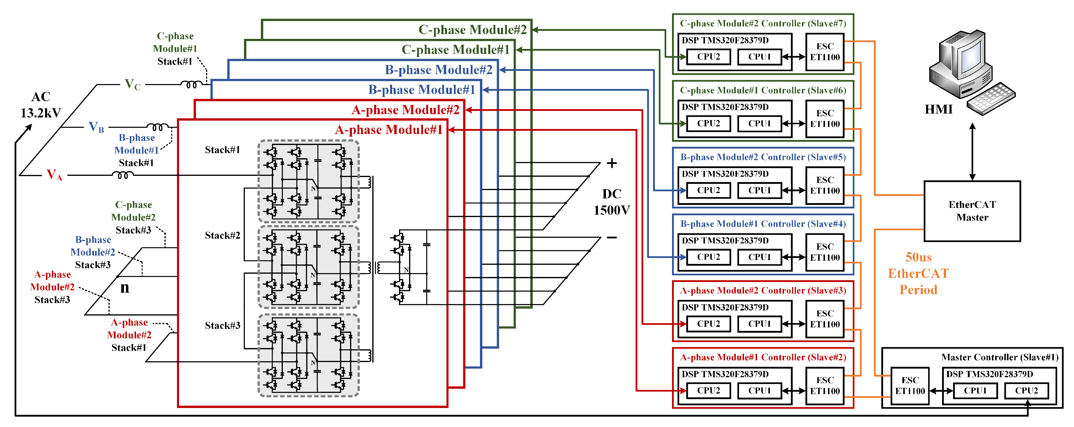
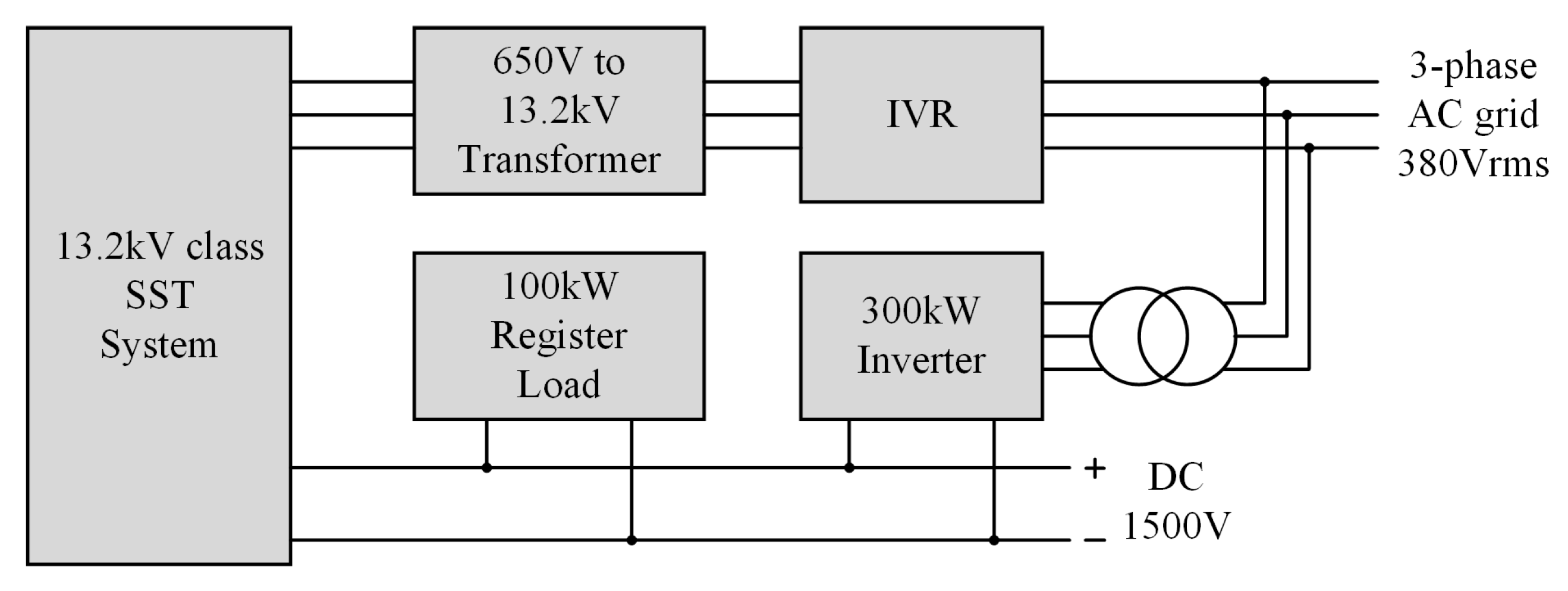
2.3. Configuration of a Proposed 3-Phase Solid State Transformer

Figure 5 describes the structure of the proposed 3-phase SST system based on EtherCAT communication. Each phase of A, B, and C is composed of two unit modules, a total of six unit modules. Each unit module consists of three power stacks that combine the cascaded NPC AC/DC converter stack and the primary side of the QAB converter, and a 4-winding HFIT and the secondary side of the QAB converter. The AC/DC converter of each phase consists of 6 stacks connected in series and has the neutral of the star connection. The secondary side of the QAB converter on six-unit modules is connected in parallel. Each unit module has one unit module controller, and the master controller is present to perform a control algorithm of the AC/DC converter. Master controller and unit module controllers are connected only to EtherCAT communication lines and are configured in a ring topology. Additionally, the EtherCAT master is present for EtherCAT communication. EtherCAT communication will be discussed in the next section.
Figure 6 shows a prototype of the 13.2 kV class 3-phase SST system. The unit module consists of three layers. The first layer consists of two power stacks that combine the AC/DC converter and primary side of the QAB converter. The remaining power stack and inductor are located on the second layer. The third layer consists of an HFIT and the secondary side of the QAB converter. Each unit module controller is located on the back side of the unit module, and each unit module controller is connected only with an EtherCAT cable. Table 3 shows the design specifications of the 13.2 kV class 3-phase SST system prototype.

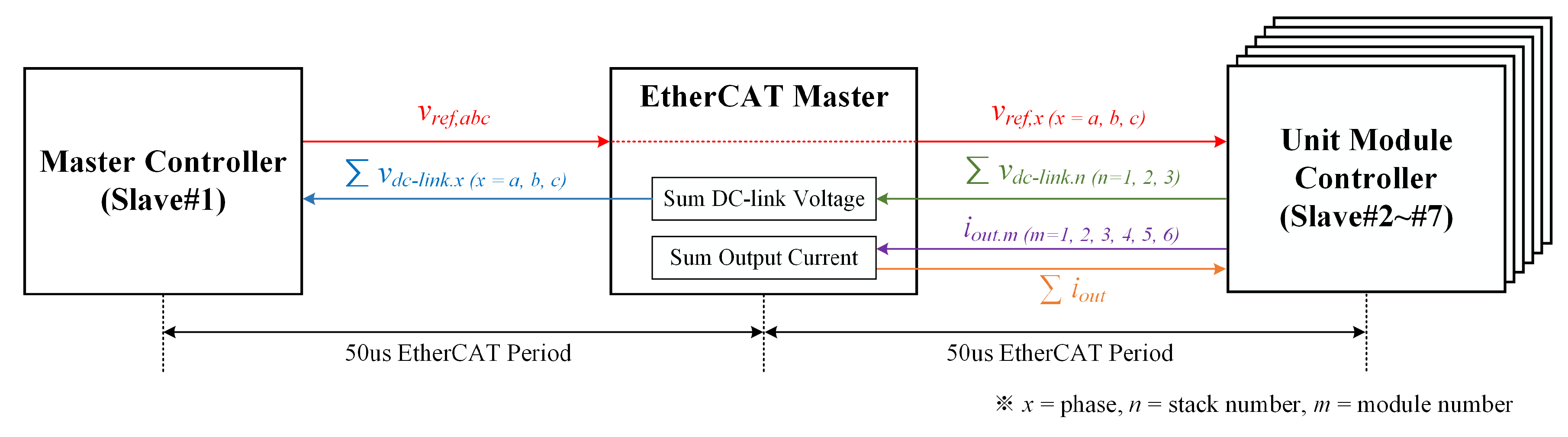
3. EtherCAT Communication Based Control System for a Solid State Transformer

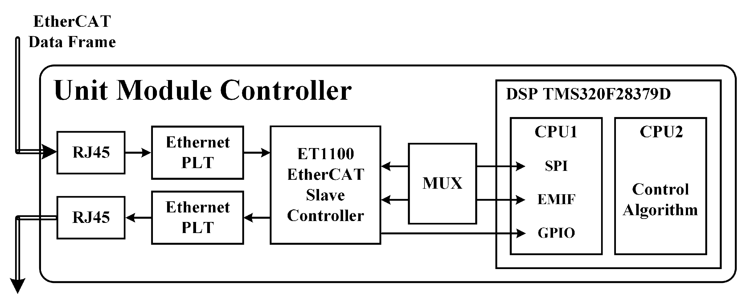
3.1. EtherCAT Communication Using Multi-Core MCU

EtherCAT Slave Controller (ESC) is required for the connection between EtherCAT communication and MCU. ESC is implemented in the form of FPGA or ASIC or as firmware in a subprocessor built into the main processor. In this paper, B e c k h o f f ’s E T 1100 ASIC ESC is used for data interchange between EtherCAT communication and MCU. The E T 1100 and MCU interchange data using an external memory interface (EMIF) or a serial peripheral interface (SPI) as shown in Figure 7. In this case, since a certain amount of time is required to transmit and receive data, there is a limit for single-core MCU to perform both EtherCAT communication and a complicated control algorithm within a high-speed communication cycle [25]. To stably control an SST system composed of a number of unit modules, communication of a high transmission speed is required, and sufficient computational time must be ensured since a complicated control algorithm operation is required. Therefore, in the case of using a multi-core MCU, both high-speed communication cycles and complicated control algorithm execution can be achieved by intentionally separating the EtherCAT communication process and the control application process. By using T I ’s T M S 320 F 28379 D dual-core DSP, CPU1 performs EtherCAT communication and other computations, and CPU2 performs the control algorithm to ensure sufficient computational time in this paper. Figure 7 describes the hardware structure of the unit module controller applied to the prototype of the SST system.

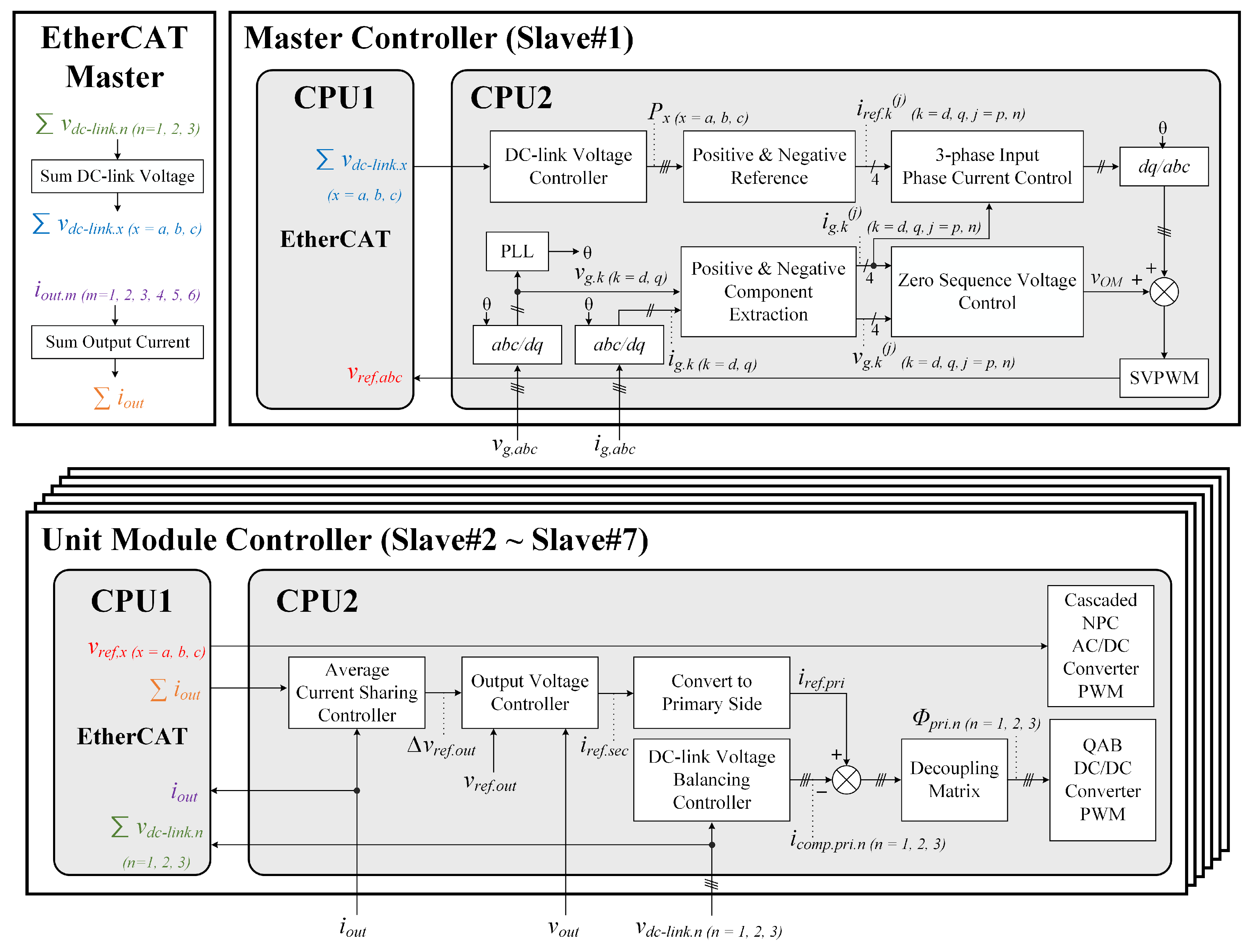
3.2. Control Strategy of the Solid State Transformer Using EtherCAT Communication

Figure 8 describes the control block diagram of the 13.2 kV class 3-phase SST system. Each unit module controller performs the control algorithm of the QAB converter. Since a controller is required to perform the control algorithm of the cascaded NPC AC/DC converter, the entire control system of the proposed SST system has one master controller and six unit module controllers.
The master controller acquires the input voltage and current of the SST system every control cycle. The DC-link voltage of each phase is also required for the master controller to control the cascaded NPC AC/DC converter. The DC-link voltage of the stacks composing the unit module is summed and transmitted to the EtherCAT master, and the total DC-link voltage of each unit module is summed in the EtherCAT master. The total DC-link voltage of each phase is transmitted to the master controller in the next EtherCAT communication cycle. In general, a DC-link voltage controller and an AC input current controller are applied to a synchronous rotating d-q reference frame to achieve a constant DC-link voltage and a sinusoidal input current. However, since there is no power flow exchange between the three phases, a power unbalance occurs between the modules in each phase. To solve this problem, average power control is used to balance the power of each phase module. DC-link balancing control of each phase module is performed using zero-sequence voltage. Although the reference value is transmitted to the data frame of EtherCAT at a 50 µs cycle, it is transmitted to the unit module controllers in the next EtherCAT communication cycle. Therefore, the reference value of the master controller is actually transmitted to the unit module controller at a 100 µs cycle. The unit module controller generates PWM related to the cascaded NPC AC/DC converter with the received reference value.
The unit module controller measures the input/output voltage and current of the QAB converter constituting the unit module. The controller of the QAB converter is mainly composed of three parts. The first part is the output voltage controller. The QAB converter of the individual modules is configured to control the output voltage stably. The second part is the balancing controller between the input voltages. The input stage of the QAB converter is connected to the DC-link of the AC/DC converter. Since the output stage of the AC/DC converter consists of several cascaded structures, an unbalance occurs between DC-link voltages. The input voltage of the QAB converter controls the balance between the input voltages based on the average voltage. The third part is the output stage parallel controller of the QAB DC/DC converter. Converters connected in parallel must share the load current equally. Improper load sharing can lead to converter overload and overheating, which reduces system reliability and ultimately leads to overall system failure. The basic average current programming method among outer loop regulation methods is applied to the active current sharing method for parallel control in this paper. The current for each unit module is shared through EtherCAT communication. The output current transmitted from each unit module is summed in the EtherCAT Master, and the total output current is transmitted to the individual unit modules in the next EtherCAT communication cycle. An average current is calculated based on the shared current. The average current value is set as a reference and configured by the voltage controller along with the current of the individual module.
Figure 9 describes the proposed communication strategy of the SST system. When the EtherCAT frame reaches the master controller, the data transmitted from the master controller to the EtherCAT frame are reference values for each phase, and the data received from the EtherCAT frame to the master controller are the sum of the DC-links of each phase calculated by the EtherCAT master. In the case of the unit module controller, the data transmitted from the unit module controller to the EtherCAT frame are the sum of DC-links of 3 stacks and the output current for output parallel control. The data received from the EtherCAT frame to the unit module controller are the sum of output current and the reference value of the AC/DC converter calculated in the master controller in the previous EtherCAT period. Table 4 shows the EtherCAT data frame configuration of a 13.2 kV class 3-phase SST system. Each data has a size of 2 bytes, and if the data of the master controller and the data of 6 unit module controllers are all combined, the EtherCAT Frame is composed of a data size of 88 bytes. EtherCAT communication is a high-speed communication of 100 Mbps, and theoretically, data of 625 byte size can be transmitted/received within a 50 µs EtherCAT Period. When the proposed EtherCAT frame structure is applied for the purpose of SST system control, theoretically, it is possible to expand up to 50 unit modules. Figure 10 describes the proposed entire control strategy for a 13.2 kV class 3-phase SST using EtherCAT communication.

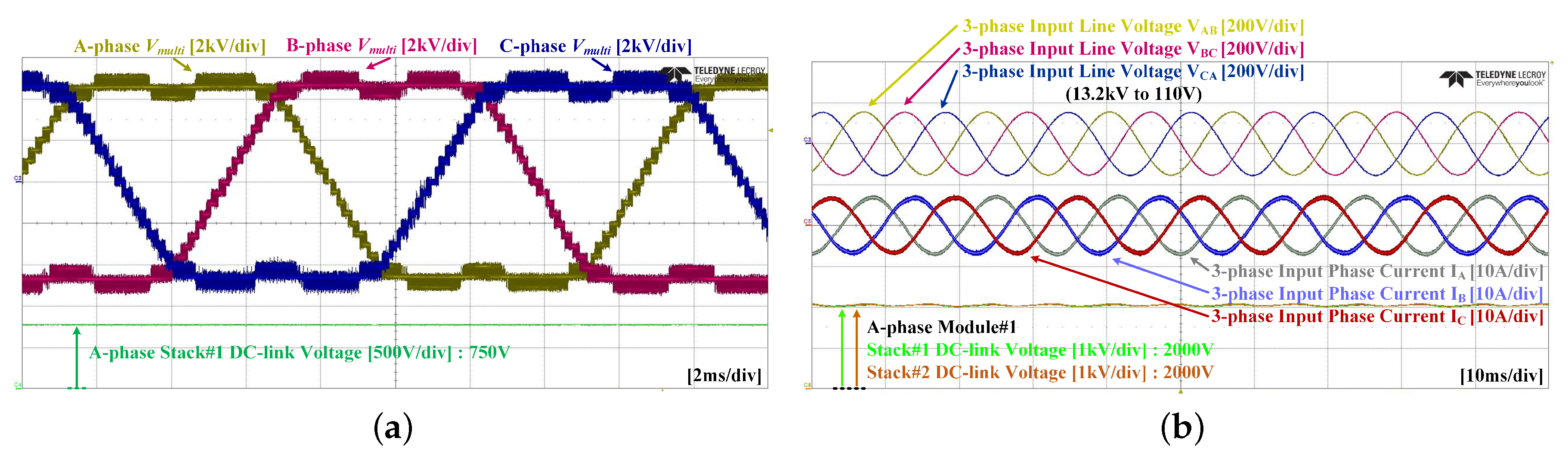
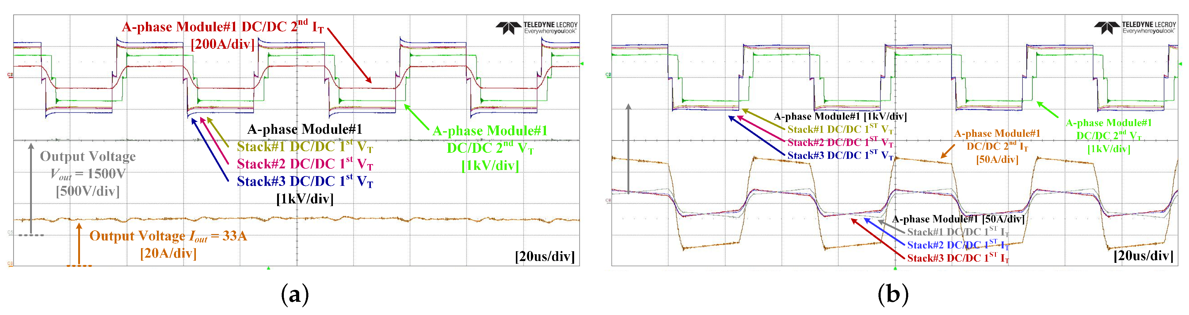
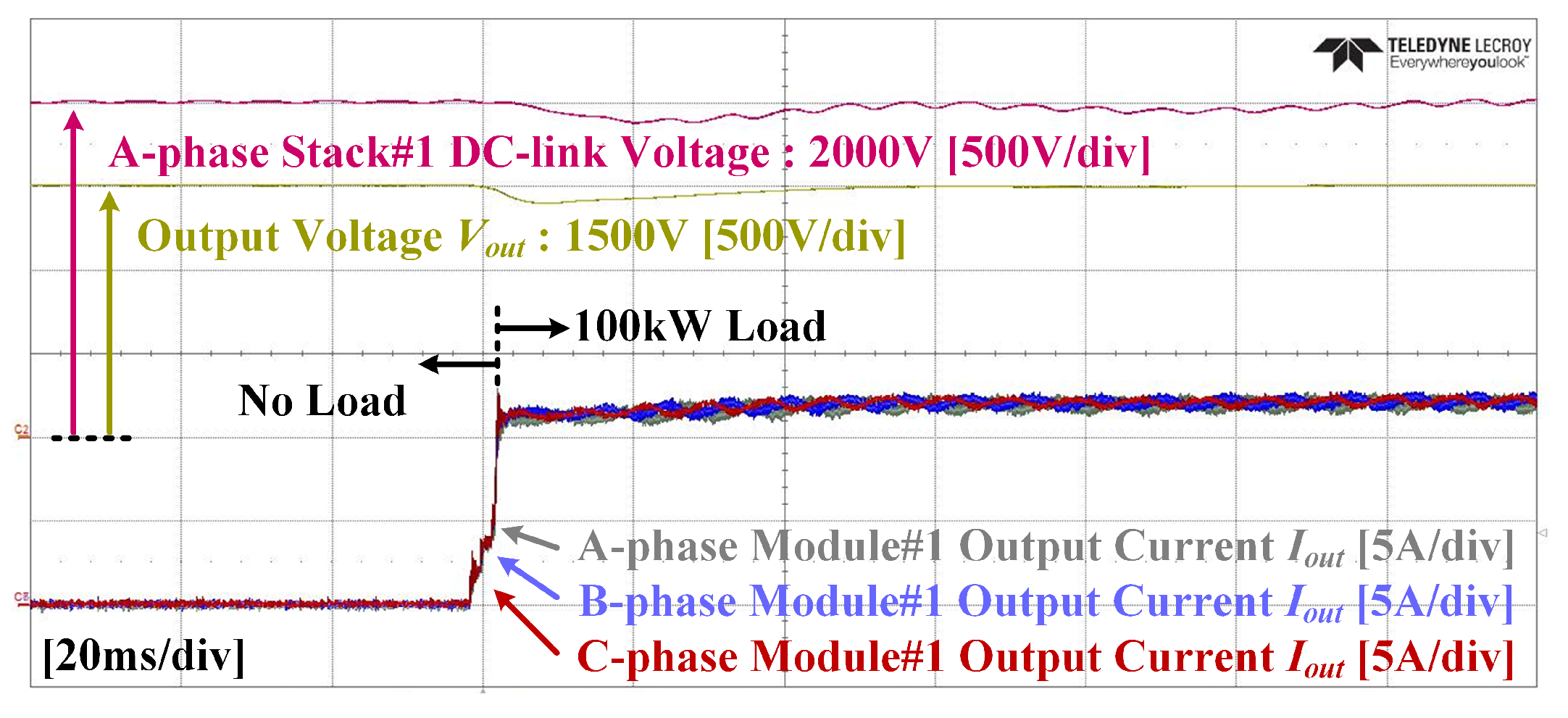
4. Experimental Results

Figure 11 describes the experimental configuration of a 13.2 kV class 3-phase solid state transformer. The general 380 V AC grid is converted into 13.2 kV rated input voltage of the SST system using IVR and 13.2 kV transformer. The 13.2 kV class 3-phase SST system is verified in connection with a resistive load of 100 kW and an inverter of 300 kW.
Figure 12a shows the multi-level voltage and output voltage of the cascaded NPC AC/DC converter in which EtherCAT communication is applied. Due to the limitation of the measurement probe, the experiment is performed at 6.6 k V a c between 3-phase lines. At 6.6 kV grid voltage, the output of the SST is half of the 1.5 kV rated voltage; accordingly, the output voltage is stably controlled with 750 V. Figure 12b shows the line voltage and current of the 3-phase grid in the steady state of the AC/DC converter under the 120 kW load condition. The 13.2 kV line voltage is measured using a potential transformer (PT) with a conversion ratio of 13.2 kV/110 V. The DC-link voltage of Stack#1 and Stack#2 connected in series is controlled to 2 kV stably with a balance under the load condition of 120 kW.
Figure 13 is the experimental waveform of the QAB converter in the unit module under the 50 kW rated load condition. Figure 13a shows that the output voltage of the QAB converter is stably controlled to 1.5 kV under the rated load condition. Figure 13b shows the voltage and current waveforms of a 4-winding HFIT under rated load conditions. Since the input and output of the QAB converter are composed of a half-bridge, a ±1 kV voltage is applied to the primary side of the QAB converter when a 2 kV DC link voltage is applied. When ±1 kV voltage is applied to the three primary sides, ±750 V voltage is applied to the secondary side.
Figure 14 shows the balancing waveform between the output currents at a 100 kW step load. Among the 18 DC-link voltages on the MVDC side, the DC-link of A-phase stack#1, the output voltage of the QAB converter and the output current of the first modules of each phase are measured. A 13.2 kV class 3-phase SST system controls the individual DC-link voltage to 2 kV and the final output voltage to 1.5 kV. Even if a 100 kW step load is applied using a resistive load, each unit module bears the power equally.

5. Conclusions

This paper proposes a 13.2 kV class 3-phase SST system based on EtherCAT communication. Compared to general SST systems that use a DAB converter, a QAB converter can greatly reduce the number of switching elements and transformers, which has the advantage of reducing the volume and cost of the system. In addition, the design of the HFIT is discussed to ensure high dielectric strength in a system of 13.2 kV. To improve control performance and reliability, 50 µs EtherCAT communication is used to control the SST system, and a multi-core MCU is applied to secure sufficient computational time to perform complicated control algorithms. The proposed EtherCAT communication based 13.2 kV class 3-phase SST system has been investigated and verified under various conditions through a prototype of a 300 kW SST system.

Author Contributions

D.-K.J. and H.-S.K. conceptualized the idea of this research project. M.-H.K., H.-S.K., M.-H.R. and J.-W.B. designed the structure and components of 13.2 kV class solid state transformer system. D.-K.J. and H.-S.K. designed and developed a multi-level AC/DC converter. H.-J.Y. and M.-H.K. designed and developed a QAB converter. S.-H.P. and M.-H.R. designed and analyzed an isolated transformer. D.-K.J. developed the EtherCAT communication. The fabrication and experimental setup were mostly carried out by D.-K.J., H.-J.Y. and S.-H.P. under supervision of J.-W.B. The data was analyzed by the team and the paper was written by D.-K.J. and H.-S.K. All authors have read and agreed to the published version of the manuscript.

Funding

This work was supported by the Energy Efficiency and Resources of the Korea Institute of Energy Technology Evaluation and Planning (KETEP) grant funded by the Korea Government Ministry of Knowledge Economy under Grant 20192010106750.

Data Availability Statement

Not applicable.

Acknowledgments

This work was supported by the Energy Efficiency and Resources of the Korea Institute of Energy Technology Evaluation and Planning (KETEP) grant funded by the Korea Government Ministry of Knowledge Economy under Grant 20192010106750.

Conflicts of Interest

The authors declare no conflict of interest.

Abbreviations

The following abbreviations are used in this manuscript:
CANController Area Network
DABDual Active Bridge
EMIFExternal Memory Interface
ESCEtherCAT Slave Controller
HFITHigh-Frequency Isolated Transformer
MCUMicro Controller Unit
NPCNeutral Point Clamped
PTPotential Transformer
QABQuadruple Active Bridge
SCISerial Communication Interface
SPISerial Peripheral Interface
SSTSolid State Transformer

References

  1. Ronan, E.R.; Sudhoff, S.D.; Glover, S.F.; Galloway, D.L. A power electronic-based distribution transformer. IEEE Trans. Power Deliv. 2002, 17, 537–543. [Google Scholar] [CrossRef]
  2. Lai, J.-S.; Maitra, A.; Mansoor, A.; Goodman, F. Multilevel intelligent universal transformer for medium voltage applications. In Proceedings of the Fourtieth IAS Annual Meeting. Conference Record of the 2005 Industry Applications Conference, Hong Kong, China, 2–6 October 2005; Volume 3, pp. 1893–1899. [Google Scholar]
  3. Fan, H.; Li, H. High frequency high efficiency bidirectional DC-DC converter module design for 10 kVA solid state transformer. In Proceedings of the 2010 Twenty-Fifth Annual IEEE Applied Power Electronics Conference and Exposition (APEC), Palm Springs, CA, USA, 21–25 February 2010; pp. 210–215. [Google Scholar]
  4. Fan, H.; Li, H. A novel phase-shift bidirectional DC-DC converter with an extended high-efficiency range for 20 kVA solid state transformer. In Proceedings of the 2010 IEEE Energy Conversion Congress and Exposition, Atlanta, GA, USA, 12–16 September 2010; pp. 3870–3876. [Google Scholar]
  5. Huang, A.Q.; Crow, M.L.; Heydt, G.T.; Zheng, J.P.; Dale, S.J. The future renewable electric energy delivery and management (FREEDM) system: The energy internet. Proc. IEEE 2010, 99, 133–148. [Google Scholar] [CrossRef]
  6. Foureaux, N.C.; Adolpho, L.; Silva, S.M.; Brito, J.A.d.S.; Cardoso Filho, B.d.J. Application of solid state transformers in utility scale solar power plants. In Proceedings of the 2014 IEEE 40th Photovoltaic Specialist Conference (PVSC), Denver, CO, USA, 8–13 June 2014; pp. 3695–3700. [Google Scholar]
  7. Syed, I.; Khadkikar, V. Replacing the grid interface transformer in wind energy conversion system with solid-state transformer. IEEE Trans. Power Syst. 2016, 32, 2152–2160. [Google Scholar] [CrossRef]
  8. Qu, Z.; Yao, Y.; Wang, Y.; Zhang, C.; Chong, Z.; Abu-Siada, A. A novel unbalance compensation method for distribution solid-state transformer based on reduced order generalized integrator. IEEE Access 2019, 7, 108593–108603. [Google Scholar] [CrossRef]
  9. HKimura, N.; Morizane, T.; Iyoda, I.; Nakao, K.; Yokoyama, T. Solid state transformer investigation for HVDC transmission from offshore windfarm. In Proceedings of the 2017 IEEE 6th International Conference on Renewable Energy Research and Applications (ICRERA), San Diego, CA, USA, 5–8 November 2017; pp. 574–579. [Google Scholar]
  10. Huber, J.E.; Kolar, J.W. Solid-state transformers: On the origins and evolution of key concepts. IEEE Ind. Electron. Mag. 2016, 10, 19–28. [Google Scholar] [CrossRef]
  11. Feng, J.; Chu, W.Q.; Zhang, Z.; Zhu, Z.Q. Power electronic transformer-based railway traction systems: Challenges and opportunities. IEEE J. Emerg. Sel. Top. Power Electron. 2017, 5, 1237–1253. [Google Scholar] [CrossRef]
  12. Zhang, X.; Xu, Y.; Long, Y.; Xu, S.; Siddique, A. Hybrid-frequency cascaded full-bridge solid-state transformer. IEEE Access 2019, 7, 22118–22132. [Google Scholar] [CrossRef]
  13. Huang, A.Q.; Zhu, Q.; Wang, L.; Zhang, L. 15 kV SiC MOSFET: An enabling technology for medium voltage solid state transformers. CPSS Trans. Power Electron. Appl. 2017, 2, 118–130. [Google Scholar] [CrossRef]
  14. Madhusoodhanan, S.; Tripathi, A.; Patel, D.; Mainali, K.; Kadavelugu, A.; Hazra, S.; Bhattacharya, S.; Hatua, K. Solid-state transformer and MV grid tie applications enabled by 15 kV SiC IGBTs and 10 kV SiC MOSFETs based multilevel converters. IEEE Trans. Ind. Appl. 2015, 51, 3343–3360. [Google Scholar] [CrossRef]
  15. Tripathi, A.K.; Mainali, K.; Patel, D.C.; Kadavelugu, A.; Hazra, S.; Bhattacharya, S.; Hatua, K. Design considerations of a 15-kV SiC IGBT-based medium-voltage high-frequency isolated DC–DC converter. IEEE Trans. Ind. Appl. 2015, 51, 3284–3294. [Google Scholar] [CrossRef]
  16. Rehman, A.; Ashraf, M. Design and analysis of PWM inverter for 100KVA solid state transformer in a distribution system. IEEE Access 2019, 7, 140152–140168. [Google Scholar] [CrossRef]
  17. Li, Z.; Wang, P.; Chu, Z.; Zhu, H.; Sun, Z.; Li, Y. A three-phase 10 kVAC-750 VDC power electronic transformer for smart distribution grid. In Proceedings of the 2013 15th European Conference on Power Electronics and Applications (EPE), Lille, France, 2–6 September 2013; pp. 1–9. [Google Scholar]
  18. Briz, F.; López, M.; Rodríguez, A.; Zapico, A.; Arias, M.; Díaz-Reigosa, D. MMC based SST. In Proceedings of the 2015 IEEE 13th International Conference on Industrial Informatics (INDIN), Cambridge, UK, 22–24 July 2015; pp. 1591–1598. [Google Scholar]
  19. Glinka, M.; Marquardt, R. A new AC/AC multilevel converter family. IEEE Trans. Ind. Appl. 2005, 52, 662–669. [Google Scholar] [CrossRef]
  20. Jang, Y.-N.; Park, J.-W. Circulating Current Suppression of Hybrid Modular Multilevel Converter with Improved Nearest Level Modulation. In Proceedings of the 2019 34th International Technical Conference on Circuits/Systems, Computers and Communications (ITC-CSCC), JeJu, Korea, 23–26 June 2019; pp. 1–4. [Google Scholar]
  21. Corrêa, T.P.; Almeida, L.; Rodriguez, F.J. Communication aspects in the distributed control architecture of a modular multilevel converter. In Proceedings of the 2018 IEEE International Conference on Industrial Technology (ICIT), Lyon, France, 19–22 February 2018; pp. 640–645. [Google Scholar]
  22. The, A.; Bruening, C.; Dieckerhoff, S. CAN-based distributed control of a MMC optimized for low number of submodules. In Proceedings of the 2015 IEEE Energy Conversion Congress and Exposition (ECCE), Montreal, QC, Canada, 20–24 September 2015; pp. 1590–1594. [Google Scholar]
  23. Wang, D.; Tian, J.; Mao, C.; Lu, J.; Duan, Y.; Qiu, J.; Cai, H. A 10-kV/400-V 500-kVA electronic power transformer. IEEE Trans. Ind. Appl. 2016, 63, 6653–6663. [Google Scholar] [CrossRef]
  24. IEEE Std C57. 12.01-2020; IEEE Standard for General Requirements for Dry-Type Distribution and Power Transformers. IEEE: New York, NY, USA, 2020; pp. 1–49. [Google Scholar]
  25. Maruyama, T.; Yamada, T. Spatial-temporal communication redundancy for high performance EtherCAT master. In Proceedings of the 2017 22nd IEEE International Conference on Emerging Technologies and Factory Automation (ETFA), Limassol, Cyprus, 12–15 September 2017; pp. 1–6. [Google Scholar]
Figure 1. Structure of a unit module: (a) the basic structure of an SST combined in a 1:1 ratio using an AC/DC converter and a DAB converter; (b) a proposed unit module based on a QAB converter.
Electronics 11 03092 g001
Figure 2. Transformer structure: (a) front cross-sectional view; (b) perspective view.
Electronics 11 03092 g002
Figure 3. Electric potential difference: (a) winding structure; (b) electric field simulation results.
Electronics 11 03092 g003
Figure 4. The proposed high-frequency isolation transformer of QAB converter: (a) electric, magnetic, and thermal FEM simulation results; (b) prototype transformer.
Electronics 11 03092 g004
Figure 5. The structure of the proposed 3-phase solid-state transformer based on EtherCAT communication.
Electronics 11 03092 g005
Figure 6. A prototype of a 13.2 kV class 3-phase solid state transformer using EtherCAT communication.
Electronics 11 03092 g006
Figure 7. The structure of the unit module controller.
Electronics 11 03092 g007
Figure 8. Control block diagram of the 13.2 kV class 3-phase solid state transformer system.
Electronics 11 03092 g008
Figure 9. The proposed communication strategy for a 13.2 kV class 3-phase solid state transformer.
Electronics 11 03092 g009
Figure 10. The proposed entire control strategy for a 13.2 kV class 3-phase solid state transformer using EtherCAT communication.
Electronics 11 03092 g010
Figure 11. Experimental configuration of a 13.2 kV class 3-phase solid state transformer.
Electronics 11 03092 g011
Figure 12. Experimental results of cascaded NPC AC/DC converter: (a) multi-level waveform at 3-phase 6.6 k V a c grid line voltage; (b) steady-state waveform under 120 kW load condition.
Electronics 11 03092 g012
Figure 13. Experimental results of the QAB converter under 50 kW rated load condition: (a) steady-state waveform; (b) high-frequency isolation transformer consisting of a 4-winding waveform.
Electronics 11 03092 g013
Figure 14. Experimental results of current sharing under 100 kW step load conditions.
Electronics 11 03092 g014
Table 1. Comparison of unit module components of basic structure and proposed structure.
BasicProposedNumber of Components
Unit ModuleUnit ModuleDifference
Isolated Transformer312
Switching Device48408
Clamp Diode24204
Capacitor1284
Voltage Sensor1284
Current Sensor312
Table 2. Design specifications of the high-frequency isolation transformer.
Rated Power50 kVAFrequency20 kHz
Voltage1 kV (3-Input each)Current20.3 A (3-Input each)
750 V (Output)81.4 A (Output)
Core materialFerrite UU-84No.core3-pair * 2-parallel
Wirespecification0.12 mm, 1100 stands (Pri) Δ B0.359 Tesla
0.12 mm, 3200 stands (Sec)
Turns12:12:12:9Input tubeST-40DG-1
Primary wire tubeGSHS-1635F, 3/8 inchOutput tubeST-80DG-1
Mold materialSylgard-170 A&BBobbin materialTeflon PTFE
Size168 m (L) * 248 m (D) * 184 m (H)Loss
(Rated power)
Total 138.7 W
Table 3. Design specifications of a solid-state transformer system.
ParameterValue
Input voltage ( V g )13.2k [ V A C ]
Output voltage ( V o u t )1.5 [ k V D C ]
Rated power ( P o u t )300 [kW]
Filter inductor ( L f )20 [mH]
DC-link capacitor ( C D C - l i n k )480 [uF]
Output capacitor ( C o u t )560 [uF]
Number of unit power modules6
DC-link voltage ( V D C - l i n k )2 [ k V D C ]
Switching frequency for AC/DC10 [kHz]
Switching frequency for DC/DC20 [kHz]
Turn ratio ( n B i )1:0.6667
Switching device for AC/DCC2M0045170D
Switching device for MVDCC2M0045170D
Switching module for LVDCCAS120M12BM2
Table 4. EtherCAT data frame configuration of a 13.2 kV class 3-phase solid state transformer.
EtherCAT Frame
Master ControllerUnit Module Controller × 6
v r e f . a v r e f . b v r e f . c V d c l i n k . a V d c l i n k . b V d c l i n k . c SequenceMaster
Fault
v r e f . x Unit Module
V d c l i n k
i o u t . m Total
i o u t
SequenceUnit Module
Fault
Publisher’s Note: MDPI stays neutral with regard to jurisdictional claims in published maps and institutional affiliations.

