Tailorable Stimulated Brillouin Scattering Laser Based on Silicon Ring Waveguides
 Yulei Wang1,2
  Kai Li1,2
  Yu Yu1,2,3*
  Sensen Li3
  Yunfei Li1,2
  Wuyue Wang1,2 Changyu Song1,2 Zhiyong Wang1,2
  Gong Wang1,2 Yong Zhang2,4 Zhiwei Lu1,2 Yuhai Li3 Tongyu Liu3 Xiusheng Yan3
- 1Center for Advanced Laser Technology, Hebei University of Technology, Tianjin, China
- 2Hebei Key Laboratory of Advanced Laser Technology and Equipment, Tianjin, China
- 3Science and Technology on Electro-Optical Information Security Control Laboratory, Tianjin, China
- 4School of Science, Hebei University of Technology, Tianjin, China
Stimulated Brillouin scattering (SBS) lasers based on silicon waveguides with large SBS gain, have been widely used in frequency tunable laser emission, mode-locked pulse laser, low-noise oscillator, optical gyroscope, and other fields. However, current SBS lasers still need long waveguide lengths to realize Brillouin laser output, which increases the waveguide losses and is not conductive to be integrated. In this paper, we propose a silicon ring waveguide, in order to tune the frequency of the phonon field of SBS laser based on the silicon substrate of the ring cavity. The simulation results exhibit that the tailorable forward SBS effect is realized in the silicon-based optical waveguide with a large SBS gain up to 1.90 W-1m-1. Particularly, with the mutual restraint between photoelastic and moving boundary effects, the tunable phonon frequencies emitting from 1 to 15 GHz are realized through the conversion among higher order modes by modifying the widths of the ring cavity. Therefore, this silicon waveguide based on ring cavity will provide a new technical scheme for designing tunable SBS lasers by tuning the ring widths. In addition, this enhanced and broadband acoustic radiation will pave the way for hybrid integration in silicon-based optical waveguide, micro-electromechanical system, and CMOS signal processing technology.
Introduction
Stimulated Brillouin scattering (SBS) effect is a third-order nonlinear effect, which is produced by the interaction of photons with phonons in the medium [1–3]. The SBS effect can be exploited to realize the conversion from optical waves (with higher frequency) to acoustic waves. Various applications based on the SBS effect, such as distributed sensing [4,5], slow light and fast light [6,22], microwave photonics [7–9], and narrow line width Brillouin lasers [10,11], have gained tractions and developped rapidly for decades. However, the realization of the SBS effect based on traditional waveguides such as optical fiber requires length of several kilometers, which makes the entire experimental device more complex and is not conducive to miniaturization and integration. The SBS effect can be realized by using microstructures; while the main reported platforms are micro resonant cavity, sulfur waveguide, and silicon-based waveguide, respectively.
If the optical gain generated by SBS exceeds the round-trip loss, SBS lasing will occur. Particularly, as a kind of nonlinear photo-acoustic coupling, the SBS effect is significant and can surpass Kerr and Raman interaction effects in most transparent media [12]. Due to the phonon dissipation induced by the substrate, the integrated silicon waveguide with enhanced Raman and Kerr nonlinearity tends to produce tiny SBS coupling. However, it is difficult for acoustic waves to be guided in a pure silicon on insulator (SOI) waveguide on account of the high intensity in silicon, i.e., the high speed of phonons. This will greatly inhibit the interaction between photons and phonons, which leads to a decrease of SBS effect in SOI. In order to excite the strong photon-phonon interaction in SOI, different structures of silicon-based optical waveguides were further proposed, including silicon ridge [13], suspended silicon waveguide membrane [14,15], silicon disk [16], silicon ring [17], and silicon bullseye [18]. Independent control of acoustic and optical characteristics is allowed, since optical and acoustic modes are limited by different physical mechanisms. SOI provides a stable platform for on chip nonlinear optical processing, which makes it effective in integrated system. Several structures have been fabricated in order to enhance the nonlinear effect, such as suspended waveguide, photonic crystal waveguide, ring waveguide, disk waveguide, and so on, so that the laser output based on forward stimulated Brillouin scattering (FSBS) can be realized in a smaller device size. However, the length of ridged waveguide is always several centimeters [19], which is not easy to be integrated and makes the processing of the target center and disk waveguide more complex. Therefore, there is still a need for a more local method to obtain enhanced SBS gain and high Q value in a limited area, especially for the forward Brillouin scattering in a compact-designed on-chip waveguide system.
In this paper, we demonstrate a Brillouin laser in silicon by using a ring guided wave forward Brillouin scattering (called stimulated multimode Brillouin scattering), in which the coupled light field is coupled in different optical spatial modes. By adjusting the ring width, the acoustic frequency is tuned and the SBS gain is increased. This work represents an imperative step in the field of designing SBS laser and paves the way for hybrid integration in silicon-based optical waveguide, micro-electromechanical system, and CMOS signal processing technology [6].
Theory Model
In the process of SBS effect, the pump light with frequency wp interferes with the Stokes light with frequency ws (ws < wp), resulting in a light force distribution that varies with time and space; while the beat frequency produces the phonon signal with frequency Ω. In SBS process, the phase matching condition should be satisfied, that is, the conservation of momentum and energy should be satisfied as follows [18],
where,
It is assumed that the electric field distribution of the pump pulse and Stokes pulses satisfies the following relationships:
Using the small signal approximation, assuming that the pump power in the waveguide is greater than the Stokes signal power, the coupling between the pump light and the Stokes signal light should meet the following requirements:
where,
where,
where the subscript m is the m-order acoustic mode (m = 1,2,3...).
Considering the acoustic loss, the peak value of SBS gain spectrum can be simplified as follows:
where, vgs,
The acoustic displacement field is caused by the total optical force and should meet the phase matching conditions of Eq. 1 and Eq. 2. In order to calculate um, the elastic loss can be neglected in isotropic medium, and the ideal acoustic equation should satisfy as follows:
where, Cijkl represents photoelastic tensor, ui and fi are displacement component and total light force of phonon field, respectively. The equation is the derivative along the j-th space direction of j, in which
To further clarify Eq. 9, Eq. 9 can be rewritten as:
where,
Simulation Results
As shown in Figure 1A, the Brillouin silicon laser system is made of a silicon wafer on a single crystal insulator, which is composed of a ring-shaped silicon runway resonance cavity. In the whole device, the light is fully reflected in the ring-shaped waveguide cavity. The design diagram of the ring cavity Brillouin laser is shown in Figure 1B. The silicon thickness is t = 250 nm, and the ring width is w = 500–2000 nm. The displacement field related to each phase matched Brillouin active waveguide mode is shown in Figure 1C. In the forward mode Brillouin scattering on the ring cavity, the phase matching condition satisfying m = 0 is shown in Eqs 1, 2. This multimode waveguide provides low loss guidance for different types of spatial modes [with their own propagation constants k1 (red line) and k2 (blue line)], resulting in different high quality factor (Qm) cavity modes with slightly different free spectral range (FSR). The phase matching condition shall meet the matching of energy and frequency as shown in Figure 1C. Under the condition of ks > 0 and kp > 0, since the same propagation direction of the pump and Stokes pulses, these two values are very close. Therefore, the wave vector size of the phonon wave will be quite small, which causes the axial displacement of the phonon field to be extremely weak and the lateral displacement to dominate. In order to allow the phonon field to interact with the photon field long enough, the transverse phonon mode must be well confined to the waveguide medium. Therefore, the ring structure has been fabricated in Figure 1A. Most of the silicon is exposed to the air with a small part connected to the silicon dioxide. Since the refractive index of silicon differ widely with that of air, the light field has been restricted effectively. At the same time, owing to the higher speed of sound in silicon than that in air, the leakage of phonons is also effectually prevented. Besides, traditional waveguide media, such as optical fibers, have a long limitation on the transverse phonon field. This is why only BSBS can be observed in ordinary fiber waveguides. Meanwhile, the mutual conversion of electric field distribution with different modes can generate multi-mode transmission spectrum with multiple characteristic frequencies. As shown in Figure 1D, when the pump light excites the silicon ring waveguide, the Stokes signal light and the acoustic signal with beat frequency signal will be generated. The frequency detuning of the pump wave and Stokes wave results in the mismatch of the wave vector k, caused by the dispersion of the waveguide mode.
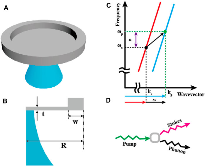
FIGURE 1. (A) Structural diagram of micro ring cavity system. (B) Design drawing of ring cavity: t = 250 nm, w = 100 nm, Si radius corresponding to R = 5 µm. (C) Schematic diagram of the optical dispersion diagram. The optical resonance is represented by discrete points (black and blue) along the overall dispersion curve. The lower arrow indicates the resonance optical transition from pump light (kp) to Stokes light mode (ks) due to SBS. (D) When the optical frequency matches the mechanical acoustic mode, the phase matching and energy conservation of Stokes process are described by the photon density of state (PDOS) and the acoustic frequency Ω.
Due to the two edge constraint mechanisms of electrostriction effect and moving boundary effect, circular waveguide resonators with different width can be analyzed, as shown in Figure 2A. Because the refractive index of silicon at 1,550 nm is particularly high, the transverse size and thickness of floating ring structure can reach several hundred nanometers. The distribution of the pump electric field is shown in Figure 2B. In the process of forward SBS effect, the strong constraint on photon wave and elastic phonon wave also increases the disturbance of photoelastic effect (PE) and moving boundary effect (MB). Figure 2C shows the dispersion curves of all acoustic modes satisfying the phase matching condition of forward scattering between modes of Eqs 1, 2. As shown in Figure 2C, a red color indicates a larger photo mechanical coupling (dark blue indicates zero photo mechanical coupling). It is worthy to note that the existence of quasi band gap (the frequency range of phonon waves with high reflectivity) not only limits the acoustic mode to the position towards the edge of the disk, but also increases the optical mechanical coupling and optical mode due to the large overlap between δεrr. In Figure 2C, we also show the spatial profile of the main photoelastic and moving boundary components of the radial breathing sample mechanical mode in the whole circular cavity structure. Although there is a symmetrical fracture in the z-direction (the grating strut is along the bottom of the disk), which results in a radial ur and a vertical uz displacement coupling, there is no significant difference in the origin of the optomechanical coupling. These analyses can be easily applied to other crystals and composites to form a target cavity. All mechanical modes coupled to TE optical mode by PE and MB perturbations are calculated using Eq. 3. The corresponding spectrum is normalized such that its peak height is proportional to the total optomechanical coupling rate. Clearly only one mode family, namely the breathing mode, is dominant in this case. Assuming that the phonon wave is limited by the width of the ring and the velocity of the longitudinal wave V1 in the silicon disk, the frequencies of different modes of phonon waves can be estimated. Multiple orders of the acoustic modes are given by Ωp = pVl/(2w), where Vl = 9,660 m/s, and p is the integer representing the order of the mode. The red dotted lines in Figure 2C represent these estimated frequency dispersion curves as a function of the ring width of the order p in each mode. The correct design of ring and acoustic mode sequence can be used to enhance photo-acoustic coupling or automatically cancel photo-acoustic coupling. As shown in Figure 2D, when the waveguide width is 1,750 nm, there are six acoustic modes (m = 6) in the ring cavity under the photoelastic effect and moving boundary effect. In particular, the efficiency of optomechanical coupling between the first-order acoustic breathing mode and the optical mode is improved. In this case, because the maximum strain component almost completely overlaps with the optical mode, a large coupling efficiency can be achieved.
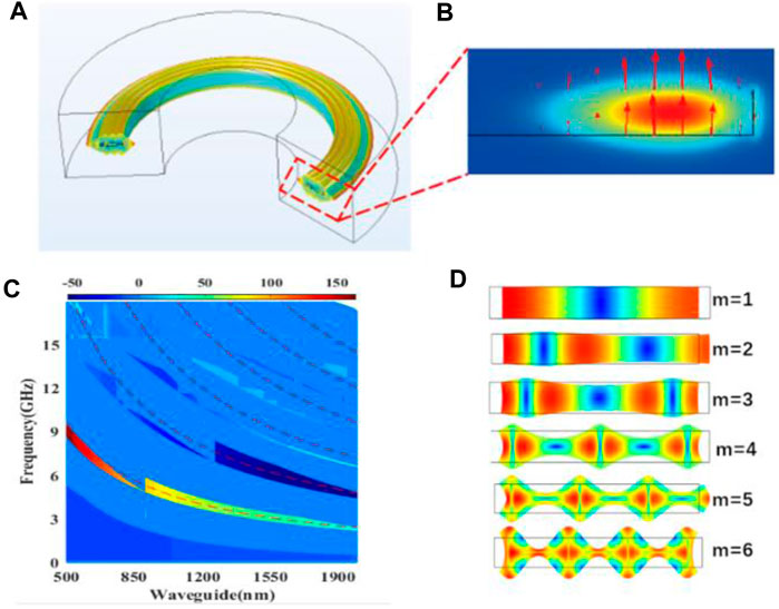
FIGURE 2. (A) A model of photo-acoustic interaction in an annular cavity, in which the thickness of the silicon layer is 250 nm and the radius of the annular cavity is 10 μm. (B) The electric field distribution of the pump light when the width is w = 1,750 nm. (C) The finite element simulation of the change of the photo-acoustic coupling rate with the section width in the annular cavity structure, and the red dotted line is the frequency calculated according to the multi-order mode of Fabry Perot. (D) When the width is 1,750 nm, the pattern distribution of each sub mode (red dot) that satisfies the phase matching determined in c is shown. Each mode (m = 1, 2, ..., 6) is marked according to the pattern index c.
On the other hand, for the coupling between the third-order breathing mode and the surrounding TE mode, there is a competition between photoelastic effect and moving boundary effect. The product of boundary and volume has the opposite phase to the geometry, which leads to the self-cancellation effect. In addition, in the mode forward scattering state, a simple ring cavity is not enough to limit the elastic phonon wave to the edge of the ring [20]. discussed a method of using the target core structure to limit the phonon wave to the edge of the disk [20].
By finite element simulation, the curve of the nonlinear Brillouin optical acoustic coupling efficiency with frequency of the ring waveguide with different width is obtained. The resonant Brillouin generated by multiple ring waveguides as shown in Figure 3, is w = 0.5, 0.75, 1.0, 1.25, 1.5 and 1.75 μm, respectively. The characteristic frequency of each Brillouin active phonon mode (pentagram star) can be calculated with the change of waveguide size w, and each trace satisfying the characteristic frequency can be obtained. Each waveguide has a resonant mode marked with mode index m.
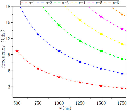
FIGURE 3. The relationship between the coupling efficiency and the frequency in the Brillouin ring laser with the variation of waveguide width w.
As can be seen from Figure 3, each waveguide will generate a series of regular interval Brillouin resonance, clear signal can be observed, showing nonlinear Brillouin response. As shown in Figure 2C, only the phonon mode with uniform displacement symmetry relative to the waveguide core can produce effective Brillouin coupling due to the spatial symmetry of optical force distribution. When the Brillouin spectrum changes with the waveguide size, different resonance features are color coded (red, blue, green, etc.) to indicate the mode order of each phonon resonance (first, second, third, etc.). As shown in Figure 4, the change in cavity size allows for precise brucellian resonance at almost any frequency from 1 to 15 GHz, enabling unprecedented nonlinear tunability. For example, when the cavity size w changes from 1,750 to 500 nm, the first-order acoustic mode (m = 1) resonates (red). In this case, because the maximum strain component overlaps the optical mode to almost the same degree, a large coupling efficiency can be achieved. The acoustic frequency changes from 3.2 to 9.3 GHz, at which a strong Brillouin resonance occurs.
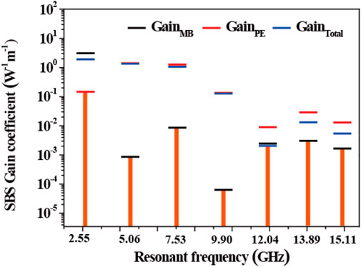
FIGURE 4. The contribution of different effects to SBS gain coefficient in the process of stimulated Brillouin scattering when waveguide width w = 1,750 nm, including the contribution of moving boundary effect (black short line), radiation pressure effect (red short line), and the whole Brillouin gain (blue short line).
In order to accurately determine the Brillouin nonlinear coefficient GSBS with respect to the intrinsic Kerr nonlinear coefficient GK and the nonlinear free carrier dispersion coefficient GFC, the nonlinear coupled amplitude equation is formulated as: the power forms of Stokes and anti-Stokes line shapes are derived. Because SBS is a kind of resonance effect, its nonlinear coefficient presents a Lorentz shape centered on each Brillouin active phonon mode. In contrast, the electron Kerr nonlinearity is non resonant at the wavelength of 1,550 nm, resulting in a frequency independent nonlinear coefficient. As Wang et al. did in the fiber-based study [21], the frequency-dependent interference between Kerr and Brillouin effects produced an asymmetric (Fano like) alignment. It should be noted that our simulations are quite different, resulting in a different set of coupled amplitude equations. In addition, under our simulated conditions, the nonlinear free carriers in silicon are the reason for the different order of Stokes and anti-Stokes, and the influence of the nonlinear background is greater for frequencies below 2 GHz. When the free carrier effect decays at high frequency, the 16 GHz Kerr response is used as a reference to determine the amplitude of Brillouin nonlinear coefficient. Using the resonance characteristics in Figure 3, the size of the Brillouin nonlinear coefficient GSBS can be obtained. According to the electron Kerr nonlinear effect, the interference at Stokes and anti-Stokes frequencies is caused by the cross phase modulation between the pump beam and the probe beam in the silicon waveguide core.
In the optical waveguide structure on silicon substrate, the linear sum of all the overlapping integrals between a single optical force (fn) and a single m-order acoustic eigenmode in the process of optical mechanical coupling can be expressed as follows:
It is worth noting that the contribution of a single overlapping integral depends on the light force, and their relative phases are directly affected by the interference effect. In order to calculate Eq. 9 and obtain the SBS gain coefficient in the nanometer optical waveguide, we need to consider two main factors: the electrostrictive force and the radiation pressure, namely FTotal = FPE + FMB. Electrostriction is the secondary response of mechanical strain excited by external electric field. The i-th component of the electrostrictive force is defined as:
where,
where,
The electrostrictive force is given by the divergence of electrostrictive tensor. In a system consisting of domains of homogeneous materials, electrostrictive forces can exist inside each material (producing an electrostriction body force), and at interfaces where discontinuous stresses are present (yielding an electrostrictive pressure). From the divergence of Eq. 16, the electrostrictive body force become FPEei(qx-Ωt), with vector components:
The gradient of
For the waveguide with constant horizontal direction, only the transverse component of the force can contribute to the SBS gain coefficient.
This strong photon phonon coupling is produced by a constructive combination of PE force and nanometer radiation pressure. Large radiation pressure induced coupling represents new forms of boundary induced Brillouin nonlinearity and boundary mediated Brillouin coupling in subwave length structure. This novel waveguide geometry can independently control the phonon mode and the driving force of the opto mechanical system, thus creating a customizable Brillouin coupling over a wide bandwidth. The simulation results show that the tunable forward SBS effect is realized in the silicon-based optical waveguide with a larger SBS gain of 1.90 W-1m-1, The higher SBS gain excites high-power phonons, as a result, the tunable phonon frequency from 1 to 15 GHz is realized.
Conclusion
In this contribution, we have developed a waveguide system on silicon substrate, and proposed a Brillouin laser with ring cavity waveguide structure. By using the larger refractive index and better photoelastic component of silicon material, the tuning of SBS acoustic field signal frequency were realized by adjusting the ring section width and enhancing the forward SBS effect of main drive. Multi physical field simulation demonstrates that the strong photon phonon coupling is produced by the constructive combination of PE force and nanometer radiation pressure. The emergence of large radiation pressure induced coupling represents new forms of boundary induced Brillouin nonlinearity and boundary mediated Brillouin coupling in subwavelength structure. This novel waveguide geometry can independently control the phonon mode and the driving force of the optomechanical system, thus creating a customizable Brillouin coupling over a wide bandwidth. According to the radiation pressure effect and the boundary moving effect, the SBS laser with the ring cavity structure shows a larger SBS gain (up to 1.90 W-1 m-1), which is 100 times of the reported SBS gain. Coupled to massive transverse phonon modes, a relatively flat Brillouin gain can be generated over the entire 1–15 GHz frequency range. Therefore, the photon-phonon conversion based on Brillouin nonlinear effect can be realized through guiding and manipulating the phonons emitted by Brillouin on chip. This work opens up new possibilities in the field of CMOS and MEMS by the mixing of Brillouin device physics with silicon photons [22].
Data Availability Statement
The original contributions presented in the study are included in the article/Supplementary Files, further inquiries can be directed to the corresponding author.
Author Contributions
YW and KL: Data curation, Writing- Original draft preparation, Software, and Validation; YY: Conceptualization, Methodology, and Software; SL: Visualization and Investigation; YL: Writing- Reviewing and Editing; WW, CS and ZW: Visualization and Investigation; GW, YZ and ZL: Editing.
Funding
This work was supported by the National Natural Science Foundation of China (Grant Nos. 62005074, No. 61927815, No. 62075056 and No. 6142107200313), and Key Laboratory Fund Project (No. 61421070302).
Conflict of Interest
The authors declare that the research was conducted in the absence of any commercial or financial relationships that could be construed as a potential conflict of interest.
Publisher’s Note
All claims expressed in this article are solely those of the authors and do not necessarily represent those of their affiliated organizations, or those of the publisher, the editors and the reviewers. Any product that may be evaluated in this article, or claim that may be made by its manufacturer, is not guaranteed or endorsed by the publisher.
References
1. Shin H, Qiu W, Jarecki R, Cox JA, Olsson RH, Starbuck A, et al. Tailorable Stimulated Brillouin Scattering in Nanoscale Silicon Waveguides. Nat Commun (2013) 4:1944. doi:10.1038/ncomms2943
2. Clarke JT, Gérard J-C, Grodent D, Wannawichian S, Gustin J, Connerney J, et al. Morphological Differences between Saturn's Ultraviolet Aurorae and Those of Earth and Jupiter. Nature (2005) 433:717–9. doi:10.1038/nature03331
3. Zhu Z, Gauthier DJ, Boyd RW. Stored Light in an Optical Fiber via Stimulated Brillouin Scattering. Science (2007) 318:1748–50. doi:10.1126/science.1149066
4. Stiller B, Foaleng SM, Beugnot J-C, Lee MW, Delqué M, Bouwmans G, et al. Photonic crystal Fiber Mapping Using Brillouin Echoes Distributed Sensing. Opt Express (2010) 18:20136–42. doi:10.1364/OE.18.020136
5. Sanghoon Chin S, Primerov N, Thevenaz L. Sub-Centimeter Spatial Resolution in Distributed Fiber Sensing Based on Dynamic Brillouin Grating in Optical Fibers. IEEE Sensors J (2012) 12:189–94. doi:10.1109/JSEN.2011.2126568
6. Boyd RW, Gauthier DJ. Controlling the Velocity of Light Pulses. Science (2009) 326:1074–7. doi:10.1126/science.1170885
7. Chin S, Thévenaz L, Sancho J, Sales S, Capmany J, Berger P, et al. Broadband True Time Delay for Microwave Signal Processing, Using Slow Light Based on Stimulated Brillouin Scattering in Optical Fibers. Opt Express (2010) 18:22599–613. doi:10.1364/OE.18.022599
8. Sancho J, Sanghoon Chin S, Sagues M, Loayssa A, Lloret J, Gasulla I, et al. Dynamic Microwave Photonic Filter Using Separate Carrier Tuning Based on Stimulated Brillouin Scattering in Fibers. IEEE Photon Technol Lett (2010) 22:1753–5. doi:10.1109/LPT.2010.2082514
9. Sancho J, Primerov N, Chin S, Antman Y, Zadok A, Sales S, et al. Tunable and Reconfigurable Multi-Tap Microwave Photonic Filter Based on Dynamic Brillouin Gratings in Fibers. Opt Express (2012) 20:6157–62. doi:10.1364/OE.20.006157
10. Gundavarapu S, Brodnik GM, Puckett M, Huffman T, Bose D, Behunin R, et al. Sub-hertz Fundamental Linewidth Photonic Integrated Brillouin Laser. Nat Photon (2019) 13:60–7. doi:10.1038/s41566-018-0313-2
11. Tow KH, Léguillon Y, Besnard P, Brilland L, Troles J, Toupin P, et al. Relative Intensity Noise and Frequency Noise of a Compact Brillouin Laser Made of As_38Se_62 Suspended-Core Chalcogenide Fiber. Opt Lett (2012) 37:1157–9. doi:10.1364/OL.37.001157
12. Pettit RM, Ge W, Kumar P, Luntz-Martin DR, Schultz JT, Neukirch LP, et al. An Optical Tweezer Phonon Laser. Nat Photon (2019) 13:402–5. doi:10.1038/s41566-019-0395-5
13. Yang KY, Oh DY, Lee SH, Yang Q-F, Yi X, Shen B, et al. Bridging Ultrahigh-Q Devices and Photonic Circuits. Nat Photon (2018) 12:297–302. doi:10.1038/s41566-018-0132-5
14. Schmidt MK, Poulton CG, Mashanovich GZ, Reed GT, Eggleton BJ, Steel MJ. Suspended Mid-infrared Waveguides for Stimulated Brillouin Scattering. Opt Express (2019) 27:4976–89. doi:10.1364/OE.27.004976
15. Otterstrom NT, Behunin RO, Kittlaus EA, Wang Z, Rakich PT. A Silicon Brillouin Laser. Science (2018) 360:1113–6. doi:10.1126/science.aar6113
16. Espinel YAV, Santos FGS, Luiz GO, Alegre TPM, Wiederhecker GS. Brillouin Optomechanics in Coupled Silicon Microcavities. Sci Rep (2017) 7:43423. doi:10.1038/srep43423
17. Mirnaziry SR, Wolff C, Steel MJ, Morrison B, Eggleton BJ, Poulton CG. Lasing in Ring Resonators by Stimulated Brillouin Scattering in the Presence of Nonlinear Loss. Opt Express (2017) 25:23619–33. doi:10.1364/OE.25.023619
18. Wiederhecker GS, Dainese P, Mayer Alegre TP. Brillouin Optomechanics in Nanophotonic Structures. APL Photon (2019) 4:071101. doi:10.1063/1.5088169
19. Otterstrom NT, Behunin RO, Kittlaus EA, Rakich PT. Optomechanical Cooling in a Continuous System. Phys Rev X (2018) 8:041034. doi:10.1103/PhysRevX.8.041034
20. Santos FGS, Espinel YAV, Luiz GO, Benevides RS, Wiederhecker GS, Mayer Alegre TP. Hybrid Confinement of Optical and Mechanical Modes in a Bullseye Optomechanical Resonator. Opt Express (2017) 25:508–29. doi:10.1364/OE.25.000508
21. Wang J, Zhu Y, Zhang R, Gauthier DJ. FSBS Resonances Observed in a Standard Highly Nonlinear Fiber. Opt Express (2011) 19:5339–49. doi:10.1364/OE.19.005339
Keywords: fiber optics, optical communications, optical solitons, nonlinear optics, optical waveguide
Citation: Wang Y, Li K, Yu Y, Li S, Li Y, Wang W, Song C, Wang Z, Wang G, Zhang Y, Lu Z, Li Y, Liu T and Yan X (2021) Tailorable Stimulated Brillouin Scattering Laser Based on Silicon Ring Waveguides. Front. Phys. 9:749880. doi: 10.3389/fphy.2021.749880
Received: 30 July 2021; Accepted: 06 September 2021;
Published: 24 September 2021.
Edited by:
Zhongquan Nie, Taiyuan University of Technology, ChinaReviewed by:
Yi Liu, Taiyuan University of Technology, ChinaXuehua Zhu, Anhui Polytechnic University, China
Copyright © 2021 Wang, Li, Yu, Li, Li, Wang, Song, Wang, Wang, Zhang, Lu, Li, Liu and Yan. This is an open-access article distributed under the terms of the Creative Commons Attribution License (CC BY). The use, distribution or reproduction in other forums is permitted, provided the original author(s) and the copyright owner(s) are credited and that the original publication in this journal is cited, in accordance with accepted academic practice. No use, distribution or reproduction is permitted which does not comply with these terms.
*Correspondence: Yu Yu, yuyu1990@hebut.edu.cn