Study on Coal Pillar Size Design Based on Non-integral Contact Structure of Coal and Rock Under Static and Dynamic Loads
 Qinghai Li
 Jingkai Li
 Zhiqiang Wang
 Kaixin Li
 Cunzhi Zhang
- 1College of Energy and Mining Engineering, Shandong University of Science and Technology, Qingdao, China
- 2School of Energy and Mining Engineering, China University of Mining and Technology, Beijing, China
- 3College of Geodesy and Geomatics, Shandong University of Science and Technology, Qingdao, China
Reasonable coal pillar size of roadway protection is an important guarantee for roadway stability under the action of static-dynamic coupling loadings in deep mines. Coal pillar and roof-floor rock form a non-integral contact structure of coal and rock. However, in the existing literature, there is no research on the size of the coal pillar under static-dynamic coupling loadings based on the non-integral contact structure of coal and rock. In this study, the coal-rock non-integral contact composite specimens are designed, and the coal pillar size is simulated by the radial sizes of the specimens. The failure characteristics of coal-rock under the static-dynamic coupling loadings are studied by the SHPB test, which provides the basis for the design of coal pillar size, and finally determines the reasonable coal pillar size by combining with numerical simulation. The test results show that the strength of the specimens decreases with the decrease of section size of coal and increases with the increase of dynamic load, but there is a critical value for static load. When the coal sections radial sizes are 50, 45, and 40 mm and dynamic loads are applied, the stress-strain curve of the specimens has a plastic stage, but the rest do not exist. The minimum coal section radial size which can ensure the stability of the specimens is 40 mm, and the similar calculation of coal pillar size is 88 m. Combined with numerical simulation, the final coal pillar size is 90 m. This study provides a more accurate and reliable method to determine the size of a coal pillar under the action of static-dynamic coupling loadings.
Introduction
With the depletion of shallow resources, underground mining of coal mines has gradually gone deeper, and there are more than 100 mines in the world’s major coal mining countries with a mining depth of more than 1000 m (Zhang et al., 2019). The maximum mining depth in Germany has reached 1713 m (Pan et al., 2020), and there are more than 50 mines with a mining depth exceeding 1000 m in China (Huang et al., 2020). With the increase of mining depth, the instability of the roadway is widespread, so the coal pillar for roadway protection is an effective guarantee for roadway stability (Li et al., 2019). In the complex geological environment of deep mines, coal pillars are not only subjected to long-term effects of high static loads, but also frequently subjected to impact dynamic loads. Under static-dynamic coupling loadings, coal and rock show more obvious nonlinear and discontinuous mechanical characteristics, which also puts forward new requirements for the coal pillar’s size (Kumar et al., 2019; Liu et al., 2020; Zhang et al., 2020). Therefore, it is of great significance to study the failure characteristics of coal and rock under static-dynamic coupling loadings and to set a reasonable coal pillar size for roadway protection.
When studying coal pillar size, predecessors mainly considered the influence of coal seam mining height (Kong et al., 2014), coal strength (Poulsen et al., 2014), coal seam dip angle (Damghani et al., 2019), buried depth (Kumar et al., 2019), and working face layout (Najafi et al., 2017) on the coal pillar stability. These studies regard a coal pillar as an independent individual. However, in the process of mining, a coal pillar is a part of the “roof mass—coal mass—floor mass” system (RCF), and the instability of the coal pillar is the result of the synergistic action of rock mass and coal mass (Chen et al., 2019; Wang P. et al., 2020). In recent years, with the in-depth study of coal-rock composite structure, many scholars have studied the “roof mass—coal mass,” “coal mass—floor mass,” and “roof mass—coal mass—floor mass” composite models from the aspects of theoretical analysis, numerical research, and laboratory tests, which initially established the mechanical model of coal-rock composite, and analyzed its instability and failure process and mechanism (Liu SH. et al., 2014; Huang and Liu, 2013; Zhang et al., 2012; Guo et al., 2018). These research results provide a certain reference for the design of coal pillar size in RCF. However, as shown in Figure 1A, coal and rock in these studies are all in integral contact structure, but as shown in Figure 1B, coal and rock in RCF are actually in non-integral contact structure. There are few reports on the non-integral contact structure of coal and rock in the existing research, especially the experimental study on simulating the coal pillar size by the coal section radial size in composite specimens. In addition, previous studies on coal-rock combination systems mainly focused on static load (Liu J. et al., 2014; Fu et al., 2016; Wang et al., 2017), and only a few studies considered the impact of dynamic load on the coal-rock structure caused by rock burst, hard roof fracture or delamination, fault sliding, and natural earthquake (Guo et al., 2011; Zhang et al., 2016; Xie and Yan, 2019; Li et al., 2020). However, these studies ignored the damage caused by static-dynamic coupling loadings. Considering RCF with non-integral contact is widespread, at the same time, coal and rock are subjected to static-dynamic coupling loadings during deep mining. Hence, it is necessary to further study the coal pillar size in RCF under static-dynamic coupling loadings based on the non-integral contact structure of coal and rock.
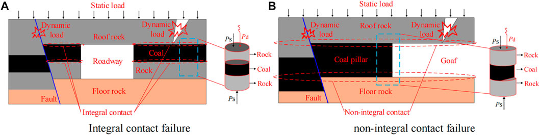
FIGURE 1. Failure mode of coal-rock composite structure. (A) Integral contact failure; (B) Non-integral contact failure.
In this paper, based on the engineering background of a reasonable coal pillar size of roadway protection in 730 track-concentrated roadways in the mining process of 7302 working face of Xinhe Coal Mine under static and dynamic loads, designing RCF is similar to coal-rock composite specimen models with non-integral contact of coal and rock, that is, “rock-coal-rock” composite specimens with different coal radial sizes. The mechanical characteristics of the specimens under static-dynamic coupling loadings are explored through SHPB test, which provides a basis for the design of the coal pillar size, and finally determines the reasonable coal pillar size combined with FLAC3D numerical simulation. This research innovates the laboratory research method of coal pillar size determination in RCF, and comprehensively considers the contact form of coal and rock and the coupling effect of dynamic and static loads. The results can provide reference for roadway protection coal pillar design under the coupling effect of dynamic and static loads in deep mines.
Background
Xinhe Coal Mine is located in the southwest edge of Jining Coalfield in Shandong Province, China. 7302 working face is located in the south of 730 track concentration roadway. The strike length of the working face is 301–340 m, and the inclined width is 110 m (excluding two gateways). The working face is arranged with two gateways, with the transportation tunnel on the west side and the return airway on the east side. As shown in Figure 2, No. 3 coal seam is mainly mined in the working face with an average buried depth of 1125.2 m and an average coal thickness of 9.51 m. The immediate roof is mudstone, the main roof is the interbedding of fine and siltstone, and the immediate bottom is mudstone.
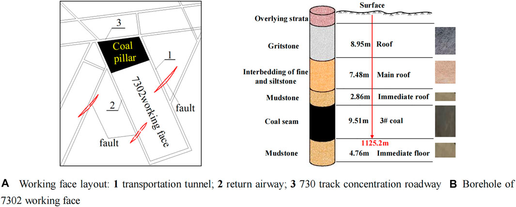
FIGURE 2. Overview of working face. (A) Working face layout; (B) Borehole of 7302 working face.
Xinhe Coal Mine has identified the coal-rock bursting liability of No. 3 coal seam and its roof and floor in 7302 working face. The results show that the bursting liability of No. 3 coal seam is strong, and the roof and floor strata is weak. All of them have a certain bursting liability, which provides material source conditions for the occurrence of dynamic disasters. The support pressure acting on the coal pillar after mining is directly proportional to the mining depth. The greater the mining depth of the coal seam, the greater the overlying strata pressure that the coal pillar bears (Das et al., 2019; Frith and Reed, 2019). The large buried depth of 7302 working face leads to high static load acting on a coal pillar for a long time. The main roof composed of interbedding of fine and siltstone constitutes the sub-key layer of the whole overlying strata, and the thick and hard gritstone above the main roof constitutes the main key layer of the whole overlying strata, which plays a decisive role in the movement characteristics of the overlying strata and the stability of the working face and the coal pillar. Mudstone and fine and siltstone above the coal seam are easy to collapse, but the collapsed gangue is not enough to fill the goaf, while the gritstone above the main roof is difficult to collapse to form cantilever rock beams. After the mining of the working face is completed, the supporting structure is formed on the coal pillar in front of the working face and the coal body behind the open-off cut. The rock beam is first pulled to the upper surface of the two supporting points, and then the lower surface in the middle part of the rock beam is pulled and fractured. In the process of tensile fracture, the elastic energy accumulated by the rock beam is released suddenly, and the dynamic load is formed, which causes dynamic disturbance to the coal pillar. In addition, there are many faults around 7302 working face. The tectonic stress of the fault and the advanced abutment pressure of the working face superimpose to form high static load, and the fault activation produces dynamic load impact to disturb the coal pillar. According to the above analysis, the coal pillar is subjected to long-term high static load, and is easily disturbed by dynamic load impact, so it is of vital importance to design a reasonable coal pillar size to ensure safe production.
Experimental Procedures and Results
RCF instability under static-dynamic coupling loadings in deep mines has the characteristics of rapid fracture of coal and rock. The SHPB experiment can realize instantaneous failure of coal and rock mass under high strain rate impact loading in the laboratory, and can restore and simulate the rapid fracture process of coal and rock mass in deep mining to the greatest extent, to realize the test of parameters such as impact dynamic strength, energy dissipation, impact loading waveform, strain rate effect, and stress wave propagation characteristics of coal and rock mass under a deep complex mining environment. It is the most important and reliable experimental method for studying the dynamic mechanical properties of coal and rock under medium and high strain rate at present (Daryadel et al., 2016; Astepe et al., 2020).
Experimental Procedures
Sample Preparation
In order to obtain the instability characteristics of a coal pillar for roadway protection in 7302 working face under static-dynamic coupling loadings by similar simulation test and determine the reasonable coal pillar size, RCF similar models (i.e., “rock-coal-rock” combined specimens with different radial sizes of coal sections) are designed for an SHPB experiment. According to SHPB test requirements (Haque et al., 2019) and test conditions, the designed specimen diameters are 50 mm, and the inclined length of 7302 working face is 110 m (excluding two gateways), that is, the inclined length of a coal pillar for roadway protection is 110 m. Then, as shown in Figure 3, the test similarity ratio is 50 mm:110 m = 1:2200.
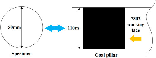
FIGURE 3. Test similarity ratio.
Coal and rock samples used in this test are collected from No. 3 coal seam and its roof and floor in No. 7302 working face of Xinhe Coal Mine. From a comprehensive histogram, it can be seen that the roof and floor of No.3 coal seam are mudstone. As shown in Figure 4, considering the height limit of the test specimen and the test effect, the roof rock sections, coal pillar sections, and floor rock sections are all 30 mm in height and 50 mm in diameter. In addition, the initial diameter of coal sections is 50 mm. At the same time, in order to simulate the change of coal pillar size during the excavation of 7302 working face, the coal sections are cut along the unilateral axial direction based on the diameter line of coal sections, and the cutting sizes are 5, 10, 15, and 20 mm, respectively. Finally, five kinds of composite specimens, model 50, model 45, model 40, model 35, and model 30, are designed. According to the radial sizes of coal sections, the sizes of coal pillar are characterized as 110, 99, 88, 77, and 66 m, respectively. Test specimens are shown in Figure 4F.
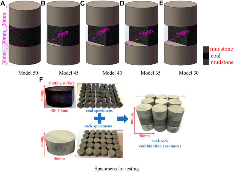
FIGURE 4. (A–E) Specimen models; (F) Specimens for testing.
Experimental Equipment and Methods
SHPB can carry out multi-field coupling coal and rock dynamic compression and deformation and failure simulation research, which is mainly composed of striker, input bar, and output bar, and the tested sample is sandwiched between the input and the output bar (Xie et al., 2019). In the SHPB system used in this test, the incidence rod, transmission rod, and absorption rod adopt a Φ50-mm steel rod with elastic modulus of 206 GPa, the compression rod material is 48CrMoA, the length of the entrance rod and the transmission rod is 3000 mm, and the length of absorption rod is 1500 mm. The cylindrical striker is 50 mm in diameter, the longitudinal wave velocity is 5122 m/s. The striker can generate half sine waves to ensure constant strain rate loading. The real-time signals are collected by the ultra-dynamic strain gauge and the strain gauges on the input and output bars. The SHPB used is equipped with Phantom M310 high-speed digital camera ultra-high-speed image synchronous acquisition system, with the highest shooting rate of 65,000 frames/sec, which can effectively capture the crack propagation and dynamic failure process.
SHPB test is based on two basic assumptions: one-dimensional stress wave hypothesis and stress uniformity hypothesis. One-dimensional stress wave hypothesis considers that every cross-section of an elastic bar always keeps in a plane state during the propagation of stress wave in a slender bar. The hypothesis of stress uniformity holds that stress wave propagates repeatedly in the specimen for several times, and the stress in the specimen is equal everywhere, so there are (Dai et al., 2010):
Therefore, the strain rate, strain, and stress of the specimens can be calculated according to the following formula (Dai et al., 2010):
Where εi, εr, and εt represent the incident, transmitted, and reflected waves, respectively; C0 is the stress wave velocity in the bar; L and A are the length and cross-sectional area of the specimens, respectively; E0 and A0 are the elastic modulus and cross-sectional area of the pressure bar, respectively.
Experimental Plans
The uniaxial compressive strength of the standard specimens of No. 3 coal seam in 7302 working face of Xinhe Coal Mine is about 19 MPa. In this test, the diameters of coal sections except model 50 are less than 50 mm, and the uniaxial compressive strength of coal sections is less than 19 MPa. Under static-dynamic coupling loadings, when the static load is within 70% of the uniaxial compressive strength, the combined loading strength of the specimens is larger than that of pure static load or pure dynamic load (Zhou et al., 2008; Wang S. et al., 2020). Therefore, in this test, the pre-static loads are controlled within 40% of the uniaxial compressive strength of the standard specimens of No. 3 coal seam, that is, the application range of the pre-static loads is determined to be 0–8 MPa. The models 30 with the smallest coal section sizes will be completely broken when the strike velocity is 3.7 m/s without pre-static loads. Considering the strong destructive ability of the test specimens by the static-dynamic coupling loadings, the strike velocity is controlled between 3.3 and 5.3 m/s.
There are 60 groups of tests. When studying the influence of dynamic loads on the failure mode of specimens, the static loads are controlled to be constant and the dynamic loads are set to four gradients. It is divided into two groups: no pre-static load and 8 MPa pre-static load. When studying the influence of static loads on the failure mode of specimens, static load is set with four gradients while the maximum impact velocity is controlled to be constant. These loads are applied as shown in Table 1.
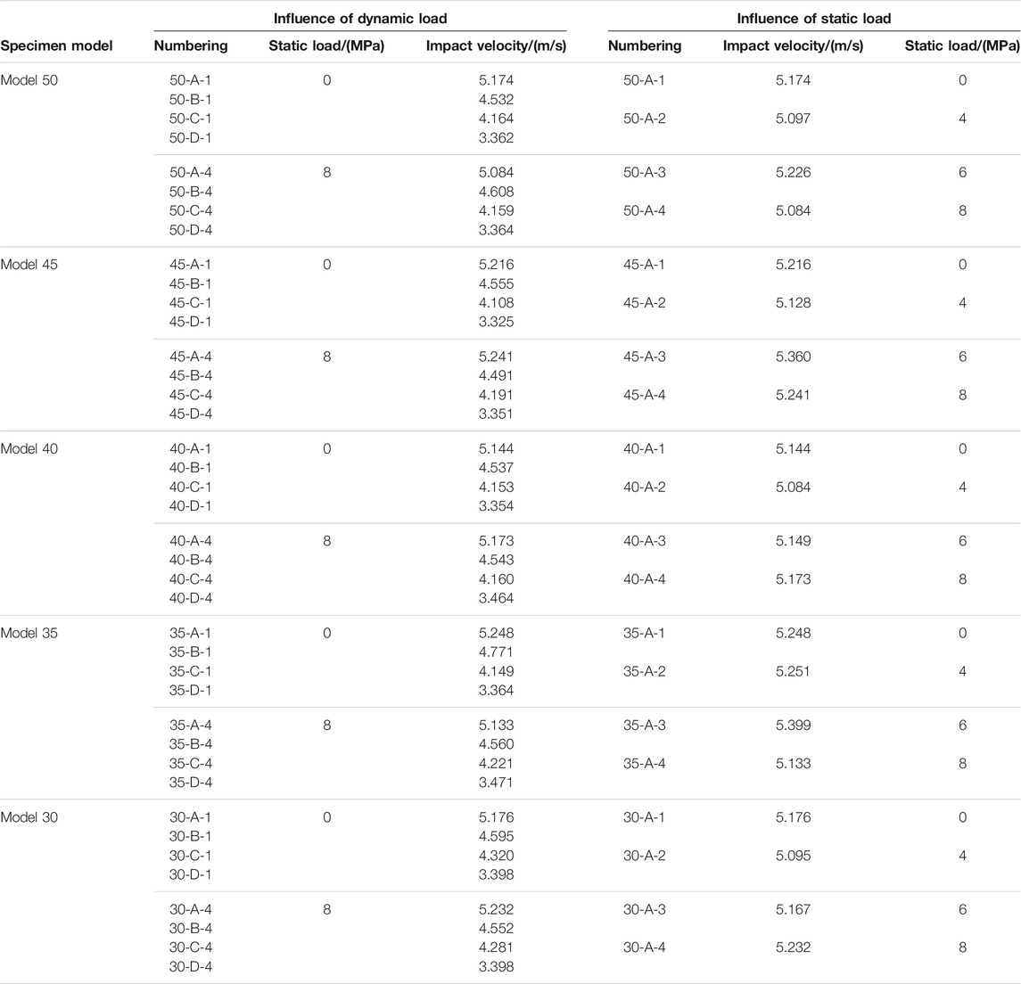
TABLE 1. Loads impose ways.
Failure Characteristics of Specimens and Discussion
Influence of Dynamic Loads
The failure processes of the specimens are photographed by a high-speed camera, and the final failure patterns of the specimens under different dynamic loads without pre-static loads are shown in Figure 5. The coal sections of models 50 have complete structures, and there is no obvious macroscopic damage under different dynamic loads. When the strike velocities are high, the models 45 have cracks or fine breakage at the edge of the longitudinal cutting faces of the coal sections. With the decrease of strike velocities, macroscopic damage no longer occurs. Models 40 have obvious cracks in the coal sections, but with the decrease of strike velocities, the number of cracks and the damage are gradually reduced. There are no obvious cracks in the specimen under the minimum strike velocity. The dynamic failure characteristics of models 35 are obvious. The coal sections present “explosive” crushing at the edges of the cutting faces, and fragments are ejected outward instantly. With the decrease of strike velocities, the damage range of coal sections gradually decreases, the fragments increase, and the ejection range decreases gradually. Compared with models 35, models 30 have changed from partial crushing of coal sections to whole crushing of coal sections, and the breakages of coal sections are intensified. The particles formed by the explosion burst outward. The crushing of coal sections in models 35 and models 30 leads to the overall instability of the specimens and the complete loss of bearing capacity.
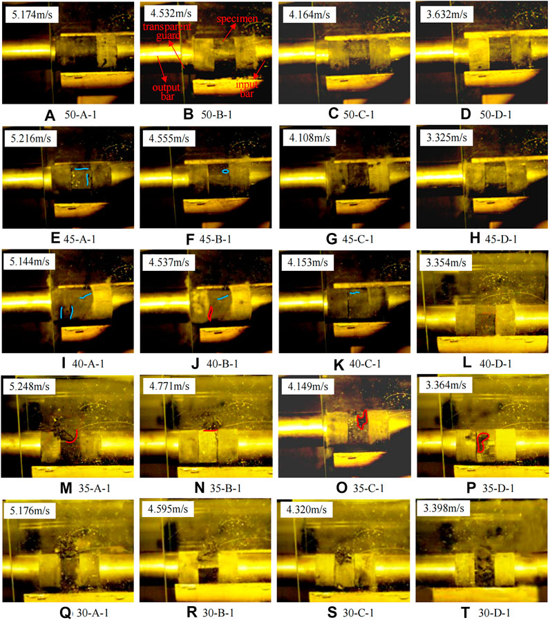
FIGURE 5. (A–T) Failure patterns of specimens under different dynamic loads without pre-static load (In the figure, the blue line indicates the position of the crack after the failure of the specimen, and the red line represents the boundary of the spalling area of the specimen. The blue and red lines in Figures 10–12 also indicate this meaning).
The final failure patterns of specimens under different dynamic loads with 8 MPa pre-static load are shown in Figure 6. Consistent with the failure law of each specimen without pre-static load, models 50 have complete overall structures with no obvious cracks or breakage. Models 45 and models 40 have slight cracks or breakage on the coal sections. Nevertheless, models 45 and models 40 are good in integrity and bearing capacity. However, rock burst is obvious in the laboratory of models 35 and models 30, with coal sections bursting and breaking outward, and the damage of models 30 is more serious.
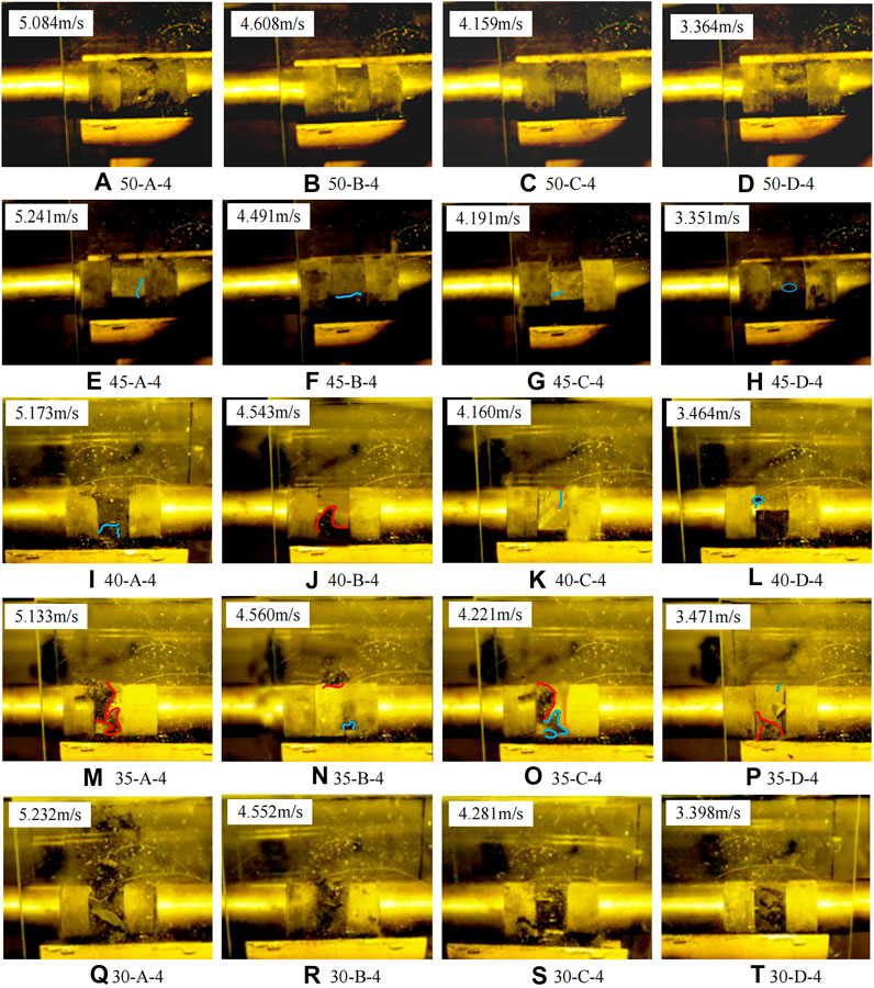
FIGURE 6. (A–T) Failure patterns of specimens under different dynamic loads with 8 MPa pre-static load.
Under the two loading modes, the failure of the specimens mainly occurred in the coal sections. With the decrease of the section size of coal, the failure becomes serious. Models 50, models 45, and models 40 only show slight cracks or breakage at the cutting edge of the coal sections, but the integrity and bearing capacity of the specimens are good. While models 35 and models 30 are severely broken and the coal sections are unstable, so the whole specimens are no longer stable. On the other hand, the dynamic loads have obvious influence on the failure of specimens, and the failure of the same models increases with the increase of strike velocities under the same pre-static load. In addition, most of the specimens are obviously damaged at the edge of the longitudinal cutting face of the coal sections, which is consistent with the serious damage of the underground coal pillar at the coal wall. The change of the stress state reduces its edge binding force, so the damage increases.
Influence of Static Loads
In samples, the final damage patterns under different pre-static loads at maximum strike velocity are shown in Figure 7. Macroscopically, there are no obvious damages in models 50. Models 45 are slightly broken at the edges of longitudinal cutting faces of coal sections. Compared with models 50 and models 45, the damage of models 40 is intensified, but the integrity of models 40 is good. With the increase of pre-static load, the damage of samples gradually decreases. Models 35 have been damaged obviously, and the breakage not only appeared at the edge of cutting faces, but extended to most of the coal sections. In the range of 0–6 MPa, with the increase of pre-static loads, the “explosive” crushing of coal sections reduced gradually, but when 8 MPa pre-static load is applied, the “explosive” crushing aggravated obviously, and the crushing range is more than two-thirds of the coal section, as well as the crushing particle sizes are small. Models 30 show the whole “explosive” damage of coal sections. In samples of models 30, when 4 MPa pre-static load is applied, the damage of the coal section is lightest. But when 8 MPa pre-static load is applied, the fracture of the sample is the most serious, at this time, the rock section at the coal-rock interface on the input bar side is also broken slightly.
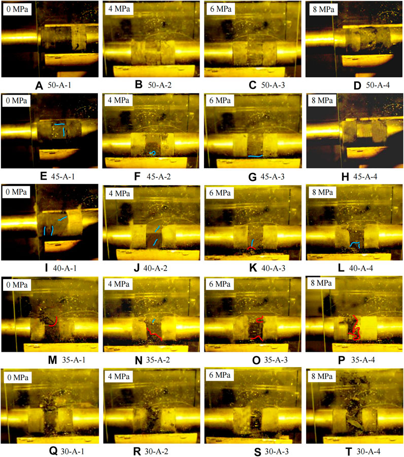
FIGURE 7. (A–T) Failure patterns of specimens under different pre-static loads at the maximum strike velocity.
Under constant dynamic load, damage of the samples still mainly occurs in coal sections under different static loads, and the damage is closely related to the size of the coal section. There is no damage in models 50, models 45, and models 40, which have good bearing capacity. The smaller models 35 and models 30 have “explosive” crushing in the coal sections, and the samples no longer have bearing capacity. Pre-static loads have an obvious influence on sample damage. The damage of models 50, models 45, and models 40 decreases gradually with the increase of pre-static loads under the same dynamic load. Under the same dynamic load, the damage of models 35 decreases gradually with the increase of pre-static loads from 0 to 6 MPa, and further increases when the pre-static load increases to 8 MPa. In the range of 0–4 MPa, with the increase of pre-static loads, the damage of the models 30 decreases gradually, and in the range of 6–8 MPa, the damage of the samples aggravates further. Combined with the failure characteristics of models 35 and models 30, it is judged that there is a critical value of pre-static load. That is, within the critical value range, the damage of the samples is negatively correlated with the pre-static loads, and when exceeding the critical value, the damage of the samples is positively correlated with the pre-static loads.
Strength Characteristics of Specimens and Discussion
Influence of Dynamic Loads
The dynamic strength evolution curves of specimens under different dynamic loads without pre-static load are shown in Figure 8, and those under different dynamic loads with 8 MPa pre-static load are shown in Figure 9.
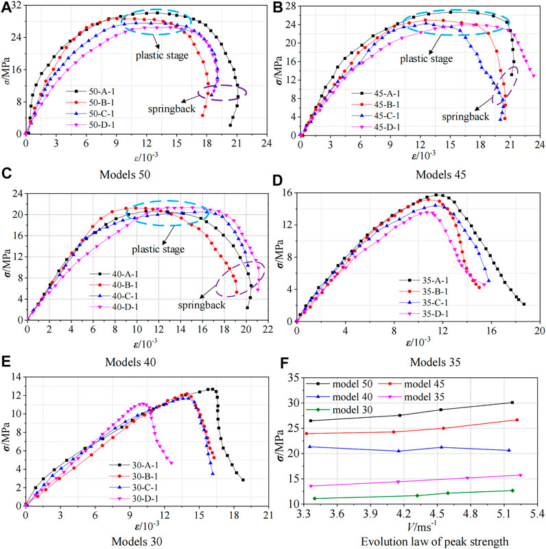
FIGURE 8. (A–E) Strength evolution of specimens under different dynamic loads without pre-static load; (F) Evolution law of peak strength of each model.
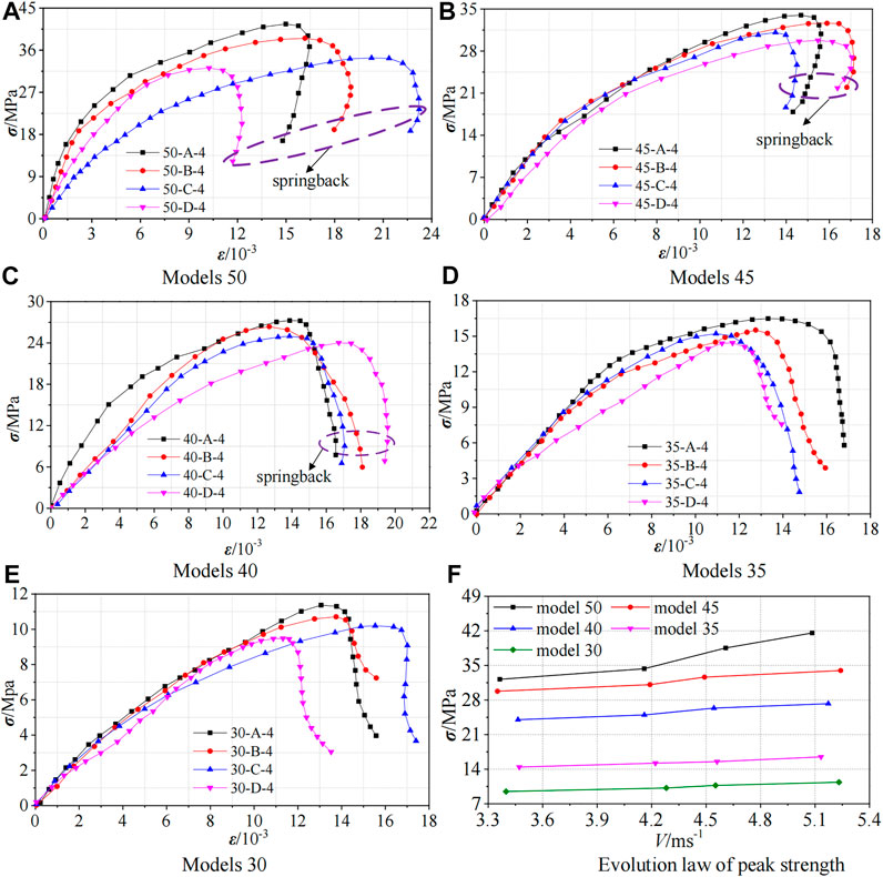
FIGURE 9. (A–E) Strength evolution of specimens under different dynamic loads with 8 MPa pre-static load; (F) Evolution law of peak strength of each model.
The dynamic strength evolution law of specimens under different strike velocities is basically the same when no pre-static load is applied and when 8 MPa pre-static load is applied. After the peak strength, the models show great differences. The stress-strain curves of models 50 and models 45 show obvious spring back, and the stress-strain curves of models 40 also show slight spring back. This is because the coal sections of models 50, models 45, and models 40 are relatively complete, and the elastic energy stored inside the specimens is greater than the kinetic energy applied. The specimens still have bearing capacity after reaching the strength limit in the process of elastic deformation. With the gradual release of the internal elastic energy, the deformation of the specimens springs back slightly and the strain decreases accordingly. The coal sections of models 35 and models 30 are small in size, and the kinetic energy exerted by the outside is greater than the elastic energy stored inside the specimens. After reaching the peak strength, the specimens will continue to absorb the strike kinetic energy, and the residual strength of the specimens will continue to decrease. The specimens are damaged seriously, and the deformation continues to increase, as does the strain. Hence, there is no spring back in the stress-strain curve. Different from 8 MPa pre-static load, there are obvious plastic stages in the stress-strain curves of models 50, models 45, and models 40 without pre-static load. This is because the application of pre-static loads inhibits the crack expansion of coal and rock, and the small stress increase will not cause the rapid growth of strain, while the crack expansion will not be inhibited without pre-static load. Under dynamic loads, the fracture rate and volume expansion rate of the specimens are accelerated, and the strain increases rapidly with the increase of stress, so there are plastic stages in the stress-strain curves without pre-static load. There is no obvious plastic stage in the stress-strain curves of models 35 and models 30 regardless of whether pre-static load is applied. This is because the strength of these two models is low, and they will be destroyed instantly under dynamic loads. Therefore, there is no plastic stage.
It can be seen from Figure 8F and Figure 9F that the greater the strike velocities are, the higher the dynamic strength of the specimens is, indicating that the specimens have a stronger ability to resist damage. In addition, there is a strong correlation between the dynamic strength of the specimens and the sizes of the coal sections. The larger the sizes of the coal sections are, the higher the dynamic strength of the specimens is. The strength reduction ratio of the other four models is calculated based on the strength of models 50. When no pre-static load is applied, the maximum reduction of strength of models 45 is 12.84%, that of models 40 is 19.44–31.44%, and that of models 35 and models 30 is 47.09–48.74% and 57.55–58.10%, respectively. When 8 Mpa pre-static load is applied, the strength of models 45 and models 40 are reduced by 19 and 35%, respectively, compared to those of models 50. The maximum reduction of models 35 and models 30 is 60.34 and 72.68%, respectively. The strength of models 50 is the highest, and the strength of models 45 and models 40 is slightly lower than that of models 50, while the strength of models 35 and models 30 is greatly reduced. The dynamic strength of the specimens is very low, and they can no longer resist external damage.
Influence of Static Loads
The dynamic strength evolution curves under different pre-static loads at maximum strike velocity are shown in Figure 10. The evolution law of curves is similar to that of curves under different dynamic loads. The integrity of coal sections is good in models 50, models 45, and models 40, and their elastic properties which are larger than the external kinetic energy can be stored internally. When the elastic properties are released, the deformation of the specimens recovers slightly, the strain decreases, and the curves spring back after the peak strength. The integrity of models 35 and models 30 coal sections is poor, and the elastic property stored inside is less than the external kinetic energy, the stress-strain curves continue to deform and destroy greatly after the peak strength. Therefore, the strain increases continuously.
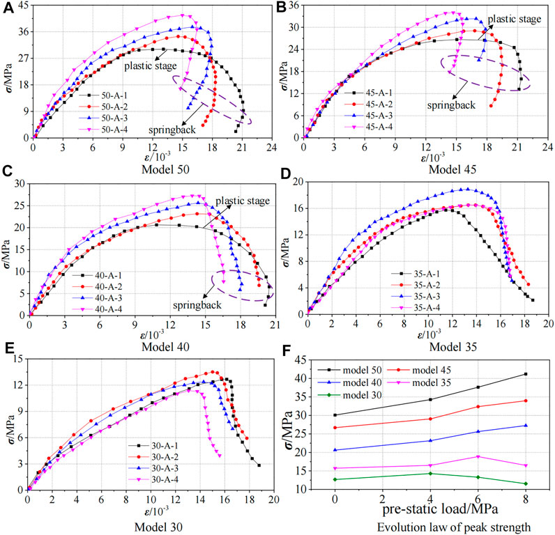
FIGURE 10. (A–E) Strength evolution of specimens under different static loads at maximum strike velocity; (F) Evolution law of peak strength of each model.
It can be seen from Figure 10F that the strength of models 50, models 45, and models 40 increases with the increase of pre-static loads, which is because the pre-static loads inhibit the development of original cracks and the generation of new cracks, thereby promoting the cracks closure and improving the dynamic strength of the specimens. The strength of models 35 increases with the increase of pre-static loads from 0 to 6 MPa, but decreases when 8 MPa pre-static load is applied. In the range of 4 MPa pre-static loads, the strength of models 30 increases with the increase of pre-static load, while the strength decreases when 6 and 8 MPa pre-static loads are applied, and the higher the pre-static load is, the lower the strength is. Generally speaking, there is a critical value for the increasing effect of pre-static load on the dynamic strength of the specimens. When it is less than the critical value, the pre-static loads can strengthen the dynamic strength of the specimen. On the other hand, when it exceeds this critical value, the pre-static loads will cause original damage to the specimens, which will not only promote the penetration of the original cracks of the specimens, but also produce new cracks to further increase the number of cracks in the specimens. At this time, even a small external dynamic disturbance will cause serious deformation and failure of the specimens, which also explains the reason why the coal pillar is easily disturbed by dynamic load under high static load in deep mines. The pre-static loads applied in this test do not reach the critical values of models 50, models 45, and models 40, but models 35 and models 30 do. In addition, the influence of section size of coal on the dynamic strength of the specimens is still significant, and the dynamic strength decreases with the decrease of section size of coal.
Based on the strength of models 50, the strength reduction ratios of the other four models are calculated. Compared with models 50, the dynamic strength of models 45 decreases by 10.73–17.53%, the strength of models 40 decreases by 20.50–33.82%, and the maximum strength decreases of models 35 and models 30 are 59.97 and 71.98%, respectively. The strength of models 50 is the highest, although the strength of models 45 and models 40 is slightly lower than that of models 50, but their strength is still higher, while that of models 35 and models 30 decreases greatly, their dynamic strength is low, and their ability to resist external damage is weak.
Determination of Coal Pillar Size
Through the analysis of the failure characteristics and dynamic strength characteristics of the specimens, it can be concluded that models 50, models 45, and models 40 are damaged slightly. The ability of them to resist external damage is strong with high dynamic strength. Models 35 and models 30 are seriously damaged, the strength is low, and the ability to resist damage is weak, so that the stability is poor. Therefore, it is determined that the stability requirements of the specimens can be met when the section size of coal is larger than 40 mm. Considering the economic and safety benefits, the 40 mm coal section size is selected as the best size. Combined with the similarity ratio, the coal pillar size of 730 track concentrated roadway in the mining process of 7302 working face is 88 m.
Numerical Simulation
Numerical Model
In engineering practice, coal and rock mass are buried deep in the ground, and their loads in the process of impact or vibration are complex. Similar simulation tests cannot fully reflect the coal and rock failure in the process of advancing the working face. Therefore, on the basis of similar test results, with the help of FLAC3D numerical simulation software, which can comprehensively reflect the advancing condition of the working face, simulating and studying the stability of coal pillar, the stress changes of coal pillar and overburden rock during the excavation of 7302 working face under dynamic load, and finally the reasonable size of coal pillar for roadway protection is determined by inversion calculation.
Selecting the coal pillar of roadway protection in 730 track concentrated roadway in the mining process of 7302 working face as the research object, referring to the comprehensive histogram and plane position diagram of working face, the numerical model is established by FLAC3D software as shown in Figure 11. The model size is 350 m × 200 m × 91.5 m (length × width × height), and the Mohr-Coulomb model is adopted. The static-dynamic coupling loading is applied. When the static load calculation is carried out, the bottom boundary of the numerical model is fixed, the front, back, left, and right boundaries are fixed with normal displacement, and the top boundary is free. According to the multiplication of the average bulk density of overlying strata and the average thickness of overlying strata, the uniform load exerted by overlying strata on the working face in the model is about 25.5 MPa. During the dynamic load calculation, the left and right boundaries of the numerical model are free, and the normal displacement of the bottom is fixed. The dynamic stress wave is applied on the top, and the dynamic stress wave is set as half sine stress wave. According to the existing research data of Xinhe Coal Mine (Liu, 2017), the dynamic load strength is set as 50 MPa, the frequency is taken as 50 Hz, and the action time is 0.05 s. When the 120-m coal pillar is reserved, the 7302 working face shall be fully excavated at one time, and then the excavation shall be conducted for 10 m on the basis of a 120-m coal pillar until the coal pillar size is 60 m. One survey line is arranged along the strike in the middle of the roof of the working face to monitor the stress of the overlying strata of the working face and the coal pillar, and the other survey line is arranged along the strike 20 m in front of the coal wall to monitor the stress inside the coal pillar.
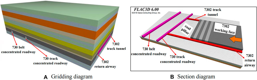
FIGURE 11. Numerical model diagram. (A) Gridding diagram; (B) Section diagram.
Simulation Results
The stress evolution curves along the strike of the working face are shown in Figure 12A. The evolution law of overlying strata stress along the working face under different coal pillar sizes is basically the same. After the mining of the working face is completed, the overlying strata stress in the goaf is released, and its value decreases to close to 0 with the increase of time and basically does not change. The overlying strata in the goaf tend to be stable and become a decompression zone. Affected by the advance abutment pressure of the working face, the coal pillar position becomes the pressure increasing area, and the overlying strata stress at the coal pillar position rises sharply. The stress of the overlying strata on the side of the goaf increases obviously and reaches the peak value in the range of 8–13 m in front of the working face. The stress of overlying strata decreases with the distance from the goaf.
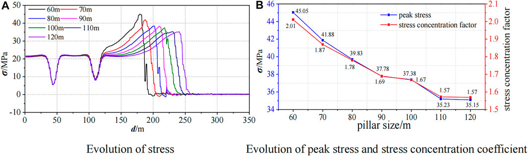
FIGURE 12. Stress evolution curve of overlying strata. (A) Evolution of stress; (B) Evolution of peak stress and stress concentration coefficient.
The degree of stress concentration can usually be expressed by stress concentration coefficient. Take the stress peak values and calculate the stress concentration factors to draw the evolution curves as shown in Figure 12B. The peak stress decreases linearly in the range of 60–80 m coal pillar, and the decreasing trend is obvious. The peak stress of overlying strata at 60 m coal pillar is far greater than that of other coal pillars, and its value is 45.05 MPa. The initial rock stress obtained by simulation is 22.4 MPa, so the stress concentration factor is 2.01. The peak stresses of 70 and 80 m coal pillars are 41.88 and 39.83 MPa, respectively, and the stress concentration factors are 1.87 and 1.78, respectively. Compared with 60-m coal pillars, their peak stresses are reduced by 7.04 and 11.59%, respectively. At 90 and 100 m coal pillars, the peak stresses are 37.78 and 37.38 MPa, respectively, and the stress concentration factors are 1.69 and 1.67, respectively, which are close to each other and the stress tends to be stable. When the coal pillar sizes are more than 100 m, the peak stresses decrease slowly. The peak stresses of overlying strata of 110 and 120 m coal pillars are 35.23 and 35.15 MPa, which are basically the same. Compared with a 90-m coal pillar, the peak stresses of overlying strata are reduced by 6.74 and 6.96%, respectively, and 5.75 and 5.97%, respectively, compared to that of a 100-m coal pillar. The results show that the stresses of overlying strata changes in a small range when the coal pillar sizes are greater than 90 m, and the influence of the coal pillar size on stress is no longer significant.
According to the stress evolution law of a coal pillar overlying strata under the coupling action of static and dynamic loads with different coal pillar sizes, when the coal pillar size is greater than 90 m, the stress of the coal pillar overlying strata begins to decrease and tends to moderate and homogenize. Therefore, the numerical simulation determined that the pillar size of roadway protection in 730 track concentrated roadway in the mining process of 7302 working face in Xinhe Coal Mine was 90 m.
Determination of Coal Pillar Size
According to the results of an SHPB similar simulation test, the coal pillar size of 730 track concentrated roadway in the mining process of 7302 working face is 88 m, and the coal pillar size calculated by FLAC3D numerical simulation software is 90 m. The difference between the test results and the numerical simulation results is 2 m. The two values are basically consistent, which proves the reliability of the research results. Considering safety benefits, the coal pillar size of 730 track concentrated roadway in the mining process of 7302 working face is 90 m.
Engineering Application and Effect
Monitoring Scheme
The closest distance to the final mining position of the 7302 working face is 730 track concentrated roadway. In order to verify the rationality of the coal pillar size of the roadway protection, three observation stations are arranged in 730 track concentrated roadway for monitoring. Station 1 is arranged near the 7302 track tunnel side, station 2 is arranged right in front of the middle of the coal pillar, and station 3 is arranged near the 7302 return airway side. As shown in Figure 13, the observation begins when the coal pillar size is 150 m, and the observation stations are arranged on the side of 730 track concentrated roadway near the coal pillar. The monitoring contents include the stress evolution in the coal pillar and the roof separation of 730 track roadway. The stress monitoring is drilled in the coal pillar, and each station is arranged with one deep borehole and one shallow borehole (14 and 8 m). The distance between them is 0.5 m, and a borehole stress gauge is placed at the bottom of each borehole. The mechanical roof separation indicators are used for roof separation monitoring. The deep base points are set at 6 m, which are arranged in the main roof, and the shallow base points are set at 3 m, which are arranged in the immediate roof.

FIGURE 13. Schematic diagram of station layout.
Monitoring Results
As shown in Figure 14, in station 1, the stress of a 14-m borehole increases almost linearly in the range of coal pillar sizes from 150 to 120 m, and then increases greatly. Finally, the stress tends to be flat in the range of 110–90 m, and the stress of a 90-m coal pillar is 9.76 MPa. The stress of an 8-m borehole increases rapidly in the range of coal pillar size from 150 to 110 m, and then changes smoothly. The stress of a borehole is 7.62 MPa when the coal pillar is 90 m. In station 2, the stress of a 14-m borehole changes little when the coal pillar sizes are 150 and 140 m, and then increases in the form of approximate quadratic function. When the coal pillar sizes are less than 110 m, the stress only increases slightly. When the coal pillar size is 90 m, the stress is 9.47 MPa. The stress of an 8-m borehole shows an increasing trend of quadratic function in the range of coal pillar sizes from 150 to 100 m. The stress is basically equal when the coal pillar sizes are 90 and 100 , and the stress of a 90 = m coal pillar is 7.34 MPa. In station 3, the stress change trend of a 14-m borehole is basically consistent with that of an 8-m borehole, and the stresses of 100-m and 90-m coal pillars are similar, the stress of a 14-m borehole is 10.78 MPa and that of an 8-m borehole is 8.25 MPa under a 90-m coal pillar.
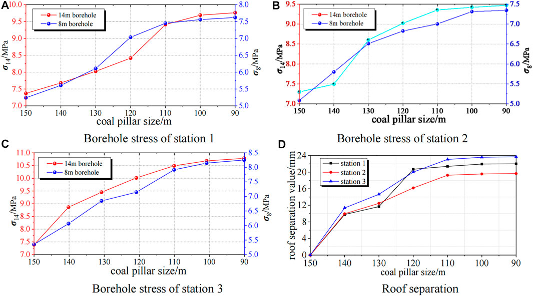
FIGURE 14. Monitoring results. (A) Borehole stress monitored by three stations; (B) Roof separation monitored by three stations.
The roof separations of stations 2 and 3 tend to be stable when the coal pillar sizes are less than 110 m, and roof separations of station 1 tend to be stable when the coal pillar sizes are less than 120 m. Therefore, it is inferred that roof separations of stations 1, 2, and 3 tend to be stable when the coal pillar sizes are less than 110 m in different positions of 730 track concentrated roadway, and the roof separations of stations 1, 2, and 3 are 22.01, 19.66, and 23.70 mm, respectively, when the coal pillar is 90 m.
The stresses and roof separations of boreholes at different depths tend to be stable when the coal pillar sizes are less than 110 m. That is, when the coal pillar sizes are 110, 100, and 90 m, respectively, the measured stresses are basically the same, as are the roof separations. The stress value is less than the warning value, and the roof separation is less than 30 mm when the coal pillar is 90 m, which is within the controllable range. Therefore, the 90-m coal pillar can fully ensure the stability of the coal pillar and 730 track concentrated roadway, and fully meet the needs of safety production.
Conclusions
In this study, “rock—coal—rock” composite specimens which can accurately simulate the non-integral contact of RCF coal and rock are designed and the coupling effect of static and dynamic loads is fully considered. The mechanical properties of composite specimens are studied by SHPB test, which provides a basis for setting the size of a coal pillar in RCF, and the reasonable size of a coal pillar for roadway protection is determined by numerical simulation. Compared with current published works, this paper highlights three important messages:
1) According to the characteristic of non-integral contact between coal and rock in RFC, the combination form of coal-rock combination specimen is innovated, and the influence of the change of radial size of coal section on the failure law and strength characteristics of “rock—coal—rock” specimen is studied, and the size of the coal pillar is simulated by the radial size of the coal section.
2) Considering the coupling effect of dynamic and static loads in deep mining, the influence of multi-gradient dynamic and static loads on the mechanical properties of coal and rock is studied.
3) Combining the SHPB similarity test with numerical simulation calculation, a new method for more reliable and comprehensive determination of coal pillar size for roadway protection is put forward.
The results show that the failure of the composite specimens mainly occurs in the coal sections, and the larger the radial sizes of the coal sections, the lighter the failure is and the higher the dynamic strength is. Models 50, models 45, and models 40 have good stability, while models 35 and models 30 have low strength and poor resistance to external damage. The dynamic loads can enhance the dynamic strength of the specimens, while the static loads have a critical value of damage. Within the critical value range, increasing the static loads can restrain the failure of the specimens and increase the dynamic strength of the specimens. When the static loads exceed the critical value range, increasing the static loads will aggravate the failure of the specimens and reduce the dynamic strength of the specimens. In addition, the stress-strain curves of models 50, models 45, and models 40 have a plastic stage when only dynamic load is applied, but other cases do not exist. According to the SHPB similarity test, the coal section size of models 40 is the best coal size, the coal pillar size calculated by similarity is 88 m, and the coal pillar size calculated by numerical simulation is 90 m, which is very consistent with each other. Based on the safety benefits, the coal pillar size of 730 track concentrated roadway in the mining process of 7302 working face in Xinhe Coal Mine is finally determined to be 90 m. In order to verify the rationality of the designed pillar size of roadway protection, monitor the stress changes in the pillar of 730 track concentrated roadway closest to the end mining position of 7302 working face and the roof separation of 730 track concentrated roadway. The monitoring results show that the designed dimension of a 90-m pillar can ensure the stability of the pillar and the surrounding rock of 730 track concentrated roadway, and meet the needs of safe mining in 7302 working face.
Data Availability Statement
The original contributions presented in the study are included in the article/Supplementary Material, further inquiries can be directed to the corresponding authors.
Author Contributions
QL, JL, and ZW proposed the idea. JL contributed to writing the manuscript. KL and CZ contributed to the numerical simulation. KL and CZ contributed to analyzing the data. All authors contributed to the article and approved the submitted version.
Funding
This study was sponsored by Key Projects of Natural Science Foundation of Shandong Province (grant numbers ZR2020KE030), China Postdoctoral Science Foundation (No.2020M672135), and the Science and Technology Program of Shandong Colleges and Universities (grant numbers J18KA185).
Conflict of Interest
The authors declare that the research was conducted in the absence of any commercial or financial relationships that could be construed as a potential conflict of interest.
Publisher’s Note
All claims expressed in this article are solely those of the authors and do not necessarily represent those of their affiliated organizations, or those of the publisher, the editors and the reviewers. Any product that may be evaluated in this article, or claim that may be made by its manufacturer, is not guaranteed or endorsed by the publisher.
Acknowledgments
The field information from the study site was provided by the Xinhe Coal Mine. The authors are grateful for the support.
References
Astepe, B. S., Aytuluk, H. G., Yavuz, A., Türkay, Ü., Terzi, H., and Kale, A. (2020). Intraoperative Superior Hypogastric Plexus Block During Cesarean Section: A New Technique for Pain Relief. J. Matern. Fetal Neonatal. Med. 33 (15), 2657–2663. doi:10.1080/14767058.2019.1676414
Beijing, X., Ai, D., and Yang, Y. (2019). Crack Detection and Evolution Law for Rock Mass Under SHPB Impact Tests. Shock Vib. 2019, 1–12. doi:10.1155/2019/3956749
Chen, S. J., Yin, D. W., Jiang, N., Wang, F., and Guo, W. J. (2019). Simulation Study on Effects of Loading Rate on Uniaxial Compression Failure of Composite Rock-Coal Layer. Geomech. Eng. 17 (4), 333–342. doi:10.12989/gae.2019.17.4.333
Dai, F., Huang, S., Xia, K., and Tan, Z. (2010). Some Fundamental Issues in Dynamic Compression and Tension Tests of Rocks Using Split Hopkinson Pressure Bar. Rock Mech. Rock Eng. 43 (6), 657–666. doi:10.1007/s00603-010-0091-8
Damghani, M., Rahmannejad, R., and Najafi, M. (2019). Evaluation of the Effect of Coal Seam Dip on Stress Distribution and Displacement Around the Mechanized Longwall Panel. J. Min. Sci. 55 (5), 733–742. doi:10.1134/S1062739119056100
Daryadel, S. S., Mantena, P. R., Kim, K., Stoddard, D., and Rajendran, A. M. (2016). Dynamic Response of Glass Under Low-Velocity Impact and High Strain-Rate SHPB Compression Loading. J. Non Cryst. Sol. 432, 432–439. doi:10.1016/j.jnoncrysol.2015.10.043
Das, A. J., Mandal, P. K., Paul, P. S., and Sinha, R. K. (2019). Generalised Analytical Models for the Strength of the Inclined as Well as the Flat Coal Pillars Using Rock Mass Failure Criterion. Rock Mech. Rock Eng. 52 (10), 3921–3946. doi:10.1007/s00603-019-01788-7
Frith, R., and Reed, G. (2019). Limitations and Potential Design Risks When Applying Empirically Derived Coal Pillar Strength Equations to Real-Life Mine Stability Problems. Int. J. Mining Sci. Techn. 29 (1), 17–25. doi:10.1016/j.ijmst.2018.11.024
Fu, B., Zou, Z. H., Wang, Y. X., Liu, S., and Xiao, Y. C. (2016). Numerical Simulation of Different Combination of Coal and Rock Sample Mechanics and Acoustic Emission Characteristics. J. Nanjing Univ. Sci. Techn. 40 (04), 485–492. doi:10.14177/j.cnki.32-1397n.2016.40.04.018
Guo, C., Jiang, F., Liu, R., and Yang, Y. (2011). Size Effect on the Contact State Between Fracture Specimen and Supports in Hopkinson Bar Loaded Fracture Test. Int. J. Fract. 169 (1), 77–84. doi:10.1007/s10704-011-9588-8
Guo, W. Y., Tan, Y. L., Yu, F. H., Zhao, T. B., Hu, S. C., Huang, D. M., et al. (2018). Mechanical Behavior of Rock-Coal-Rock Specimens with Different Coal Thicknesses. Geomech. Eng. 15 (4), 1017–1027. doi:10.12989/gae.2018.15.4.1017
Haque, A., Ghachi, R. F., Alnahhal, W. I., Aref, A., and Shim, J. (2019). Hybrid Split Hopkinson Pressure Bar to Identify Impulse-dependent Wave Characteristics of Viscoelastic Phononic Crystals. Exp. Mech. 59 (1), 95–109. doi:10.1007/s11340-018-00441-8
Huang, B., and Liu, J. (2013). The Effect of Loading Rate on the Behavior of Samples Composed of Coal and Rock. Int. J. Rock Mech. Mining Sci. 61, 23–30. doi:10.1016/j.ijrmms.2013.02.002
Huang, B. X., Zhang, N., Jing, H. W., Kan, J. G., Meng, B., Li, N., et al. (2020). Large Deformation Theory of Rheology and Structural Instability of the Surrounding Rock in Deep Mining Roadway. J. China Coal Soc. 45 (03), 911–926. doi:10.13225/j.cnki.jccs.SJ19.1451
Kong, D. Z., Wang, Z. H., Li, X. M., Wang, Y. L., and Wang, C. (2014). Study of Reasonable Width of Full-Mechanized Top-Coal Caving with Large Mining Height. Rock Soil Mech. 35, 460–466. doi:10.16285/j.rsm.2014.s2.040
Kumar, A., Waclawik, P., Singh, R., Ram, S., and Korbel, J. (2019). Performance of a Coal Pillar at Deeper Cover: Field and Simulation Studies. Int. J. Rock Mech. Mining Sci. 113, 322–332. doi:10.1016/j.ijrmms.2018.10.006
Li, J., Qiang, X. B., Wang, W. S., and Wang, F. (2019). Distribution Law of Principal Stress Difference of Deep Surrounding Rock of Gob-Side Entry and Optimum Design of Coal Pillar Width. Teh. Vjesn. 26 (6), 1743–1752. doi:10.17559/TV-20190813163025
Li, C., Xu, Y., Chen, P., Li, H., and Lou, P. (2020). Dynamic Mechanical Properties and Fragment Fractal Characteristics of Fractured Coal-Rock-like Combined Bodies in Split Hopkinson Pressure Bar Tests. Nat. Resour. Res. 29, 3179–3195. doi:10.1007/s11053-020-09656-w
Liu, S. H., Mao, D. B., Qi, Q. X., and Li, F. M. (2014a). Under Static Loading Stress Wave Propagation Mechanism and Energy Dissipation in Compound Coal-Rock. J. China Coal Soc. 39 (S1), 15–22. doi:10.13225/j.cnki.jccs.2013.0411
Liu, J., Wang, E., Song, D., Wang, S., and Niu, Y. (2014b). Effect of Rock Strength on Failure Mode and Mechanical Behavior of Composite Samples. Arab J. Geosci. 8, 4527–4539. doi:10.1007/s12517-014-1574-9
Liu, Q., Chai, J., Chen, S., Zhang, D., Yuan, Q., and Wang, S. (2020). Monitoring and Correction of the Stress in an Anchor Bolt Based on Pulse Pre‐Pumped Brillouin Optical Time Domain Analysis. Energy Sci. Eng. 8 (6), 2011–2023. doi:10.1002/ese3.644
Liu, X. S. (2017). Study on the Mechanism and Control of Rockburst in Roadways Under Dynamic Loads. Qingdao, China: Shandong University of Science and Technology. doi:10.27275/d.cnki.gsdku.2017.000014
Najafi, M., Shishebori, A., and Gholamnejad, J. (2017). Numerical Estimation of Suitable Distance Between Two Adjacent Panels' Working Faces in Shortwall Mining. Int. J. Geomech. 17 (4), 1–11. doi:10.1061/(asce)gm.1943-5622.0000784
Pan, J. F., Qi, Q. X., Liu, S. H., Wang, S. H., Ma, W. T., and Kang, X. C. (2020). Characteristics, Types and Prevention and Control Technology of Rock Burst in Deep Coal Mining in China. J. China Coal Soc. 45 (01), 111–121. doi:10.13225/j.cnki.jccs.YG19.1638
Poulsen, B. A., Shen, B., Williams, D. J., Huddlestone-Holmes, C., Erarslan, N., and Qin, J. (2014). Strength Reduction on Saturation of Coal and Coal Measures Rocks with Implications for Coal Pillar Strength. Int. J. Rock Mech. Mining Sci. 71, 41–52. doi:10.1016/j.ijrmms.2014.06.012
Wang, K., Du, F., Zhang, X., Wang, L., and Xin, C. (2017). Mechanical Properties and Permeability Evolution in Gas-Bearing Coal-Rock Combination Body Under Triaxial Conditions. Environ. Earth Sci. 76 (24), 1–19. doi:10.1007/s12665-017-7162-z
Wang, P., Jia, H., and Zheng, P. (2020a). Sensitivity Analysis of Bursting Liability for Different Coal-Rock Combinations Based on Their Inhomogeneous Characteristics. Geomat. Nat. Hazards Risk 11 (1), 149–159. doi:10.1080/19475705.2020.1714754
Wang, S., Huang, L., and Li, X. (2020b). Analysis of Rockburst Triggered by Hard Rock Fragmentation Using a Conical Pick Under High Uniaxial Stress. Tunn. Undergr. Space Techn. 96, 103195–103215. doi:10.1016/j.tust.2019.103195
Xie, B. J., and Yan, Z. (2019). Dynamic Mechanical Constitutive Model of Combined Coal-Rock Mass Based on Overlay Model. J. China Coal Soc. 44 (02), 463–472. doi:10.13225/j.cnki.jccs.2018.1007
Zhang, Z. T., Liu, J. F., Wang, L., Yang, H. T., and Zuo, J. P. (2012). Effects of Combination Mode on Mechanical Properties and Failure Characteristics of the Coal-Rock Combinations. J. China Coal Soc. 37 (10), 1677–1681. doi:10.13225/j.cnki.jccs.2012.10.021
Zhang, W. Q., Shi, B., and Mu, C. M. (2016). Experimental Research on Failure and Energy Dissipation Law of Coal Under Impact Load. J. Mining Saf. Eng. 33 (02), 375–380. doi:10.13545/j.cnki.jmse.2016.02.029
Zhang, J. M., Li, Q. S., Zhang, Y., Cao, Z. G., and Wang, X. Z. (2019). Definition of Deep Coal Mining and Response Analysis. J. China Coal Soc. 44 (05), 1314–1325. doi:10.13225/j.cnki.jccs.2019.6018
Zhang, X., Hu, J., Xue, H., Mao, W., Gao, Y., Yang, J., et al. (2020). Innovative Approach Based on Roof Cutting by Energy-Gathering Blasting for Protecting Roadways in Coal Mines. Tunn. Undergr. Space Techn. 99, 103387–103412. doi:10.1016/j.tust.2020.103387
Keywords: damage characteristics, static-dynamic coupling loadings, coal section radial size, coal-rock composite specimen, roadway protection coal pillar
Citation: Li Q, Li J, Wang Z, Li K and Zhang C (2021) Study on Coal Pillar Size Design Based on Non-integral Contact Structure of Coal and Rock Under Static and Dynamic Loads. Front. Mater. 8:721713. doi: 10.3389/fmats.2021.721713
Received: 30 June 2021; Accepted: 23 August 2021;
Published: 24 September 2021.
Edited by:
Antonio Caggiano, Darmstadt University of Technology, GermanyReviewed by:
Chuanjin Tang, University of Nottingham, United KingdomRuimin Feng, University of Arkansas, United States
Yuantian Sun, China University of Mining and Technology, China
Copyright © 2021 Li, Li, Wang, Li and Zhang. This is an open-access article distributed under the terms of the Creative Commons Attribution License (CC BY). The use, distribution or reproduction in other forums is permitted, provided the original author(s) and the copyright owner(s) are credited and that the original publication in this journal is cited, in accordance with accepted academic practice. No use, distribution or reproduction is permitted which does not comply with these terms.
*Correspondence: Qinghai Li, liqinghai@sdust.edu.cn