Light Localization and Principal Mode Propagation in Optical Fibers
 Daniel A. Nolan
 Dan T. Nguyen
- Corning Research and Development, Corning Inc., Corning, NY, United States
The capacity of optical fiber communications has grown exponentially since its implementation decades ago. Optical fiber amplifiers, wavelength division multiplexing, and coherent communications have all enabled discontinuous growth. Space division multiplexing is proposed as the next discontinuity. Here tens of modes rather than a single mode are utilized in the transmission. Random scattering due to index fluctuations within the optical fiber cause coupling among the modal channels thereby degrading signal transmission. Principal mode transmission overcomes this limitation. Here a set of modes arrive localized at the fiber output unscattered. We review this methodology as it relates to optical communication capacity, but also as it relates to light localization. We also review the characterization of these modes both theoretically and experimentally.
1 Introduction
Light localization is an active subject of research and encompasses many aspects. See for example Ghulinyan and Pavasi [1]. The disciplines of physics, chemistry, materials, optics, photonics among others are all involved. Advances in the areas of both fundamental and applied research continue at a rapid pace. Subjects include transportation of localized waves, mode structures in random lasers, deterministic aperiodic lasers, and three-dimensional crystals among others. In addition to all these fundamental subjects of research, principal mode propagation of light in multimode optical fibers can also be considered. In this medium light localization occurs not necessarily in space but temporally as well as with regard to the transfer of information. Information transfer in optical fibers is a major focus of optical communications. In fact, principal mode propagation within optical fibers has been proposed as a means to dramatically increase the information capacity transfer in optical communication systems and networks.
In general, coupling among the guiding modes can occur during propagation in a multimode (MM) waveguide. MM beam propagation in waveguides can be originated from the multimode input beam, but it can also be generated even from the single-mode input beam, especially if the core size is large enough causing the difference between effective indexes of the modes
From mode coupling theory [3], the spatial distribution of the whole beam can be changed during propagation as power carried by the modes can be transferred from one mode to others due to the couplings. Depending on the fiber structure, the beam profile power of many modes can converge or strongly localize at some locations along the fiber, creating high intensity at those places. Figure 1 is an example of a MM beam of 1 m propagating in a MM fiber core, in which mode coupling creates strong localization along the fiber. Figure 1 is a simulation of the light propagation using the beam propagation method.
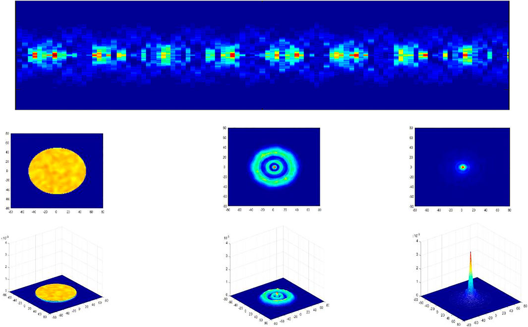
FIGURE 1. Localzation of light due to mode couplings from MM beam propagation in MM core fiber. (A) Spacial distribution of power change along the propagation with strong localization spots. (B) and (C): 2D and 3D spatial distribution of power at some locations of the fiber.
For this beam propagation method (BPM) simulation, at a wavelength of 1,060 nm, there are a large number of modes, and it is difficult to calculate the exact places and intensity of light localization. The BPM results however can give us some useful information to estimate hot-spot conditions in the waveguide. Note that, in high power fiber amplifiers and fiber lasers, if the intensities at those locations are higher than some threshold levels that are well known in different materials, the induced index changes can create defects in the fiber. In these high-power amplifiers and lasers with active ions, the defects (impurities.) along with the strong localizations of light can be causes for the creation of hot-spots inside the amplifier/laser.
In optical fiber communications, generally the transfer of information proceeds via encoded optical pulses traversing in single mode fiber. The communication lengths can be hundreds of kilometers. Innovations related to capacity have been the subject of intense research over the past decades due the commercial implications. These innovations have included the implementation of erbium doped amplifiers, wavelength division multiplexing, high spectral efficiency encoding and now possibly space division multiplexing [4]. A major focus of space division multiplexing is MIMO, multiple input-multiple output information processing. MIMO is currently being used commercially in wireless communications. Adapting this to fiber communications in multimode or few mode fiber has not been straightforward due to the random mode coupling that occurs. The mode coupling is essentially a scattering event occurring often on the order of meter lengths and less. In single mode fibers however, adaptive equalization using MIMO digital signal processing is being considered for commercialization [4]. This is because the MIMO process is well adapted here. In an alternative to MIMO, principal mode transmission has been proposed to overcome mode dispersion [5]. Principal modes do not experience dispersion to first order in frequency [5, 6] making it possible to utilize these modes to transmit information in few modes even in the presence of strong mode coupling.
Principal mode propagation in optical fiber is a localization of a group of guided modes at the output of a multimode fiber in both the frequency and time domains. Localization of waves in general has been itself a subject of worldwide research beginning with the seminal work of P. W. Anderson [7]. Light wave localization in complex media results in several fascinating subjects, including random lasers as well as quasiperiodic and deterministic photonic structures. Random laser research began with the work of Letokhov [8] and experimentally with Gouedard [9]. Photonic structures such as quasi periodic Fibonacci crystals [10] lead to light localization.
As mentioned, light can be optically processed to localize in time at the output of multimode fibers These modes are characterized as principal modes. The principal modes are a superposition of the guided modes existing within the multimode fiber. In the absence of polarization properties, these guided modes and their propagation can be modeled with the scalar wave equation [11]. When including polarization, the full vector wave equation is required [11].
In the following section we will show how principal modes are superimposed from guided modes. We will also discuss how they are fundamentally characterized. Then in section 3, we will show measurement methods, using both the “matrix transfer” and the time delay methods. In section 4, we give an outlook.
2 Principal Modes in Optical Fiber, Single Mode and Multimode
Principal modes are a superposition of the guided modes within a multimode or few mode optical fiber. If N guided modes exist within a fiber, there will be N principal modes and the principal modes are a specific superposition of these guided modes. Attenuation is an issue since principal modes are derived using the guided modes assuming there is no attenuation. The effect that attenuation has on these modes is a current subject of research. The principal modes are orthogonal with one another and the output principal modes are not the same as the input principal modes. This superposition includes not only amplitude values but also the phase relationship among the modes. Since the guided modes propagate at different speeds, there can be a broadening in time of the a given superimposed mode at the output. This can be considered a second order effect. Also, there can be a spread spatially of the superimposed modes as compared with the spatial spread of a specific guided mode at the output of the fiber. But the important aspect of these modes is that at the output the information is localized in that the information transfer is localized onto only one of these orthogonal superimposed modes [5].
Single mode fiber can send information over transoceanic distances with repeaters. Signals are amplified but not detected until they reach the final output destination. The first guided–spatial mode within an optical fiber is termed the LP01 mode in the wave equation or the HE11 mode using the full vector equations. For these systems to work, the separation of the two polarized modes cannot be separated to within a fraction of the total pulse width. The time difference between the polarization states is characterized as polarization mode dispersion (PMD). PMD was a subject of high interest in the 1990s as new long distance transoceanic and transcontinental systems were being deployed. Characterizing PMD was accomplished using the concept of two mode–principal modes. This is because due to mode coupling the arrival time difference between the two output polarization states varies with time and the maximum difference is in fact that of the two principal modes. Gordon and Kogelnik [12] published an excellent review of the fundamentals of principal modes and how they relate to PMD. They show analytically how the principal modes and therefor their time delay differences using both the Jones vector and Stokes vector methods. Important to the analysis are the 2 × 2 Pauli spin matrices enable one to quantify the input and output launch conditions so that the principal modes and PMD can be determined. In this analysis in addition to a matrix transfer method they also derive a time delay method. It can be said that the principal mode concept is a generalization of the polarization mode dispersion concept.
Due to the many modes within a multimode fiber, the coupling process is indeed complex. In the early days of optical communications, digital pulses were sent through multimode rather than single mode fibers. LED (Light emitting diodes) sources rather than laser were used due to their availability and single mode connectivity was an issue. Coupling among modes was studied extensively since this affected transmission capacity. Typical fiber parameters were a = 50 micron core and a refractive index of 0.015. The index profile was expressed as with radius as:
where r is the radial position, a is the cladding radius and Δ is the difference in the refractive index between core and cladding divided by the index value at r = 0. The value of parameter α is close to 2 but varies with wavelength. This value at a wavelength of 1,550 nms is approximately 1.85 and at 800 nms is approximately 2.25 for germania doped optical fibers. Also, these values vary slightly from here depending on chemical composition and on doping levels as discussed in reference 13. The guided mode properties for these profiles are discussed extensively by Keck [13]. The modes are characterized with radial, μ, and azimuthal, υ, parameters. Degenerate modes exist for combined values of these parameters,
The total number of modes is large,
k is the inversely to the propagating wavelength and M is the maximum value of m and is given by
Experimentally and theoretically it was shown that coupling among pulses through multimode fibers occurs predominately within modal groups and very little coupling occurs between modal groups, [15]. In a 20 km length of 50 micron core fiber, mode coupling as well as modal compensation occurred. An understanding of these coupling and compensating effects in fiber are essential for a complete understanding of principal mode propagation in these fibers and this publication is helpful in this regard.
Principal mode transmission in multimode fibers were first proposed first by S. Fan and J. Kahn [5]. They showed that the principal modes do not suffer from modal dispersion to first order in frequency and form an orthogonal bases at both the input and output ends of a waveguide. These modes were well described fundamentally by M. Shemirani and J Kahn [16]. They also discussed adaptive methods for tracking these modes in time. Adaptive methods to enable high speed transmission through these fibers are discussed, including numerical simulations, experimental demonstrations, and adaptive optical algorithms. See also, Shen et, al, [17]. Very recently these methods have been significantly enhanced for communications and other applications, Metthes [18].
It is very important to note that in a deployed optical fiber transmission fiber, the principal modes vary in time. This is because the mode coupling and hence the superposition of guided modes within the fiber vary with temperature changes, etc. There have not been any reported measurements of the time scale with which these modes vary. But the time scale at which the two principal polarization modes vary in deployed single mode fiber varies greatly with deployment conditions. These states can remain stable within only seconds for certain deployment conditions but remain stable over weeks in other conditions [19].
3 Principal Mode Characterization
Principal modes in optical fibers were first measured by J. Carpenter et. al [20, 21]. They termed their method the Matrix Transfer Method. Light was launched and detected in a 2-m length fiber. Launching and detecting into the modes, both principal and guided, was implemented using spatial light modulators. The experimental arrangement is shown in Figure 2. They showed that Eisenbud–Wigner–Smith eigenstates, originally proposed in nuclear scattering also occur in optics. Despite spatiotemporal scattering during propagation these states arrive at the output un-scattered.
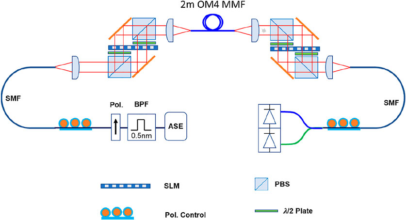
FIGURE 2. The mode decomposition and mode generation setup proposed in [5].
3.1 A Matrix Transfer Method for Characterizing Principal Modes
Carpenter et al. [21], showed that 110 × 100 input principal modes can be determined at the input and output of a multimode fiber. The figure below is a representation of their experiment. Spatial light modulators enabled them to address and measure each individual input and output guided mode. Using this they determined the transfer matrix, from which they were able to the principal input and output modes. See below:
W. Xiang also characterized both numerically and experimentally many principal modes in a graded index fiber [22, 23]. They showed that the group delay matrix coincides with the Wigner–Smith time delay matrix.
They discussed how Principal mode transmission enables the transfer of information through an optical fiber even in the presence of strong mode coupling, scattering. The input and output Principal modes are superpositions of the vector eigen modes of the fiber. Even though there are delay differences among these eigen modes, there is a localization of information transfer and it is possible to transmit N principal modes in a fiber consisting of N eigen modes since these propagating modes are mutually orthogonal. This enables a critical medium for the exploration of these Wigner–Smith eigen states. Furthermore, there is interest in relating Wigner–Smith eigenfunctions to Anderson localization. See for example Ossipov [24].
W. Xiang et. al. both calculated and experimentally measured the mode transfer matrix for 50 micron–diameter core, 0.2 NA optical fiber guiding 120 guided modes for one polarization [22, 23]. Figure 3 shows the field transmission matrices for the situations of both strong and weak coupling. The weak coupling case is for the fiber as deployed and the strong mode coupling case is when an applied stress is applied.
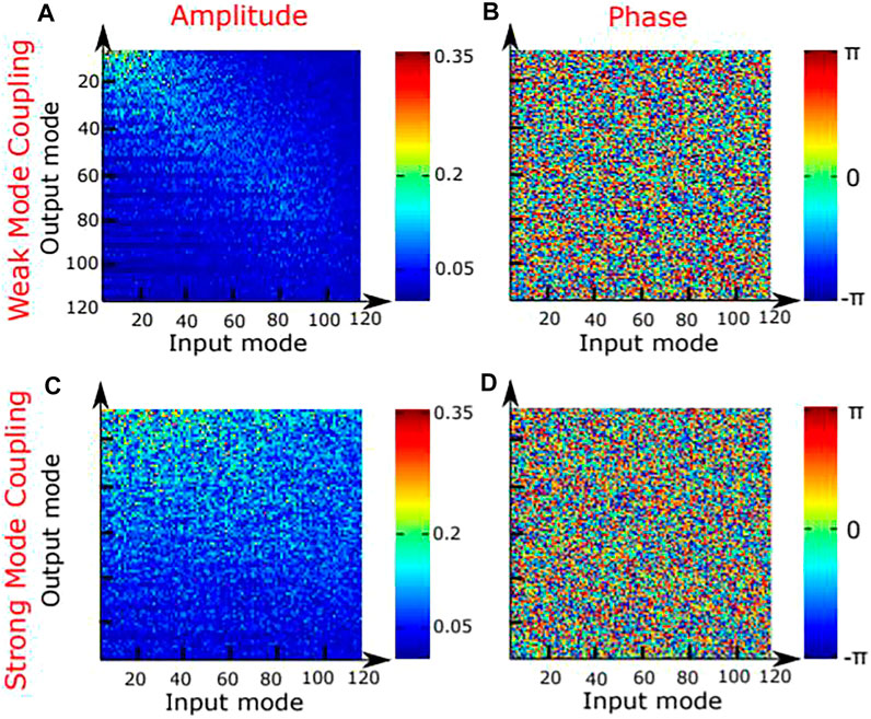
FIGURE 3. Input and output–amplitude and phase for a fiber in the presence of weak and strong mode coupling.
They also measured and calculated the amplitude and phase of the principal modes in this fiber as shown in Figure 4.
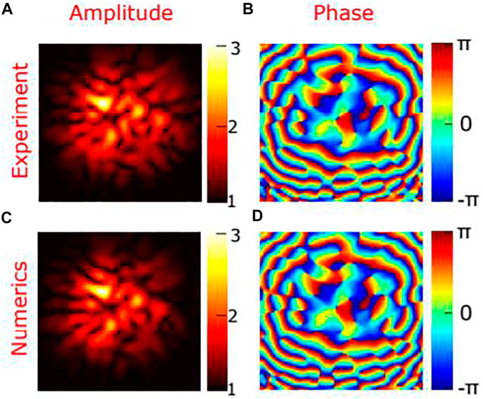
FIGURE 4. Comparison of a numerical simulation with experiment for fiber in the presence of mode coupling.
Determining the Principal modes using the mode transfer matrix becomes more complex for longer lengths of fiber, meters, since this method essentially requires the deconvolution of a multimode interference pattern. Typically, the resolution of multimode interference patterns blurs as distances increases. The ultimate length of which the matrix transfer method is useful as function of fiber parameters, length and deployment is not yet known.
3.2 B Time Delay Method
Alternative to the matrix transfer method, is the direct - time delay method proposed by Mlione, Nolan and Alfano [6]. This method requires a separation in time of the fiber’s guided modes at the fiber output and as such performs better with longer lengths in general. This method is an extension of polarization methods using signal delays for the characterization of polarization mode dispersion in single mode fiber [25]. The authors proposed measuring the required time delays using polarization dependent launch conditions specified by SU(2) mathematics and the Pauli spin matrices. In the process of determining the polarization mode dispersion, PMD, of the fiber, the method also determines the two principal modes of the fiber. Figure 5 shows the input polarization mode distributions used to generate the principal modes. The authors in reference 6 generalized this method using SU(N) group symmetry considerations and mathematics. Thus, multimode fiber is an excellent medium for the investigation of the Wigner–Smith eigen states and the localization of light using the SU(N) algebra. Experimental verification of the method was given by T. Nguyen et. al [26]. Figure 6 shows the generators for SU(N). Implementation of this method requires measuring the time delays of the N guided vector modes. In a gradient index, OM4, multimode fiber these delays are on the order of hundreds of nanoseconds and become more pronounced over longer lengths of fibers. For this reason, it can be expected that the time delay method more useful using longer lengths of fibers, while interferometric methods will be more useful for very short lengths of fibers, on the order of meters.
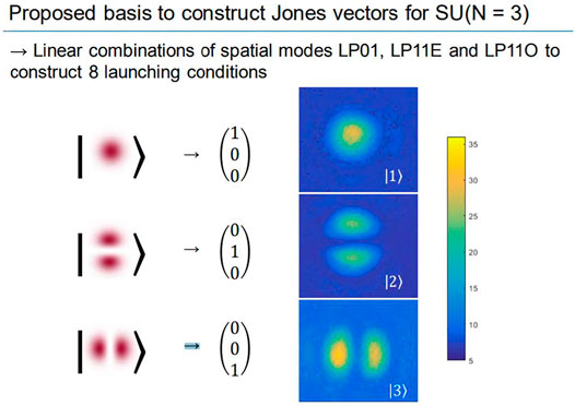
FIGURE 5. The eigen modes of the fiber to be superimposed in order to determine the Principal Modes.
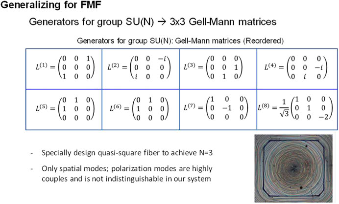
FIGURE 6. Gell Mann matrices used to generate the modal launch conditions for a 3 mode fiber.
There is interest in reducing the number of launch and detecting measurements using the time delay method, Wood et al [27]. Yang and Nolan [28] showed that this number can be reduced to 3N–2 input launch conditions when the time delays are large and discrete. For large N this becomes very important because the increase in launch becomes linear with N rather than quadratic. Another issue is noise and attenuation. Roudas et. al [29]. numerically investigated and found the optimum launch conditions for this situation.
The authors in reference 21, T Nguyen et al. characterized a 1 5 Km special few mode fiber for the purposes of demonstrating the method, rather than to show the capabilities of the method under strong mode coupling. The fiber was 10% elliptical and guided the fundamental and the LP11O and LO11E higher order modes. This method requires a separation of the guided modes under specific launch conditions to enable a measurement. So, the fiber used here enables this, in the that there exist the 3 spatial modes well separated in time, LP01, PL11E and LP11O modes. In this experiment, they used a T-Light Laser, with an output power of 0.12 W. And a wavelength of 1,560 nms.
The mathematics used to specify the amplitude and phase relationships of the 8 guided modes to be launched into the fiber. These modes are linear combinations of the guided modes. Then using the measured output delays, the calculated input principal modes are calculated.
The procedure in Figure 7 was as follows: A.) 8 launch conditions were generated, B.) the mean time delays were measured, C.) Solved 8-time delays from a system of linear equations, D and E.) solve the Wigner - Smith equation and the 3 principal modes.
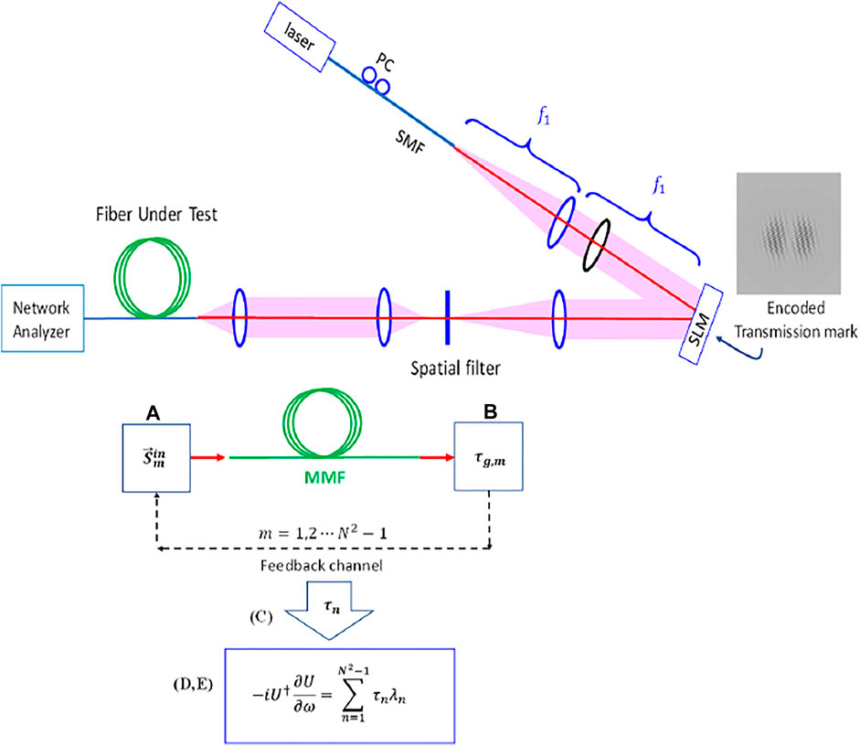
FIGURE 7. Experimental arrangement to characterize the 3 mode fiber. Pulses are launched, through a spatial light modulator, onto the guided modes of the fiber. Eight separate launch conditions, as specified by the Gell Mann matrices, are launched to measure 8 different mean group delays. These delays are then inserted into the eigenvalue equation to determine the 3 eigenfunctions, principal modes.
This is shown pictorially below for the case of launching the three specific LP01, LP11E and LP11O. The mathematical formalism is related to the guided mode input fields.
Below the relationship between the mathematical formalism is shown for the required 8 superimposed modes at the input.
The table in Figure 8, shows the evaluated parameters for the three determined principal modes, PM1, PM2, PM3. Each of these principal modes are composed of three guided modes. LP01, LP11E and LP11O. The table shows how to launch each of the principal modes. For each of the three principal mode the table shows the amplitude and angle, launch values, of the three composing guided modes.
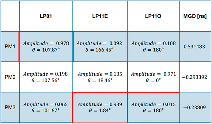
FIGURE 8. Values of the determined Principal modes.
Figure 9 shows the output pulse shapes when a principal mode is launched at the input. Each of the output modes are orthogonal to one another. But the centroid of each arrives at a different time.
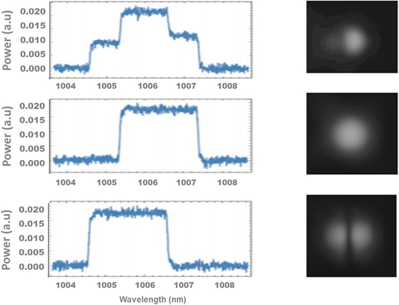
FIGURE 9. Output pulses of the launched Principal modes, PM1 and PM3.
4 Outlook
Principal mode transmission in optical fibers under the presence of mode coupling, demonstrates the information transfer through a scattering medium. Principal modes are shown to be similar to Wigner–Smith eigen states. These modes will possibly be used to further increase the information transfer capacity of optical fibers. Methods to characterize these fibers including the matrix transfer method and the signal time delay method have been discussed. It is proposed that the matrix transfer method is more useful when characterizing short lengths of fibers and that the time delay method mode useful when characterizing long lengths, when the required time delays can be resolved. This is because the matrix transfer method is a multimode interference method and these methods generally become indistinguishable for increasing filter length. On the other hand, the time delay method requires a separation in time, of the fibers guided for measurement. And these guided modes in general separate better with distance.
However there have been no studies systematically characterizing these methods as a function of fiber parameters, including the numbers of modes and fiber lengths. Also, it is important to remember that the principal modes in a deployed fiber transmission system will change in time as the mode coupling changes. This is variation in time will most likely be a function of the fiber parameters including numbers of modes and lengths involved.
Principal mode transmission and the localization of light through a scattering medium is of interest beyond optical communication. It can be expected that there will be other applications such as imaging for example.
Author Contributions
DAN contributes on the theory of principle modes and experiment results. DTN contribute on simulation.
Conflict of Interest
Authors DAN and DTN were employed by Corning Inc. Corning, New York, United States.
Publisher’s Note
All claims expressed in this article are solely those of the authors and do not necessarily represent those of their affiliated organizations, or those of the publisher, the editors and the reviewers. Any product that may be evaluated in this article, or claim that may be made by its manufacturer, is not guaranteed or endorsed by the publisher.
References
1. Ghulinyan M, Pavasi L. Light Localization and Lasing. Cambridge University Press, Cambridge, United Kingdom (2015). doi:10.1017/CBO9781139839501
2. Rohrer C, Kleem G, Ahmed MA, Graf T. Analysis of Fundamental-Mode Beam Transport in Highly Multimode Fibers. J Lightwave Technol (2017) 35:3637–42. doi:10.1109/jlt.2017.2718182
3. Gloge D. Optical Power Flow in Multimode Fibers. Bell Syst Tech J (1972) 51:1767–83. doi:10.1002/j.1538-7305.1972.tb02682.x
4. Richardson DJ. New Optical Fibers for High Capacity Optical Fibers. Phil Trans R Soc (2016) 374. doi:2014044doi:10.1098/rsta.2014.0441
5. Fan S, Kahn JM. Principal Modes in Multimode Waveguides. Opt Lett (2005) 30:135–7. doi:10.1364/ol.30.000135
6. Milione G, Nolan DA, Alfano RR. Determining Principal Modes in a Multimode Optical Fiber Using the Mode Dependent Signal Delay Method. J Opt Soc Am B (2015) 32(1):143–9. doi:10.1364/josab.32.000143
7. Anderson PW. Absence of Diffusion in Certain Random Lattices. Phys Rev (1958) 109:1492–505. doi:10.1103/physrev.109.1492
8. Letokhov VV. Generation of Light by a Scattering Medium with Negative Resonance. Sov Phys JETP (1968) 26:835–40.
9. Gouedard C, Auzel F, Migus A, Husson D, Sauteret C. Generation of Spatially Incoherent Short Pulses in Laser-Pumped Neodymium Stoichiometric Crystals and Powders. J Opt Soc Am B (1993) 10(12):2358–63. doi:10.1364/josab.10.002358
10. Ledermann A, Renner M, Von Freymann G. .Chapter 7 in M Ghulinyan, and L Pavasi, Light Localization and Lasing. Random and Quasi-random Photonic Structures, Cambridge University Press Cambridge, United Kingdom (2015).
11. Black RJ, Gagnon L. Optical Waveguide Modes, Polarization Coupling and Symmetry. McGraw-Hill, New York USA, (2010).
12. Gordon JP, Kogelnik H. PMD Fundamentals: Polarization Mode Dispersion in Optical Fibers. Proc Natl Acad Sci (2000) 97:4541–50. doi:10.1073/pnas.97.9.4541
13. Keck DB. In: M Barnoski, editor. Optical Fiber Waveguides, Chapter 1 in Fundamentals of Optical Fiber Communications. Academic Press New York USA, (1981). doi:10.1016/B978-0-12-079151-4.50005-4
14. Olshansky R. Mode Coupling Effects in Graded-Index Optical Fibers. Appl Opt (1975) 14:935–45. doi:10.1364/ao.14.000935
15. Nolan D, Hawk R, Keck D. Multimode Concatenation – Modal Group Analysis. J Lightwave Tech (1987) 5:1727–32. doi:10.1109/jlt.1987.1075464
16. Shemirani M, Kahn J. Adaptive Compensation of Multimode Fiber Dispersion by Control of Launched Amplitude, Phase, and Polarization. J Lightwave Technol (2010) 28:2627–2639. doi:10.1109/JLT.2010.2058092
17. Shen X., Kahn JM, Horowitz MA. Compensation in Multimode Fibers by Adaptive Optics. Opt Lett (2004) 2985–7. doi:10.1049/cp:20050501
18. Metthes M, Bromberg Y, de Rosny J, Popoff S. Learning and Avoiding Disorder in Multimode Fibers. Phys Rev X (2021) 11:021060. doi:10.1103/physrevx.11.021060
19. Brodsky M, Frigo NJ, Boroditsky M, Tur M. Polarization Mode Dispersion of Installed Fibers. J Lightwave Technol (2006) 24:4584–99. doi:10.1109/jlt.2006.885781
20. Carpenter J, Eggleton BJ, Schröder J. 110x110 Optical Mode Transfer Matrix Inversion. Opt Express (2014) 22:96–101. doi:10.1364/oe.22.000096
21. Carpenter J, Eggleton BJ, Schröder J. Observation of Eisenbud-Wigner-Smith States as Principal Modes in Multimode Fibre. Nat Photon (2015) 9:751–7. doi:10.1038/nphoton.2015.188
22. Xiang W, Ambichi P, Bromberg Y, Redding B, Rotter S, Cao H. Spatio-temporal Control of Light Transmission through a Multimode Fiber with strong Mode Coupling. ArXiv (2016) 117(5):04646. doi:10.1103/PhysRevLett.117.053901
23. Xiang W, Ambichi P, Bromberg Y, Redding B, Rotter S, Cao H. Principal Modes in Multimode Fibers: Exploring the Crossover from Weak to strong Mode Coupling. Opt Express (2017) 25(3):2709–24. doi:10.1364/oe.25.002709
24. Ossipov A. Scattering Approach to Anderson Localization. Phy Rev Letters 121(7) (2018) 1803–01828. doi:10.1016/b978-012639845-8/50008-3
25. Nelson L, Jopson R, Kogelnik H, Gordon J. Measurement of Polarization Mode Dispersion Vectors Using the Polarization-dependent Signal Delay Method. Opt Express (2000) 6:158–67. doi:10.1364/oe.6.000158
26. Nguyen T, Khrapko R, Roudas I, Nolan D. Experimental Characterization of Principal Modes of Multimode Fiber Using the Mode-dependent Signal Delay Method. Private Communication (2018).
27. Wood W, Miller W, Mlejnek M. A Generalized Perspective on the Coherent Multimode Optical Field and Mode Coupling Equations. IEEE Quant Electron (2015) 51:1–6. doi:10.1109/jqe.2015.2439513
28. Yang J, Nolan DA. Using State Tomography for Characterizing Input Principal Modes in Optically Scattering Medium. Opt Express (2016) 24:27691–701. doi:10.1364/oe.24.027691
Keywords: principal modes, light localization, few mode optical fiber, mode coupling, multimode propagation
Citation: Nolan DA and Nguyen DT (2021) Light Localization and Principal Mode Propagation in Optical Fibers. Front. Phys. 9:713085. doi: 10.3389/fphy.2021.713085
Received: 21 May 2021; Accepted: 08 September 2021;
Published: 22 September 2021.
Edited by:
Jifeng Liu, Dartmouth College, United StatesReviewed by:
Tian Gu, Massachusetts Institute of Technology, United StatesCuicui Lu, Beijing Institute of Technology, China
Copyright © 2021 Nolan and Nguyen. This is an open-access article distributed under the terms of the Creative Commons Attribution License (CC BY). The use, distribution or reproduction in other forums is permitted, provided the original author(s) and the copyright owner(s) are credited and that the original publication in this journal is cited, in accordance with accepted academic practice. No use, distribution or reproduction is permitted which does not comply with these terms.
*Correspondence: Daniel A. Nolan, NolanDA@corning.com