Self-Mixing Signal Characteristics of Complex-Coupled Distributed-Feedback Terahertz Quantum-Cascade Lasers
 Lei Ge1
  Ning Yang1*
  Jian Wang2 Weidong Chu1 Suqing Duan1
  Yan Xie3
  Yingxin Wang3
  Lianhe Li4 Edmund Linfield4
- 1Institute of Applied Physics and Computational Mathematics, Beijing, China
- 2Department of Physics, Beijing Jiaotong University, Beijing, China
- 3Department of Engineering Physics, Tsinghua University, Beijing, China
- 4School of Electronic and Electrical Engineering, University of Leeds, Leeds, United Kingdom
Self-mixing interference (SMI) in terahertz quantum cascade lasers (THz QCLs) is one of the significant approaches for coherent THz imaging and sensing techniques. Here, the output characteristics of SMI in distributed feedback (DFB) THz QCLs from the index-to the gain-coupling regimes are studied using the coupled wave theory and the multi-mode rate equation method. A mode hopping phenomenon is found to occur when the DFB coupling factor changes from index-coupling to gain-coupling, and the characteristics of the self-mixing signals of DFB-QCLs change greatly with this mode hopping. With the modulus of the coupling factor fixed and its argument varied from 0 to π/2, an extreme point of the self-mixing frequency and power signals of DFB-QCLs is found at π/9 due to the mode hopping. For index-coupling dominated DFB-QCLs, both the varying ranges of the self-mixing frequency signals and amplitudes of power signals increase with increasing DFB coupling factor argument. For gain-coupling dominated DFB-QCLs, with increasing argument value, the amplitude of the self-mixing power signal increases, but the varying range of the self-mixing frequency signal decreases. With the argument of the coupling factor fixed, we also found that the varying ranges of the self-mixing frequency signals decrease with increasing modulus for both index-coupling dominated and gain-coupling dominated DFB-QCLs. For index-coupling dominated DFB-QCLs, the amplitudes of the self-mixing power signals decrease with increasing modulus; however, the amplitudes of the self-mixing power signals of gain-coupling dominated DFB-QCLs increase. With the argument of the coupling factor fixed, for index-coupling dominated DFB-QCLs, we found that the varying ranges of the self-mixing frequency signals and amplitudes of power signals decrease with the increasing modulus. For gain-coupling dominated DFB-QCLs, with the coupling factor modulus increasing, the varying ranges of the self-mixing frequency signals decrease, however, the amplitudes of the self-mixing power signals increase. These results may help with the application of DFB-QCLs to self-mixing interferometers.
1 Introduction
Terahertz Quantum cascade lasers (THz QCLs) are compact and coherent THz light sources that generate optical transitions between conduction subbands in semiconductor multiple-quantum-well structures [1]. Together with their unipolar nature and wide coherent sensing range, QCLs can meet the increasing needs of applications in materials imaging, THz communication technology, atmospheric science, spectroscopy, and frequency metrology [2].
Self-mixing interference (SMI) (also known as laser feedback interference) is a sensing method that uses measurements of the change in the operating parameters of the laser under optical feedback. In contrast to traditional sensing systems, which employ the laser as a source and an optical interferometer to split and recombine the beam, SMI is based on the interaction of the in-cavity field with the back-scattered field from a target, which induces a modulation in amplitude of the optical emission frequency, power, and terminal voltage [3]. The use of SMI in THz QCLs has been studied in-depth, and it could be a promising solution for THz sensing of displacement, vibration, and velocity, and 2D/3D THz imaging [4]. Under optical feedback, QCLs can maintain a more stable working state than diode lasers because of the absence of relaxation oscillations. This is attributed both to high photon-to-carrier lifetime ratios and a negligible linewidth enhancement factor (α < 1) [5, 6].
Typical SMI prefers a stable, single-mode laser with low linewidth, which makes the data processing in a concise way. However, most Fabry–Pérot (FP) QCLs work with a broad emission linewidth in a multi-mode regime. Common candidates are distributed feedback quantum cascade lasers (DFB-QCLs) incorporating a first-order Bragg DFB grating into a standard QCL waveguide, which can provide more strictly single-mode emission with a high side mode suppression ratio (SMSR) [7–9]. Moreover, based on a second- or fourth-order Bragg gratings, some researches achieved high power surface emitting THz QCLs [10]. Rencently, a new model was designed to predict resonant mode characteristics of THz QCLs with a first, second, and third-order DFB-QCLs [11]. And wavelength beam-combining of four terahertz THz DFB-QCLs is demonstrated using low-cost THz components [12]. Base on the self-mixing technique, an experiment has been made to measure the linewidth enhancement factor α [13]. A newest experiment has made an extensive study of the linewidth enhancement factor α of a DFB-QCL, and it used the SMI technique to obtain α factors for current biases up to more than 100% of the threshold current [14]. Typically, the DFB gratings are either purely index coupled, purely gain coupled, or complex coupled, according to adjustments in the etching process based on theory and experience. From this point of view, some early studies investigated the properties of SMI in index-coupled diode lasers using the coupled wave theory, and the results show that the cosine-like self-mixing signal is similar to that from a single-mode FP laser [15, 16]. Furthermore, some studies also have shown that SMI sensors based on gain-coupled DFB lasers exhibit high accuracy [17]. However, a DFB laser with a grating etched into its upper cladding layer has an increased waveguide loss through the top contact layer, and this may in turn decrease its performance [18]. Recently, as a result of their performance, complex-coupled DFB-QCLs have received considerable attention in terms of both theory and experiments; in contrast to FP-QCLs and index-coupled DFB-QCLs, they have a reduced threshold current density and an increased power output via the introduction of built-in longitudinal modulation of the optical gain [19, 20].
A complex-coupled DFB THz QCL has a DFB grating etched into the top surface of the active region across the upper cladding layer; therefore, these devices have mixed index and gain coupling, and they also have a complex coupling factor [18]. Complex-coupled and gain-coupled DFB lasers have shown significant improvements in some studies in terms of reduced spatial hole burning and enhancement of modulation bandwith [18, 21]. In addition, experimental and theoretical works have also reported that complex-coupled and gain-coupled DFB lasers with a very large gain coupling show the potential for lower feedback sensitivity when compared with other DFB lasers [22, 23].
As noted above, complex-coupled and gain-coupled DFB lasers are more appropriate for use in SMI systems, especially in the case of weak optical feedback. However, in experiments, it is difficult to fabricate pure gain-coupled gratings because variations in gain cause variations in carrier density, which in turn cause variations in refractive index. In experiment, the complex coupling of DFB-QCLs has been attainable by chemical wet etching of the top contact layer to a certain depth, with the DFB grating etched close to the active region [24]. Recent studies on complex-coupled DFB-QCLs have reported that they exhibit excellent performance, with high-power continuous-wave, room temperature operation, and single-mode emitting with a high SMSR [25, 26]. However, there have so far been few in-depth studies of the dynamics of complex-coupled DFB-QCLs. In particular, the differences between complex-coupled and index-coupled DFB-QCLs in terms of their response rules for optical feedback are in need of detailed investigation.
The Lang–Kobayashi (L–K) equations are generally employed to study the dynamical behavior of SMI in FP-QCLs. However, the L–K equations cannot be simply applied to DFB-QCLs under optical feedback, despite the fact that several studies have used modified L–K equations to this end [17]. Here, we use the coupled wave theory to describe the mode-coupling phenomenon and calculate the emission power of complex-coupled THz DFB-QCLs under SMI using the multi-mode rate equation method. This model was implemented in our early study on SMI in index-coupled DFB-QCLs with a purely real index-coupling factor [27].
The remainder of this article is organized as follows. In Section 2, the coupled wave theory and the multi-mode rate equation method for the simulation of SMI in DFB-QCLs are presented. In Section 3, the basic output characteristics of SMI in DFB-QCLs of pure index coupling, complex coupling, and pure gain coupling are discussed. Finally, Section 4 presents our conclusions.
2 Theoretical Model of SMI in THz Complex-Coupled DFB-QCLs
The coupled wave theory is an important method for simulating the longitudinal modes distributed in a DFB structure. Figure 1 shows a schematic drawing of a complex-coupled DFB-QCL with a first-order grating, which mainly radiates in the vicinity of Bragg wavevector β0 = 2π/(Λneff), where Λ is the grating period, and neff is the effective refractive index of the medium. Generally, the first-order grating for a QCL is pure real index-coupled grating or complex-coupled one with a small imaginary part that depends on the etching depth. At least in theory, there are also gratings with a pure imaginary coupling factor, i.e., gain-coupled gratings, although they are not common for QCLs.
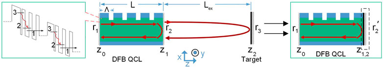
FIGURE 1. Schematic of a DFB-QCL with an external target and an equivalent reflection coefficient r2′.
In accordance with the coupled wave theory, starting from the scalar wave equation and using small-perturbation assumptions, the coupled wave equations are given as [22]:
where F(z) is the forward-running envelop wave and B(z) is the backward-running envelop wave. These two counter-running waves grow from the presence of gain, and they feed energy into each other due to Bragg scattering. The parameter k is the wave vector inside the medium of the laser and κ is the coupling factor, which measures the coupling strength between F(z) and B(z). For a complex-coupled DFB-Laser, κ is considered as a complex number satisfying
with κindex and κgain being real numbers measuring the coupling strength of the index and gain coupling of the grating, respectively. The laser modes in the cavity match the boundary conditions
where L is the length of the laser cavity, and r1 and r2 are the reflection coefficients of the laser facets. From Eqs 1–5 we get
where we adopt the expression of κ = κindex + iκgain from Eq. 3, and
As illustrated in Figure 1, when a target with reflection coefficient r3 reflects part of the light back into the laser cavity, on the consideration of weak optical feedback (r2r3 ≪ 1), we introduce an equivalent reflection coefficient to the emitting facet of the laser, describing the effect of SMI as [28]
where Lex is the distance from the laser emission facet to the target. In the case of strong optical feedback level, we suggest to refer to the expression of the equivalent reflection coefficient in [29]. From Eqs 6, 7, we can solve the wave vector k0 and the corresponding threshold gain gth with the influence of self-mixing feedback, and simultaneously solve the corresponding envelop waves F(z) and B(z). We can then obtain the self-mixing frequency signal with the formula
where νl is the mode frequency with optical feedback and νl0 is the solitary mode frequency.
In addition to the frequency signal, we use the multi-mode rate equation method to calculate the self-mixing power signal [30, 31]:
where: Sl is photon number of mode l; N3, N2, and N1 are the carrier numbers in the upper radiative, lower radiative, and collector levels, respectively; Z is the number of gain stages in the QCL; gl is the mode gain; Γ is the confinement factor; τl is the photon lifetime; β is the spontaneous emission factor; τij is the scattering lifetime between levels i and j; Iin is the injected current into level 3; q is the electron charge; and τout is the lifetime from level 1 into the subsequent miniband. The mode gain gl = G (N3–N2), where G is the differential gain coefficient. In this study, we use the assumption of no carrier losses between the subsequent stages with N1/τout = Iin/q. In order to gain a better understanding of the mode competition derived from the DFB grating structure with optical feedback, we assume that the value of gl is the same for the total modes in the laser cavity. The photon lifetime is written as
where: τw is the waveguide loss, which is the same for the total modes; and
in which the energy density
where ϵ0, μ0, and n0 are the dielectric constant, permeability, and refractive index of a vacuum, and n(z) is the refractive index at coordinate z.From Eqs 9–12, the optical power Pl is obtained as [32]
where hνl is the photon energy and R is the reflectivity of the output facet. We can then obtain the self-mixing power signal by the formula
where Pl and Pl0 are the optical power with and without optical feedback, respectively. It should be also noted that we assume the linewidth enhancement factor α = 0 for THz QCLs [5].
3 Results and Discussion
We assume the facet reflection coefficients to be r1 = r2 = 0.5 [33] and r3 = 0.001 [3], and the initial distance Lex = 47 cm from z1 to z2, which is a typical precondition in the application of SMI. In addition, the reflection coefficient of the emitting facet can be changed by the optimized reflectivity facet coatings [9]. Based on the definition of the feedback parameter
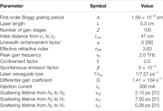
TABLE 1. Parameters used in the calculations.
3.1 Mode Hopping From Index Coupling to Gain Coupling
Figures 2A–C illustrate the time evolution results of the DFB-QCLs under self-mixing feedback. Here, we analyze the three cases of DFB coupling factors κ = 4, 4 + 0.5i, and 4 + 4i cm−1, which represent a pure index-coupled DFB-QCL, and a complex-coupled DFB-QCL with a weak gain-coupled part and a strong gain-coupled part, respectively. The time evolution simulations took an average of 0.5 ns to reach a steady state in these three cases. The corresponding output power spectra were obtained, and these are shown in Figures 2E–G for nine modes in the vicinity of first-order Bragg frequency. In Figures 2E–G, the numbers from −4 to 4 indicate the modes from the Bragg frequency to the side modes. It can be seen that the maximum power mode changes from mode 1 to mode 0 when the value of the imaginary part of the DFB coupling factor is increased from 0.5i to 4i. This mode hopping phenomenon occurs with the DFB-Laser changing from index-coupling dominating to gain-coupling dominating, as demonstrated in an early study [37]. Our simulations demonstrate that mode hopping also takes place in DFB-QCLs with SMI. By further examining the SMI signals, it can be seen that the characteristics of the SMI of DFB-QCLs also change with the occurrence of mode hopping.
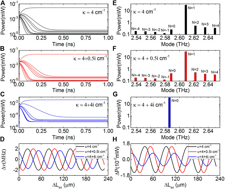
FIGURE 2. (A–C) Time evolutions of the power of nine modes in THz DFB-QCLs with r3 = 0.001, Lex = 47 cm, and κ = 4, 4 + 0.5i, 4 + 4i cm−1, respectively, using the multi-mode rate equations. (E–G) Self-mixing power spectra corresponding to (A–C). (D,H) Self-mixing frequency and power signals of the maximum power modes of DFB-QCLs with the same three values of κ.
Figures 2D,H show the self-mixing frequency and power signals of the maximum power (MP) mode of the DFB-QCLs with the three different values of κ. The plots show that the self-mixing signals have cosine-like waveforms. It should be noted here that we only show the self-mixing signals of the MP mode because the power of this mode and the total power of all the modes in the cavity are nearly equal for a stable single mode DFB-QCL. In the next section, we will show both the power signals of the MP mode and total modes in detail. We also found that the initial phase of the self-mixing signal shifts with κ. The variation in the varying range of the self-mixing frequency signals and amplitude of power signals with a complex κ is also discussed in the next section.
3.2 Self-Mixing Signal of Complex-Coupled DFB-QCLs
To explore the mode hopping and its influence on SMI, we firstly set the modulus of the coupling factor |κ| = 4 cm−1 and rewrite the complex coupling factor as κ = |κ|eiθ. With variation of the argument θ from 0 to π/2, we can obtain a series of self-mixing signals of DFB-QCLs from pure index coupling, complex coupling to pure gain coupling, as shown in Figure 3. In Figures 3A,B, it can be seen that there is an extreme point at about θ = π/9 where the self-mixing frequency and power signals of the MP mode have their maximum amplitudes. The power spectrum at θ = π/9 is also shown in the inset of Figure 3B. It can be seen that the SMSR at this extreme point decreases to 14 dB, which indicates that the DFB-QCL is not in a stable single-mode working state.
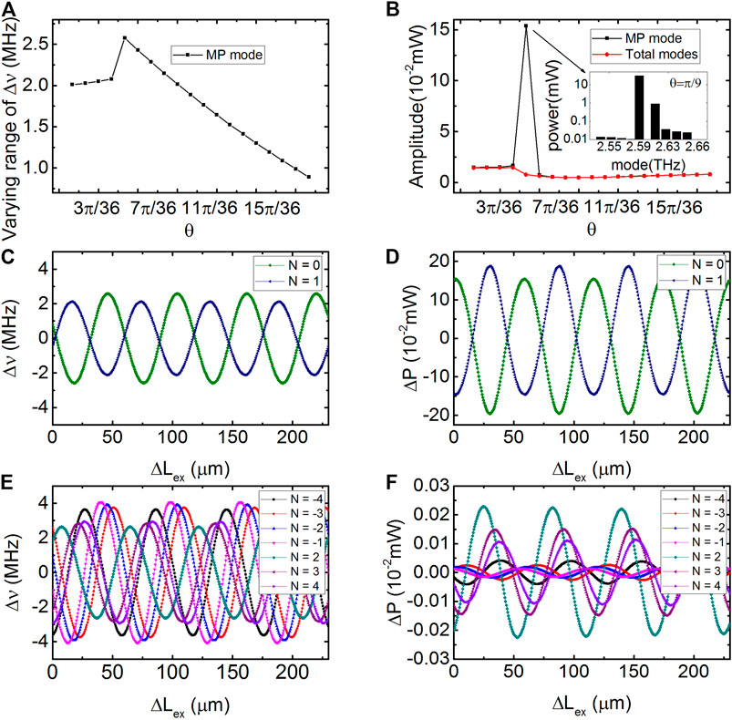
FIGURE 3. (A,B) Varying range of the self-mixing frequency signals and amplitude of power signals versus argument θ with κ = |κ|eiθ and |κ| = 4 cm−1. Inset of (B) shows the power spectrum at the extreme point. (C–F) Varying range of the self-mixing frequency signals and amplitude of power signals of modes (N = −4–4) as functions of ΔLex.
For pure index-coupled DFB-QCLs, our previous work showed that the varying ranges of both the self-mixing frequency and power signals decrease with increasing κ [27]. However, for the index-coupling dominated DFB-QCLs in Figure 3A, when θ increases from 0 to the extreme point θ = π/9, the varying range of the self-mixing frequency signal increases, and the amplitudes of the self-mixing power signals of both the MP mode and total modes in laser cavity also increase with variation of θ from 0 to π/9, as shown in Figure 3B. When θ continues increasing from the extreme point to θ = π/2, mode hopping takes place and the complex-coupled DFB-QCL becomes dominated by gain coupling. For gain-coupling dominated DFB-QCLs with θ increasing from π/9 to π/2, Figure 3A shows that the varying range of the self-mixing frequency signal decreases, which is similar to the pure index-coupled DFB-QCL. However, the amplitude of self-mixing power signal increases after mode hopping in Figure 3B. It is also found that the varying range of the self-mixing frequency signals and amplitude of power signals of a gain-coupling dominated DFB-QCL are smaller than those of an index-coupling dominated DFB-QCL. These behaviors of the self-mixing signal in a complex-coupled DFB-QCL are obviously different from those of pure index-coupled DFB-QCLs, and the amplitude of the self-mixing signal changes non-monotonically with increasing θ. The self-mixing signal of a DFB-QCL at this extreme point is notably different from that of the index-coupled and gain-coupled DFB-QCLs; hence, this phenomenon of SMI in DFB-QCLs may be of benefit for identifying the type of DFB grating.
Figures 3C–F illustrate the self-mixing frequency and power signals of all the modes in the simulations as functions of Lex at the extreme point θ = π/9. From this, we can see that the self-mixing signal of the MP mode is obviously different from the total modes as a result of mode hopping. Figure 3D shows that the amplitudes of the self-mixing power signals of mode 0 and mode 1 are of the same order and much larger than those of the other modes existing in the laser cavity as shown in Figure 3F. The other self-mixing power signals in Figure 3F are in the same level. However, we found that the varying ranges of the self-mixing frequency signals of all modes in the laser cavity are in the same level. And Figures 3C,E shows the varying ranges of the self-mixing frequency signal corresponding to the modes in Figures 3D,F.
We now examine the characteristics of the self-mixing signal as a function of κ with fixed argument values. Figures 4A–C show the varying ranges of the self-mixing frequency signal as functions of |κ| values from 4 to 10 cm−1 with θ = π/18, 5π/18, and 8π/18, respectively. With these values of |κ|, the DFB-QCLs are in a single-mode working state, and the corresponding SMSR versus |κ| are shown in the insets. It is found that no matter the value of θ, the varying ranges of the SMI frequency signals decrease with increasing |κ|. This response behavior of complex-coupled DFB-QCLs is the same as that of pure index-coupled DFB-QCLs, and this phenomenon can also be found from the L–K equations [27]. Figures 4D–F show the amplitudes of the self-mixing power signal versus |κ|. For the index-coupling dominated DFB-QCLs with θ = π/18, Figure 4D shows that the amplitude of the self-mixing power signal decreases with increasing |κ|, and this is also true in the pure index-coupled case. However, for the gain-coupling dominated DFB-QCLs with θ = 5π/18 and 8π/18 in Figures 4E,F, it can be seen that the amplitudes of the self-mixing power signals increase with |κ|. This change rule for gain-coupling dominated DFB-QCLs is opposite to that for the index-coupling dominated DFB-QCLs (Figure 4D).
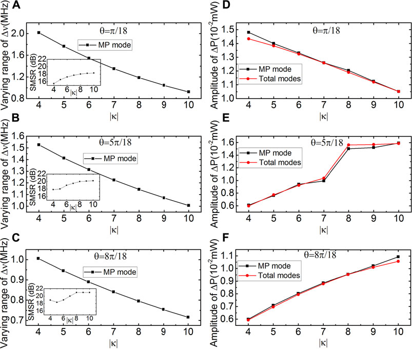
FIGURE 4. (A–C) Varying range of self-mixing frequency signals of the maximum power mode versus |κ| with θ = π/18, 5π/18, and 8π/18, respectively. Insets of (A–C) shows the SMSR versus |κ|. (D–F) Amplitude of self-mixing power signals of the maximum power mode and the total modes versus |κ| with θ = π/18, 5π/18, 8π/18, respectively.
4 Conclusion
This study explored the output characteristics of self-mixing interference in terahertz distributed feedback quantum cascade lasers in the index-, complex-to gain-coupling regimes. Keeping the modulus of the coupling factor fixed while varying its argument from 0 to π/2, we found that extreme points occur at π/9 in the self-mixing frequency and power signals of DFB-QCLs. We also showed that the self-mixing frequency and power signals change with DFB coupling factor before and after a mode hoping phenomenon occurs. In the case of index-coupling dominated DFB-QCLs with a fixed modulus, the amplitudes of the self-mixing frequency and power signals increase while increasing argument. For gain-coupling dominated DFB-QCLs, when the argument of coupling factor is increased, the amplitude of the self-mixing power signal increases; however, the varying range of the self-mixing frequency signal decreases. With a fixed coupling factor argument, for index-coupling dominated DFB-QCLs, the varying ranges of the self-mixing frequency signals decrease with the increasing modulus. For coupling dominated DFB-QCLs, increasing the modulus of coupling factor decreases the varying ranges of the self-mixing frequency signal; however, the amplitude of the self-mixing power signals increase increases with increasing modulus. These findings will be helpful in investigating the nonlinear dynamics of complex-coupled self-mixing interference in THz DFB-QCLs, and this may be valuable for the application to THz DFB-QCLs in self-mixing sensing systems.
Data Availability Statement
The raw data supporting the conclusion of this article will be made available by the authors, without undue reservation.
Author Contributions
NY, LG, WC, LL, and EL contributed to conception and design of the study. LG performed the simulation. LG, NY, SD, YX, and YW performed the data analysis. LG wrote the first draft of the manuscript. NY wrote sections of the manuscript. All authors contributed to manuscript revision, read, and approved the submitted version.
Funding
The work was financially supported by the National Natural Science Foundation of China Joint Fund (Grant No. U1730246).
Conflict of Interest
The authors declare that the research was conducted in the absence of any commercial or financial relationships that could be construed as a potential conflict of interest.
Publisher’s Note
All claims expressed in this article are solely those of the authors and do not necessarily represent those of their affiliated organizations, or those of the publisher, the editors and the reviewers. Any product that may be evaluated in this article, or claim that may be made by its manufacturer, is not guaranteed or endorsed by the publisher.
References
1. Vitiello MS, Scalari G, Williams B, De Natale P. Quantum cascade Lasers: 20 Years of Challenges. Opt Express (2015) 23:5167–82. doi:10.1364/oe.23.005167
2. Williams BS. Terahertz Quantum-cascade Lasers. Nat Photon (2007) 1:517–25. doi:10.1038/nphoton.2007.166
3. Donati S. Developing Self-Mixing Interferometry for Instrumentation and Measurements. Laser Photon Rev (2012) 6:393–417. doi:10.1002/lpor.201100002
4. Valavanis A, Dean P, Lim YL, Alhathlool R, Davies G. Self-mixing Interferometry with Terahertz Quantum cascade Lasers. IEEE Sensors J (2012) 13:37–43. doi:10.1109/JSEN.2012.2218594
5. Green RP, Xu J-H, Mahler L, Tredicucci A, Beltram F, Giuliani G, et al. Linewidth Enhancement Factor of Terahertz Quantum cascade Lasers. Appl Phys Lett (2008) 92:071106. doi:10.1063/1.2883950
6. Grier A, Dean P, Valavanis A, Keeley J, Kundu I, Cooper JD, et al. Origin of Terminal Voltage Variations Due to Self-Mixing in Terahertz Frequency Quantum cascade Lasers. Opt Express (2016) 24:21948–56. doi:10.1364/oe.24.021948
7. Faist J, Gmachl C, Capasso F, Sirtori C, Sivco DL, Baillargeon JN, et al. Distributed Feedback Quantum cascade Lasers. Appl Phys Lett (1997) 70:2670–2. doi:10.1063/1.119208
8. Gmachl C, Straub A, Colombelli R, Capasso F, Sivco DL, Sergent AM, et al. Single-mode, Tunable Distributed-Feedback and Multiple-Wavelength Quantum cascade Lasers. IEEE J Quan Electron (2002) 38:569–81. doi:10.1109/jqe.2002.1005407
9. Wang DB, Zhang JC, Cheng FM, Zhao Y, Zhuo N, Zhai SQ, et al. Stable Single-Mode Operation of Distributed Feedback Quantum cascade Laser by Optimized Reflectivity Facet Coatings. Nanoscale Res Lett (2018) 13:37–7. doi:10.1186/s11671-018-2455-z
10. Jin Y, Gao L, Chen J, Wu C, Reno JL, Kumar S. High Power Surface Emitting Terahertz Laser with Hybrid Second- and Fourth-Order Bragg Gratings. Nat Commun (2018) 9:1407–7. doi:10.1038/s41467-018-03697-9
11. Tang P, Chi X, Chen B, Wu C. Predictions of Resonant Mode Characteristics for Terahertz Quantum cascade Lasers with Distributed Feedback Utilizing Machine Learning. Opt Express (2021) 29:15309–26. doi:10.1364/oe.419526
12. Chen J, Jin Y, Gao L, Reno JL, Kumar S. Wavelength Beam-Combining of Terahertz Quantum-cascade Laser Arrays. Opt Lett (2021) 46:1864–7. doi:10.1364/ol.420398
13. Von Staden J, Gensty T, Elsäßer W, Giuliani G, Mann C. Measurements of the α Factor of a Distributed-Feedback Quantum cascade Laser by an Optical Feedback Self-Mixing Technique. Opt Lett (2006) 31:2574–6. doi:10.1364/ol.31.002574
14. Spitz O, Herdt A, Duan J, Carras M, Elsässer W, Grillot F. Extensive Study of the Linewidth Enhancement Factor of a Distributed Feedback Quantum cascade Laser at Ultra-low Temperature. Quan Sensing Nano Elect Photon XVI (2019) 10926:1092619. International Society for Optics and Photonics. doi:10.1117/12.2510502
15. Favre F. Theoretical Analysis of External Optical Feedback on DFB Semiconductor Lasers. IEEE J Quan Electron (1987) 23:81–8. doi:10.1109/jqe.1987.1073195
16. Zhou J, Wang M, Han D. Experiment Observation of Self-Mixing Interference in Distributed Feedback Laser. Opt Express (2006) 14:5301–6. doi:10.1364/oe.14.005301
17. Zhou J, Wang M. Effects of Self-Mixing Interference on Gain-Coupled Distributed-Feedback Lasers. Opt Express (2005) 13:1848–54. doi:10.1364/opex.13.001848
18. Lowery AJ, Novak D. Performance Comparison of Gain-Coupled and index-coupled DFB Semiconductor Lasers. IEEE J Quan Electron (1994) 30:2051–63. doi:10.1109/3.309864
19. Gmachl C, Faist J, Bailargeon JN, Capasso F, Sirtori C, Sivco DL, et al. Complex-coupled Quantum cascade Distributed-Feedback Laser. IEEE Photon Technol Lett (1997) 9:1090–2. doi:10.1109/68.605510
20. Zhuo N, Zhang J, Liu F, Wang L, Tan S, Yan F, et al. Tunable Distributed Feedback Quantum cascade Lasers by a Sampled Bragg Grating. IEEE Photon Technol Lett (2013) 25:1039–42. doi:10.1109/lpt.2013.2257716
21. David K, Morthier G, Vankwikelberge P, Baets RG, Wolf T, Borchert B. Gain-coupled DFB Lasers versus index-coupled and Phase Shifted DFB Lasers: A Comparison Based on Spatial Hole Burning Corrected Yield. IEEE J Quan Electron (1991) 27:1714–23. doi:10.1109/3.89938
22. Hui R, Kavehrad M, Makino T. External Feedback Sensitivity of Partly Gain-Coupled DFB Semiconductor Lasers. IEEE Photon Technol Lett (1994) 6:897–9. doi:10.1109/68.313045
23. Suhara M, Islam S, Yamada M. Criterion of External Feedback Sensitivity in index-coupled and Gain-Coupled DFB Semiconductor Lasers to Be Free from Excess Intensity Noise. IEEE J Quan Electron (1994) 30:3–9. doi:10.1109/3.272053
24. Chen JY, Liu JQ, Liu FQ, Li L, Wang LJ, Wang ZG. Distributed Feedback Terahertz Quantum cascade Lasers with Complex-Coupled Metallic Gratings. Electron Lett (2010) 46:1340–1. doi:10.1049/el.2010.2223
25. Lu QY, Bai Y, Bandyopadhyay N, Slivken S, Razeghi M. 2.4 W Room Temperature Continuous Wave Operation of Distributed Feedback Quantum cascade Lasers. Appl Phys Lett (2011) 98:181106. doi:10.1063/1.3588412
26. Carras M, Maisons G, Simozrag B, Garcia M, Parillaud O, Massies J, et al. Room-temperature Continuous-Wave Metal Grating Distributed Feedback Quantum cascade Lasers. Appl Phys Lett (2010) 96:161105. doi:10.1063/1.3399779
27. Ge L, Yang N, Wang J, Li Y, Chu W, Duan S, et al. Properties of Self-Mixing Interference in Terahertz Distributed Feedback Quantum cascade Lasers. Appl Phys Lett (2019) 115:261105. doi:10.1063/1.5130447
29. Coldren LA, Corzine SW, Mashanovitch ML. Diode lasers and photonic integrated circuits (2012) 218:107.
30. Pierce I, Rees P, Spencer PS. Multimode Dynamics in Laser Diodes with Optical Feedback. Phys Rev A (2000) 61:053801. doi:10.1103/physreva.61.053801
31. Petitjean Y, Destic F, Mollier JC, Sirtori C. Dynamic Modeling of Terahertz Quantum cascade Lasers. IEEE J Sel Top Quan Electron (2010) 17:22–9. doi:10.1109/JSTQE.2010.2045476
32. Haldar MK. A Simplified Analysis of Direct Intensity Modulation of Quantum cascade Lasers. IEEE J Quan Electron. (2005) 41:1349–55. doi:10.1109/jqe.2005.857062
33. Qi X, Bertling K, Taimre T, Agnew G, Lim YL, Gillespie T, et al. Observation of Optical Feedback Dynamics in Single-Mode Terahertz Quantum cascade Lasers: Transient Instabilities. Phys Rev A (2021) 103:033504. doi:10.1103/physreva.103.033504
34. Qi X, Agnew G, Taimre T, Han S, Lim YL, Bertling K, et al. Laser Feedback Interferometry in Multi-Mode Terahertz Quantum cascade Lasers. Opt Express (2020) 28:14246–62. doi:10.1364/oe.390433
35. Inoue T, Tsushima K, Mori S, Kasahara K. Quantum cascade Laser Intensity Noise under External Feedback Conditions Estimated from Self‐mixing Method. Electron Lett (2013) 49:407–9. doi:10.1049/el.2013.0255
36. Faist J, Capasso F, Sivco DL, Sirtori C, Hutchinson AL, Cho AY. Quantum cascade Laser. Science (1994) 264:553–6. doi:10.1126/science.264.5158.553
Keywords: terahertz, quantum cascade lasers, self-mixing interference, distributed feedback, coupled wave theory, multi-mode rate equation method
Citation: Ge L, Yang N, Wang J, Chu W, Duan S, Xie Y, Wang Y, Li L and Linfield E (2021) Self-Mixing Signal Characteristics of Complex-Coupled Distributed-Feedback Terahertz Quantum-Cascade Lasers. Front. Phys. 9:744286. doi: 10.3389/fphy.2021.744286
Received: 20 July 2021; Accepted: 06 September 2021;
Published: 22 September 2021.
Edited by:
Xiaoyong Hu, Peking University, ChinaReviewed by:
Shengfei Feng, Capital Normal University, ChinaYuan Ren, Purple Mountain Observatory (CAS), China
Xiaoqiong Qi, The University of Queensland, Australia
Copyright © 2021 Ge, Yang, Wang, Chu, Duan, Xie, Wang, Li and Linfield. This is an open-access article distributed under the terms of the Creative Commons Attribution License (CC BY). The use, distribution or reproduction in other forums is permitted, provided the original author(s) and the copyright owner(s) are credited and that the original publication in this journal is cited, in accordance with accepted academic practice. No use, distribution or reproduction is permitted which does not comply with these terms.
*Correspondence: Ning Yang, yang_ning@iapcm.ac.cn