
Effect of Nitrogen Flow Ratio on Degradation Behaviors and Failure of Magnetron Sputter Deposited Tantalum Nitride


Heilongjiang Key Laboratory of Nuclear Technology Application, Heilongjiang Institute of Atomic Energy, Harbin 150086, China
*
Authors to whom correspondence should be addressed.
Coatings 2021, 11(9), 1133; https://doi.org/10.3390/coatings11091133
Submission received: 19 June 2021
/
Revised: 11 August 2021
/
Accepted: 11 August 2021
/
Published: 17 September 2021
(This article belongs to the Special Issue State-of-the-Art on Coatings Research in Asia)
Abstract
:A series of Tantalum Nitride (TaN) films under a reactive direct current magnetron sputtering method with a controlled total gas flow rate were prepared on aluminum oxide substrates. To find the nitrogen flow rate, which produced the minimum sheet resistance, TaN films deposited under a nitrogen gas flow ratio of 2.5%, 5%, 10%, 15%, 20%, 25% were characterized in terms of their structural and electrical properties. The optimum total gas flow rate was 60 sccm, revealing the lowest deviation of sheet resistance. Next, the durability and reliability at high temperatures, after heating and cooling cycles and exposure to the induced current, were tested. When the nitrogen flow ratio reaches 2.5%, it gets the maximum for the adhesion force, roughness, and deposition rate of the TaN film, and maximum values are 75.4 N, 1.1 nm, and 3.67 nm/min, respectively, and the sheet resistance of the TaN film reaches a minimum of 20.32 Ω/sq. The degradation behaviors and failure of TaN films were investigated by measuring the sheet resistance variation. To further explain the degradation of TaN films, additional analysis of their crystallinity was conducted. The results showed that TaN-based thin film resistors have high durability and reliability, and are suitable for embedded passive resistors.
1. Introduction
Tantalum nitride has the advantages of a wide adjustable resistance range, high temperature stability, low temperature coefficient of resistance, moderate strain factor and excellent wear resistance, and is widely used in aerospace, microelectronics, power machinery and other fields. Compared with the currently used nichrome film materials, TaN films have superior self-passivation properties, since they can form a dense Ta2O3 film in the air. Additionally, they resist water vapor erosion when working in an unsealed state. Therefore, they have excellent stability and reliability. In recent years, tantalum nitride films have received increasing attention in the field of microelectronics, especially in microcircuit-stabilizing resistors, barrier materials, and circuit-etching materials [1,2,3,4].
Magnetron sputtering is a physical vapor deposition technique that is widely used for the metallization of resistors, capacitors, thin-film integrated circuits and insulators, due to its ability to obtain pure thin films and overcome the disadvantages of the high melting point of ceramic films, which are not easily processed. One of the important parameters affecting the performance of the films is the application of reactive gases to the sputtering medium, which can facilitate the sputtering of a variety of chemically and non-chemical metrological compounds. Tantalum nitride shows different stabilities: Ta(N), hexagonal γ-Ta2N and hexagonal ε-TaN and metal phase stable phase structure, such as FCC-δ-TaN and other nitrogen-rich Ta5N6, Ta4N5, Ta3N5 and other compounds have different properties [5,6]. Many studies are focused on the effect of nitrogen flow ratio on the performance of TaN ceramic films, electrical properties, corrosion and friction properties [7,8,9], but there are relatively rare researches on the bonding strength of tantalum nitride films on ceramic substrates. There are still many issues that are not sufficiently deep and comprehensive. Therefore, the reactive magnetron-sputtering method is used to deposit TaN films on Al2O3 ceramic substrates, mainly to study the influence of nitrogen flow ratio on the structure and properties of the films, in order to further optimize the process to obtain TaN films with an excellent comprehensive performance. This kind of film forms the potential material for the manufacture of ceramic sensor composite substrates.
2. Materials and Methods
The aluminum oxide ceramic substrates (Al2O3, 80 mm × 15 mm) were used. They were ultrasonically cleaned with acetone and absolute ethanol (Shanghai Kedao, SK5200HP type, Shanghai, China) for 15 min, and finally rinsed with deionized water 5 times and then dried. TSU-650 multi-functional coating equipment (produced by Beijing Tycono Technology Group, Beijing, China) was used, and TaN films (70 mm × 15 mm) with good electrical stability were deposited on the Al2O3 substrates by reactive magnetron sputtering. The target material has a purity of 99.9% Ta; the sputtering gas is a high-purity Ar/N2 mixed gas (99.99%, in which the N2 content was set up by a rotameter), with a total flow rate of 60 sccm; the gas pressure is 0.4 Pa; the sputtering power is 100 W; the target-base distance is 100 mm; the revolution number is 16 RPM; the bias voltage is 80 V. Other specific process parameters are shown in Table 1.
X-ray diffraction (XRD, Empyrean, Panalytical Analytical Instrument Company, Almelo, Netherlands) was used to analyze the phase of the film. The acceleration voltage is 30 kV, the current is 15 mA, and the scanning angle range is 10°~90°. The four-probe ohmmeter was used to test the film sheet resistance. The micro-morphology and roughness of the film were measured by atomic force microscopy (AFM, Dimension Fastscan, Brooke Company, Madison, WI, USA). The maximum scanning range of this instrument is 90 μm and the accuracy is 10 mV. The bonding force was tested by WS-2005 scratch tester (Lanzhou Zhongke Kaihua Technology Development Co., Ltd., Lanzhou, Gansu, China). The film thickness was measured by Dektakx7 stylus profiler, Hanau, Germany.
3. Results
3.1. Effect of Nitrogen Flow Ratio on Microstructure of TaN Film
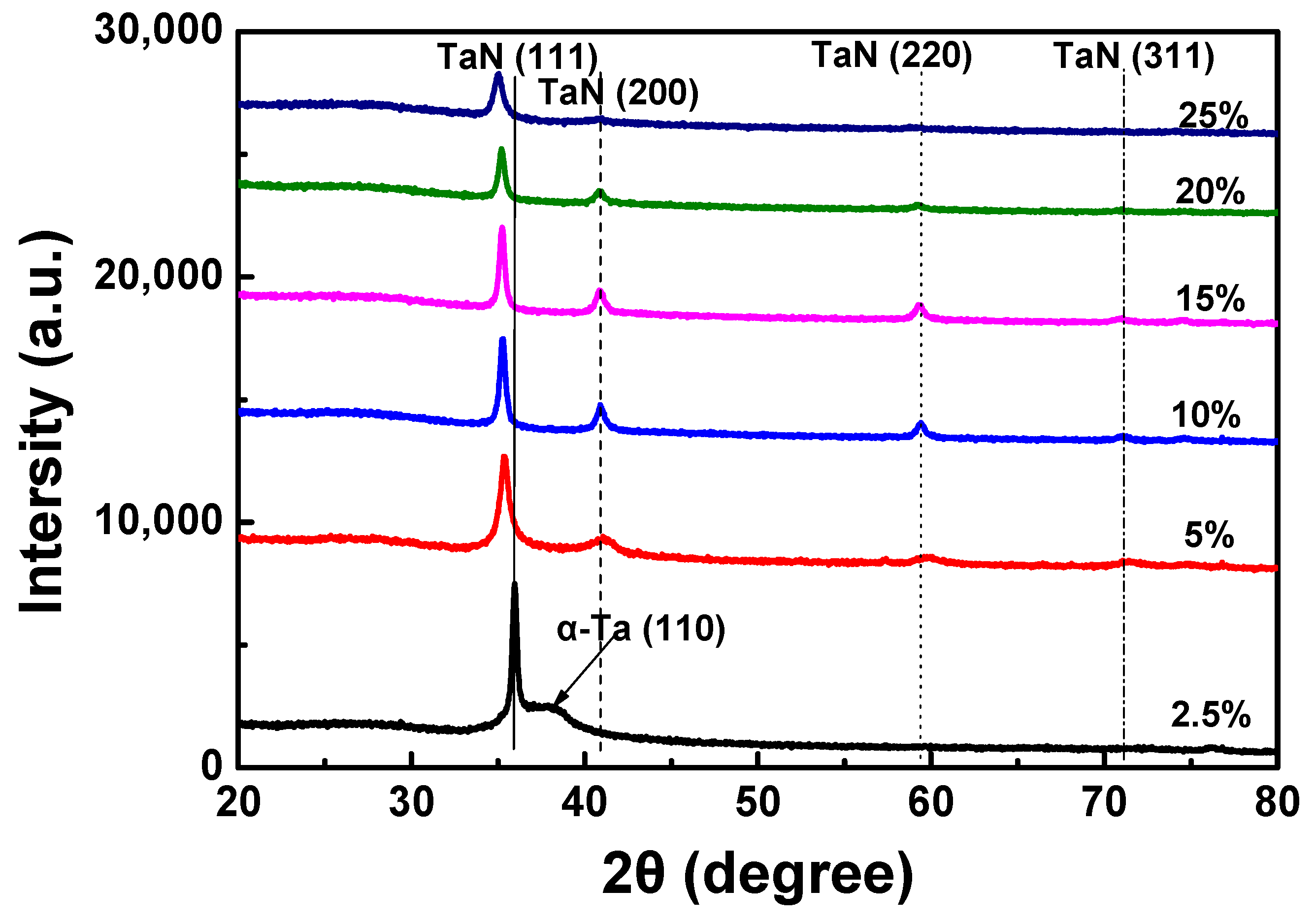
Figure 1 shows the XRD pattern of TaN films with different nitrogen flow ratios and peak positions are list in Table 2. The films are mainly face-centered δ-TaN structure, and the preferred orientation differs depending on the nitrogen flow ratio. When the nitrogen flow ratio is 2.5%, the film is preferentially oriented in the face-centered cubic TaN (111) plane, and a weak α-Ta (110) crystal phase appears. As the nitrogen flow ratio gradually increases, α-Ta (110) crystal phase disappears, the peak intensity of the face-centered cubic TaN (111) surface gradually weakens, and the half-height width gradually increases, indicating that the film begins to change from crystalline to amorphous; with the increase of N2 flow rate, the diffraction peaks shift to a lower degree. This is probably caused by the development of compressive stress [3].
The residual stress is calculated by the sin2Ψ method. According to reference [10], the elastic modulus E = 450 GPa, bulk lattice constant a0 = 0.4353 nm, and the Poisson ratio ν = 0.25 are taken into the equation below:
where σ is the residual inplane stress, ψ is determined from the relationship
and aΨ is obtained for each sample, using the (111) diffraction peaks by Bragg’s equation
and the relationship
for 111 layers. λ = 1.54184 Å for Kα X-ray. Figure 2 shows the plot of σ vs. N2 flow ratio. The residual stress is compressive when N2 flow ratio is 2.5%, and becomes tensile when the ratio increases to 5% and larger.
When the nitrogen flow ratio is 5%, the diffraction peaks in TaN (200), TaN (220) and TaN (311) crystal planes appear in the film, indicating that the film is in a polycrystalline state, mainly with different growth crystal faces. The requirements of the phase change driving force are different, so that the nitrogen flow ratio has a certain relationship with the rapid growth surface of the crystal, thereby affecting the preferred orientation of the film. When the nitrogen flow rate ratio exceeds 20%, the TaN (111) peak is further weakened, and the TaN (200) and TaN (220) crystal faces begin to disappear, indicating that the film is closer to the amorphous state.
3.2. Influence of Nitrogen Flow Ratio on Roughness of TaN Film
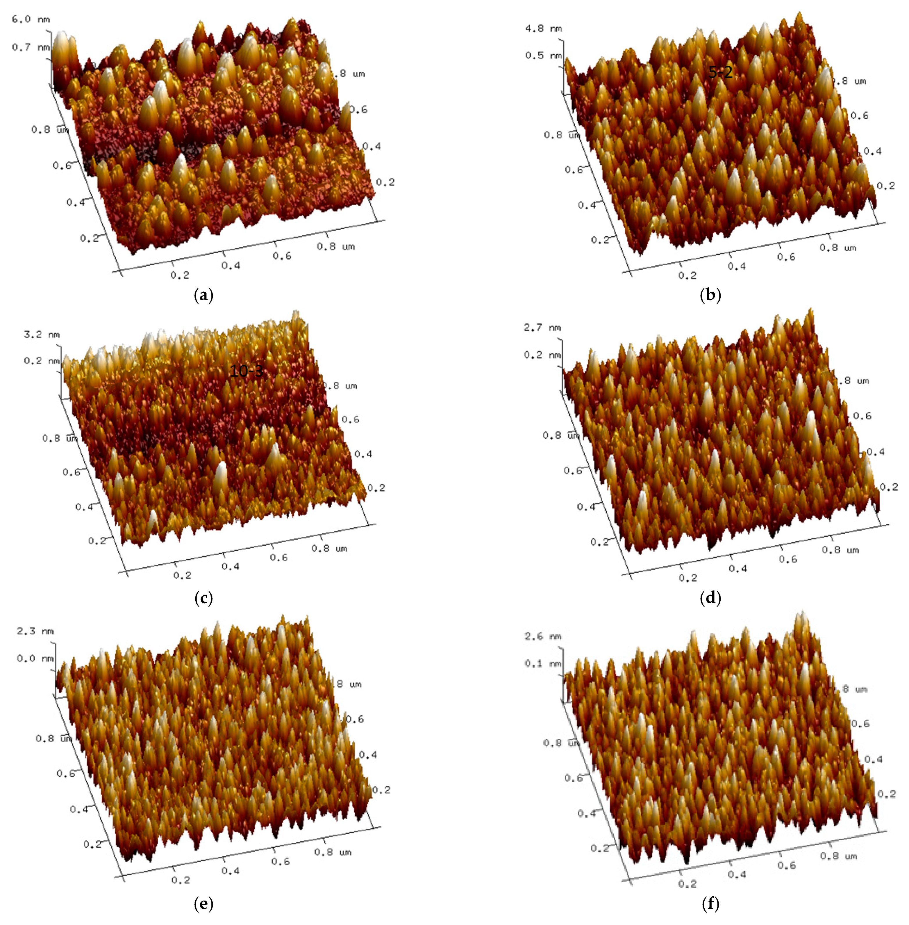
Figure 3 shows AFM photographs of TaN films with different nitrogen flow ratios. When the nitrogen flow rate ratio is 2.5%, the roughness is 1.10 nm; when the nitrogen flow ratio is 5%, the roughness is 1.03 nm; when the nitrogen flow ratio is 10%, the roughness is 0.675 nm; when the nitrogen flow ratio is 15%, the roughness is 0.555 nm; the roughness is 0.507 nm when the nitrogen flow ratio is 20%; and the roughness is 0.581 nm when the nitrogen flow ratio is 25%. It can be seen that as the nitrogen flow ratio increases, the roughness of the film shows a decreasing trend. This result is consistent with the results in the literature [5,11]. When the nitrogen flow ratio is increased to 25%, the roughness of the film is increased. From the topography, when the nitrogen flow rate is 2.5%, the crystal grains are coarse and large clusters appear. As the nitrogen flow ratio increases, the crystal grains gradually refine and homogenize, and the surface of the film becomes smooth, with the appearance of the large clusters. From the aspect of sputtering mechanism, the decrease in film roughness is related to the influence of nitrogen flow ratio. With the increase in nitrogen flow ratio in the sputtering atmosphere, the average free path of particles decreases, and the collision scattering phenomenon is intensified. This gradually reduces the number of particles that move to the surface of the substrates, which react and form films. The sputtering yield also decreases, resulting in a decrease in the deposition rate of the films. Therefore, there is sufficient time for the atoms absorbed on the surface of the thin films to rearrange through surface diffusion, which improves the film density and roughness [12]. On the contrary, when the nitrogen flow rate is relatively low, the deposition rate is large. When the nitrogen flow ratio is further increased to 25%, the roughness of the film is increased, and the target “poisoning” is one of the causes of this phenomenon. The surface of the target produces a rough nanoparticle phenomenon, and can reach the substrate while being embedded in the substrate. Growth into a film leads to an increase in surface roughness [5].
3.3. Effect of Nitrogen Flow Ratio on Deposition Rate of TaN Film
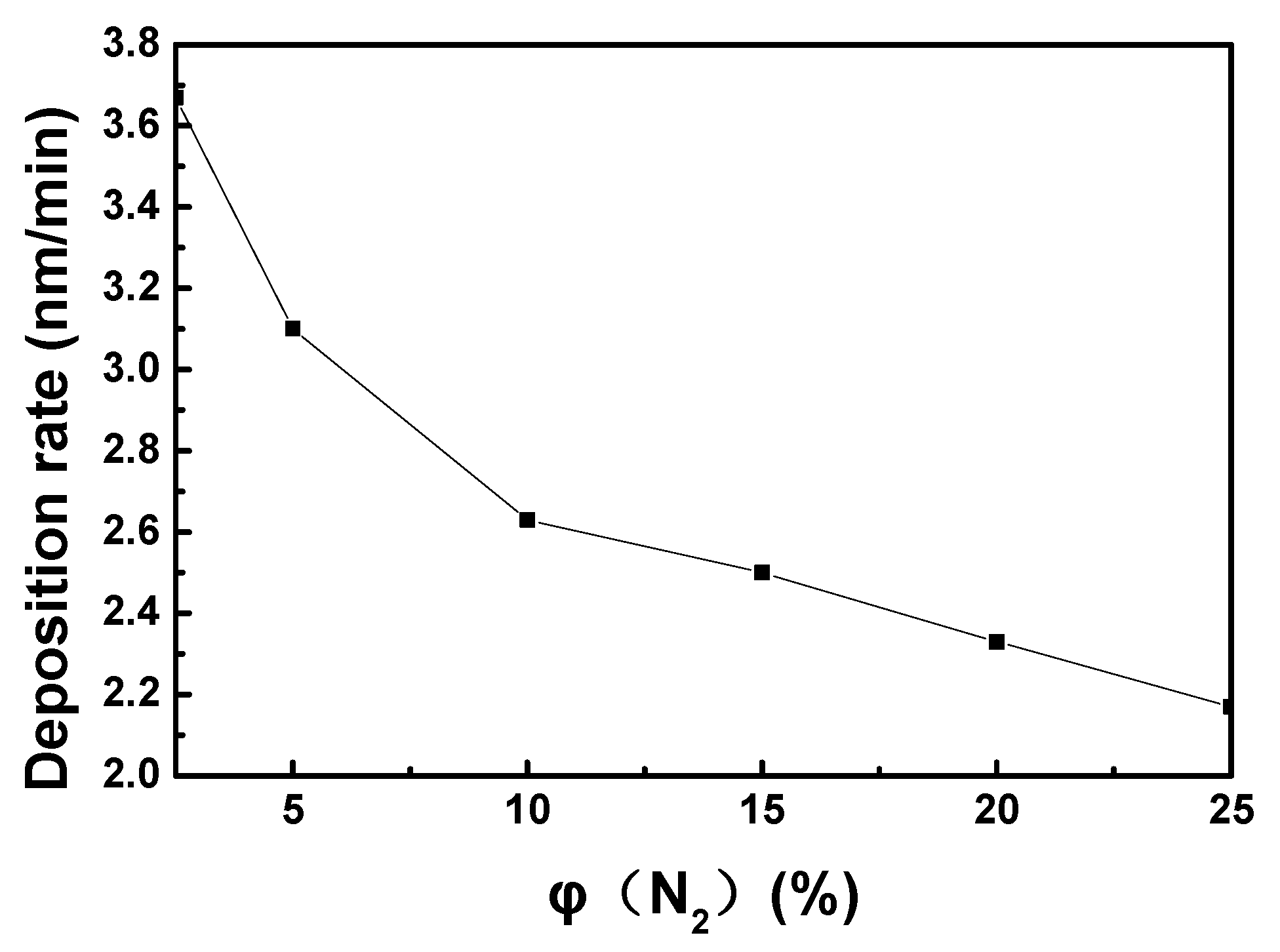
Figure 4 reflects the relationship of the film deposition rate with the N2 flow ratio. It can be seen from picture that the deposition rate of the TaN film gradually decreases with the increase in the N2 flow ratio in the sputtering atmosphere, which is consistent with the results of international peer studies [5]. The film growth is caused by the sputtering atmosphere increases, the mean free path of the particles decreases, the collision scattering phenomenon is intensified, and it is bombarded and flows to the surface of the substrate. The number of particles on the surface of the reaction film is gradually reduced, and the sputtering yield is lowered, resulting in a decrease in the film growth rate. In addition, due to the presence of a large amount of active N atoms in the sputtering atmosphere, as the nitrogen flow rate in the sputtering atmosphere increases, the number of active N atoms in the atmosphere gradually increases. They chemically react with the Ta atoms on the surface of the target and produce TaN compounds, causing the target to become slightly “poisoned” [1,4], and thereby reducing the sputtering rate.
3.4. Influence of Nitrogen Flow Ratio on the Bonding Force of TaN Film Base
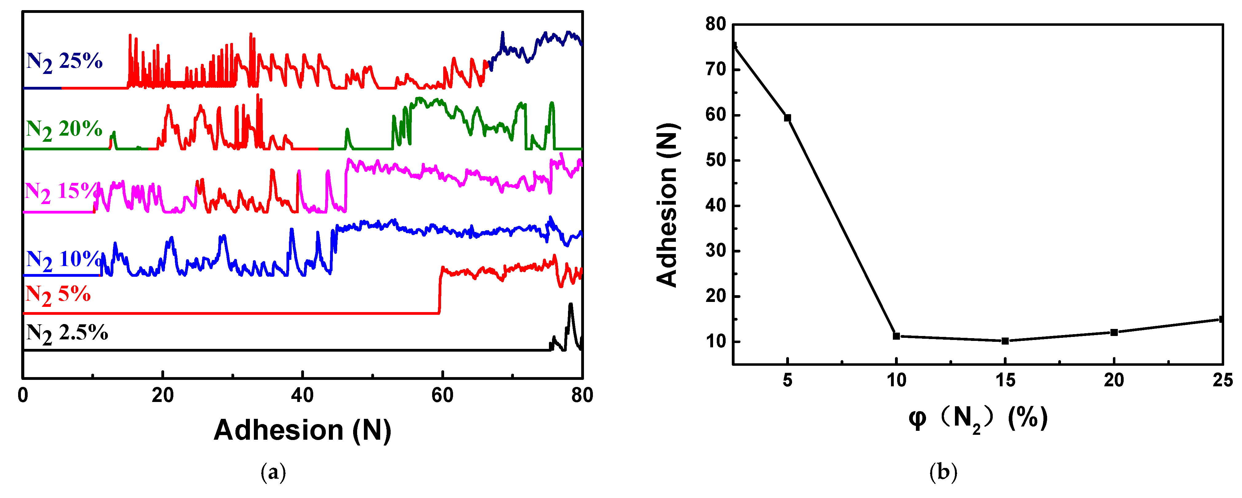
The interface bonding strength between the film and the substrate is one of the most important properties of the film, and is critical to the service life of components in the surface engineering field. The strength of the interface bonding strength directly affects the actual use of the film. In the scratch method, the film-based bonding force is characterized by the minimum pressure of the coating cracking, that is, the critical load, and the critical load is the pressure corresponding to the sudden increase in the acoustic emission signal of the cracking of the coating and the sharp fluctuation. Figure 5 shows the adhesion of TaN films to the Al2O3 ceramic substrate at different nitrogen flow ratios. It can be seen from Figure 4 that the film-based bonding force of the prepared TaN film gradually decreases with the increase in the nitrogen flow ratio. When the nitrogen flow reaches 10% and exceeds 10%, the film-based bonding force tends to be stable and slightly increases. The increasing trend indicates that the nitrogen flow rate has a greater influence on the membrane-based bonding force when the gas pressure remains unchanged. This is mainly due to the fact that the nitrogen flow rate has a large influence on the sputtering, the composition and structure of the film layer, the bonding state of the film layer and the substrate. Before the deposition of the film, the Al2O3 substrate is subjected to plasma bombardment under high bias, and the bombardment can activate the surface of the substrate, thereby facilitating the adhesion between the film and the substrate. When the nitrogen flow rate is low, there are more Ar ions in the vacuum chamber, and the N2 content is relatively small. The deposited particles can obtain a higher rate of kinetic energy under the biasing force to accelerate the impact and deposit on the surface of the substrate. They also have a certain compacting effect on previously deposited particles, which can eliminate internal defects of the coating, thereby obtaining a dense nanocrystalline structure and improving the bonding strength of the coating. As the N2 flow rate increases, the neutral nitride particles in the vacuum chamber gradually increase, and the kinetic energy loss on the sputter ion deposition path is large, resulting in a decrease in the compactness of the coating and a decrease in the film-based bonding force. However, the increase in the nitrogen flow rate ratio leads to a decrease in the argon ion flow sputtering ability, and the target sputtering yield is reduced. To some extent, the target is “poisoned” and the target sputtering is unstable; both effects reduce the density of the film. The bonding force is reduced. The difference in the binding force of the TaN film obtained by magnetron sputtering at different nitrogen flow ratios may also be due to the phase structure change in the film. When the nitrogen flow ratio is low, the TaN film is mainly (111), and the film stress is small. When the nitrogen flow ratio is increased to 5%, the prepared TaN film is TaN (111) and (200) (220) (311). When a plurality of crystal forms coexist, the film stress is large; when the nitrogen flow ratio reaches 10%, the preferred orientation of (200) (220) (311) is more obvious, and the content of the nitride phase of the film is increased. The coating properties dominated, the average residual stress became larger, and the film-based bonding force significantly decreased and reached a minimum. When the nitrogen flow rate ratio exceeds 20%, the crystal structure becomes the (111) preferred orientation, the film stress becomes smaller, and the bonding force increases.
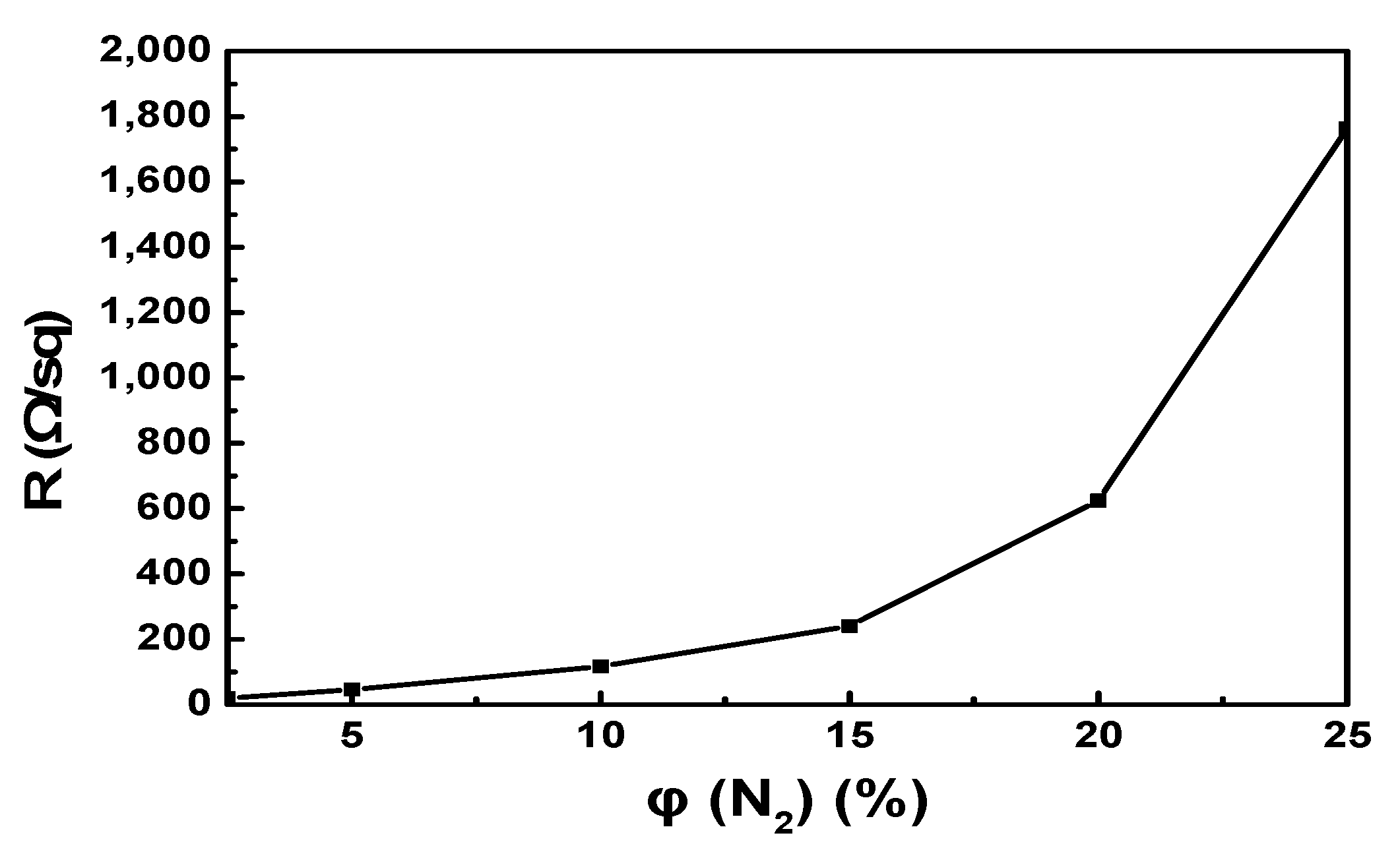
Figure 6 reflects the relationship between the film’s square resistance and the N2 flow ratio. As can be seen in Figure 5, as the N2 flow rate is from 2.5% to 15%, the sheet resistance of the film increases from 23.2 Ω/sq to 240.98 Ω/sq, while the N2 flow ratio ranges from 15% to 25%. The resistance increases from 240.98 Ω/sq to 1764.8 Ω/sq. It can be seen that as the N2 flow ratio increases, the sheet resistance of the film increases. When the N2 flow ratio is higher than 15%, the sheet resistance of the film increases rapidly. This is because the increase in the N2 flow ratio causes the Ta vacancies in the film to increase, and the conductivity type of the film gradually changes from electron conduction to vacancies conduction. Additionally, the density of states near the Fermi level is lowered, resulting in an increase in resistivity. Transition from a metallic state to an insulating state [13]. Some researchers believe that as the N2 flow ratio increases, the sputtering yield decreases, the deposition rate decreases, and the atomic deposition rate is slow, the film structure is relatively loose, and the grain size decreases as the nitrogen flow ratio increases. The trend is to increase the grain boundary and stacking fault in the film; the compactness of the film layer is reduced, and the denseness of the film surface is beneficial to reduce the resistivity [14]. Therefore, as the nitrogen content in the film increases, the sheet resistance increases.
4. Conclusions
- The TaN film is mainly the face-centered δ-TaN structure. The preferred orientation varies with the nitrogen flow ratio. With the increase in the nitrogen flow ratio, the surface roughness of the film first decreases and then increases. When the nitrogen flow ratio is 20%, the surface roughness is at least 0.507 nm.
- The deposition rate of the film decreases with the increase in the N2 flow ratio in the sputtering atmosphere.
- The film-based bonding force of TaN film decreases first, and then increases with the increase in nitrogen flow ratio. When the nitrogen flow ratio is 15%, the film-based bonding force reaches a minimum of 10.2 N.
- The electrical properties of the film are significantly affected by the nitrogen flow ratio, and the sheet resistance value increases with the increase in the nitrogen flow ratio, which can be flexibly controlled by adjusting the nitrogen flow ratio.
Author Contributions
Conceptualization, Z.L. and Y.Z.; formal analysis, Z.L. and Y.Z.; funding acquisition Z.L. and H.Z.; investigation, Z.L., Y.Z. and Y.W.; methodology, Z.L. and Y.Z.; project administration, Z.L. and Y.Z.; resources, Z.L. and Y.Z.; Software, Z.L., Y.Z. and Y.W.; Writing; Writing—review & editing, Z.L., Y.Z. and Y.W.; data curation J.L.; funding acquisition and supervision H.Z. All authors have read and agreed to the published version of the manuscript.
Funding
This work is supported by Scientific Research Fund of Heilongjiang Academy of Sciences (KY2020WL02) and Special program for improving innovation ability in the field of discipline of Heilongjiang Academy of Sciences (XKLY2019WL01-03).
Institutional Review Board Statement
Not applicable.
Informed Consent Statement
Not applicable.
Data Availability Statement
All data included in this study are available upon request by contact with the corresponding author.
Conflicts of Interest
The authors declare no conflict of interest.
References
- Wang, B.; Song, Z.G.; Cao, Q.T. Study on Low TCR TaN Thin Film Resistors by D.C. Magnetron Sputtering. Adv. Mater. Res. 2015, 1082, 34–37. [Google Scholar] [CrossRef]
- Ji, X.; Zhou, X.Y.; Teng, J.Y.; Mi, Y.M.; Zhang, C.M. Mechanical and Corrosion Properties of TaN Coatings by N2/Ar Flow Ratio Processes. Surf. Eng. 2013, 29, 580–583. [Google Scholar] [CrossRef]
- Bernoulli, D.; Müller, U.; Schwarzenberger, M.; Hauert, R.; Spolenak, R. Magnetron Sputter Deposited Tantalum and Tantalum Nitride Thin Films: An Analysis of Phase, Hardness and Composition. Thin Solid Film. 2013, 548, 157–161. [Google Scholar] [CrossRef]
- Chen, S.F.; Wang, S.J.; Yang, T.H.; Yang, Z.D.; Bor, H.Y.; Wei, C.N. Effect of Nitrogen Flow Rate on TaN Diffusion Barrier Layer Deposited Between A Cu Layer and A Si-based Substrate. Ceram. Int. 2017, 43, 12505–12510. [Google Scholar] [CrossRef]
- Firouzabadi, S.S.; Naderi, M.; Dehghani, K.; Mahboubi, F. Effect of Nitrogen Flow Ratio on Nano-Mechanical Properties of Tantalum Nitride Thin Film. J. Alloy. Compd. 2017, 719, 63–70. [Google Scholar] [CrossRef]
- Grosser, M.; Seidel, H.; Schmid, U. Microstructure and Mechanical Properties of Sputter Deposited Tantalum Nitride Thin Films After High Temperature Loading. Thin Solid Film. 2015, 629, 69–78. [Google Scholar] [CrossRef]
- Arshi, N.; Lu, J.; Joo, Y.K.; Yoon, J.H.; Koo, B.H. Effects of Nitrogen Composition on the Resistivity of Reactively Sputtered TaN Thin Films. Surf. Interface Anal. 2015, 47, 154–160. [Google Scholar] [CrossRef]
- Jiang, H.; Wang, C.; Zhang, W.; Si, X.; Li, Y. Influences of Film Thickness on the Electrical Properties of TaNx Thin Films Deposited by Reactive DC Magnetron Sputtering. J. Mater. Sci. Technol. 2010, 26, 597–600. [Google Scholar] [CrossRef]
- Zaman, A.; Meletis, E.I. Microstructure and Mechanical Properties of TaN Thin Films Prepared by Reactive Magnetron Sputtering. Coatings 2017, 7, 209. [Google Scholar] [CrossRef] [Green Version]
- Shin, C.S.; Gall, D.; Kim, Y.W.; Hellgren, N.; Petrov, I.; Greene, J.E. Development of preferred orientation in polycrystalline NaCl-structure δ-TaN layers grown by reactive magnetron sputtering: Role of low-energy ion surface interactions. J. Appl. Phys. 2002, 92, 5084–5093. [Google Scholar] [CrossRef]
- Lee, D.W.; Kim, Y.N.; Cho, M.Y.; Ko, P.J.; Lee, D.; Koo, S.M. Reliability and Characteristics of Magnetron Sputter Deposited Tantalum Nitride for Thin Film Resisters. Thin Solid Film. 2018, 660, 688–694. [Google Scholar] [CrossRef]
- Kumar, M.; Mishra, S.; Mitra, R. Effect of Ar:N2 Ratio on Structure and Properties of Ni-TiN Nanocomposite Thin Films Processed by Reactive RF/DC Magnetron Sputtering. Surf. Coat. Technol. 2013, 228, 100. [Google Scholar] [CrossRef]
- Stampfl, C.; Freeman, A.J. Metallic to Insulating Nature of TaNx: Role of Ta and N Vacancies. Phys. Rev. B 2003, 064108, 67–75. [Google Scholar]
- Ruan, J.L.; Huang, J.L.; Chen, J.S.; Lii, D.F. Effects of Substrate Biason the Reactive Sputtered Zr-Al-N Diffusion Barrier Films. Surf. Coat. Technol. 2005, 200, 1652–1658. [Google Scholar] [CrossRef]
Figure 1.
XRD pattern of TaN films with different nitrogen flow ratios.

Figure 2.
Plot of σ vs. N2 flow ratio.

Figure 3.
AFM images of TaN films with different nitrogen flow ratios: (a) 2.5%, (b) 5%, (c) 10%, (d) 15%, (e) 20%, (f) 25%.
Figure 3.
AFM images of TaN films with different nitrogen flow ratios: (a) 2.5%, (b) 5%, (c) 10%, (d) 15%, (e) 20%, (f) 25%.

Figure 4.
Relationship between nitrogen flow ratio and film deposition rate.

Figure 5.
Different nitrogen flow ratios of TaN film on Al2O3 ceramic substrate (a) Relationship between film-based bonding force and acoustic emission under different nitrogen flow rates, (b) Relationship between nitrogen flow rate and film-based bonding force.
Figure 5.
Different nitrogen flow ratios of TaN film on Al2O3 ceramic substrate (a) Relationship between film-based bonding force and acoustic emission under different nitrogen flow rates, (b) Relationship between nitrogen flow rate and film-based bonding force.

Figure 6.
Relationship between nitrogen flow ratio and sheet resistance.


Table 1.
Synthesis Conditions of TaN Films.
| Experiment | Film Thickness (nm) | Flow Ratio (%) | Roughness (nm) | Crystallite/Grain Sizes (nm) | Adhesion Force (N) |
|---|---|---|---|---|---|
| 1 | 220.20 | 2.5 | 1.10 | 0.48 | 75.40 |
| 2 | 186.00 | 5 | 1.03 | 0.24 | 59.40 |
| 3 | 157.80 | 10 | 0.68 | 0.36 | 11.25 |
| 4 | 150.00 | 15 | 0.56 | 0.36 | 10.20 |
| 5 | 139.80 | 20 | 0.51 | 0.36 | 12.10 |
| 6 | 130.20 | 25 | 0.58 | 0.24 | 15.00 |
Table 2.
XRD Peak Positions of TaN Films.
| Flow Ratio/% | TaN (111) | α-Ta (110) | TaN (200) | TaN (220) | TaN (311) |
|---|---|---|---|---|---|
| 2.5 | 35.96° | 38.09° | - | - | - |
| 5 | 35.35° | - | 41.16° | 59.75° | 71.41° |
| 10 | 35.28° | - | 40.90° | 59.41° | 70.99° |
| 15 | 35.25° | - | 40.90° | 59.36° | 70.89° |
| 20 | 35.20° | - | 40.87° | 59.23° | - |
| 25 | 35.04° | - | - | - | - |
(-: too weak to be recognized).
Publisher’s Note: MDPI stays neutral with regard to jurisdictional claims in published maps and institutional affiliations. |
© 2021 by the authors. Licensee MDPI, Basel, Switzerland. This article is an open access article distributed under the terms and conditions of the Creative Commons Attribution (CC BY) license (https://creativecommons.org/licenses/by/4.0/).
Share and Cite
MDPI and ACS Style
Li, Z.; Zhang, Y.; Wang, Y.; Li, J.; Zhao, H. Effect of Nitrogen Flow Ratio on Degradation Behaviors and Failure of Magnetron Sputter Deposited Tantalum Nitride. Coatings 2021, 11, 1133. https://doi.org/10.3390/coatings11091133
AMA Style
Li Z, Zhang Y, Wang Y, Li J, Zhao H. Effect of Nitrogen Flow Ratio on Degradation Behaviors and Failure of Magnetron Sputter Deposited Tantalum Nitride. Coatings. 2021; 11(9):1133. https://doi.org/10.3390/coatings11091133
Chicago/Turabian StyleLi, Zhigang, Yubao Zhang, Yi Wang, Jinfeng Li, and Hongtao Zhao. 2021. "Effect of Nitrogen Flow Ratio on Degradation Behaviors and Failure of Magnetron Sputter Deposited Tantalum Nitride" Coatings 11, no. 9: 1133. https://doi.org/10.3390/coatings11091133
Note that from the first issue of 2016, this journal uses article numbers instead of page numbers. See further details here.