
Abstract
Thermal neutron (∼25 meV) beam is a powerful tool for investigating the structure and properties of materials used in science and technology. A laser-driven neutron source generating 1010 neutrons within 1 ns duration is utilized to a single shot radiography with a dual beam of thermal neutrons and X-rays. As a proof of principle, we show the non-destructive inspection of hazardous substances (Cadmium) contained in a typical battery, when the cadmium anode thickness is evaluated from the transmittance of thermal neutrons. The fact that the neutron inspection above is performed with a single laser shot, i.e. with a single bunch of neutrons leads to a safer neutron source that is optically controlled on/off, and provides a novel tool for science and engineering.
Export citation and abstract BibTeX RIS

Content from this work may be used under the terms of the Creative Commons Attribution 4.0 license. Any further distribution of this work must maintain attribution to the author(s) and the title of the work, journal citation and DOI.
Neutron beams provide indispensable insight into the structure and properties of materials studied in biology, chemistry, medicine, physics, and engineering. Currently, nuclear reactors and spallation neutron facilities are providing neutron sources for scientific and industrial applications. Furthremore, compact accelerator-based neutron sources are successfully applied to neutron analysis. Especially, thermal neutrons (26 meV) are utilized as a powerful tool for the non-destructive inspection due to their large nuclear reaction cross sections for specific species including hydrogen. 1)
Laser-driven neutron sources (LDNSs) are also attracting interest because of their specific characteristics: (i) the compactness of the source in the range of a few millimeters and (ii) the capability of generating short bursts of neutron bunches with time durations approaching a sub-ns at the source, and (iii) the multi-beam generation with x-rays and ions. Several groups have started developing LDNSs all over the world. 2–18) Roth et al. 4) demonstrated radiography imaging using fast neutrons (keV–MeV) generated from LDNS, and some groups 19–21) also measured fast neutron images. Because the neutron capture cross section generally increases with decreasing neutron energies and there are resonance absorptions in the energy region of eV, low-energy neutron generation has been explored. Recently, low-energy neutrons were generated by LDNSs combined with moderators to generate epi-thermal (0.5–100 keV), 22)) thermal, 23) and cold (∼1 meV) 24)) neutrons.
In this letter, we show the development of LDNS generating high yield of fast neutrons (1010) within a short bunch duration (∼1 ns) from a fingertip-size source (∼1 cm3). The peak neutron density reaches 1019 n s−1 cm−3, which is higher than those of stellar environments seen in Red Giant Stars 14,25) in Universe. Furthermore, the source generates bright x-rays simultaneously with neutrons. We developed a moderation system to decelerate fast neutrons down to thermal region and extract them into air, and demonstrate, as a proof of principle, a non-destructive inspection of hazardous substances contained in a typical battery using thermal neutrons and x-rays generated by a single laser shot. We obtained the image of a nickel–cadmium (Ni–Cd) battery and evaluated the Cd content from the neutron transmittance. We simultaneously record an X-ray image of the same samples with another imaging system, and discuss the characteristic of the thermal neutron images compared to the X-ray image. The inspection above was performed with a single laser shot, i.e. a single bunch of neutron beam, allowing us to take a "snap shot" of objects with thermal neutrons, which provides an indispensable tool for science and engineering.
Schematics of our LDNS setup is shown in Fig. 1. The neutron source is located at the center of the blue circle in Fig. 1(a). A high-intensity (∼5 × 10¹⁸ W cm−2) laser with a pulse duration of 1.5 ps from the LFEX laser system 26) is focused onto a foil of deuterated polystyrene (CD) with a thickness of 1.5–5 μm. This CD foil serves as an ion source and subsequently accelerates the ions up to MeV energies. As discussed in Refs. 27–30, the ion acceleration is boosted by a nonlinear heating mechanism characteristic of laser-plasma interactions in ps time scales. This mechanism also enhance the maximum energies and the yields of the accelerated ions. The accelerated ions then bombarded on a beryllium (Be) block converter installed behind the CD foil to generate neutrons. Deuterons and protons are accelerated from CD and contaminants on the surface of the foil such as water, respectively. Subsequently, the neutrons are generated via nuclear reactions on 9Be, including the 9Be(p, n)9B and 9Be(d, xn) reactions.

Fig. 1. (Color online) A setup of laser-driven neutron source at Osaka University. As seen in the inset entitled "Neutron source," a high-intensity laser is focused onto a foil of deuterated polystyrene (CD), which accelerates deuterons up to MeV energies. The deuterons generate neutrons via nuclear reactions on the Be block. Several kinds of diagnostic instruments are surrounding the neutron source: (i) the Thomson parabola (TP) ion spectrometer at 0°, (ii) the stacked CR-39 plates for neutron detection at 94°, and (iii) the time-of-flight neutron detector at 12°. A setup for neutron image detection (radiography package) is installed at 18°.
Download figure:
Standard image High-resolution imageWe simultaneously measure the energy spectra of the laser-driven ions and neutrons. The accelerated ions are analyzed by a Thomson parabola (TP) spectrometer 31) through a pinhole of 0.5 mm diameter through the Be converter, as shown in Fig. 1(c). The energy spectra of the neutrons are measured by a time-of-flight (TOF) detector 32) located 12° direction away from the laser axis with 8.3 m distance out of the vacuum chamber. The ToF detector was calibrated with (n, 2n) nuclear reactions. 14) The neutron energy spectrum shows a broad spread having the maximum energy of up to 20 MeV [see Fig. 2(b)]. This maximum energy is almost identical with that of the primary protons [see Fig. 2(a)]. In addition, the temperatures evaluated from the slopes are in agreement between the neutrons and the protons. These are attributed to the kinetic energy transfer from a proton to a neutron in (p, n) reactions. The neutron energy spectrum can be consistently explained by nuclear reactions with laser-driven ions.

Fig. 2. (Color online) Simultaneous energy measurements of laser-driven ions (a) and neutrons (b), under the irradiation of 7.9 × 10¹⁸ W cm−2, 800 J, 1.5 ps laser pulse (shot no. L3661). The maximum energy and characteristic temperature of protons are in agreements with those of neutrons. The neutron yield of 1.1 × 10¹⁰ neutrons/sr is recorded by the CR-39, assuming the detection efficiency of 1.0 × 10⁻⁴.
Download figure:
Standard image High-resolution imageThe fast neutrons are moderated by a 10 cm thick polyethylene block installed with 19 cm distance from the LDNS inside the radiography package [Fig. 1(d)]. Figure 3(a) shows the spectrum of the moderated neutrons in a unit of cm2 at the moderator face calculated by the PHITS simulation code, 33) where fast neutrons from the LDNS become thermal equilibrium with the room temperature (∼26 meV). As an imaging device, we adopt an indirect (or transfer) imaging method with a dysprosium (Dy) plate. 34,35) The Dy plate (50 mm square and 0.25 mm thickness) was installed just behind the samples. After the laser shot, the Dy plate was placed on a position on an imaging plate (IP) with a shield and subsequently the IP record the radiations from the Dy plate for 2 h. The natural Dy includes an isotope 164Dy with a natural isotopic abundance of 28.18%, which has relatively large thermal neutron capture reaction cross section of 2650 barn as shown in Fig. 3(a). This cross section are larger than those of typical materials by a few orders of magnitude. Because the neutron-capture cross section of 164Dy drastically decreases above 1 eV [see Fig. 3(a)], Dy is sensitive mainly to thermal neutrons. When Dy is irradiated with low energy neutrons, neutrons are effectively captured on 164Dy and an unstable isotope 165Dy is generated by the 164Dy(n, γ)165Dy reaction. The unstable isotope 165Dy β-decays through emission of an electron with a half-life of 2.234 h. The IP is more sensitive to charged particles such as electrons rather than neutron and γ-rays. Thus, the present method is effective for visualizing thermal neutron profiles free from background radiations including higher-energy neutrons and x-rays. We simultaneously obtain a complementary X-ray image recorded by another IP installed behind the Dy plate during the laser shot. In this case the IP was removed from the sample position immediately after the laser shot and analyzed to reduce the detection of beta-rays emitted from the Dy.
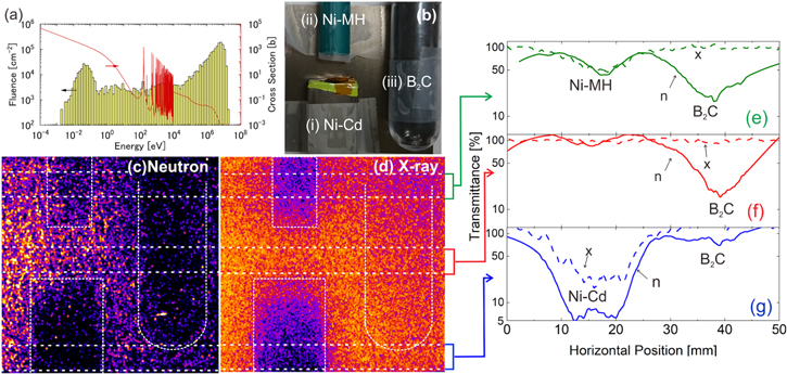
Fig. 3. (Color online) (a) The energy spectrum of moderated neutrons (bars) calculated by PHITS 33) and the neutron absorption cross section of 164Dy (line). (b) The picture of samples. (c), (d) Radiographic images of (i) a nickel–cadmium (Ni–Cd) battery, (ii) a nickel-metal hydride battery, and (iii) boron carbide (B2C) powder in a plastic test tube obtained with neutrons (c) and x-rays (d). (e)–(g) The transmittance of neutrons (solid) and x-rays (dashed) along the horizontal lines indicated in green, red and blue belts, respectively, seen in (c), (d). The results (c) and (d) were obtained simultaneously with a single laser shot (6 × 10¹⁸ W cm−2, shot no. L2843). We used a Be block without pinhole, unlike the one shown in Fig. 1.
Download figure:
Standard image High-resolution imageWe demonstrate that our LDNS has practically high enough neutron fluence to perform a radiography imaging in a single laser shot. We installed several samples in contact with the moderator: (i) a nickel–cadmium (Ni–Cd) battery (SANYO, Cadnica 3KF-B650), (ii) a nickel-metal hydride (Ni-MH) Cd free battery, and (iii) boron carbide (B2C) powder in a plastic tube of 10 mm inner diameter [see Fig. 3(b)]. In the neutron image as shown in Fig. 3(c), the shadows of the Ni–Cd battery and the B2C powder were observed clearer in the neutron image compared to that of the Ni-MH battery. Because stable isotope 113Cd has a large thermal neutron capture cross section of 20 647 barn, the neutron transmittance for the Ni–Cd battery [the solid line at x = 10–20 mm in Fig. 3(g)] is approximately 10 times lower than that of Ni-MH [the solid line at x = 10–20 mm Fig. 3(e)]. Hence, we can distinguish which battery includes Cd. Another low transmittance is seen for the B2C sample [the solid lines at x = 30–50 mm in Figs. 3(e), 3(f)]. In general, B2C is used as a neutron absorber because of the large neutron reaction cross section on 10B in low energy. In contrast, in the image of the x-rays [see Fig. 3(d)], B2C shows the high transmittance [the dashed lines at x = 30–50 mm in Figs. 4(e), 4(f)], because of the low sensitivity of x-rays to low-atomic number materials of boron and carbon. This result highlights the advantage that neutrons can diagnose the materials that are transparent for x-rays.

Fig. 4. (Color online) (a) The image of neutron transmittance simulated for a model of Ni–Cd battery shown in the frame (b). (c) The energy of incident (dashed) and transmitted (solid) neutrons in the simulation. (d) The simulated transmittance along the x axis (dashed line) assuming the Cd thickness of 0.76 mm as the total thickness of 4 anodes. The experimental result (solid line) is taken from Fig. 3(g).
Download figure:
Standard image High-resolution image
The spatial resolution of the neutron image is around 5 mm, which is attributed to the laminarity of neutrons from the moderator. The spatial resolution becomes low when we use moderators. However, we can improve it by installing a honeycomb-shape neutron collimator 36) between the sample and moderator.
The thickness of the Cd anode is nondestructively evaluated from the neutron transmittance obtained in our radiography. Figure 4(a) shows the neutron transmittance calculated with the PHITS code 33) for the battery including four Cd anodes as shown in Fig. 4(b). In this calculation, we take the neutron energy spectrum as shown in Fig. 3(a) as the input. It is revealed that the low transmittance of 5% shown in Fig. 3(g) is consistent with the absorption by Cd plates with a total thickness of 0.76 mm [see Fig. 4(d)]; this evaluated thickness is in agreement with the value of 0.76 ± 0.31 mm, derived from the data sheet. 37)
In the present experiment, the density of the thermal neutrons is evaluated to be ∼104 cm−2 per a pulse on the sample, corresponding to ∼1010 neutrons in 4π at the source. Nowadays, a single laser shot of several LDNSs 4,11–14) can achieve the yields of approximately 1010 for fast neutrons, indicating that the present scheme of radiography is applicable to these LDNSs.
It is worth noting that the radiography images are obtained only using a single pulse of neutrons. The duration of the neutron bunch is still only in a few tens of μs after the moderation. In general, temporal resolution of 0.1–1 ms is required for measurements of hydrodynamic phenomena including fuel injection in engines, 38) void generation in water pipes 39) and vapor bubble collapse in fast jet. 40) The present result indicates that LDNSs can be utilized to visualize these high-speed phenomena, combined with a high repetition-rate power laser system. 41,42)
Acknowledgments
This work was funded by Grant-in-Aid for Scientific Research (25420911, 26 246 043) of MEXT, A-STEP (AS2721002c) and PRESTO (JPMJPR15PD) commissioned by JST, and partially supported by JSPS Bilateral Program (Grant No. JSPSBP120209922). The authors thank the technical support staff of ILE for their assistance with the laser operation, target fabrication and plasma diagnostics. This work was supported by the Collaboration Research Program of ILE, Osaka University. AY gratefully appreciates suggestions from Prof. Oda of Kobe University on the CR39 calibration. AY also appreciates fruitful discussions with the members of the committee on "Laser-driven Neutron Source" organized by the Laser Society of Japan, and a consultancy meeting on "Advances in Laser-driven Neutron and X-ray Sources" commissioned by IAEA. SK acknowledge funding from EPSRC, UK (No. EP/J002550/1-Career Acceleration Fellowship held by S.K. and No EP/K022415/1), and STFC, UK (No. ST/P000142/1).
Data availability
The data that support the findings of this study are available from the corresponding author upon reasonable request.