A Cost-Effective Photonic Radar Under Adverse Weather Conditions for Autonomous Vehicles by Incorporating a Frequency-Modulated Direct Detection Scheme
 Abhishek Sharma1*
  Sushank Chaudhary2*
  Jyoteesh Malhotra3
  Muhammad Saadi4 Sattam Al Otaibi5
  Jamel Nebhen6 Lunchakorn Wuttisittikulkij2*
- 1Department of Electronics Technology, Guru Nanak Dev University, Amritsar, India
- 2Wireless Communication Ecosystem Research Unit, Department of Electrical Engineering, Chulalongkorn University, Bangkok, Thailand
- 3Department of Electronics and Communication Engineering, Regional Campus-Guru Nanak Dev University, Jalandhar, India
- 4Department of Electrical Engineering, University of Central Punjab, Lahore, Pakistan
- 5Department of Electrical Engineering, College of Engineering, Taif University, Taif, Saudi Arabia
- 6Prince Sattam bin Abdulaziz University, College of Computer Engineering and Sciences, Alkharj, Saudi Arabia
In recent years, there have been plenty of demands and growth in the autonomous vehicle industry, and thus, challenges of designing highly efficient photonic radars that can detect and range any target with the resolution of a few centimeters have been encountered. The existing radar technology is unable to meet such requirements due to limitations on available bandwidth. Another issue is to consider strong attenuation while working under diverse atmospheric conditions at higher frequencies. The proposed model of photonic radar is developed considering these requirements and challenges using the frequency-modulated direct detection technique and considering a free-space range of 750 m. The result depicts improved range detection in terms of received power and an acceptable signal-to-noise ratio and range under adverse climatic situations.
Introduction
The photonic radar, also known as LiDAR (light detection and ranging), has been recognized for its use in multifarious spaces—be it a smart self-governing transport system, topography sensors, remote sensing, landscape ecosystem, flood monitoring, militia surveillance, wireless confined localizing scheme, biomass survey, and under water instabilities [1–4]. The existing and established navigation schemes remain limited toward insignificant precision scope that may result in conveying unpredictable performance, especially in the metropolitan zone, thus ruling out the possibility of their applications in self-driving vehicles mostly known as autonomous vehicles (AVs) [5, 6]. The current demand of the automotive industry is to afford high-range and finer resolution-based radar systems that can trace and distinguish mobile or immobile objects with great meticulousness in any atmospheric circumstance. Nowadays, self-driving vehicles are equipped with contemporary equipment to support the driver, namely, 3-D cameras, microwave radars, GPS systems, and signal processing units, at a very high cost yet offers an inadequate discernibility range of a few meters. In addition to it, self-driving demands high-security requirements for unwanted and mutually affirmative dimensions. This becomes problematic to realize meticulous dimensions under severe atmospheric instabilities. Most of these functions in AVs are reliant upon the radar that can provide precise range detection and visibility with high image perseverance, particularly amid 100–500 m distance. Another factor to be considered is limited power availability in autonomous vehicles, and thus, power requirement should be minimally possible [7]. Keeping in view the different utilities and requirements of the self-driving features, the photonic radar upturns a significant alternative to a traditional radar and has been gaining popularity since its early stage from researchers and AV manufacturers worldwide. The photonic radar delivers finer range resolution and high image resolution compared to the traditional radar with high precision [8–10]. Generally, a low-power continuous wave (CW) laser along with moderately extended reflection interval is engaged to design LiDAR having adequate precision as well as perseverance [11–13]. Triangular sweep is preferred in high-speed target detection because it offers smaller sweep time than the pulsed sweep [13]. Along with it, a frequency-modulated RF signal with a saw-tooth (triangular) modulation function is established to determine the object range and velocity [14]. Besides this, the developed FM-modulated photonic radars are engaged in direct detection formation with an advantage of more sensitivity to the echoes on the expense of a shorter detection range. An alternative protuberant solution is heterodyning mixing which is also known as coherent detection with advantages of high receiver sensitivity, longer ranges, and minimal signal fading than direct detection at the expense of scheme complexity [15, 16]. Figure 1 shows the representation of a photonic radar–equipped vehicle to detect stationary targets.
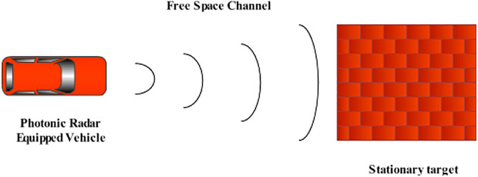
FIGURE 1. Vehicle to stationary target (vehicle) scenario.
Besides challenges in designing a transceiver, the signal must be broadcasted using an extra high–frequency (EHF) band more commonly called the millimeter band (mm band) as RF poses a limit of a small range of few miles as well as incompetence to breach through solid materials [17]. In addition to it, the millimeter band can provide adept spectrum exploitation besides protected communication by allowing supplementary compactly packed waveforms. During transmission through an atmospheric channel, RF signal endures 6 dB variance in attenuation for each octave variation in occurrence. On the contrary, circumstances turn out to be complex once the mm-band signal travels through these atmospheric channels under hostile climatic conditions. These high-frequency signals of the mm-band experience high attenuation under various atmospheric influences, for example, air temperature, air compression and dampness, immersion particles as well as dust, and other atmospheric elements [18]. This again puts hindrance in realizing the elongated target detection–centered use and limits operation to a shorter range. For existing equipment, the absorption peaks transpire at 24 and 60 GHz which is rather high, and providentially, some broadcast openings are available for securing transmission of signals between these peaks. Furthermore, the mm-band–based radar signal has a substantial effect of precipitation attenuation due to scintillation, foliage blockage, rainfall, scattering, and diffraction. Generally, in a mm band, the wavelengths become shorter; thus, mellow echoes are received that result in feeble signal response.
Nevertheless, still in its early stages, some substantial work reported on AVs has been discussed here. An impact of smoulder and dirt particles in air over the operations of self-driving vehicles is described [19]. Another target simulation was developed under unsystematic atmospheric circumstances exploiting electro-optical LiDAR with irregular visibility variances [20]. A comprehensive study of the photonic radar [21] is demonstrated at 950 and 1550 nm. The effect of atmospheric gases has been premeditated to comprehend turbulences due to low ambient temperature [22]. The impact of various fog conditions and experimental evaluation of the working of LiDAR is studied via exhausting foggy conditions in a vacuum chamber [23]. Consequently, the reported work consents the impact of various attenuations due to atmospheric conditions upon the operational efficiency of the photonic radar particularly at high frequency. However, there are limited studies considering the waning effects of atmospheric channels such as rain, haze, and fog that confirm the efficacy of the frequency-modulated continuous wave (FMCW)–driven photonic radar system.
The frequency stands another measure aspect to be considered while designing photonic radars. A laser operates in a 24 GHz band more commonly known as the ISM (industrial, scientific, and medical) band with an unlicensed narrow band (NB) bandwidth of 250 MHz (24–24.5 GHz) and includes a bandwidth of 5 GHz known as ultra-wideband (UWB). While the NB-ISM band is used for detecting blind spots, UWB-ISM is used for higher resolution. As per the new regulation, UWB will be phased out soon, and hence, the ISM band may not be attractive for AV applications. The traditional radar operates in a 70 GHz band, and 70–77 GHz is available for vehicular applications. The 77–81 GHz (with 4 GHz bandwidth) band is known as the short-range radar (SRR) band. The key benefit offered is highly allowed equivalent isotopic radiated power (EIRP) which enables adaptive cruise control [24]. The range resolution offered at 77 GHz with frequency using 4 GHz bandwidth is 4 cm compared to range resolution of 75 cm offered at 24 GHz with the bandwidth of 250 MHz. For simplicity of operation, we have used the linear frequency-modulated continuous-wave radar system using direct detection configuration (FMCW–DD). In a FMCW-DD scheme, a transmitted pulse is intensity modulated by a LFM chirp, and de-chirping is accomplished by comprehensible mixing with a modulated local oscillator (LO) [25, 26].
Based on these facts, authors intend to apply the FMCW-based photonic radar at 77 GHz to detect the range as well as range frequency of a stationary target using a computer-based simulation model and test the simulation model under the influence of varied atmospheric conditions to attain the elongated target range with an adequate SNR (signal-to-noise ratio). The article is organized as follows: The Introduction section explains the necessities, concerns, and contemporary advancements in the field of photonic radars and self-driving vehicles. The Working Principle section elaborates the working principle of the proposed system. The System Description section explains modeling of the proposed system besides comprehensive constraints used in simulation. The Results and Discussion section presents the correlated results of the theory in addition to simulation of the modeled photonic radar and tests the system under adverse weather, and the presented work is concluded in the Conclusion section.
Working Principle
The schematic of the proposed FMCW-based photonic radar is shown in Figure 2 under direct detection configuration which is also known as noncoherent detection. The start frequency of 77 GHz with the sweep bandwidth of 600 MHz is generated using a radio frequency–linear frequency modulator (RF-LFM) driven by a pseudo random sequence generator in conjunction with the saw-tooth modulation function. The carrier signal is generated using a continuous-wave laser light source which is then fed to a dual-arm lithium-niobate (Li-Nb) Mach–Zhander interferometer (MZI) external modulator along with the RF-LFM signal. A D.C. bias generator is used with the modulator to generate second-order sidebands along with the suppression of supplementary bands.
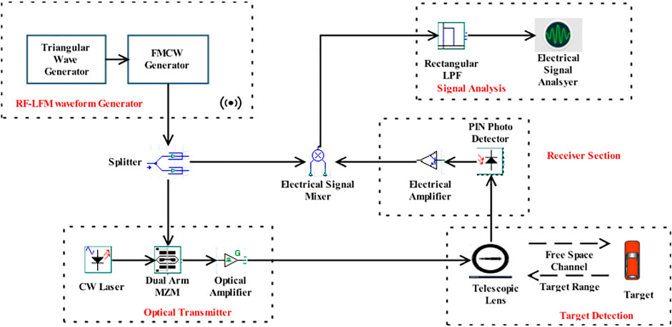
FIGURE 2. Proposed FMCW photonic radar for autonomous vehicles.
The output-modulated signal from MZM depends upon the operating point, that is, if it operates in a quadrature or at a null point [25, 27]. This RF-LFM signal modulated with light is then transmitted over the free-space optics (FSO) network. The FSO channel is expected to assess the efficiency of the proposed scheme under the impact of atmospheric fluctuations as their impact upsurges with an increase in the operating frequency [17, 18, 28]. The resonance signal replicated from the irradiated target is accepted with a transmission delay time given by (
The received signal is then fed to a photo detector to obtain the required electrical signal from the optical signal. Furthermore, this electrical signal is amplified and mixed with reference to the signal received from the LFM generator and fed to a low-pass filter with a cut-off frequency of 1 GHz. The filtered signal is analyzed using an RF spectrum analyzer. The proposed system is modeled and simulated using Optisysem™ while the target model is designed using MATLAB™.
System Description
The proposed photonic radar is modeled using the FMCW direct detection technique as illustrated in Figure 2 to evaluate the distance of an immobile object in the fluctuating weather situations. The radar-armed automobile estimates the range between itself and the immobile target and updates the vehicle accordingly. Unlike the pulsed radar, the FMCW radar is favored due to its cost-effectiveness, small size, and its minimal input power requirement. Complete significant parameters are listed in Table 1.
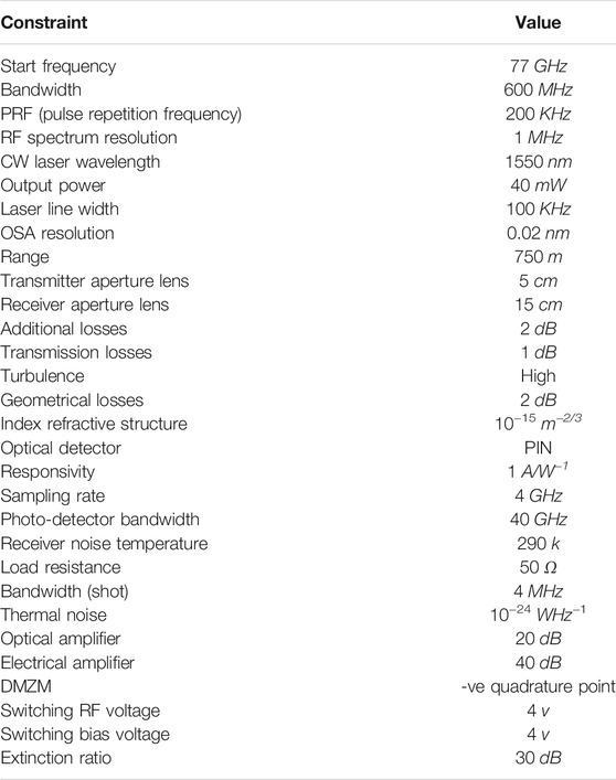
TABLE 1. System parameter.
As shown in Figure 2, the RF-LFM waveform generator is used to generate 77 GHz of the FMCW signal. Frequency variance is measured via a trilateral sweep for approximating the target distance as well as for evaluating the interval time amid the transmitted signal and received echo. Considering that fc is the carrier frequency, Tm is the sweep time, B is the bandwidth, and R is the distance between the target and radar-equipped vehicle, the range frequency fr is given by [29]
A larger quality parameter (Q-factor) of the RF-LFM modulator is achieved by matching the trip time of the local oscillator and the sweep rate of frequency [30]. The transfer function of the modulator is given in Eq. 2 as [31–33]
where Eout and Ein are the input and output optical fields, vπ is the voltage required to change the optical power transfer function [32], ∅i is the initial phase, and S(t) is the RF-LFM signal power that can be expressed as [32]
where fc is the start frequency, B is the sweep bandwidth, and Ac is the amplitude of the LFM signal. For direct detection schemes, MZI modulator output power is stated as [32]
where β is the modulation index (β <<1), ωo is the angular frequency of the transmitted signal, and θo(t) is the random-phase component. Sweep bandwidth B of the system is 600 MHz.
The output-modulated signal is focused on the target via a free-space channel using a transmitting and receiving telescope lens with corresponding aperture sizes of 5 and 15 cm. This free-space network is demonstrated via MATLAB™ to spot the immobile object. Several factors, specifically angular dispersion, atmospheric transmission, and target reflectivity, affect the echo signal from the target at the receiver section. The received power of the echo signal Pr is calculated as [29]
where D is the receiver aperture diameter, ρt is the target reflectivity, At is the target area, τopt is the transmission loss in the optical domain, τatm is the atmospheric loss factor, Aill is the illuminated area at the target, and R is the target range. The echoed signal power Eref at the receiver is given as [29]
where τ is the propagation delay given as τ = 2 × R/c. With the range of 750 m, the delay time is computed as 5 μs at the pulse repetition frequency (PRF) of 200 kHz. In the receiver section, as there is no optical mixing performed in the direct detection method, it depends upon square-law photo detection. The output current of the photodiode having the responsivity ℜ is expressed as [34]
The filtered photocurrent signal to acquire the baseband signal is given as [32]
where Idc and isig are the dc and ac photo-detected current signals, respectively.
The photo detector used in this work is a PIN-type photo diode with a bandwidth of 40 GHz with considered device constraints such as amplified spontaneous noise (ASE), shot noise, and thermal noise. The output signal from the photo detector is then amplified using an electrical amplifier with the gain of 40 dB and the mixture using a multiplier with the RF-LFM signal. The mixed signal is fed into a rectangular low-pass filter (LPF) with the cut-off frequency of 1 GHz. The beat signal after LPF is given as [29]
Responsivity of the PIN photo detector employed in the system is 1 AW-1. The performance of the system in terms of signal-to-noise ratio (SNR) is measured using an electrical signal analyzer after a photo detector as [29]
where Brx is the receiver bandwidth, q is the electrical charge ≈1.6 × 10⁻¹⁹ c, kb is the Boltzmann constant ≈1.38 × 10⁻²³ J/K, Tr is the receiver noise temperature, and RL is the load resistance.
Results and Discussion
The photonic radar system is designed using OptiSystem™ software, and a free-space path propagation model using MATLAB™ software is first tested for clear weather conditions for a target range of 750 m. An immobile target is considered with 10% reflectivity that means only 10% of the transmitted power is received from echoes for processing and rest of the 90% is either scattered or absorbed. Figure 3 depicts the target detection and range frequency observed from echoes reflected by the stationary target.
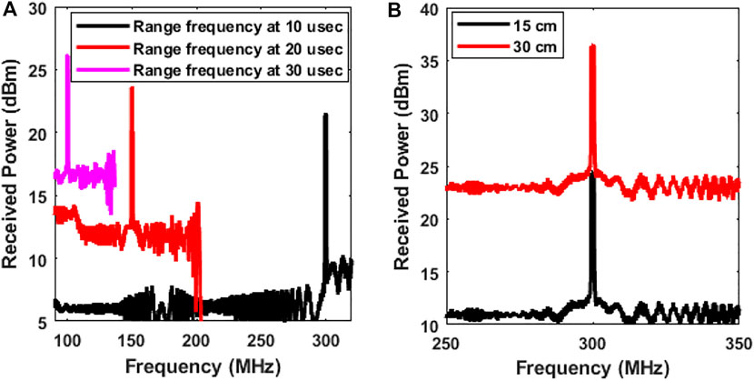
FIGURE 3. Target detection in clear weather at range 750 m. (A) Range frequency measurement at different sweep times of 30, 20, and 10 µsec; (B) target detection with different receiver aperture sizes.
Range frequency (fr) is calculated theoretically using Eq. 3 as 300 MHz at a sweep time of10 µsec. The same is shown using the simulated results in Figure 3A where the peak is observed at 300 MHz frequency at the power level of 22.5 dBm. Similarly, the theoretical values of 150 MHz range frequency at 20 µsec and 100 MHz at 30 µsec are calculated, and similar peaks can be observed in Figure 3A. Subsequently, the target range can further be measured if range frequency is known by simply reversing Eq. 1 as
The measured value of the range and range-frequency using mathematical as well as simulation methods affirms that the demonstrated photonic radar system has precisely reported detection and ranging of the stationary target. Likewise, the received power measured using an electrical analyzer as 23.10 dBm and 26.51 dBm at 10 and 30 µsec, respectively, confirms sufficient signal strength at the photodiode. Consequently, SNR is measured as 68 dB and 74 dB at 10 and 30 µsec, respectively. Likewise, range frequency can be premeditated keeping the range static and varying the time sweep and bandwidth. Figure 3B depicts the effect of increasing the aperture area of the telescopic lens. The proposed system observes an increase of 13 dBm in the signal strength of the received echoes. The signal strength of 23 dBm and 36 dBm is measured using the receiver lens with an aperture area of 15 and 30 cm, respectively. Thus, the size of the receiver can be kept as per the requirements of the received echo signal strength if the total size is not of much concern. In this work, the size of aperture lens at the transmitter is fixed as 5 cm, and at the receiver, as 15 cm.
Autonomous vehicles are reliant upon photonic radars on behalf of most of the conveniences, and hence, they should be able to deliver extended range visibility for precise recognition of the target even under severe atmospheric conditions. Usually, zero visibility in the AV segment is the visibility of fewer than 50 m under adverse atmospheric conditions such as fog, snow, or rain and may possibly lead to mishaps [35]. Therefore, the performance of the proposed photonic radar system is further studied under the effects of fog and rain. Fog is the amalgamation of several rudiments that result in dispossession of overall system performance [36, 37]. Usually, the range in foggy surroundings is in hundreds of meters (less than 1 km) but can be abridged to a few meters in the course of dense foggy conditions. For the proposed photonic radar, the system is subjected to 4 different fog conditions as per the international visibility code [38], i.e., thick fog with the visibility of 200 m and the attenuation value of 70 dB/km, heavy fog with the visibility of 350 m and the attenuation value of 50 dB/km, moderate fog with the visibility of 500 m and the attenuation value of 28.9 dB/km, and light fog with the visibility of 770 m and the attenuation value of 18.3 dB/km.
Rain is another key-degrading aspect on the effectiveness of photonic radar, particularly at the mm-wave band. Hence, the effect of heavy rain and its droplet size is obligatory to be considered on the competence of the proposed system, particularly in the AV applications. The attenuation due to rain is dependent upon the droplet size and rate of pouring, and it can be computed as [39]
where Arain is the attenuation due to rain, Ro is the rate of rainfall in mm/hr, and k and α are the power law factors of dependent variables such as droplet size, frequency, and temperature and can be computed using the Marshall–Palmer distribution [40]. At 77 GHz operating frequency, the corresponding values of k and α are computed as 1.210 and 0.772. Considering the heavy rain condition at 55 mm/h, the attenuation Arain comes out as 24 dB/km. Likewise, computed attenuation for mild rain at 25 mm/h is 14.25 dB/km, for light rain at 5 mm/h is 4 dB/km, and for drizzle at 0.25 mm/h attenuation is 0.6 dB/km.
Another important factor to be considered in photonic radar modeling is the selection of optimal operating wavelength and frequency bands as the higher frequency used in the mm-wave band tends to be affected by atmospheric fluctuations especially in the AV sector. Authors have considered designing target models such as losses viz. geometric loss, transmission loss, and pointing and scintillation loss. The system is further exposed to refractive index variation by utilizing the gamma–gamma distribution model [41].
As shown in Figures 4A and B, different fog conditions with corresponding attenuation are summed up at 10 and 30 µsec, respectively. Similarly, in Figures 5A and B, strong-to-weak rainy conditions with corresponding attenuation are summed up at 10 and 30 µsec, respectively. The improvement of ≈ 4–5 dBm received power is observed at increased sweep time, and the improvement of ≈ 3–5 dB is observed in the SNR value.
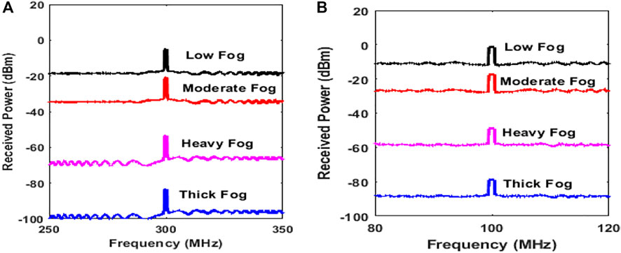
FIGURE 4. Target detection under foggy weather at range 750 m with range frequency at different attenuation levels with sweep times (A) 10 µsec and (B) 30 µsec.
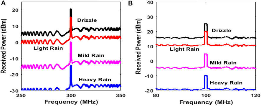
FIGURE 5. Target detection under rainy weather at range 750 m with range frequency at different attenuation levels with sweep times (A) 10 µsec and (B) 30 µsec.
The comprehensive values of the received power (dBm) and SNR (dB) observed by the electrical analyzer at different attenuation levels are specified in Table 2.
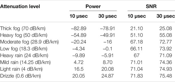
TABLE 2. Power and SNR values obtained at different attenuation levels.
Figure 6 depicts the SNR value under the influence of atmospheric fluctuations (varying attenuation levels) over a wide transmission range (up to 3000 m) detected via the photo detector at different sweep times. For successful reception of signals, the minimum acceptable SNR value is fixed at 20 dB. With a sweep time of 10 µsec under thick fog conditions (70 dB/Km), the echo is received at 905 m, while at a sweep time of 30 µsec, the echo is received at 950 m. Similarly, ≈ 40–50 m of improvement can be seen in other conditions as well. Due to the limitation of the designed system and parameter constraints, the maximum range observed was 3000 m, while mild rain to drizzle conditions were still to be verified for the maximum transmission range. Hence, it can be concluded that the proposed photonic radar can sense the maximum distance at severe atmospheric conditions, whereas the maximum transmission range can be well above 10000 m for light rain conditions (4 dB/km).
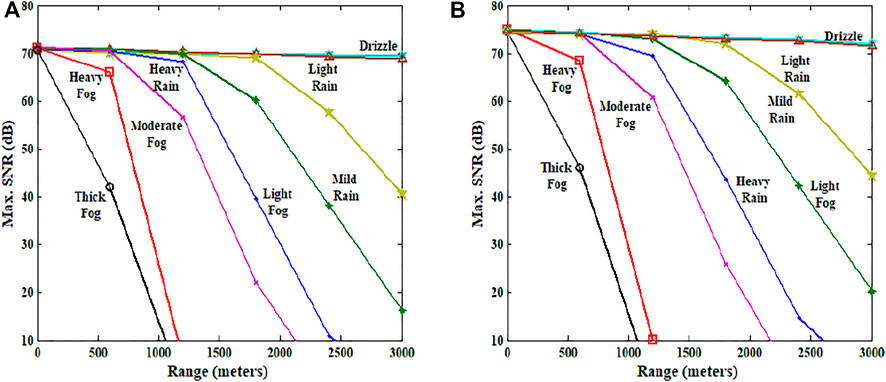
FIGURE 6. SNR (dB) vs range at different attenuation levels (atmospheric conditions) at (A) 10 µsec and at (B) 30 µsec.
Figure 7 shows the relation between SNR and attenuation at 10 and 30 µsec sweep times to understand the corresponding variations between the signal and noise with respect to the attenuation. Initially, for an attenuation level up to 30 db/km at a sweep time of 10 and 30 µsec, the SNR value holds good up to 70 dB and 74 dB, respectively, but, as the attenuation increases from 30 dB/km to 75 dB/km, the SNR linearly decreases toward zero. The graph clearly indicates that beyond 70 dB/km, the SNR falls below the 20 dB value which is minimally acceptable [42]. The graph also testifies the proposed model signal reception up to 70 db/km of attenuation conditions.
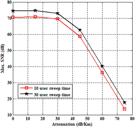
FIGURE 7. Measured SNR at 10 and 30 µsec sweep times.
Conclusion
In this article, the frequency-modulated continuous wave (FMCW)–driven photonic radar was modeled for range detection of stationary targets by sensing reflected echoes under the influence of atmospheric fluctuations in terms of attenuation using the direct detection method. Successful target detection and ranging have been reported, and furthermore, the system is verified under weak-to-strong turbulences. Outcomes of the proposed system achieve an enhanced target range of 905 m under thick fog condition, 1090 m with heavy fog, 1920 m with moderate fog, and 2280 m with heavy rain. Presented results conclude that atmospheric fluctuations (70 dB/km and above) affect the range resolution of the photonic radar. Furthermore, augmentation in the attenuation due to smog (smoke + fog) conditions of cities may affect the working of AVs which must be considered along. It can further be extended to a range and detect moving targets with multiple-object tracking.
Data Availability Statement
The raw data supporting the conclusions of this article will be made available by the authors, without undue reservation.
Author Contributions
AS: writing original draft, methodology, and simulations; SC: writing review and editing, software; JM: writing review and editing, supervision; MS: visualization; SA: resources; JN: formal analysis; LW: data curation.
Funding
This research work is funded by TSRI Fund (CU_FRB640001_01_21_8).
Conflict of Interest
The authors declare that the research was conducted in the absence of any commercial or financial relationships that could be construed as a potential conflict of interest.
Publisher’s Note
All claims expressed in this article are solely those of the authors and do not necessarily represent those of their affiliated organizations, or those of the publisher, the editors, and the reviewers. Any product that may be evaluated in this article, or claim that may be made by its manufacturer, is not guaranteed or endorsed by the publisher.
Acknowledgments
The authors would like to thank Guru Nanak Dev University, Amritsar for supporting the research work. The authors would also like to thank Optiwave corporation, Canada specially Dr. Ahmad Atieh for providing the technical support as well as valuable software OptiSystemTM to carry this research work. The authors also would like to thank Taif University Researchers supporting project number (TURSP-2020/228), Taif University, Taif, Saudi Arabia.
References
1. Zhang H, Li J, Wang T, Lin H, Zheng Z, Li Y, et al. A Manifold Learning Approach to Urban Land Cover Classification with Optical and Radar Data. Landscape Urban Plann (2018) 172:11–24. doi:10.1016/j.landurbplan.2017.12.009
2. Tong X, Luo X, Liu S, Xie H, Chao W, Liu S, et al. An Approach for Flood Monitoring by the Combined Use of Landsat 8 Optical Imagery and COSMO-SkyMed Radar Imagery. ISPRS J Photogrammetry Remote Sensing (2018) 136:144–53. doi:10.1016/j.isprsjprs.2017.11.006
3. Shen W, Li M, Huang C, Tao X, Wei A. Annual forest Aboveground Biomass Changes Mapped Using ICESat/GLAS Measurements, Historical Inventory Data, and Time-Series Optical and Radar Imagery for Guangdong Province, China. Agric For Meteorology (2018) 259:23–38. doi:10.1016/j.agrformet.2018.04.005
4. Poggio L, Gimona A. Assimilation of Optical and Radar Remote Sensing Data in 3D Mapping of Soil Properties over Large Areas. Sci Total Environ (2017) 579:1094–110. doi:10.1016/j.scitotenv.2016.11.078
5. Skog I, Handel P. In-Car Positioning and Navigation Technologies-A Survey. IEEE Trans Intell Transport Syst (2009) 10:4–21. doi:10.1109/tits.2008.2011712
6. Mautz R. Combination of Indoor and Outdoor Positioning. In: 1st International Conference on Machine Control & Guidance (2008). p. 1–9.
7. Kutila M, Pyykönen P, Ritter W, Sawade O, Schäufele B. Automotive LIDAR Sensor Development Scenarios for Harsh Weather Conditions. In: 2016 IEEE 19th International Conference on Intelligent Transportation Systems (ITSC). IEEE (2016). p. 265–70. doi:10.1109/itsc.2016.7795565
8. Haykin S. Cognitive Radar: a Way of the Future. IEEE Signal Process Mag (2006) 23:30–40. doi:10.1109/msp.2006.1593335
10. Scheer JA. Coherent Radar System Performance Estimation. In: IEEE International Conference on Radar. IEEE (1990). p. 125–8.
11. Allen CT, Chong SK, Cobanoglu Y, Gogineni S. Development of a 1319-nm Laser Radar Using Fiber Optics and RF Pulse Compression. Kansas: University of Kansas Technical Report ITTC-RSL-FY2002-TR-18680-01 (2002).
12. Yang W-j., Zhao J-g., Du X-p., Zeng Z-y., Wang Q. Laser Diode Transmitter for Laser Radar Based on FM Ranging Principles. In: International Symposium on Photoelectronic Detection and Imaging 2007: Optoelectronic System Design, Manufacturing, and Testing. IEEE (2008). p. 662408.
13. Karlsson CJ, Olsson FÅA. Linearization of the Frequency Sweep of a Frequency-Modulated Continuous-Wave Semiconductor Laser Radar and the Resulting Ranging Performance. Appl Opt (1999) 38:3376–86. doi:10.1364/ao.38.003376
14. Ghassemlooy Z, Popoola W, Rajbhandari S. Optical Wireless Communications: System and Channel Modelling with Matlab®. London: CRC Press (2019).
15. Harris M, Young RI, Köpp F, Dolfi A, Cariou J-P. Wake Vortex Detection and Monitoring. Aerospace Sci Tech (2002) 6:325–31. doi:10.1016/s1270-9638(02)01171-9
16. Dolfi-Bouteyre A, Canat G, Valla M, Augere B, Besson C, Goular D, et al. Pulsed 1.5-$\mu$m LIDAR for Axial Aircraft Wake Vortex Detection Based on High-Brightness Large-Core Fiber Amplifier. IEEE J Select Top Quan Electron. (2009) 15:441–50. doi:10.1109/jstqe.2008.2010463
17. Itu‐R P. Specific Attenuation Model for Rain for Use in Prediction Methods. Switzerland: Recommendation P. 838-3, ITU‐R Recommendations, P Series (2005).
19. Peynot T, Underwood J, Scheding S. Towards Reliable Perception for Unmanned Ground Vehicles in Challenging Conditions. In: 2009 IEEE/RSJ International Conference on Intelligent Robots and Systems. IEEE (2009). p. 1170–6. doi:10.1109/iros.2009.5354484
20. Rasshofer RH, Spies M, Spies H. Influences of Weather Phenomena on Automotive Laser Radar Systems. Adv Radio Sci (2011) 9:49–60. doi:10.5194/ars-9-49-2011
21. Wojtanowski J, Zygmunt M, Kaszczuk M, Mierczyk Z, Muzal M. Comparison of 905 Nm and 1550 Nm Semiconductor Laser Rangefinders’ Performance Deterioration Due to Adverse Environmental Conditions. Opto-Electronics Rev (2014) 22:183–90. doi:10.2478/s11772-014-0190-2
22. Hasirlioglu S, Riener A, Huber W, Wintersberger P. Effects of Exhaust Gases on Laser Scanner Data Quality at Low Ambient Temperatures. In: 2017 IEEE Intelligent Vehicles Symposium (IV). IEEE (2017). p. 1708–13. doi:10.1109/ivs.2017.7995954
23. Bijelic M, Gruber T, Ritter W. A Benchmark for Lidar Sensors in Fog: Is Detection Breaking Down? In: 2018 IEEE Intelligent Vehicles Symposium (IV). IEEE (2018). p. 760–7.
24. Ramasubramanian K, Ramaiah K. Moving from Legacy 24 GHz to State-Of-The-Art 77-GHz Radar. ATZ Elektron Worldw (2018) 13:46–9. doi:10.1007/s38314-018-0029-6
25. Adany P, Allen C, Rongqing Hui R. Chirped Lidar Using Simplified Homodyne Detection. J Lightwave Technol (2009) 27:3351–7. doi:10.1109/jlt.2009.2016220
26. Pierrottet D, Amzajerdian F, Petway L, Barnes B, Lockard G, Rubio M. Linear FMCW Laser Radar for Precision Range and Vector Velocity Measurements. MRS Online Proc Libr (Opl) (2008) 1076. 1. doi:10.1557/proc-1076-k04-06
27. Elghandour A, Dianren C. Study on Detection Techniques of Distance and Velocity by Chirped LIDAR. In: 2012 International Conference on Optoelectronics and Microelectronics. IEEE (2012). p. 354–8. doi:10.1109/icoom.2012.6316290
28. Nguyen D-N, Bohata J, Komanec M, Zvanovec S, Ortega B, Ghassemlooy Z. Seamless 25 GHz Transmission of LTE 4/16/64-QAM Signals over Hybrid SMF/FSO and Wireless Link. J Lightwave Technol (2019) 37:6040–7. doi:10.1109/jlt.2019.2945588
29. Elghandour AH, Ren CD. Modeling and Comparative Study of Various Detection Techniques for FMCW LIDAR Using Optisystem. In: International Symposium on Photoelectronic Detection and Imaging 2013: Laser Sensing and Imaging and Applications. IEEE (2013). p. 890529. doi:10.1117/12.2034878
30. Zhou P, Zhang F, Pan S. Generation of Linear Frequency-Modulated Waveforms by a Frequency-Sweeping Optoelectronic Oscillator. J Lightwave Technol (2018) 36:3927–34. doi:10.1109/jlt.2018.2854713
31. Coutinho OL, Almeida VR, Oliveira JEB. Analysis of Analog Fiber Optical Links Based on DSB+ C and SSB+ C Modulation Techniques. In: SBMO/IEEE MTT-S International Conference on Microwave and Optoelectronics. IEEE (2005). p. 439–43.
35. Miclea R-C, Dughir C, Alexa F, Sandru F, Silea I. Laser and LIDAR in A System for Visibility Distance Estimation in Fog Conditions. Sensors (2020) 20:6322. doi:10.3390/s20216322
36. Anbarasi K, Hemanth C, Sangeetha RG. A Review on Channel Models in Free Space Optical Communication Systems. Opt Laser Tech (2017) 97:161–71. doi:10.1016/j.optlastec.2017.06.018
37. Al Naboulsi M, Sizun H, de Fornel F. Fog Attenuation Prediction for Optical and Infrared Waves. Opt Eng (2004) 43:319–29. doi:10.1117/1.1637611
38. Awan MS, Marzuki EL, Hillbrand B, Nadeem F, Khan MS. Cloud Attenuations for Free-Space Optical Links. In: 2009 International Workshop on Satellite and Space Communications. IEEE (2009). p. 274–8. doi:10.1109/iwssc.2009.5286364
39. Rashidi F, He J, Chen L. Spectrum Slicing WDM for FSO Communication Systems under the Heavy Rain Weather. Opt Commun (2017) 387:296–302. doi:10.1016/j.optcom.2016.11.070
40. Olsen R, Rogers D, Hodge D. The aRbrelation in the Calculation of Rain Attenuation. IEEE Trans Antennas Propagat (1978) 26:318–29. doi:10.1109/tap.1978.1141845
Keywords: photonic radar, frequency-modulated direct detection, signal-to-noise ratio, adverse weather conditions, autonomous vehicle
Citation: Sharma A, Chaudhary S, Malhotra J, Saadi M, Al Otaibi S, Nebhen J and Wuttisittikulkij L (2021) A Cost-Effective Photonic Radar Under Adverse Weather Conditions for Autonomous Vehicles by Incorporating a Frequency-Modulated Direct Detection Scheme. Front. Phys. 9:747598. doi: 10.3389/fphy.2021.747598
Received: 26 July 2021; Accepted: 03 August 2021;
Published: 16 September 2021.
Edited by:
Santosh Kumar, Liaocheng University, ChinaReviewed by:
Sneha Kumari, Indian Institute of Technology Patna, IndiaRahul Kumar Gangwar, Peking University, China
Copyright © 2021 Sharma, Chaudhary, Malhotra, Saadi, Al Otaibi, Nebhen and Wuttisittikulkij. This is an open-access article distributed under the terms of the Creative Commons Attribution License (CC BY). The use, distribution or reproduction in other forums is permitted, provided the original author(s) and the copyright owner(s) are credited and that the original publication in this journal is cited, in accordance with accepted academic practice. No use, distribution or reproduction is permitted which does not comply with these terms.
*Correspondence: Abhishek Sharma, er.abhisheksharma07@gmail.com; Sushank Chaudhary, sushankchaudhary@gmail.com; Lunchakorn Wuttisittikulkij, lunchakorn.w@chula.ac.th