Non-Diffracting Light Wave: Fundamentals and Biomedical Applications
 Yu-Xuan Ren
 Hongsen He
 Huajun Tang
 Kenneth K. Y. Wong2,3*
- 1Institute for Translational Brain Research, Shanghai Medical School, Fudan University, Shanghai, China
- 2Department of Electrical and Electronic Engineering, University of Hong Kong, Pokfulam, Hong Kong, SAR China
- 3Advanced Biomedical Instrumentation Centre, Hong Kong Science Park, Shatin, Hong Kong, SAR China
The light propagation in the medium normally experiences diffraction, dispersion, and scattering. Studying the light propagation is a century-old problem as the photons may attenuate and wander. We start from the fundamental concepts of the non-diffracting beams, and examples of the non-diffracting beams include but are not limited to the Bessel beam, Airy beam, and Mathieu beam. Then, we discuss the biomedical applications of the non-diffracting beams, focusing on linear and nonlinear imaging, e.g., light-sheet fluorescence microscopy and two-photon fluorescence microscopy. The non-diffracting photons may provide scattering resilient imaging and fast speed in the volumetric two-photon fluorescence microscopy. The non-diffracting Bessel beam and the Airy beam have been successfully used in volumetric imaging applications with faster speed since a single 2D scan provides information in the whole volume that adopted 3D scan in traditional scanning microscopy. This is a significant advancement in imaging applications with sparse sample structures, especially in neuron imaging. Moreover, the fine axial resolution is enabled by the self-accelerating Airy beams combined with deep learning algorithms. These additional features to the existing microscopy directly realize a great advantage over the field, especially for recording the ultrafast neuronal activities, including the calcium voltage signal recording. Nonetheless, with the illumination of dual Bessel beams at non-identical orders, the transverse resolution can also be improved by the concept of image subtraction, which would provide clearer images in neuronal imaging.
Introduction
Light propagates rectilinearly and experiences diffraction in daily life [1]. The light diffraction is the consequence of the violation of the rectilinear propagation. The diffraction is defined as any deviation from rectilinear propagation [1]. Strong diffraction appears when the transverse dimensions are comparable with the wavelength. Strong diffraction is more pronounced for long waves such as water or sound waves, while being less appreciable in optics. The diffraction is in charge of the beam divergence in the free-space propagation and propagation into the shadow region [1]. Diffraction, as a natural wave property, features the nonhomogeneous distribution in transverse intensity. Durnin has introduced the controversial term “non-diffracting beam” into optics in 1987 [2, 3]. Since then, the non-diffracting beams have been intensively investigated in both theory and experiment. The “non-diffracting” beams do not spread upon propagation [4]. Discussions related to the “non-diffracting” term revived interest in light diffraction and resulted in a new research direction of the localized transfer of electromagnetic energy in classical optics [1]. Diffraction usually appears in transversally unbounded beams, e.g., the Gaussian beam. In a vacuum, the size of the normal Gaussian beam would increase within the Rayleigh range owing to diffraction. However, the non-diffracting beam would preserve the size and shape during propagation for a longer distance than the Rayleigh range. In optics, non-diffracting propagation can be produced in media such as a waveguide or nonlinear material. The beams then propagate as guided modes or spatial optical solitons, respectively.
Since the prediction, the non-diffracting beam includes a family of beams that preserve the shape during propagation and penetrate deeper tissue without degrading the shape owing to self-recovery [3]. The most commonly used and successful “non-diffracting” beams are the Bessel beam and Airy beam. In 1979, Berry and Balazs [5] revealed that the solution to the free-particle nonlinear Schrödinger equation is the quantum-mechanical counterpart of the paraxial diffraction equation, i.e., the Airy wave packets. The ideal Airy beam has infinite energy and it is impractical to generate the Airy beam experimentally. In 2007, Siviloglou and Christodoulides adopted an apodization aperture function
Biomedical applications require remote sensing, probing, and stimulation of biological matter, e.g., cells and tissue. Optical means have been non-invasive, non-contact for optogenetics, optical tweezers, for instance, the optical manipulation and sensing of cell motion in vivo. However, the light in biological matter often experiences strong scattering and attenuation upon propagation, smearing the signal in those applications. In particular, the green light results in a larger scattering coefficient. A longer wavelength was introduced to increase the penetration depth but requires NIR fluorophore. One possible means to overcome scattering is using the non-diffracting beam, which preserves the shape over a distance longer than the Gaussian Rayleigh range. Here, the theory, generation, and significant features of many “non-diffracting” beams are reviewed, with an emphasis on the biomedical applications of those fascinating beams, including the multimodal biomedical imaging [11, 23–26], optical micromanipulation [10, 27, 28], and optical transfection [29–31]. Specifically, we introduce the use of non-diffracting beams to overcome the challenges arising from various applications, including two-photon microscopy, Raman spectroscopy, and optical manipulation. This feature is unique and important for many biomedical applications, e.g., fluorescence microscopy and optical manipulation. The two-dimensional (2D) optical Airy wave packet can transport microparticles along curved paths. Particles follow the parabolic trajectories along the transverse acceleration in the light field. The non-diffracting and self-healing [32] nature of Airy beam has extended the field of view (FOV) in light-sheet microscopy [33] or was imaged through scattering and highly turbulent medium [34, 35], while the bent fluorescence trajectory commensurate with self-acceleration has been adopted to localize the molecule in 3D super-resolution microscopy along the axial direction [36]. In addition, the pulse laser would broaden its spectrum in the dispersive medium, resulting in the broadened temporal width of the pulse. Temporally non-diffracting wave preserves the temporal width thanks to nonlinearity.
This review article discusses the fundamental concept of non-diffracting beams, experimental techniques to create those beams, the major features of the non-diffracting beams, and the biomedical applications. In Fundamental Concepts of Non-Diffracting Wave, we review various types of non-diffracting beams, including Bessel, Airy, vortex, Mathieu, lattice, and pulsed beams. In Generation of Non-Diffracting Optical Beams, various techniques to create the non-diffracting beams are introduced, for example, axicon, metasurface, tailored fiber, spatial light modulator (SLM), and nonlinear crystal. In Features of Non-Diffracting Optical Beams, we introduce the major features of the non-diffracting beams. In Biomedical Application With Non-Diffracting Waves, we introduce some typical biomedical applications using non-diffracting beams. In the last section, we predict that the non-diffracting beam would continue to improve the biomedical tools, including biomedical imaging and optical manipulation.
Fundamental Concepts of Non-Diffracting Wave
The non-diffracting coherent field comprehends as the interference of plane waves with conical vectors. The angular spectrum suggests sufficient conditions for the non-diffracting propagation. The intensity profiles of non-diffracting beams can be produced by manipulating the amplitudes and phases of the plane wave components in the angular spectrum. Specifically, the integral form of the non-diffracting beam in circular cylindrical coordinates
where
and
where
The description of Eq. 3 includes families of fundamental non-diffracting beams, which are solutions of the Helmholtz equation, e.g., Mathieu beam with elliptic and hyperbolic transverse profiles, transverse parabolic beams, and the profile produced by the interference of a finite number of tilted plane waves [37]. The spectrum of the fundamental family of non-diffracting wave fields has a respective function, which is defined on a ring-shaped region in frequency space [37]. Figure 1 shows the spatial spectrum, amplitude, and phase of the periodic hexagonal, quasiperiodic fivefold tilings, Bessel beam, even Mathieu beam, and even Webber beam [39]. The Bessel beam has a circular spectrum (Figure 1C), while the triangular lattice has a spectrum of three spots (Figure 1A). The wave vectors for the non-diffracting beams lie on a cone, and those beams are the superposition of conical waves with modulated amplitude.
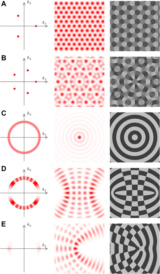
FIGURE 1. Non-diffracting beams. (Left) Spatial spectrum, (middle) intensity, and (right) phase profiles for (A) periodic hexagonal, (B) quasiperiodic fivefold tilings, (C) Bessel beam, (D) even Mathieu beam, (E) even Webber beam. Reproduced with permission from the original author [38].
It is noteworthy to mention that the conical superpositions are only families of the non-diffracting beam. The non-diffracting beam actually covers a broad area of optical physics as the solution to the Maxwell equation or nonlinear Schrödinger equation [5, 17]. One example is the non-diffracting Airy beam, which was predicted in 1979 [5] but was experimentally observed nearly 30 years later in 2007 [6, 7]. Those kinds of non-diffracting waves can be in the form of not only optics but also, in general, any physical waves in nature, e.g., electrons [40]. In this section, we review the most common non-diffracting shape-preserving beams, including the Airy beam, Bessel beam, vortex beam, Mathieu beam, lattice and Kaleidolscopic beam, and the pulsed non-diffracting beam.
Bessel and Airy Beams
The free-space Helmholtz equation is as follows [2]:
In source-free region, i.e., z ≥ 0, an exact scalar solution to Eq. 4 is as follows:
where
which exactly reproduces for all z > 0 in the transverse plane normal to the propagation axis.
When
Here,
The spatial spectrum of a Bessel beam resembles an annular ring, e.g., a perfect vortex, while some types of the lattice beam can be produced by a multiple-beam interference. To mention that the Bessel beam propagates in a straight line and preserves the shape. There is a connection between the lattice and the Bessel beam. Figures 2A–F show the transverse profiles and propagation of the higher-order Bessel-Gaussian beams (A) at the focus (z = 0), (B) in the far-field (z = 10 mm), and side-view profile near the focus [41]. In contrast, the 0th-order Bessel-Gaussian beam shows a needle-like structure near the focus (Figure 2F). Such needle-like focus structure could also be created by other types of non-diffracting beams like the symmetric Airy beam (SAB) [42].
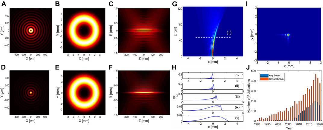
FIGURE 2. Non-diffracting Bessel and Airy beams. Square modulus of the Bessel–Gauss amplitude with azimuthal or radial vector potential (A) at the focus (z = 0), (B) in the far-field (z = 10 mm) and (C) near the focus; (D–F) similar to (A–C) but for vector potential amplitude along a Cartesian unit vector. (G) Dynamics of free-space propagation of an Airy beam with finite energy. (H) The normalized linear intensity profiles at 1) z = 0 cm, 2) 31.4 cm, 3) 62.8 cm, 4) 94.3 cm, and 5) 125.7 cm, respectively. (I) 2D Airy beam with finite energy at a distant plane (z = 50 cm). (J) The number of publications for Bessel and Airy beams increases with the year. Reprinted with permission from OSA [7, 41].
Although most of the non-diffracting beams could be understood with the conical superposition, the 1D localized propagation-invariant beam cannot be synthesized using conical superposition [6]. The nonlinear Schrödinger equation for a free particle suggests a non-spreading Airy-like wave packet. The intriguing Airy wave packets, predicted by Berry and Balazs in 1979, break the cylindrical symmetry [5]. Until 2007, the optical Airy beam has been generated in both one- and two-dimensional configurations with the spectral shaping of the light wavefront using a reconfigurable spatial light modulator (SLM) [6].
The Airy beam carries infinite energy. Practically, the finite energy Airy beam
Although the finite energy Airy beam was first produced in optics [7], the Airy wave itself could be in various forms, including the curved plasmon [12], electron [40], and plasmonics [15, 16, 43]. The application of the Airy beam has also been extended from optical manipulation [10] and biomedical imaging [11]. Figure 2J illustrates the number of publications in the Web of Science database with keywords “Airy beam” and “Bessel beam.” The number of publications on “Airy beam” grows linearly since the first demonstration of the optical Airy beam in 2007. In contrast, the number of publications with “Bessel beam” has also grown vastly with respect to the year since 1990. Those are just two representative examples of the non-diffracting beams related applications. The trend suggests that the non-diffracting beams have been very useful in interdisciplinary applications, apart from the fundamental physics itself. In addition, the beams with Airy-Bessel tempo-spatial profiles are also interesting as they combine both the spatial profile and the temporal wavepackets [44].
Non-Diffracting Vortex
Young’s double-slit experiment suggests the interference pattern of the two sub-sources. More generally, the triple slit may result in more complicated patterns with phase dislocations. Phase dislocation is a structure in the laser speckle patterns. The light wavefront may also possess line, spiral or combined wavefront dislocations. The wavefront with spiral phase is well known as the optical vortex with singularities. Assume that the slowly varying complex amplitude
Some types of non-diffracting beams belong to the class of fields with the spiral wavefront dislocations. Vortices widely exist in numerous natural phenomena, from ocean fluids to typhoons and galaxies [45]. The optical vortex is associated with the phase singularity in the field. Phase singularity is characterized by an isolated dark spot, where the amplitudes are zero and the phases are undefined. When Young’s double-slit experiment extends to 2triple-slit, we will see the phase singularity. The phase dislocation appears at the location with the nonzero value of the integral:
Here, the integration is evaluated along a closed line surrounding the singularity. The integral (9) results in the values
Figure 3 shows the spatial profile, phase, and wavefront of a plane wave and optical vortices with topological charges
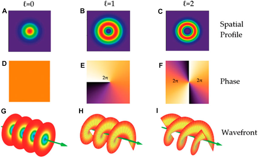
FIGURE 3. The spatial phase structure of plane waves and vortices with different topological charges. The differences between the Gaussian beam and vortex beam are shown in spatial profile (A–C), phase (D–F), and wavefront (G–I). Reproduced from Intech [46].
The vortex beam is not a fundamental feature for the non-diffracting beam. However, beams with non-diffracting amplitude and vortex phase, e.g., higher-order Bessel beams, are non-diffracting. When the amplitudes of the components of the plane wave in the angular spectrum are constant and their phases are azimuthally modulated by
where
The radius for the central intensity spot
Mathieu Beams
The Bessel beams are obtained with the angular spectrum (Eq. 3) expressed by the plane waves whose phases are conveniently modulated and the real amplitudes remain unmodulated. In contrast, a good approximation to the 0th-order Mathieu beams can be approximated if the relative phases among the components of the plane waves are constant and their real amplitudes are modified by the following [48]:
where
In 2000, Gutiérrez-Vega et al. demonstrated the Mathieu beam as a new member of the non-diffracting beam family both theoretically and experimentally. Specifically, Mathieu beams are the solutions of the Helmholtz equation under elliptical cylindrical coordinates
For a Mathieu beam with order m, the complex field is as follows:
Here,
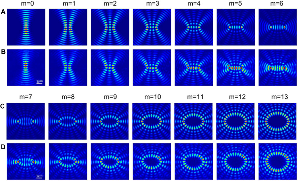
FIGURE 4. Cross-sections of Mathieu beams. (A,C) Theoretical and (B,D) experimental profiles of the Mathieu beams with different order m. Reproduced from OSA [49].
As Mathieu beams are the solutions to the Helmholtz equation in elliptical coordinates, the beam’s spatial distribution is determined by the ellipticity parameter q. For small q, the OAM per photon for a helical Mathieum beam of order m ≥ 1 originates from its m interfocal vortices. The transverse location of the vortices remains invariant during beam propagation. Interestingly, as q decreases, the foci approach the coordinate origin and all the vortices merge into a single vortex with topological charge m, i.e., the Bessel beams for q = 0. Clearly, the symmetry of the elliptical cylindrical coordinate collapses to circular cylindrical coordinates in the absence of the interfocal distance. In contradistinction to Bessel beams, however, the OAM density of HM beams depends on the azimuthal coordinate but varies as a function of the elliptic angular coordinate η. For HM beams with the same order, an increase in the ellipticity results in a horizontal stretch of the ring-like profile, deviating gradually from circular symmetry. After a critical value
Lattice and Kaleidolscopic Beams
The non-diffracting coherent field can be defined as the interference created by the plane waves with conical propagation vectors. Due to the interference, the total field can possess an appreciable beam-like intensity peak to form the non-diffracting beam. The non-diffracting beams can be generated by superposing plane waves. Two-dimensional (2D) optical patterns can be generated by interfering with multi-beams [51–54]. Normally, the amplitude mask, based on the Fourier transform, could easily convert the lattice and kaleidoscopic beams with high stability. Specifically, the non-diffracting beam is formed by multi-Gaussian beams evenly distributed on the circumference with the radius
where N represents the number of the Gaussian beams, and the output wave function near the focal region can be described as follows:
Here,
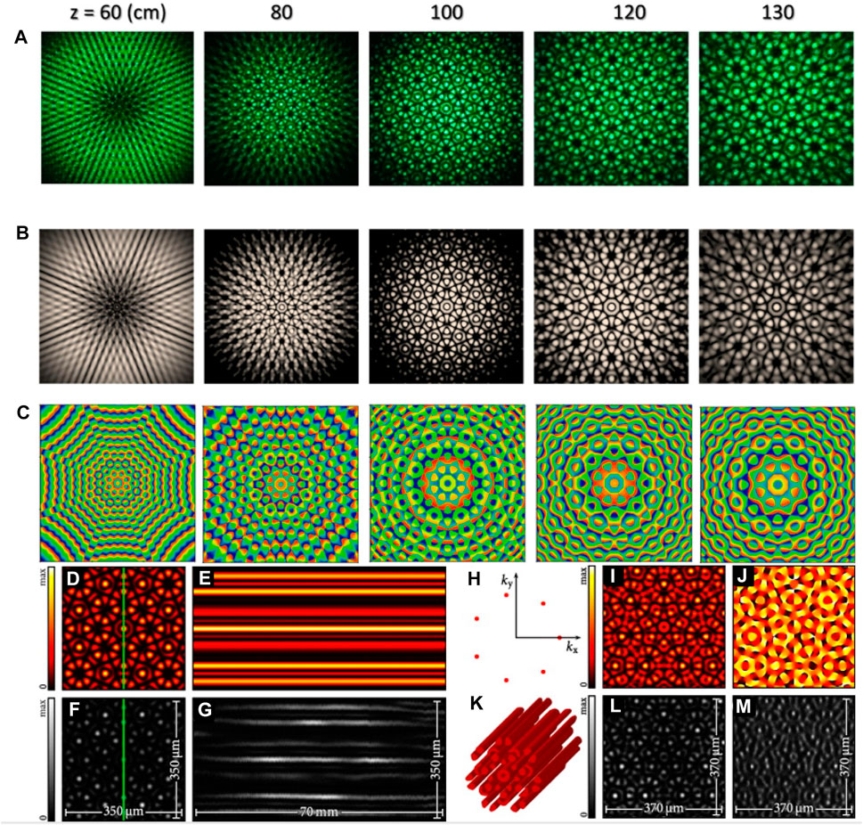
FIGURE 5. (A) Experimental and (B) numerical profiles of the high-resolution kaleidoscopic lattices in the effective non-diffracting region when N = 8. (C) Contour plots for the phase fields in (B). Simulated (D) transverse spatial pattern and (E) longitudinal non-diffracting profile of a prototypical discrete non-diffracting lattice beam. (F,G) The experiment corresponding to (D,E). Transverse intensity profile in (H) Fourier space and (I) real space, with (J) the corresponding phase in real space. (K) Iso-surface of the intensity for the non-diffracting light field, (L) observed transverse beam profile, and (M) guided beam in the discrete photonic lattice. Reproduced with permission from OSA [51]. Reproduced by permission of [55], @ IOP Publishing and Deutsche Physikalische Gesellschaft.
Recall that function A in Eq. 3 describes the amplitude and phase modulation of the angular spectrum of the non-diffracting beam. Usually, a continuous function of the azimuthal angle
where
The azimuthal angles
For the lattice beams, i.e., the Fourier transform of N plane waves, the function can be described as follows.
where
Pulsed Non-Diffracting Beams
The non-diffracting beam is a class of exact solutions to the source-free homogeneous Helmholtz equation. The non-diffracting beams do not change the transverse intensity under free propagation. In a real application, the diffraction is barely overcome and approximations to the non-diffracting beams could be synthesized. Such beam is termed a pseudo-non-diffracting beam. The propagation of the ideal non-diffracting beam appears as a consequence of the superposition of the angular spectrum. The angular spectrum is mathematically expressed using the Dirac delta function. The counterpart of the spatial non-diffracting beam is the pulsed non-diffracting beam. The ultrashort-pulsed laser could be achieved in the fiber laser using the mode-locking achieved by a saturable absorber or nonlinear polarization rotation [56–58]. The pulsed non-diffracting beam includes the pulsed laser beam with the spatially non-diffracting feature or the temporally non-dispersive beam. The temporally non-dispersive beam is very interesting in laser dynamics, including the temporal soliton in a fiber laser [57, 58]. In real biomedical imaging applications, the spatially non-diffracting and pulsed laser beam is very useful in multiphoton microscopy to extend the focal depth and the focal volume. This type of pulsed non-diffracting beam could be produced by passing the pulsed laser through a standard SLM to shape the transverse pattern. Combined with spatial modulation, it is possible to generate highly nonparaxial accelerating beams with an ultrashort temporal profile [59]. Additionally, the pulsed laser beam would improve the signal-noise-ratio (SNR) of multiphoton microscopy using a mechanism of temporal focusing.
Generation of Non-Diffracting Optical Beams
Most laser resonators produce a beam with a Gaussian profile, which could be confined to a small spot. The beam size is affected by diffraction as the beam propagates [60]. The more tightly a beam is focused, the faster it will diverge [60]. When a Gaussian beam irradiates on a spatially designed hologram, the beam profile changes depending on the information encoded in the hologram. This would be used to generate beams with almost any profile.
Standard Optical Components
The light field was shaped using the computer-generated hologram, and the earlier version of the hologram was printed onto a transparency film [60–63]. Nowadays, with advanced manufacturing technology, computer-generated holography can also be loaded onto the twisted nematic liquid crystal or etched into the silica substrate [64, 65]. However, due to the limit in wavelength like the terahertz wave or microwave, and the specific application, e.g., the fiber based optical communication, there are still standard optical components that cannot be replaced with the SLM. In this section, we briefly overview the most commonly used optical components to shape the electromagnetic field.
The vortex beam is generated by illuminating the Gaussian beam onto a spiral phase plate (SPP) (Figures 6A,B). Typically a 0th-order Bessel beam would be produced by illuminating the Gaussian beam onto an axicon, which is a conical-shaped lens (Figure 6C) [66]. The axial length of the 0th-order Bessel beam can be controlled through the apex angle for the axicon and the lateral size of the main lobe for the Bessel beam could be controlled by the diameter of the incident Gaussian beam. High-order Bessel beam can be produced by illuminating a vortex beam through the axicon [66]. The order of the Bessel beam is also associated with the TCs of the vortex. Combining the axicon and the SPP together, the high-order Bessel beam could be created by a single optical element. Figure 6D shows the structure of the helical axicon for generating the 6th-order Bessel beam. The high-order Bessel beam maintains a doughnut intensity distribution along the axial direction, and the size of the dark area increases with the beam order (Figure 6E).
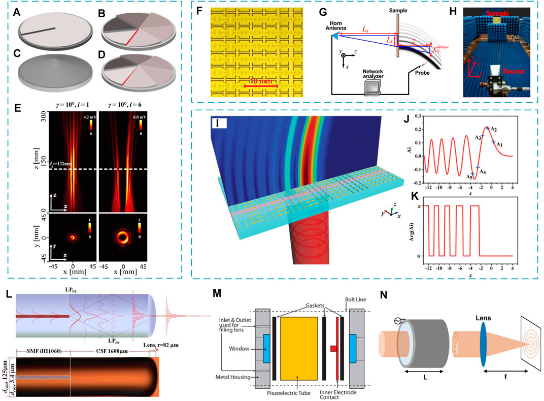
FIGURE 6. Schematics of the SPP with the TCs of (A) 1 and (B) 6, (C) the axicon, and (D) the helical axicon with the topological charge of 6. (E) Experimental beam profiles of the high-order Bessel beams created by the helical axicons. The first (second) row shows the longitudinal (transverse) profiles [66]. (F) A part of the fabricated metasurface to convert the nondiffracting Airy beam in the microwave regime. Near-field scanning (G) layout and (H) experimental setup for the Airy beam generation in the microwave regime [67]. (I) Schematics of a plasmonic metasurface capable of producing the Airy beam using the gold nanorod. (J) Linear profile of Airy function. Blue labels mark the amplitude values used for amplitude modulation. (K) Binary phase pattern of the Airy beam [68]. (L) (Top) Schematic of Bessel-like beam generation (BBG) in the all-fiber device through multi-beam interference. (Bottom) Photographic image of the manufactured all-fiber BBG device and the corresponding geometrical scales [69]. (M) Components of the TAG lens [70, 71]. (N) Geometry of the cylindrical acousto-optic modulator for generating the ultra-high speed dynamic Bessel beams [72]. Reproduced with permission from OSA [66, 71]; APS [67], and Wiley [73]. Reproduced from OSA [69, 72].
Benefited from the flexibility of tailoring the amplitude and phase of electromagnetic waves, metasurfaces have extensively generated various complex field profiles, such as Airy beams [67, 68, 74, 75]. Figure 6F shows a Huygens’ metasurface design of a metal capacitor sandwiched between dual-pair U-shaped resonators [67]. Such a metasurface can convert the microwave into an Airy beam using the layout (Figure 6G) and the experimental setup (Figure 6H). Figure 6I shows the nanorod-based configuration of a metasurface for generating plasmonic Airy beams [68]. By changing the nanorod configuration, the phase and amplitude will be simultaneously engineered.
A tunable non-diffracting Bessel beam can be produced in multimode optical fiber [76]. A concentric ring pattern was created by the multimode interference along the silica fiber, which was then concentrated by the integrated micro-lens to create a Bessel-like beam [69]. A representative all-fiber integrated structure for creating the Bessel-like beam is demonstrated in Figure 6L [69]. In addition, multiscale Bessel beams can be created through a tunable acoustic gradient index (TAG) lens (Figure 6M). By applying variable electrical driving signals, the ring spacings, the central spot size, and the lens working distance can be reconfigured [70, 71]. The TAG lens elongates the axial range of imaging, i.e., the depth of view, and consequently provides fast volumetric speed [77]. The axisymmetric acousto-optic device combined with spatial filtering makes it possible to generate the dynamic Bessel beams at ultrahigh speed (Figure 6N) [72]. The mode-locked fiber laser can also be converted to a non-diffracting beam, e.g., an Airy beam through an external cubic phase plate [78], and has been demonstrated at the output wavelength of 1.0 μm.
Spatial Light Modulator
The liquid crystal molecule presents an anisotropic optical refractive index. The orientation of the liquid crystal molecule will change under an external electric field. The global orientation of the molecules inside a liquid crystal cell would display anisotropic optical transmission. This property has been applied to make liquid crystal modulators. SLM adopts millions of liquid crystal cell units to change the phase of a light wavefront locally, allowing control over the amplitude, phase, and thus polarization state of the beam in space and time. SLM is a general term that includes liquid crystal microdisplays and digital micromirror devices (DMD). The liquid crystal SLM provides high spatial resolution due to the advancement in semiconductor technology and the temporal resolution (refresh rate) of the SLM on the order of hundreds of frames per second. However, the DMD provides orders of magnitude faster (tens of thousands of frames per second) compared to the liquid crystal SLM but suffers from low diffraction efficiency [79]. These two devices are complementary and, in those applications, require high speed. The DMD is the best choice, while SLM performs better in diffraction efficiency.
An SLM is commonly used for the generation of non-diffracting optical beams due to its programmable property. Figures 7A–C show the phase modulation for generating an apertured Gaussian, a Bessel, and an Airy profile, which can all be realized by a single SLM [43, 80]. The intensity distribution of a Bessel beam along the axial direction can be modulated by adjusting the concentric ring patterns on the SLM [84]. For instance, a binary concentric ring pattern overlaid on a quadratic phase pattern allows the tailoring of the axial intensity of the Bessel focus [84]. For high-order Bessel beams, a spiral phase mask is superimposed with the concentric phase mask (Figure 7D) [81, 85]. The lateral shape of the high-order Bessel beam is controlled by order of the spiral phase mask (Figure 7E) [82]. Adjustable Airy trajectories in the 3D space are achieved by rotation of the cubic phase mask (CPM) on the SLM screen in tomographic microscopy (Figure 7F) [83]. In contrast to the mechanical rotation of the phase elements, directly rotating the phase pattern on the SLM screen avoids introducing optical misalignment, especially for microscopies. Vortex Airy beams can be generated by the superposition of the spiral and the CPMs (Figures 7G–M) [48].
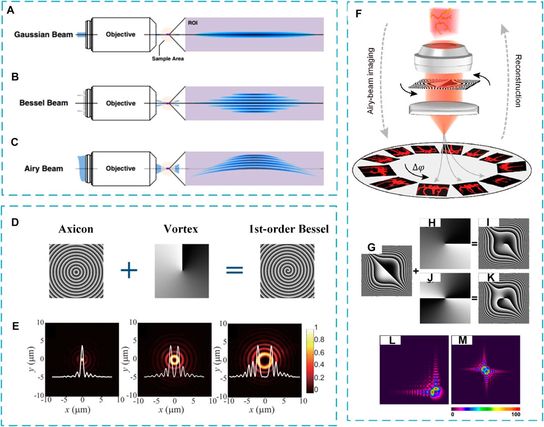
FIGURE 7. (A–C) Creation of (A) apertured Gaussian, (B) Bessel, and (C) optical Airy beams [80]. (D) Phase masks on the SLM and their superposition [81]. (E) Lateral beam profiles of the 0th-, 2nd-, and 4th-order Bessel beams [82]. (F) Principle of the Airy beam tomographic microscopy. The Airy beams of varying azimuthal angles illuminate the sample and tomographically reconstruct the sample structure using the recorded perspective images [83]. (G–K) Principle of the phase design of the vortex Airy beams [48]. (L,M) Simulated intensity distributions of single (L) and dual (M) vortex Airy beams [48]. Reproduced with permission from Springer Nature [82], reprinted with permission of OSA [80, 81, 83], and reprinted with the permission of AIP Publishing [48].
The non-diffracting Airy beam can be created by tailoring the fundamental Gaussian beam using a CPM [34]. The CPM in reciprocal space is defined as follows [86]:
where
where sgn is the sign function,
The binary Lee hologram is the fundamental algorithm to create the binary hologram. Other hologram algorithms include the dual-pixel complex modulation approach [90] and the superpixel method to tailor the complex field [91]. The phase response of each micromirror in the superpixel depends on the positions of the pixel on the DMD [79]. The response of a superpixel is the sum over the individual active pixels in the target plane. The responses of adjacent pixels inside the superpixel are
Nonlinear Generation of Non-Diffracting Beams
Apart from generating the non-diffracting beams only by linear diffractive elements, the nonlinear generation methods are also investigated for new wavelengths. For example, the generation of Airy beams with three-wave mixing takes place in nonlinear asymmetric photonic crystals. The researchers have generated an Airy beam through the second-harmonic generation and evaluated the tuning properties of the propagation dynamics and nonlinear interaction of the pump and second-harmonic output beams [14]. Efficient generation of a second-harmonic vortex and Hermite-Gaussian beams was reported recently in 3D lithium niobate nonlinear photonic crystals fabricated with a femtosecond laser [93].
For the frequency-doubling properties with 0th-order Bessel beam, phase-matched SHG in a KDP crystal takes place at angles usually inappropriate for phase matching [96]. In this respect, Bessel beams can be considered light beams with tunable wavelength. Specifically, the Airy vortex beam was generated in the nonlinear frequency conversion process when the fundamental wave with its phase modulated by an SLM is incident to a homogeneous nonlinear medium [94]. The parabolic trajectory of the Airy vortex beams can be adjusted by tailoring the phase of the fundamental wave (Figure 8A). Flexible tuning of non-diffracting beams in a two-dimensional nonlinear photonic crystal was realized through the interference of multiple non-collinear second-harmonic beams (Figure 8B) [95]. By manipulating the wavelengths of the beams and the angle of incidence of the fundamental wave, the arbitrary period, propagation length, and the wavelength of the generated nonlinear non-diffracting array beams can be tuned flexibly. These light beams can trap and manipulate multiple particles, create new forms of optical imaging systems, and act within nonlinear devices to bring novel functionalities to integrated optics.
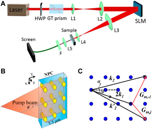
FIGURE 8. (A) Experimental setup for the nonlinear generation of Airy vortex beam. The sample is a homogenous 5-mol% MgO:LiNbO3 crystal for second-harmonic generation [94]. (B) Illustration of nonlinear non-diffracting array beam generation [95]. (C) Non-collinear quasi-phase-matching diagram [95]. Reproduced with permission from OSA [94, 95].
Features of Non-Diffracting Optical Beams
Although the propagation-invariant beams share common features, the physics of self-recovery of a non-diffracting beam is very clear under the dynamics of conical waves [37]. Most of the non-diffracting beams can be approximately generated from a conical superposition of plane waves. The non-diffracting beams convey infinite energy, a direct consequence of the non-diffracting feature [6]. Practically, the non-spreading beams are truncated by an aperture and tend to diffract with propagation. Thus, when the aperture size exceeds the spatial scale of the propagation-invariant field, the diffraction is “slowed down” during diffractive propagation [6]. This section introduces the major features of the non-diffracting beams, including the diffraction-free, self-healing, self-acceleration, phase singularity, and self-imaging properties.
Diffraction-Free Feature
The most prominent feature of the non-diffracting beams is the diffraction-free property. As the light beam propagates in free space, the beam would diffract with dimension broadening. For instance, the traditional Gaussian beam would increase the beam radius to
Self-Healing
Another important feature for the non-diffracting beam is self-healing. The caustic beams would be created by shaping the cylindrical wavefront with an axicon. Such a beam, once blocked by an opaque object, reappears at a certain plane with the same transverse intensity profile as that for an unblocked caustic beam [97]. Such a phenomenon is known as self-healing. Since the common non-diffracting beam is produced by the conical wave superposition, the parts traveling inwards will create outgoing conical waves through the axis reconverting the original transverse intensity profile. The diffraction perturbs the pattern at the early stage of the reconstruction but does not play a major role in the self-reconstruction. Self-healing implies that the beam is resistant against amplitude and phase distortions. The transverse beam profile disturbed by the non-transparent obstacle reproduces when freely propagating behind the obstacle. Such a feature is unique for the non-diffracting beams and has been corroborated with Bessel and Airy beams. The physics behind self-healing is the Babinet principle. Figures 9A–C show the experimental transverse profiles of the Airy beam with the major lobe blocked at the input (A) z = 0 cm, at the free-propagation distance of (B) z = 11 cm and (C) z = 30 cm, respectively. Apparently, the beam self-recovers to the traditional Airy profile after the partial block.
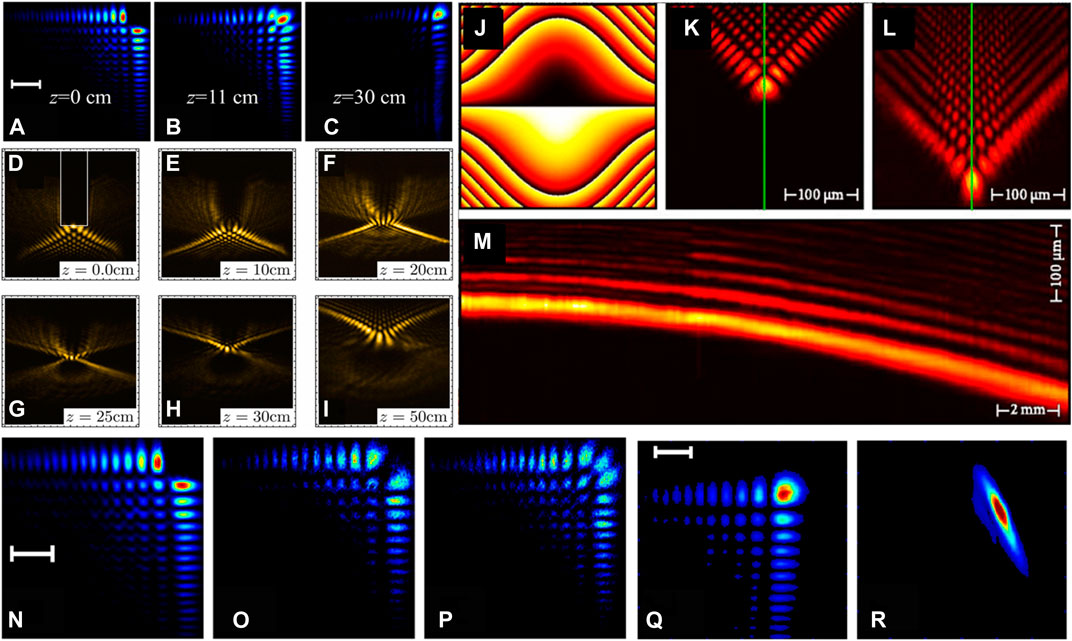
FIGURE 9. (A–C) Self-healing feature of the Airy beam with the main lobe obstructed. Intensity patterns at (A) the input z = 0, (B) z = 11 cm, and (C) z = 30 cm. (D–I) Self-healing of the Pearcey beam after an arbitrary perturbation. The obstacle was a cylinder, with the white line indicating the rectangular projection in (D). (J) Cubic phase pattern. Experimentally observed transverse distribution of Airy beam at the (K) front and (L) rear faces of a crystal. (M) Transversal acceleration. The green lines in (K,L) indicate the longitudinal section in (M). (N–P) Self-healing of an Airy beam in a scattering suspension of silica microspheres with 0.5 µm in diameter in pure water. Intensity patterns at (N) the input z = 0, (O) z = 5 cm, and (P) z = 10 cm. (Q,R) Propagation in a turbulent medium of (Q) an Airy beam and (R) the Gaussian counterpart. Reproduced from OSA [32, 98]. Reprinted from [28], with the permission of AIP Publishing.
Similar to the Airy beam, the Pearcey beam describes the diffraction of a cusp caustic with features similar not only to the Airy beam but also to the Gaussian and Bessel beams, i.e., auto-focusing, self-healing, and form invariance [98]. The Pearcey beam is described by the Pearcey function under the catastrophe theory, which deals with the diffraction of a cusp caustic and occurs as a 2D counterpart of the Airy function under the framework of the catastrophe theory. Although the Pearcey beam suggests auto-focusing during propagation, it still displays a self-healing feature [98, 99]. Figures 9D–I show the transverse profiles of the Pearcey beam at various locations (labeled on each panel). The obstacle was a cylinder placed at the initial plane labeled by the white rectangle (Figure 9D). The Pearcey beam self-reconstructs from the initial perturbation and then collapses and mirrors after its fundamental focus [98, 99].
Self-Acceleration
The non-diffracting Bessel beam assumes a straight propagation trajectory in free space. In contrast, the non-diffracting Airy beam self-bends in free space during propagation, similar to the parabolic trajectory of an object owing to gravity. Such self-bending property is also recognized as self-acceleration. In contrast to self-healing, self-acceleration can also be understood under the framework of catastrophe theory [100]. In many real applications, this bending feature would be considered a disadvantage. However, recent progress on super-resolution microscopy and multiphoton microscopy suggests that the bending freedom carries the information of the depth imaging [36, 81].
Figure 9J shows the typical CPM to shape the optical Airy beam with SLM. The beam profiles at the front and rear faces of the photorefractive crystal (SBN:Ce) are demonstrated in Figures 9K,L. The side-view profile shows a bent trajectory owing to the self-acceleration. The feature allows the induction of optical refractive index change and the waveguide inside the crystal [28]. The non-diffracting Bessel beam has been demonstrated unique application in volumetric multiphoton microscopy; however, it lacks the axial resolution of the structure in the volume [101]. Recently, the Airy beam has been intensively applied in fluorescence microscopy [11, 33, 102] due to its unique features of self-acceleration and free diffraction [6, 7]. The bending provides freedom to evaluate the axial location from the lateral shift originated from the structures in different sections. The Airy beam follows a projectile with self-accelerating trajectory; however, the accelerating trajectory could be made arbitrary in three dimensions by wavefront engineering using SLM [103–107]. The self-accelerating beam along arbitrary trajectory allows the design of self-accelerating beams with multipath multicomponent or periodic self-acceleration [108, 109]. The beams could also be radially and azimuthally self-accelerating [110, 111]. Those various forms of self-accelerating beams provide many possibilities to improve the existing challenges in biomedical applications.
The self-healing feature of the non-diffracting beam allows the propagation in the scattering and turbulent medium with the ability to preserve the shape [32]. Figures 9N–P show the Airy beam dynamics in the scattering medium of silica microspheres (n = 1.45) in water (n = 1.33), for which the main corner of the lobe was blocked (Figure 9N). The colloidal suspension was prepared with significant light scattering, sufficient to a granular feature when the beam propagates 5 cm in the silica-water mixture (diameter of 0.5 µm for silica) (Figure 9O). A complete reconstruction of the Airy pattern was observed in the same random media with a longer (10 cm) cell. Figure 9P depicts the self-healing feature of an optical Airy beam that propagates 10 cm in the same medium [32]. The Airy beam can also well preserve the shape in the turbulent medium. To verify the shape preservation in a strong turbulent environment, Figure 9Q shows the beam profile after propagation up to 8 cm above an aluminum foil heated up to around 300°F [32]. The resilience of the optical Airy beam in the absence of any initial wavefront distortion against turbulence was astonishing. In contrast, the traditional Gaussian beam deforms in shape significantly (Figure 9R). The robustness is qualitatively understood through the phase profile of the beam: change of the phase between 0’s and π’s results in null-intensity regions, and the singularities would be, on the contrary, extremely stable [32, 112, 113]. In contrast, the Gaussian beam heavily deforms and exhibits a rather distorted phase structure.
Self-Imaging
The coherent light with any transverse amplitude profile could be converted to the state with a periodical reconstruction. The non-diffracting propagation of the stationary wavefronts can also be produced in the pulse propagation. The non-diffracting beams exist in the temporal domain and present novel features, like self-imaging [114]. In contrast to the classical Talbot effect, pulse revivals with minimum temporal and spectral distortion feature the ultrashort-pulsed non-diffracting needle beams. The pulse transfer with high-fidelity ensures temporal and spatial multiplexing in the absence of nonlinear media, even at pulse durations as small as a few cycles [114]. A particular class of highly localized wave packets (HLWs) was recently introduced with temporally stable, radially non-oscillating ultrashort-pulse Bessel beams [115]. The spatiotemporally quasi-non-diffracting pulses propagate along the extended regions characterized by second-order autocorrelation with spatial resolution. Few-cycle wave packets resembling circular disks, rings, and bars of light represent the closest approximation of linear light bullets.
The self-image first could allow the non-diffracting beam to reproduce itself after a certain distance. This feature may bring a second advantage to propagate and transmit the image without spatial distortion. Self-imaging occurs in the coherent superposition of the non-diffracting beams if the propagation constants are conveniently coupled [114]. Such an effect expresses the spatial analog of the temporal mode-locking [57, 58]. Due to mode interference, the transverse intensity profile of the beam reappears (vanishes) periodically at the locations of the constructive (destructive) interference. Figure 10A shows the schematics of the non-diffracting Talbot effect. The intensity of propagation of sub-three-cycle needle beams at the fundamental wavelengths in the (B) absence and (C) presence of local phase distortion (left box, area of distortion) [114]. The temporal and spatial evolution of a few-cycle needle beam with a hexagonal pattern (period: d = 230 μm, a = 445 μm, SHG) are shown in Figures 10D–I, where the axial distance of dark rings in (D,E) is (L0+L1)/2 = 60 μm, and the diffractive patterns at (F,G) the first and (H,I) second non-diffractive Talbot distance [114].
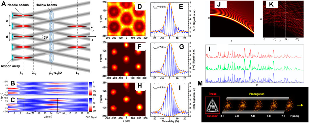
FIGURE 10. (A) Schematics for the non-diffractive Talbot effect [114]. (B) The intensity propagation of sub-three-cycle needle beams at the fundamental oscillation wavelengths (B) without and (C) with a local phase distortion (left box, area of distortion) [114]. (D–I) Temporal and spatial evolution of a few-cycle needle beam with a hexagonal configuration. (D,E) The axial distance of dark rings (L0 + L1)/2 = 60 μm, at (F,G) the first and (H,I) second non-diffractive Talbot distance [114]. (J–L) Airy-Talbot effect. The intensity plot of (J) 1D Airy beam and (K) sum of 20 Airy beams. (L) Linear intensity profiles at three planes of self-imaging,
The addition of Airy beams with non-identical phases exhibits the Airy-Talbot effect [116]. The 1D Airy beam suggests a self-accelerating trajectory (Figure 10J), while an addition of 20 Airy beams suggests that the Airy-Talbot effect is corroborated in the side-view propagation (Figure 10K). Transverse intensity profiles at three locations of self-imaging,
Biomedical Application With Non-Diffracting Waves
Biomedical applications of laser beams cover a broad area with a plethora of imaging, stimulation, sensing, and detection techniques. For instance, laser-scanning two-photon microscopy (TPM) [120, 121] has assisted the understanding of deep tissue events in neuron biology [122–125], owing to the deep penetration and high spatial resolution. However, a volumetric image of a 3D object in conventional TPM requires 3D raster scan, which inevitably decreases the volumetric frame rate. The slow frame rate brings about motion blur for in vivo imaging applications. Therefore, conventional TPM is insufficient for volumetric imaging in real time, such as recording the transient signal among neurons scattered in brain tissues. Non-diffracting beams with propagation invariance and self-healing offer excitingly novel features and functionalities in those applications, including multiphoton microscopy (MPM) [126], light-sheet fluorescence microscopy (LSFM) [11, 127], and optical micromanipulation [10, 27]. For instance, LSFM adopted a thin sheet of the light beam to excite the fluorescence, while orthogonal detection naturally ejects the out-of-focus information due to the absence of excitation light. Apart from eliminating the out-of-focus photons, the wide-field ability brings about a large FOV with the help of non-diffracting beams. Structures in biology are often buried deep inside the tissue, which inevitably scatters light and complicates microscopic imaging. Both the LSFM and the MPM benefit from the non-diffracting beam due to the ability of deep penetration, and lots of efforts have been put forward to improve the performance of various imaging modalities using the non-diffracting beams. In this section, we aim to summarize representative biomedical applications using non-diffracting beams.
Volumetric Multi-Photon Fluorescence Microscopy
The MPM is a powerful tool for recording the activity of neurons and neuronal networks in vivo through calcium transients. Traditional TPM scans the diffraction-limited spot across the sample. TPM performs better than traditional confocal microscopy in combating scattering and increasing the penetration, resulting from nonlinear excitation and longer wavelength illumination [121, 128]. In order to image the volumetric information, the excitation light has to be scanned in three dimensions to traverse the sample structure. The point-by-point scanning would increase the data acquisition time and thus slow down the frame rate. In real applications, the sample structure is sparse, and the point scanning results in an excessive scan that leads to a slow frame rate. The random-access microscopy localizes those specific structures and monitors the structure of interest but still requires scanning in three dimensions. The non-diffracting beam with the ability to preserve the shape over a distance much greater than the Rayleigh range provides perspective to increase the scanning speed, especially in sparse structure occasions, e.g., neurons. The hybridization of two-photon excitation and volumetric ability allows longer penetration depth while maintaining decent lateral resolution, which also greatly improves the localization of the lateral shift in the 2D projection of the volumetric microscope with Airy beam illumination. In 2018, two groups developed the three-photon microscopy (3PM) with Bessel beam excitation [101, 129, 130].
The axial depth (detection range) of traditional confocal and TPM microscopes is limited by the axial FOV. The volumetric imaging system often requires a large depth of field (DOF); to this end, the non-diffracting beam is capable of extending the FOV on the detection side. Proper choice of the extension length of the Bessel beam can be realized through the optical components, including the sample property and the single pulse energy. For highly transparent tissue, the long Bessel beam could illuminate the entire FOV, e.g., zebrafish [101]. The length could be physically configured by the optical components, e.g., the SLM or DMD. Moreover, the length should be adjusted to a shorter one for increased depth. The non-diffracting beams could improve the detection speed in MPM. The point spread functions (PSFs) of the 3PM (Figure 11A) and 2PM (Figure 11B) show needle-like structures and have been corroborated in the experiment (Figures 11C,D). The transverse cross-sections after integration of the Bessel beam along the z-axis suggest the fluorescence profile of the side lobes (E, 3PM; G, 2PM). Figures 11F,H show the experimental measurements. The images under Bessel 3PM and 2PM are compared in Figures 11I–L, where the rectangular regions in Figure 11I are zoomed in (J) and (K). Figure 11G shows the schematic layout of the hybrid 2PM and 3PM combined with traditional TPM and MPM [101]. The 3PM adopts a non-collinear optical parametric amplifier (NOPA, Spectra-Physics) pumped by a high-power 1,040 nm femtosecond laser. The NOPA produces 50 fs pulses with an average power of 500 mW at 1,300 nm and a 400 kHz repetition rate. Another custom-made femtosecond Nd: fiber laser at 930 nm delivered up to 800 mW 150 fs pulses at a 50 MHz repetition rate act as the excitation source for 2PM. Both beams were combined and steered using a pair of scan mirrors (6215H, Cambridge Technology) [101]. Typically, a water immersion objective (×25, NA 1.05, Olympus) focuses the light into the sample. The epi-fluorescence was detected by a GaAsP PMT detector (H7422p-40, Hamamatsu) through a long-pass dichroic mirror (FF735-Di02-25 × 36, Semrock). A condenser lens, a short-pass filter (ET770sp-2p, Chroma), and a 525/40 nm bandpass filter (FF02-525/40-25, Semrock) were used to collect and filter out the fluorescence signals [101]. It is noteworthy that the setup in Figure 11G is just an example to realize the MPM with volumetric imaging ability.
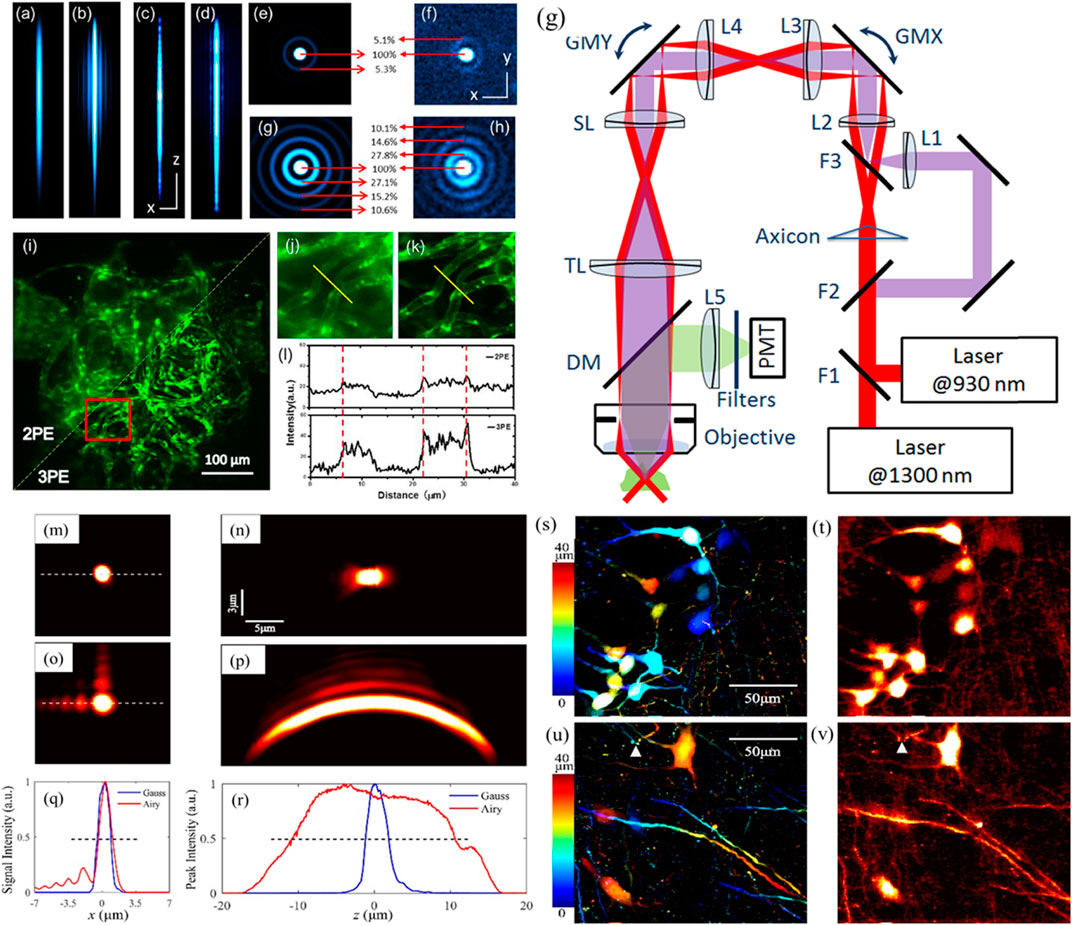
FIGURE 11. (A,B) Theoretical PSFs of 3PM and 2PM in the x-z plane. (C,D) the experimental PSFs. Scale bars: z, 100 μm; x, 2 μm. (E,F)x-y cross-sections from the integration of the z-axis of the Bessel beam to simulate the fluorescence profile of the side lobes (E, 3PM; G, 2PM). (F,H) Experimental results. Scale bar, 2 µm. (I–L) Blood vessels in live zebrafish under Bessel 3PM and 2PM. (I) An example of the fish under Bessel 2PM and 3PM and the region in red box are zoomed in as (J,K). (L) Fluorescence profiles along the line across the same blood vessels. (G) Schematic diagram of the apparatus. F, flipper mirrors; Axicon, α = 2°; L, Lenses; SL and TL (200 mm). Multiple conjugate planes were created onto the back focal plane (BFP) of the objective. Galvo mirrors: GMX/GMY, for beam scanning in the x/y direction. DM, dichroic mirror. Images of 1 μm fluorescent sphere under (A,B) Gaussian and (C,D) Airy TPM. The (M) lateral and (N) axial PSFs under Gaussian mode. The lateral (O) and axial (P) PSFs under Airy mode. (Q) Lateral intensity distribution in (M,O). (R) Maximum intensity with respect to the axial direction for (N,P). Blue lines, Gaussian beam; red lines, Airy beam. (S,U) Projection of image stack of a mouse brain slice with depth coded by color. Step size: 0.5 μm. (T,V) Single volumetric frame of mouse brain slice captured with Airy TPM. Reproduced with permission from OSA [24, 101].
Since the areas of both MPM and volumetric imaging are highly developing, there will be many hybrid designs along the direction despite many versions having been demonstrated already. For instance, the combination of a Bessel module and a two-photon mesoscope has been demonstrated for the imaging of volumetric neural activity on the mesoscale with a synaptic resolution while maintaining the ability to resolve synaptic structures such as dendritic spines and axonal boutons [84]. The MPM with a non-diffracting beam has a direct impact on neuron science. Both individual neurons and neural networks extend over hundreds to thousands of microns in 3D. Visualizing neural circuits over large tissue volume at subcellular resolution and high speed is challenging due to the light scattering and slow scanning [131]. The fast volumetric ability enables rapid calcium imaging of entire dendritic spans of neurons and neural ensembles within multiple cortical regions in the awake mouse brain. An axially extended excitation region is steered in 2D to project the view of the volume defined by the scanning area and the axial extent onto a 2D image [131]. The Bessel-like focus provides subcellular resolution at exactly the same volumetric imaging rate as the 2D scan. The produced Bessel-like focus has an adjustable axial full width at half maximum (FWHM) from 37 to 116 µm. The volumetric ability makes it possible to record the calcium activity traces by transients highly synchronized in dendrites and soma. The synchronized transients in spines and dendrites suggest faster dynamics than those in the soma. In some spines, transients independent of the synchronized events were also detected, preferentially evoked by local synaptic inputs [131].
The MPM with non-diffracting beams has been applied in neurobiology by imaging calcium dynamics in volumes of neurons and synapses in mice, zebrafish larvae, and fruit flies in vivo. Calcium signals in objects, e.g., dendritic spines, could be resolved at video rates [131]. The non-diffracting beam makes it possible to record all the calcium transients in the volume with video-rate, even using the calcium indicators with limited brightness. In in vivo experiments, the locations of neurons and their synapses remain unchanged during the imaging session and there is no need to monitor and track their locations continuously in 3D. Therefore, Bessel beams excite 3D volumes via extended DOF [131]. For sparsely labeled brain tissues with a minimum structural overlap in the 2D projections, the neural activity in the volume can be monitored with a frame rate equivalent to the 2D rate. A single neuron receives multiple synaptic inputs and traverses millimeters to send over projections [131]. Through the long-range connections, the information goes through multiple cortical regions to transmit signals. It is important to record neural activity through cortical depth over a large volume at subcellular resolution. The two-photon fluorescence mescoscope with 5 mm FOV and volumetric module with Bessel focus has been demonstrated for the rapid mesoscale volumetric imaging of the neural activity in mouse brain in vivo [131].
Although the Bessel beam has been demonstrated in volumetric imaging of neurons, the self-accelerating Airy beam is also interesting in the TPM [24]. The Airy beam shares the benefit with the Bessel beam to increase the acquisition speed by projecting the axial information onto a 2D image [101, 129, 130, 132, 133]. Moreover, the self-acceleration feature brings new possibilities that go beyond the Bessel beam. Toward this end, a broadband femtosecond fiber laser with a central wavelength of 1,065 nm (30 MHz repetition rate and 180 fs pulse width) was converted into a spatial Airy beam. The spectrum modulation with a CPM corresponds to a pupil function:
where
The advantage of the Airy beam has been demonstrated in the two-photon imaging of the Thy1-YFPH (B6.Cg-Tg(Thy1-YFP)HJrs/J, the Jackson Laboratory) mice at the age of 2 months. Brain samples were sectioned by vibratome to about 40 μm thickness and postfixed in PFA overnight. The two-photon fluorescence image of the tissue is shown in Figures 11S,U by scanning the tissue layer by layer, where the color encodes the axial coordinate. Within the FOV, the neurons at different depths in the tissue can be recognized. The Gaussian scan at an individual axial location only visualizes a sparse subset of these neurons. In contrast, all the neurons can be simultaneously visualized in a single volumetric frame under the Airy mode (Figures 11T,V). Although the volumetric image is slightly blurred owing to the side lobe, the details in the neuron, like the axons and dendrites, can still be identified with good resolution (Figure 11S). Due to the long focal length of the Airy beam, the axial range is sufficient to cover all the structures in the whole tissue slice. The axons may not align in the transverse plane, and the Airy beam with extended focus may image the whole structure of the axon, which is not possible under Gaussian illumination. The non-diffractive nature of the Airy beam can also provide higher resolution and SNR than traditional confocal microscopy in imaging fluorescent objects immersed in turbid media [134].
It is of great importance to design head-mounted MPM for deep cortical layer neuronal imaging in a freely moving animal [135]. With advanced fiber optics, we envision that the non-diffracting beams would deliver high-energy non-diffracting pulses tailored to in vivo applications. In contrast to the straight Bessel focus, the focus of the Airy beam self-accelerates and provides a bent PSF. This is somehow non-ideal for the volumetric imaging as the SNR may be affected by the side lobe in the TPM. However, the Bessel focus innately combined the axial information by projecting all the structure in the volume onto a single 2D image and the Airy beam may provide the potential to distinguish the axial information according to the bending magnitude and has been verified in single-molecule localization super-resolution microscopy [36]. The Airy beam is also able to image structure under deep penetration [134]. The axial resolution of the Airy beam would be introduced in Axial Resolution in TPM With Self-Accelerating Beams.
Light-Sheet and Raman Microscopy With Non-Diffracting Beams
LSFM adopts a planar illumination beam to excite the fluorescence in a thin layer of the sample, with the thickness determined by the numerical aperture of the excitation objective. LSFM eliminates the out-of-focus fluorescence light by only illuminating the sample with a thin light sheet normal to the detection axis of the microscope. However, the traditional Gaussian beam provides a smaller FOV along the beam propagation direction owing to diffraction. As a result, the normal illumination beam suffers from diffraction broadening; thus, the thickness varies along the beam propagation. Therefore, a uniform magnitude of size upon propagation is ideal for light-sheet illumination. Moreover, the non-diffracting beam features shape-preserving for a distance much longer than the Rayleigh distance, offering the ability to extend the illumination FOV in the LSFM application [11, 136]. The Bessel focus TPLSM allows volumetric imaging of neurovascular dynamics while preserving the high lateral resolution and multi-color capability [25]. With the advancement of bright and efficient two-photon fluorescent sensors, Bessel TPLSM simultaneously images neuro-vasculature with neurons and glia to produce a high-throughput database for unveiling the dynamics of neurovascular in normal and diseased brains.
In volumetric LSFM, the axial detection range is crucial to improving speed [137, 138]. On this occasion, the non-diffracting beam helps to extend the detection range, e.g., the Bessel and Airy beams, owing to the shape-preserving feature. The experimental configurations of the LSFM could be found in many review articles, while the non-diffracting beams have also introduced in [139, 140]. The fluorophore outside the excitation volume would not be excited, greatly reducing the noise thanks to the out-of-focus excitation. LSFM in single- and two-photon modalities has been a powerful, low-photodamage, wide-field microscope for fast volumetric imaging of biological tissue. The 2-week posthatching (wph) larva of the FLT4-EGFP zebrafish strain expresses EGFP in the lymphatic endothelial cells, with angiography labeled by dextran-conjugated tetramethylrhodamine B being imaged with LSFM (Figure 12A) [136]. The 3D reconstruction of the entire fish clearly shows the vascular system of the zebrafish larva. The blood vessels in red show the morphology of the dorsal aorta, dorsal longitudinal anastomotic vessel, posterior cardinal vein, capillary blood vessels, and intersegmental vein and artery. This ability makes it possible to study the organ interaction in the entire fish.
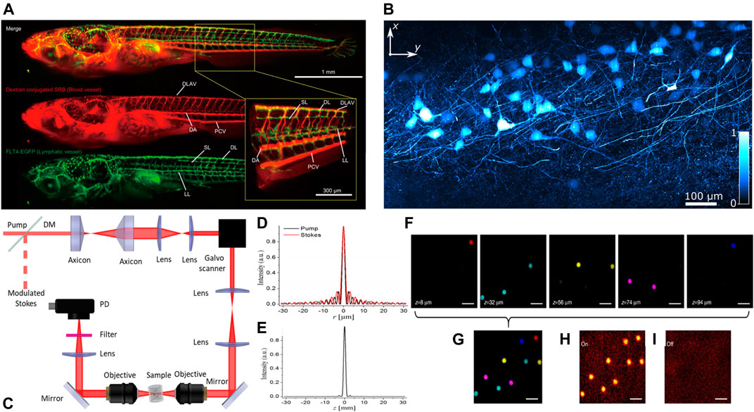
FIGURE 12. (A) Entire body imaging of Medaka larvae using the dual-color LSFM. 3D reconstructed view of the lymphatic and blood vessels in the entire body in a 2 wph larva. Green represents the EGFP signals from the FLT4-EGFP transgenic strain, and red demonstrates the dextran-conjugated rhodamine signals from the blood vessel. Yellow rectangular illustrates a magnified view at the body trunk [136]. (B) Maximum intensity projection of Thy-1 GFP-expressing mouse brain tissue, using the two-photon planar Airy light-sheet [127]. (C) The experimental setup for the stimulated Raman projection (SRP) microscopy. (D) Linear profiles of the pump and Stokes beams, (E) the SRP signal produced by the ring-overlapping Bessel beams, (F) the SRS imaging of polystyrene beads located at different depths by Gaussian beams SRS microscopy, and (G) the volumetric image by SRP microscopy with Raman resonance (H) on and (I) off. Reprinted with permission of OSA [127]. Reproduced from Springer Nature [26, 136].
Although the Airy beam has been demonstrated in the LSFM, the self-bending PSF introduced image inhomogeneity [11]. A recent advancement makes the use of planar Airy beam to provide isotropic performance without image deconvolution [127]. This takes advantage of the shape-preserving feature to extend the FOV while keeping a flat field using the self-accelerating beam (Figure 12B). The LSFM could also perform under either single or multiple photon modes by switching different laser lines [127]. Such a symmetric planar Airy beam not only improves the SNR but also minimizes the use of deconvolution during image processing. Light-sheet microscopy combines unparalleled image contrast and minimal exposure with high resolution, thus alleviating the photo-bleaching and photo-toxic effects. The non-diffracting Bessel and Airy beams illuminate the full FOV uniformly but have transversal side lobes that would result in poor axial resolution [127]. The planar two-photon Airy light-sheet was explored to achieve a minor modification to a single-photon light-sheet microscope and improved SNR performance [127]. In practical LSFM experiments, one has to spend efforts to fix different kinds of samples, e.g., embryo and brain tissues. The samples in the LSFM are usually soft and could be embedded in the agarose gel. Recently, ultrasound confinement was proposed to hold the sample without mechanical touch [141]. These advancements make the light-sheet imaging easier to operate and data acquisition more precise.
The LSFM was further extended to 3PM with enhanced penetration depth [142]. The potential advantages in 3PM light-sheet microscopy enhanced by propagation-invariant Bessel profile in preference to Gaussian beams include the augmented SNR and longer penetration depth. The propagation-invariant Airy beam allows a tenfold increase in FOV for a single-photon excitation microscope [11]. The characteristic asymmetric distribution of the traditional Airy beam restricts the application in multiphoton excitation. 3PM has been increasingly used to record neural activities beyond the typical depth of two-photon imaging modality [143]. With the assistance of the non-diffracting beams, the MPM would perform better for in vivo imaging of biological tissue, especially the mouse brain, with improved SNR and penetration depth. 3P fluorescence imaging excited with an axially extended Bessel focus has been applied to image mouse brain slice and in vivo imaging of the mouse brain [130].
Coherent Raman scattering (CRS) microscopy is a well-known nonlinear Raman microscopy that performs fast label-free imaging of the chemical bonds of molecules. However, traditional CRS microscopy using point-by-point scanning restricts the speed of 3D imaging. Volumetric imaging with non-diffracting beams enables rapid and deep measurements of 3D structures with decent lateral resolution through a 2D lateral scan. Chen et al. [26] have demonstrated that the stimulated Raman projection (SRP) microscopy with Bessel beam allows high-speed volumetric chemical imaging. In their demonstration, two synchronously produced pulsed lasers from the same oscillator (InSight DeepSee, Spectral Physics) at a repetition rate of 80 MHz served as the pump and Stokes beam. The wavelength of the Stokes beam is fixed at 1,040 nm. The tunable pump beam had a wavelength from 680 to 1,300 nm. Two axicons (AX2520-B, Thorlabs) converted the overlapped Gaussian beams into doughnut-shaped beams (Figure 12C). The doughnut-shaped beams were steered by a 2D galvo system (GVS012, Thorlabs) and were transferred to a microscope objective to create Bessel beams. Although the signal from the rings of the Bessel beams may bring the interfering signal, the different intensity distribution of the pump beam and the Stokes beam minimizes the partial overlap of the rings, which makes the interference SRP signal from the ring-like sidelobes much smaller than the signal generated from the central major lobe (Figures 12D,E).
For the proof-of-concept experiment, polystyrene microspheres dispersed and fixed in a 3D matrix of agarose gel were imaged by both traditional CRS and SRP modalities [26]. Under traditional Gaussian mode (Figure 12F), the SRS microscopy can image the microspheres plane by plane. In contrast, the SRP microscopy acquires all the spheres at the same lateral location through only a single 2D scanning (Figure 12G). For example, they tuned the Raman transition to
Improve the Transverse Resolution of Two-Photon Microscopy With Bessel Beams
The resolution of TPM is often limited by the excitation wavelength, which is usually on the order of ∼1 μm. The resolution is determined by the PSF of the excitation beam with
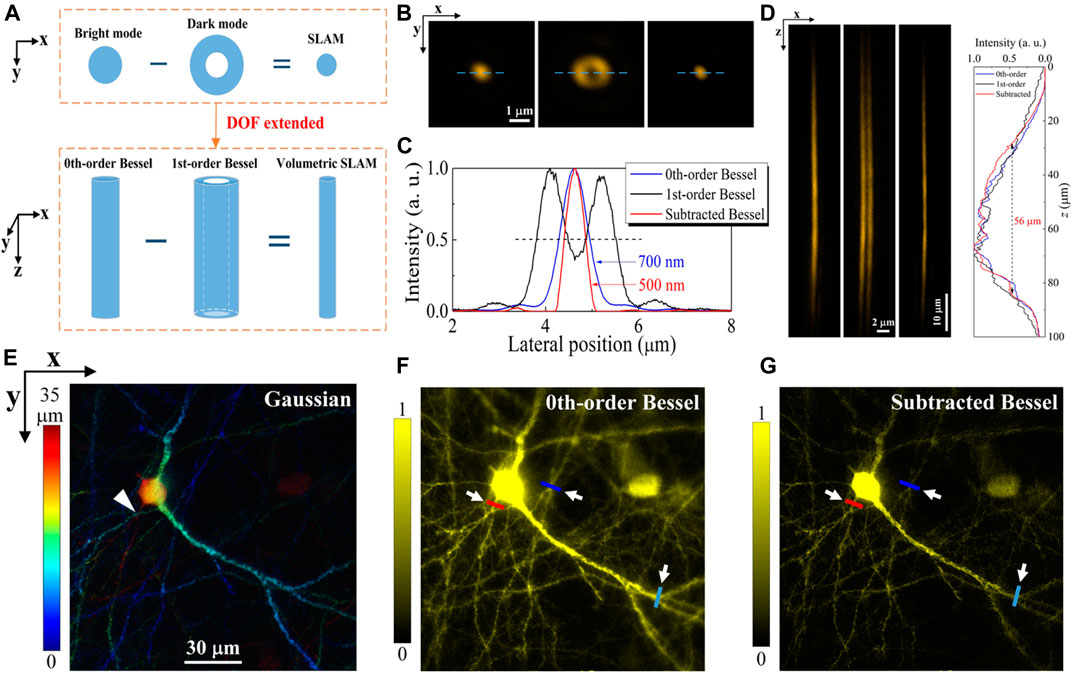
FIGURE 13. (A) Mechanism of the conventional SLAM (top) and the v-SLAM (bottom). (B) The lateral intensity distribution of the 0th-order Bessel (left), the 1st-order Bessel (middle), and the subtraction of Bessel beams (right). (C) Linear profiles of the PSF in (B). (D) PSFs of the 0th-order, 1st-order, and subtracted Bessel beams in the x-z plane. (E) Projection of the Gaussian-scanned image stacks for the mouse brain slices (color codes the depth). The images are obtained by the 0th-order Bessel beam (F) and the subtraction image (G). The three positions with different depths (
The concept of SLAM was initiated by Dehez et al. [144] to enhance the resolution and image contrast in scanning microscopy. The SLAM takes advantage of the image subtraction between the bright and dark modes and exploits the smaller size of the dark spot of the transverse laser mode. The advantages of SLAM microscopy are its applicability to diverse imaging platforms and sample types. Previous SLAM was applied in the 2D plane on the tight focus [145–149]. In order to use the SLAM concept for the DOF extension microscopy in 3D, a pair of needle-like beams with the bright and dark mode allows the subtraction for transverse resolution enhancement in volumetric imaging.
The Bessel beam has been used to extend the DOF in 2PM imaging of neurons [133]. However, the intensity profile of the 0th-order Bessel beam suggests strong side lobes under two-photon excitation (2PE) that generates a noisy background and decreases the SNR. Because 2PE (3PE) fluorescence takes the cubic (quadratic) dependence on the excitation power, the PSF with a Bessel beam under 3PE has much smaller side lobes than that under 2PE. The Bessel beam 3PM has been demonstrated both theoretically and experimentally in simultaneous calcium imaging of brain tissue at different axial locations in live fruit flies and rapid volumetric imaging of neuronal structures in live mouse brains [101, 129, 130]. The results highlight the special advantage of performing rapid volumetric imaging with an enhanced SNR in deep brain tissue in vivo using Bessel 3PM.
The multiple orders of Bessel beam are also utilized to increase the imaging contrast and resolution. The most commonly used Bessel beam is the 0th-order Bessel beam, whose lateral intensity profile displays a bright central spot surrounded by many concentric rings (side lobes) with decaying energy. The performance of the Bessel beam TPM mainly counts on the excitation from the bright center spot due to its dominant intensity. In contrast to the bright center, the side lobes are redundant and contribute mainly to the image background due to their substantially high energies. The lateral profile of the 3rd-order Bessel beam is found to well inhibit the side lobes of the 0th-order Bessel beam, which is ideal to conduct the image subtraction for cancelling the image background introduced by the side lobes of the 0th-order Bessel beam [85]. On the other hand, the 1st-order Bessel beam is also employed to enhance the lateral resolution over the extended DOF of the 0th-order Bessel beam. The conventional method of SLAM in 2D is extrapolated to 3D. The v-SLAM is a counterpart of the 2D SLAM. As a result, the equivalent beam in v-SLAM is a much thinner needle beam produced from the subtraction from the straw-like 1st-order Bessel beam. In contrast to the 0th-order Bessel beam, the transverse resolution for the v-SLAM increases by 28.6% and preserves over the axial depth of 56 µm.
Recall that the Bessel beams are described by Bessel functions, which originate from a set of solutions of the free-space Helmholtz equation [3]. The azimuthal phase term in the electromagnetic field of the high-order Bessel beam displays a phase singularity at the center, creating a straw-like beam [66, 150]. The transverse profile of the beam is an invariant doughnut pattern, which is similar to the vortex beam, such that the high-order Bessel beam can be understood as a dark beam and paired with the needle-like 0th-order Bessel beam (bright mode) to perform the subtraction. Furthermore, the 0th-order and high-order Bessel beams have equal axial depth, avoiding an excessive resolution enhancement and ensuring an appropriate subtraction over the whole beam length.
To create different Bessel beams, the phase of the excitation beam is modulated by the SLM. The Bessel beam has an electric field in the cylindrical coordinate as follows [150]:
where
Figure 13A shows the concept of the conventional SLAM and the V-SLAM. Adopt the conventional SLAM in 3D, non-diffracting vortex beams with multiple orders extending the DOF such that the SLAM is extrapolated to 3D. Both the 0th-order and the 1st-order Bessel beams have axially elongated profiles and maintain invariant lateral size. The major difference is that the 0th-order Bessel beam is a concrete needle-like beam with a lateral Bessel shape, while the straw-like 1st-order Bessel beam laterally shows a doughnut shape. The subtraction of the straw-like beam from the needle-like beam generates a thinner needle-like beam; thus, the equivalent lateral resolution is enhanced over the entire DOF.
The PSF of the Bessel TPM has been evaluated by scanning a single fluorescent nanosphere (100 nm, F8800). Figures 13B,C show the transverse fluorescence profiles under the illumination of the 0th-order (solid spot) and the 1st-order doughnut-shaped Bessel beams and the subtracted PSF in sequence. The 0th-order and 1st-order Bessel beams act as the bright and dark modes, respectively. Therefore, the subtracted PSF is as follows [144]:
where g is an empirical subtraction factor. A large value of g contributes to a better lateral resolution; however, it also introduces artifacts with negative pixel values, which deteriorate the image quality. The subtraction factor is usually limited to 0.5 ≤ g ≤ 1. The red line in Figure 13C shows the PSF with enhanced resolution, where a small portion of negative pixel values was truncated to 0.
PSFs of the 0th-order, 1st-order, and subtracted Bessel beam are shown in Figure 13D. The FWHMs of the 0th-order and the subtracted Bessel beams are 700 and 500 nm, respectively. The resolution can be further improved with a large g depending on the balance with image deterioration. In contrast to the 0th-order Bessel beam, the transverse resolution in v-SLAM increases by 28.6% and preserves over the 56 μm axial depth. The axial resolution enhancement is evaluated by shifting two adjacent fluorescent microspheres along the axial direction, and imaging performance was also tested using a 50 μm thick mouse brain slice. The mouse expresses the yellow fluorescent protein (YFP) in layer-V pyramidal neurons (Thy1-YFP H-line). The mouse brain slice was scanned layer by layer under Gaussian illumination with a step of 0.5 µm. Figure 13E shows the color-coded stack of the projected images. In contrast, the zeroth-order Bessel beam shows a volumetric image using a single 2D scan (Figure 13F). The subtracted image in Figure 19G shows a clearer image for the subcellular structure. The contrast enhancement intrinsically comes with the SLAM since the negative values near the edges are forced to zero [144].
Axial Resolution in Two-Photon Microscopy With Self-Accelerating Beams
MPM with extended DOF has been demonstrated extensively in stimulated Raman, two-photon, and three-photon excitation microscope in neuroscience applications with fast frame rate [26, 84, 133, 151]. Both the non-diffracting Bessel and Airy beams could extend the DOF inside the scattering sample and have been demonstrated in the two-/three- photon microscope. The non-diffracting beam with elongated axial focus extends the axial FOV but sacrifices the axial resolution [101]. The PSF for the Bessel beam shows a straight light needle along the propagation [101, 130]; in contrast, the Airy beam presents a curved PSF [24, 87]. Although the two beams offer isotropic transverse resolution at all depth locations within the volume [133], the bending PSF poses the possibility of dissecting the axial information.
Volumetric microscopy provides improved speed under confocal mode for sparsely labeled samples. Instead of a layer-by-layer scan across the 3-dimensional (3D) volume [120], a volumetric microscope projects the volume onto a single 2D scan. Volumetric microscope with Bessel beam possesses axially elongated needle-like intensity [101, 130, 133] but lacks the axial resolution. With the self-accelerating Airy beam, it is possible to image the volume and resolve the structure axially. The self-accelerating Airy beam bends itself, leading to a non-perpendicular projection of the volume in TPM. Such self-acceleration can be utilized to localize single molecules for ultrahigh-resolution microscopy [36]. The association of the bending PSF and the axial depth allows the dissection of the axial location using the bending magnitude. Additionally, the Airy beam provides a more extended axial range in contrast to the Bessel beam. A pair of Airy beams with opposite self-bending directions was applied to scan the volumetric sample in sequence under two-photon microscopy to map the axial position [87]. For densely distributed structures, a data processing algorithm is required to reconstruct the 3D volume from the 2D projections using mirrored Airy beams. This approach was corroborated to achieve high accuracy in 3D localization over an extended axial range and is appropriate for continuous and dense structures. The advantages of the volumetric TPM with an Airy beam over Bessel beam TPM and conventional Gaussian TPM are the depth resolution and less scanning times, respectively.
Figure 14A illustrates the principle of depth-resolved volumetric microscopy with SABs. The CPM is adopted to convert the fundamental Gaussian beam to an Airy beam. The beam goes through an objective lens and forms the Airy-like focus. This axially elongated Airy beam (Figure 14C) excites the two-photon fluorescence in the volumetric sample. A paired Airy beam with the CPM rotated by 180° in the same plane (Figure 14D) provides another set of fluorescence images. The paired Airy beams bend toward opposite directions as confirmed from the PSF mapped with a single fluorescent microsphere (Figures 14C,D). The insets in Figures 20C,D show the corresponding CPM displayed on the SLM. Due to the self-bending feature of the Airy beam, the relative lateral locations of the SABs are depth-dependent. Since the CPM for producing Airy beam is anti-symmetric, i.e.,
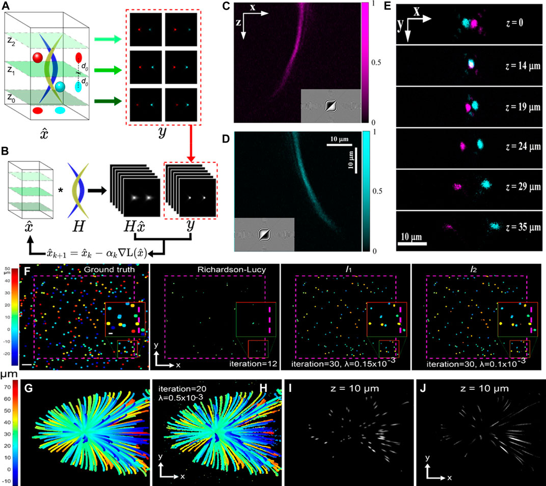
FIGURE 14. (A) Images are collected at multiple planes in sequence using Airy beams with reversed bending. Although the magnitudes of lateral shifts for the two spheres are nearly identical for images taken at
The response of an optical instrument is assumed to be shift-invariant, and the collection of signal
Consider a discretization model that
The implementation of MABs requires tedious calibration to extract the depth information, which complicates the volumetric imaging of the dense sample. It is challenging to reconstruct the 3D volume from a 2D image scan [24, 154]. Since only the 2D images in the real application are acquired, a loss function that evaluates the difference between the observed image
with minimization condition,
where
with
respectively.
Figures 14F–G show the data processing with the image reconstruction algorithms. Sample images of 1 μm fluorescent beads scattered in the volume were numerically generated using MABs with an axial FWHM of 20 μm. The Richardson–Lucy deconvolution shows a much shorter effective axial extension than
Depth Extension and Signal-Noise-Ratio Improvement in Microscopy
The non-diffracting Airy beam has been applied in many types of fluorescent microscopes, including the MPM and the light-sheet fluorescent microscopy [10, 83, 87, 159]. For the MPM, normally, the excitation and detection share some common paths in the objective and the non-diffracting beam shaping unit (axicon or the CPM) could be in the common path. Non-diffractive beams are generally applied in the volumetric MPM as the excitation beam owing to the isotropic resolution at all depths in the sample [133, 151]. However, in the LSFM [137], the detection path is orthogonal to the excitation path, and the non-diffracting beam shaping unit could be in the detection path to extend the detection depth.
The extended DOF of the non-diffracting beam is made possible by spreading the focus in the axial direction and will reduce scanning time for the MPM. However, the lateral resolution is degraded as compared with the TPM using the traditional Gaussian beam. Additionally, longer non-diffracting length results in a much worse lateral resolution [130]. Therefore, it is required to increase the transverse resolution over the extended DOF for volumetric imaging. As the Airy beam bends in spatial domain with the self-accelerating feature, the Bessel beam with straight propagation traces would extend the DOF in the fluorescence microscopy.
The DOF extension results in less scanning to probe the whole volume by spreading the focal spot axially. The non-diffracting beam serves as an excitation beam in rapid volumetric imaging microscopes. The increase in DOF of a traditional microscope is associated with the reduction in NA and the resolution [153]. Dowski and Cathey [160] have first reported that the asymmetric PSF produced by a cubic phase encodes the image with an extended DOF in the digital recovery without sacrificing the resolution. Volumetric images in the conventional microscope are generally degraded by defocus-induced artifacts. One possible way to minimize the artifact is to determine the spatially variant translation of the image components to compensate for the defocus [153]. This enables the reconstruction of artifact-free, extended DOF images with a 2D defocus.
Multiphoton fluorescence microscopy with an extended and reconfigurable DOF improves the temporal resolution for volumetric imaging of the thick sample. Figure 15 shows the difference of the longitudinal PSFs of the Gaussian and Bessel beams [133]. The axial length of the Bessel beam is generally dozens of times that of the Gaussian beam, which allows fewer scans to probe the entire volume of interest. The axial length of the Bessel beams is also adjustable by controlling the width of the incident Gaussian beam on the axicon (Figures 15C,D), making the Bessel beam flexible for samples of different thicknesses.
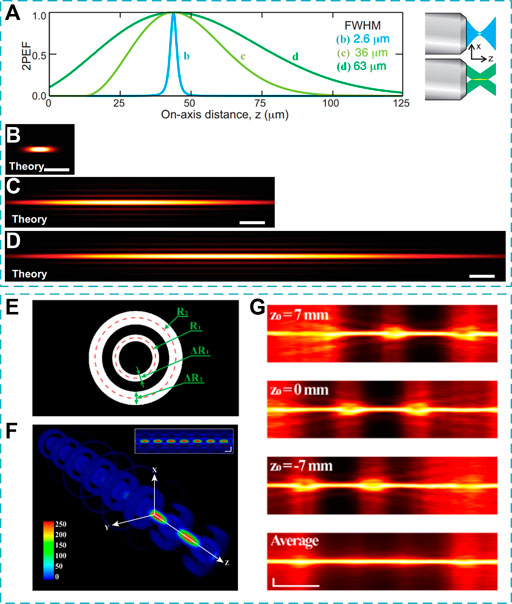
FIGURE 15. (A–D) Longitudinal PSFs of Gaussian and Bessel beams [133]. (A) Two-photon fluorescence along the longitudinal axis for an extended DOF setup (green) in contrast to a conventional setup (blue) with identical transverse resolution. (B) Theoretical PSF in the longitudinal plane with a standard DOF setup (Gaussian beam width = 2.7 mm). (C,D) Theoretical PSF with extended DOF, where the incident Gaussian beam width on the axicon is (C) 0.27 mm and (D) 0.47 mm. Scale bars, 5 μm. (E) Illustration of the double-ring phase pattern on SLM, with two concentric rings of finite width ΔR1 and ΔR2 [23]. The dashed circles demonstrate the average radii of the ring. (F) Perspective view of a 3D double-ring phase beam. Inset shows the side-view of the beam. Scale bars: 400 nm. (G) Side-view profiles of positively translated (z0 = 7 mm), original (z0 = 0 mm), negatively translated (z0 = −7 mm) double-ring PSFs, and the average of all the three PSFs. Reproduced from OSA [23, 133].
A side effect of using the non-diffracting beam for depth extension in fluorescence microscopy is the side-lobe-induced imaging background. Although the background is not significant in general applications, it is non-ignorable in some cases, such as using the high-NA objective for a better lateral resolution [85]. Researchers have tried several methods to eliminate the side lobes in imaging systems for a better signal-to-noise ratio (SNR). The combination of the Bessel beam and the three-photon excitation was confirmed to increase the SNR in the 3PM, owing to the higher-order nonlinearity in the 3PM than that in the 2PM [101, 130]. The axial superposition of two Bessel beams for a 0th-order Bessel beam was also demonstrated in fluorescence microscopes using beams interfered with specific conical wave vectors [23, 161]. The interfered Bessel beam is produced by creating two concentric annular apertures (Figure 15E) [23]. The radii and thicknesses of the two annuli are determined by varying SLM phase patterns for optimized performance. In contrast to a single Bessel beam, the interference of the two Bessel beams of different orders leads to a remarkable spatial alternation of sequential bright and dark regions along the axial direction (Figure 15F). By computationally averaging the three DRiP beams in 3D, it exhibits an axially uniform PSF, maintaining a high transverse resolution throughout a substantially extended DOF (Figure 15G). The method of PSF subtraction is also used for the SNR improvement because the lateral rings of the 3rd-order Bessel beam matched well with the side lobes of the 0th-order Bessel beam, such that the image acquired by the 3rd-order Bessel beam is considered as the background of the two-photon image scanned with 0th-order Bessel beam [85]. The deconvolution, as a complementary way, cancels the side lobes of the non-diffracting beams [162].
Conclusion
In conclusion, the non-diffracting beams were studied in the physics community on the fundamental physics, generation methods, and various forms. Due to the advanced technologies in spatial light modulation, the non-diffracting beams have found numerous applications. In this review article, we started from the fundamentals in non-diffracting beams, followed by the generation and biomedical applications of the non-diffracting beams. In general, the non-diffracting beams are an important family of spatial optical modes that can combat the scattering and penetration in biomedical imaging occasions. In terms of the application aspect, we mainly focus on biomedical engineering, including fluorescence microscopy, two-photon microscopy, label-free Raman microscopy, and optical non-invasive manipulation of biological cells.
The above applications of the non-diffracting beams are just a few representative examples in most recent years. This also suggests that the unique features of non-diffracting beams can benefit many applications in biomedical optics. Such field is still developing, as the non-diffracting beams can also be applied in many studies, for instance, to homogeneously induce the photonic nanojet on the dielectric microparticles with enhanced backaction force against the photon flux [163] and to excite the fluorophores in the nonlinear optical microscope for multi-photon or high-harmonic generation. All in all, we anticipate that the non-diffracting beam will continue to contribute to many of the biomedical application researches to overcome the light scattering and large penetration drawbacks. With the recent advances in metasurface design [164] and fabrication of optical fiber, it is possible to integrate the non-diffracting beam with optical fiber for easy delivery of the non-diffracting beam [165]. With the non-paraxial beams, it would be possible to further improve the axial resolution of the MABs in the volumetric two-photon imaging system [17, 19–21]. The various types of non-diffracting beams would continue to improve the performance of existing biomedical tools from fluorescence imaging, to optical manipulation, to optical diagnosis [166].
Author Contributions
KW and Y-XR were responsible for the conceptualization of the study; Y-XR, HH, and HT wrote the draft. All authors were involved in the revision and agreed to be accountable for the content of the article.
Funding
This work was supported by the Research Grants Council of the Hong Kong Special Administrative Region, China (HKU 17205321, HKU 17200219, HKU 17209018, E-HKU701/17, HKU C7047-16G, CityU T42-103/16-N); the National Natural Science Foundation of China (NSFC) (N_HKU712/16). Y-XR acknowledges the support of the start-up grant from Fudan University (JIF2641001).
Conflict of Interest
The authors declare that the research was conducted in the absence of any commercial or financial relationships that could be construed as a potential conflict of interest.
Publisher’s Note
All claims expressed in this article are solely those of the authors and do not necessarily represent those of their affiliated organizations, or those of the publisher, the editors and the reviewers. Any product that may be evaluated in this article, or claim that may be made by its manufacturer, is not guaranteed or endorsed by the publisher.
Acknowledgments
The authors would like to acknowledge all the colleagues for their dedicated contributions.
References
1. Bouchal Z. Nondiffracting Optical Beams: Physical Properties, Experiments, and Applications. Czechoslovak J Phys (2003) 53:537–78. doi:10.1023/a:1024802801048
2. Durnin J. Exact Solutions for Nondiffracting Beams I the Scalar Theory. J Opt Soc Am A (1987) 4:651–4. doi:10.1364/josaa.4.000651
3. Durnin J, Miceli JJ, Eberly JH. Diffraction-free Beams. Phys Rev Lett (1987) 58:1499–501. doi:10.1103/physrevlett.58.1499
4. Mazilu M, Stevenson DJ, Gunn-Moore F, Dholakia K. Light Beats the Spread: “Non-Diffracting” Beams. Laser Photon Rev (2010) 4:529–47. doi:10.1002/lpor.200910019
6. Siviloglou GA, Broky J, Dogariu A, Christodoulides DN. Observation of Accelerating Airy Beams. Phys Rev Lett (2007) 99:213901. doi:10.1103/physrevlett.99.213901
7. Siviloglou GA, Christodoulides DN. Accelerating Finite Energy Airy Beams. Opt Lett (2007) 32:979–81. doi:10.1364/ol.32.000979
8. Besieris IM, Shaarawi AM. A Note on an Accelerating Finite Energy Airy Beam. Opt Lett (2007) 32:2447–9. doi:10.1364/ol.32.002447
9. Greenberger DM. Comment on ''Nonspreading Wave Packets''. Am J Phys (1980) 48:256. doi:10.1119/1.12308
10. Baumgartl J, Mazilu M, Dholakia K. Optically Mediated Particle Clearing Using Airy Wavepackets. Nat Photon (2008) 2:675–8. doi:10.1038/nphoton.2008.201
11. Vettenburg T, Dalgarno HIC, Nylk J, Coll-Lladó C, Ferrier DEK, Čižmár T, et al. Light-sheet Microscopy Using an Airy Beam. Nat Methods (2014) 11:541–4. doi:10.1038/nmeth.2922
12. Polynkin P, Kolesik M, Moloney JV, Siviloglou GA, Christodoulides DN. Curved Plasma Channel Generation Using Ultraintense Airy Beams. Science (2009) 324:229–32. doi:10.1126/science.1169544
13. Abdollahpour D, Suntsov S, Papazoglou DG, Tzortzakis S. Spatiotemporal Airy Light Bullets in the Linear and Nonlinear Regimes. Phys Rev Lett (2010) 105:253901. doi:10.1103/physrevlett.105.253901
14. Ellenbogen T, Voloch-Bloch N, Ganany-Padowicz A, Arie A. Nonlinear Generation and Manipulation of Airy Beams. Nat Photon (2009) 3:395–8. doi:10.1038/nphoton.2009.95
15. Li L, Li T, Wang SM, Zhang C, Zhu SN. Plasmonic Airy Beam Generated by In-Plane Diffraction. Phys Rev Lett (2011) 107:126804. doi:10.1103/physrevlett.107.126804
16. Minovich A, Klein AE, Janunts N, Pertsch T, Neshev DN, Kivshar YS. Generation and Near-Field Imaging of Airy Surface Plasmons. Phys Rev Lett (2011) 107:116802. doi:10.1103/physrevlett.107.116802
17. Kaminer I, Bekenstein R, Nemirovsky J, Segev M. Nondiffracting Accelerating Wave Packets of Maxwell's Equations. Phys Rev Lett (2012) 108:163901. doi:10.1103/physrevlett.108.163901
18. Li L, Jiang Y, Jiang P, Li X, Qiu Y, Jia P, et al. Experimental Observation of Three-Dimensional Non-paraxial Accelerating Beams. Opt Express (2020) 28:17653–9. doi:10.1364/oe.387866
19. Zhang P, Hu Y, Cannan D, Salandrino A, Li T, Morandotti R, et al. Generation of Linear and Nonlinear Nonparaxial Accelerating Beams. Opt Lett (2012) 37:2820–2. doi:10.1364/ol.37.002820
20. Bandres MA, Rodríguez-Lara BM. Nondiffracting Accelerating Waves: Weber Waves and Parabolic Momentum. New J Phys (2013) 15:013054. doi:10.1088/1367-2630/15/1/013054
21. Aleahmad P, Miri M-A, Mills MS, Kaminer I, Segev M, Christodoulides DN. Fully Vectorial Accelerating Diffraction-free Helmholtz Beams. Phys Rev Lett (2012) 109:203902. doi:10.1103/physrevlett.109.203902
22. Alonso MA, Bandres MA. Spherical fields as Nonparaxial Accelerating Waves. Opt Lett (2012) 37:5175–7. doi:10.1364/ol.37.005175
23. Hua X, Guo C, Wang J, Kim-Holzapfel D, Schroeder B, Liu W, et al. Depth-extended, High-Resolution Fluorescence Microscopy: Whole-Cell Imaging with Double-Ring Phase (DRiP) Modulation. Biomed Opt Express (2019) 10:204–14. doi:10.1364/boe.10.000204
24. Tan X-J, Kong C, Ren Y-X, Lai CSW, Tsia KK, Wong KKY. Volumetric Two-Photon Microscopy with a Non-diffracting Airy Beam. Opt Lett (2019) 44:391–4. doi:10.1364/ol.44.000391
25. Fan JL, Rivera JA, Sun W, Peterson J, Haeberle H, Rubin S, et al. High-speed Volumetric Two-Photon Fluorescence Imaging of Neurovascular Dynamics. Nat Commun (2020) 11:6020. doi:10.1038/s41467-020-19851-1
26. Chen X, Zhang C, Lin P, Huang K-C, Liang J, Tian J, et al. Volumetric Chemical Imaging by Stimulated Raman Projection Microscopy and Tomography. Nat Commun (2017) 8:15117. doi:10.1038/ncomms15117
27. Yang Y, Ren Y-X, Chen M, Arita Y, Rosales-Guzmán C. Optical Trapping with Structured Light: a Review. Adv Photon (2021) 3:034001. doi:10.1117/1.ap.3.3.034001
28. Rose P, Diebel F, Boguslawski M, Denz C. Airy Beam Induced Optical Routing. Appl Phys Lett (2013) 102:101101. doi:10.1063/1.4793668
29. Yang Z, Haslehurst P, Scott S, Emptage N, Dholakia K. A Compact Light-Sheet Microscope for the Study of the Mammalian central Nervous System. Sci Rep (2016) 6:26317. doi:10.1038/srep26317
30. Dean KM, Roudot P, Welf ES, Pohlkamp T, Garrelts G, Herz J, et al. Imaging Subcellular Dynamics with Fast and Light-Efficient Volumetrically Parallelized Microscopy. Optica (2017) 4:263–71. doi:10.1364/optica.4.000263
31. Peron SP, Freeman J, Iyer V, Guo C, Svoboda K. A Cellular Resolution Map of Barrel Cortex Activity during Tactile Behavior. Neuron (2015) 86:783–99. doi:10.1016/j.neuron.2015.03.027
32. Broky J, Siviloglou GA, Dogariu A, Christodoulides DN. Self-healing Properties of Optical Airy Beams. Opt Express (2008) 16:12880–91. doi:10.1364/oe.16.012880
33. Piksarv P, Marti D, Le T, Unterhuber A, Forbes LH, Andrews MR, et al. Integrated Single- and Two-Photon Light Sheet Microscopy Using Accelerating Beams. Sci Rep (2017) 7:1435. doi:10.1038/s41598-017-01543-4
34. Nagar H, Dekel E, Kasimov D, Roichman Y. Non-diffracting Beams for Label-free Imaging through Turbid media. Opt Lett (2018) 43:190–3. doi:10.1364/ol.43.000190
35. Nylk J, McCluskey K, Aggarwal S, Tello JA, Dholakia K. Enhancement of Image Quality and Imaging Depth with Airy Light-Sheet Microscopy in Cleared and Non-cleared Neural Tissue. Biomed Opt Express (2016) 7:4021–33. doi:10.1364/boe.7.004021
36. Jia S, Vaughan JC, Zhuang X. Isotropic Three-Dimensional Super-resolution Imaging with a Self-Bending point Spread Function. Nat Photon (2014) 8:302–6. doi:10.1038/nphoton.2014.13
37. Borghi R. On the Numerical Evaluation of Cuspoid Diffraction Catastrophes. J Opt Soc Am A (2008) 25:1682–90. doi:10.1364/josaa.25.001682
38. Jones PH, Maragò OM, Volpe G. Optical Tweezers: Principles and Applications. Cambridge: Cambridge University Press (2015).
39. Levy U, Silberberg Y, Davidson N. Mathematics of Vectorial Gaussian Beams. Adv Opt Photon (2019) 11:828–91. doi:10.1364/aop.11.000828
40. Voloch-Bloch N, Lereah Y, Lilach Y, Gover A, Arie A. Generation of Electron Airy Beams. Nature (2013) 494:331–5. doi:10.1038/nature11840
41. Schimpf DN, Putnam WP, Grogan MDW, Ramachandran S, Kärtner FX. Radially Polarized Bessel-Gauss Beams: Decentered Gaussian Beam Analysis and Experimental Verification. Opt Express (2013) 21:18469–83. doi:10.1364/oe.21.018469
42. Fang Z-X, Ren Y-X, Gong L, Vaveliuk P, Chen Y, Lu R-D. Shaping Symmetric Airy Beam through Binary Amplitude Modulation for Ultralong Needle Focus. J Appl Phys (2015) 118:203102. doi:10.1063/1.4936200
43. Zhang P, Wang S, Liu Y, Yin X, Lu C, Chen Z, et al. Plasmonic Airy Beams with Dynamically Controlled Trajectories. Opt Lett (2011) 36:3191–3. doi:10.1364/ol.36.003191
44. Chong A, Renninger WH, Christodoulides DN, Wise FW. Airy-Bessel Wave Packets as Versatile Linear Light Bullets. Nat Photon (2010) 4:103–6. doi:10.1038/nphoton.2009.264
45. Shen Y, Wang X, Xie Z, Min C, Fu X, Liu Q, et al. Optical Vortices 30 Years on: OAM Manipulation from Topological Charge to Multiple Singularities. Light Sci Appl (2019) 8:90. doi:10.1038/s41377-019-0194-2
46. Lee AJ, Omatsu T. Direct Generation of Vortex Laser Beams and Their Non-linear Wavelength Conversion. Vortex Dyn Opt vortices (2017), Chap. 2, 57–82. doi:10.5772/66425
47. Fang Z-X, Chen Y, Ren Y-X, Gong L, Lu R-D, Zhang A-Q, et al. Interplay between Topological Phase and Self-Acceleration in a Vortex Symmetric Airy Beam. Opt Express (2018) 26:7324–35. doi:10.1364/oe.26.007324
48. Wei B-Y, Liu S, Chen P, Qi S-X, Zhang Y, Hu W, et al. Vortex Airy Beams Directly Generated via Liquid crystal Q-Airy-Plates. Appl Phys Lett (2018) 112:121101. doi:10.1063/1.5019813
49. López-Mariscal C, Gutiérrez-Vega JC, Milne G, Dholakia K. Orbital Angular Momentum Transfer in Helical Mathieu Beams. Opt Express (2006) 14:4183–8. doi:10.1364/oe.14.004183
50. Alpmann C, Bowman R, Woerdemann M, Padgett M, Denz C. Mathieu Beams as Versatile Light Moulds for 3D Micro Particle Assemblies. Opt Express (2010) 18:26084–91. doi:10.1364/oe.18.026084
51. Chen YF, Tu YC, Li SC, Hsieh MX, Yu YT, Liang HC, et al. Propagation-dependent Evolution of Interfering Multiple Beams and Kaleidoscopic Vortex Lattices. Opt Lett (2021) 46:102–5. doi:10.1364/ol.415414
52. Gao Y, Wen Z, Zheng L, Zhao L. Complex Periodic Non-diffracting Beams Generated by Superposition of Two Identical Periodic Wave fields. Opt Commun (2017) 389:123–7. doi:10.1016/j.optcom.2016.12.022
53. Tsou CH, Wu TW, Tung JC, Liang HC, Tuan PH, Chen YF. Generation of Pseudonondiffracting Optical Beams with Superlattice Structures. Opt Express (2013) 21:23441–9. doi:10.1364/oe.21.023441
54. Chen YF, Liang HC, Lin YC, Tzeng YS, Su KW, Huang KF. Generation of Optical Crystals and Quasicrystal Beams: Kaleidoscopic Patterns and Phase Singularity. Phys Rev A (2011) 83:053813. doi:10.1103/physreva.83.053813
55. Rose P, Boguslawski M, Denz C. Nonlinear Lattice Structures Based on Families of Complex Nondiffracting Beams. New J Phys (2012) 14:033018. doi:10.1088/1367-2630/14/3/033018
56. Yu Y, Kong C, Li B, Kang J, Ren Y-X, Luo Z-C, et al. Behavioral Similarity of Dissipative Solitons in an Ultrafast Fiber Laser. Opt Lett (2019) 44:4813–6. doi:10.1364/ol.44.004813
57. Zhou Y, Ren Y-X, Shi J, Mao H, Wong KKY. Buildup and Dissociation Dynamics of Dissipative Optical Soliton Molecules. Optica (2020) 7:965–72. doi:10.1364/optica.394706
58. Zhou Y, Ren Y-X, Shi J, Wong KKY. Breathing Dissipative Soliton Explosions in a Bidirectional Ultrafast Fiber Laser. Photon Res (2020) 8:1566–72. doi:10.1364/prj.399998
59. Courvoisier F, Mathis A, Froehly L, Giust R, Furfaro L, Lacourt PA, et al. Sending Femtosecond Pulses in Circles: Highly Nonparaxial Accelerating Beams. Opt Lett (2012) 37:1736–8. doi:10.1364/ol.37.001736
60. López-Mariscal C, Gutiérrez-Vega JC. The Generation of Nondiffracting Beams Using Inexpensive Computer-Generated Holograms. Am J Phys (2006) 75:36–42. doi:10.1119/1.2359001
61. Lohmann AW, Paris DP. Binary Fraunhofer Holograms, Generated by Computer. Appl Opt (1967) 6:1739–48. doi:10.1364/ao.6.001739
62. Brown BR, Lohmann AW. Computer-generated Binary Holograms. IBM J Res Dev (1969) 13:160–8. doi:10.1147/rd.132.0160
63. He H, Friese MEJ, Heckenberg NR, Rubinsztein-Dunlop H. Direct Observation of Transfer of Angular Momentum to Absorptive Particles from a Laser Beam with a Phase Singularity. Phys Rev Lett (1995) 75:826–9. doi:10.1103/physrevlett.75.826
64. Haist T, Schönleber M, Tiziani HJ. Computer-generated Holograms from 3D-Objects Written on Twisted-Nematic Liquid crystal Displays. Opt Commun (1997) 140:299–308. doi:10.1016/s0030-4018(97)00192-2
65. Dufresne ER, Spalding GC, Dearing MT, Sheets SA, Grier DG. Computer-generated Holographic Optical Tweezer Arrays. Rev Sci Instrum (2001) 72:1810–6. doi:10.1063/1.1344176
66. Wei X, Liu C, Niu L, Zhang Z, Wang K, Yang Z, et al. Generation of Arbitrary Order Bessel Beams via 3D Printed Axicons at the Terahertz Frequency Range. Appl Opt (2015) 54:10641–9. doi:10.1364/ao.54.010641
67. Hao W, Deng M, Chen S, Chen L. High-Efficiency Generation of Airy Beams with Huygens' Metasurface. Phys Rev Appl (2019) 11:054012. doi:10.1103/physrevapplied.11.054012
68. Wang S, Wang X, Zhang Y. Simultaneous Airy Beam Generation for Both Surface Plasmon Polaritons and Transmitted Wave Based on Metasurface. Opt Express (2017) 25:23589–96. doi:10.1364/oe.25.023589
69. Lee SR, Kim J, Lee S, Jung Y, Kim JK, Oh K. All-silica Fiber Bessel-like Beam Generator and its Applications in Longitudinal Optical Trapping and Transport of Multiple Dielectric Particles. Opt Express (2010) 18:25299–305. doi:10.1364/oe.18.025299
70. McLeod E, Hopkins AB, Arnold CB. Multiscale Bessel Beams Generated by a Tunable Acoustic Gradient index of Refraction Lens. Opt Lett (2006) 31:3155–7. doi:10.1364/ol.31.003155
71. McLeod E, Arnold CB. Optical Analysis of Time-Averaged Multiscale Bessel Beams Generated by a Tunable Acoustic Gradient index of Refraction Lens. Appl Opt (2008) 47:3609–18. doi:10.1364/ao.47.003609
72. Szulzycki K, Savaryn V, Grulkowski I. Generation of Dynamic Bessel Beams and Dynamic Bottle Beams Using Acousto-Optic Effect. Opt Express (2016) 24:23977–91. doi:10.1364/oe.24.023977
73. Li Z, Cheng H, Liu Z, Chen S, Tian J. Plasmonic Airy Beam Generation by Both Phase and Amplitude Modulation with Metasurfaces. Adv Opt Mater (2016) 4:1230–5. doi:10.1002/adom.201600108
74. Song E-Y, Lee G-Y, Park H, Lee K, Kim J, Hong J, et al. Compact Generation of Airy Beams with C-Aperture Metasurface. Adv Opt Mater (2017) 5:1601028. doi:10.1002/adom.201601028
75. Ding J, An S, Zheng B, Zhang H. Multiwavelength Metasurfaces Based on Single‐Layer Dual‐Wavelength Meta‐Atoms: Toward Complete Phase and Amplitude Modulations at Two Wavelengths. Adv Opt Mater (2017) 5:1700079. doi:10.1002/adom.201700079
76. Zhu X, Schülzgen A, Li L, Peyghambarian N. Generation of Controllable Nondiffracting Beams Using Multimode Optical Fibers. Appl Phys Lett (2009) 94:201102. doi:10.1063/1.3138780
77. Piazza S, Bianchini P, Sheppard C, Diaspro A, Duocastella M. Enhanced Volumetric Imaging in 2-photon Microscopy via Acoustic Lens Beam Shaping. J Biophotonics (2018) 11:e201700050. doi:10.1002/jbio.201700050
78. Wei X, Kong C, Samanta GK, Tsia KK, Wong KKY. Self-healing Highly-Chirped Fiber Laser at 10 μm. Opt Express (2016) 24:27577–86. doi:10.1364/oe.24.027577
79. Ren Y-X, Lu R-D, Gong L. Tailoring Light with a Digital Micromirror Device. Annalen der Physik (2015) 527:447–70. doi:10.1002/andp.201500111
80. Zhang Z, Gou D, Feng F, Zheng R, Du K, Yang H, et al. 3D Hessian Deconvolution of Thick Light-Sheet Z-Stacks for High-Contrast and High-SNR Volumetric Imaging. Photon Res (2020) 8:1011–21. doi:10.1364/prj.388651
81. He H, Kong C, Chan KY, So WL, Fok HK, Ren Y-X, et al. Resolution Enhancement in an Extended Depth of Field for Volumetric Two-Photon Microscopy. Opt Lett (2020) 45:3054–7. doi:10.1364/ol.394282
82. Li X, Pu M, Zhao Z, Ma X, Jin J, Wang Y, et al. Catenary Nanostructures as Compact Bessel Beam Generators. Sci Rep (2016) 6:20524. doi:10.1038/srep20524
83. Wang J, Hua X, Guo C, Liu W, Jia S. Airy-beam Tomographic Microscopy. Optica (2020) 7:790–3. doi:10.1364/optica.389894
84. Lu R, Sun W, Liang Y, Kerlin A, Bierfeld J, Seelig JD, et al. Video-rate Volumetric Functional Imaging of the Brain at Synaptic Resolution. Nat Neurosci (2017) 20:620–8. doi:10.1038/nn.4516
85. He H, Ren Y-X, Chan RKY, So WL, Fok HK, Lai CSW, et al. Background-free Volumetric Two-Photon Microscopy by Side-Lobes-Cancelled Bessel Beam. IEEE J Select Top Quan Electron. (2021) 27:1–7. doi:10.1109/jstqe.2021.3054892
86. Latychevskaia T, Schachtler D, Fink H-W. Creating Airy Beams Employing a Transmissive Spatial Light Modulator. Appl Opt (2016) 55:6095–101. doi:10.1364/ao.55.006095
87. He H, Kong C, Tan X-J, Chan KY, Ren Y-X, Tsia KK, et al. Depth-resolved Volumetric Two-Photon Microscopy Based on Dual Airy Beam Scanning. Opt Lett (2019) 44:5238–41. doi:10.1364/ol.44.005238
88. Stantchev RI, Sun B, Hornett SM, Hobson PA, Gibson GM, Padgett MJ, et al. Noninvasive, Near-Field Terahertz Imaging of Hidden Objects Using a Single-Pixel Detector. Sci Adv (2016) 2:e1600190. doi:10.1126/sciadv.1600190
89. Sun B, Edgar MP, Bowman R, Vittert LE, Welsh S, Bowman A, et al. 3D Computational Imaging with Single-Pixel Detectors. Science (2013) 340:844–7. doi:10.1126/science.1234454
90. Arrizón V. Complex Modulation with a Twisted-Nematic Liquid-crystal Spatial Light Modulator: Double-Pixel Approach. Opt Lett (2003) 28:1359–61. doi:10.1364/ol.28.001359
91. Goorden SA, Bertolotti J, Mosk AP. Superpixel-based Spatial Amplitude and Phase Modulation Using a Digital Micromirror Device. Opt Express (2014) 22:17999–8009. doi:10.1364/oe.22.017999
92. Čižmár T, Dholakia K. Tunable Bessel Light Modes: Engineering the Axial Propagation. Opt Express (2009) 17:15558–70. doi:10.1364/OE.17.015558
93. Wei D, Wang C, Xu X, Wang H, Hu Y, Chen P, et al. Efficient Nonlinear Beam Shaping in Three-Dimensional Lithium Niobate Nonlinear Photonic Crystals. Nat Commun (2019) 10:4193. doi:10.1038/s41467-019-12251-0
94. Li H, Liu H, Chen X. Nonlinear Generation of Airy Vortex Beam. Opt Express (2018) 26:21204–9. doi:10.1364/oe.26.021204
95. Liu D, Zhang Y, Hu X, Han P, Gu M, Xiao M. Flexible Tuning of Nonlinear Non-diffracting Array Beams Using Wavelengths and Angles. Opt Lett (2020) 45:6106–9. doi:10.1364/ol.402876
96. Wulle T, Herminghaus S. Nonlinear Optics of Bessel Beams. Phys Rev Lett (1993) 71:209. doi:10.1103/physrevlett.71.209.2
97. Anguiano-Morales M, Martínez A, Iturbe-Castillo MD, Chávez-Cerda S, Alcalá-Ochoa N. Self-healing Property of a Caustic Optical Beam. Appl Opt (2007) 46:8284–90. doi:10.1364/ao.46.008284
98. Ring JD, Lindberg J, Mourka A, Mazilu M, Dholakia K, Dennis MR. Auto-Focusing and Self-Healing of Pearcey Beams. Opt Express (2012) 20:18955–66. doi:10.1364/oe.20.018955
99. Ren Y-X, Fang Z-X, Lu R-D. Shaping Non-Diffracting Beams with a Digital Micromirror Device. SPIE OPTO (2016) 9761:97610O. doi:10.1117/12.2208108
100. Vaveliuk P, Martínez-Matos Ó, Ren Y-X, Lu R-D. Dual Behavior of Caustic Optical Beams Facing Obstacles. Phys Rev A (2017) 95:063838. doi:10.1103/physreva.95.063838
101. Chen B, Huang X, Gou D, Zeng J, Chen G, Pang M, et al. Rapid Volumetric Imaging with Bessel-Beam Three-Photon Microscopy. Biomed Opt Express (2018) 9:1992–2000. doi:10.1364/boe.9.001992
102. Quirin S, Jackson J, Peterka DS, Yuste R. Simultaneous Imaging of Neural Activity in Three Dimensions. Front Neural Circuits (2014) 8:29. doi:10.3389/fncir.2014.00029
103. Froehly L, Courvoisier F, Mathis A, Jacquot M, Furfaro L, Giust R, et al. Arbitrary Accelerating Micron-Scale Caustic Beams in Two and Three Dimensions. Opt Express (2011) 19:16455–65. doi:10.1364/oe.19.016455
104. Greenfield E, Segev M, Walasik W, Raz O. Accelerating Light Beams along Arbitrary Convex Trajectories. Phys Rev Lett (2011) 106:213902. doi:10.1103/physrevlett.106.213902
105. Wen Y, Chen Y, Zhang Y, Chen H, Yu S. Winding Light Beams along Elliptical Helical Trajectories. Phys Rev A (2016) 94:013829. doi:10.1103/physreva.94.013829
106. Melamed T, Shlivinski A. Practical Algorithm for Custom-Made Caustic Beams. Opt Lett (2017) 42:2499–502. doi:10.1364/ol.42.002499
107. Bandres MA, Alonso MA, Kaminer I, Segev M. Three-dimensional Accelerating Electromagnetic Waves. Opt Express (2013) 21:13917–29. doi:10.1364/oe.21.013917
108. Hu Y, Bongiovanni D, Chen Z, Morandotti R. Periodic Self-Accelerating Beams by Combined Phase and Amplitude Modulation in the Fourier Space. Opt Lett (2013) 38:3387–9. doi:10.1364/ol.38.003387
109. Hu Y, Bongiovanni D, Chen Z, Morandotti R. Multipath Multicomponent Self-Accelerating Beams through Spectrum-Engineered Position Mapping. Phys Rev A (2013) 88:043809. doi:10.1103/physreva.88.043809
110. Vetter C, Forbes A, Szameit A. Tailored Radially Self-Accelerating Beams. J Opt (2020) 22:075605. doi:10.1088/2040-8986/ab8f6b
111. Vetter C, Eichelkraut T, Ornigotti M, Szameit A. Generalized Radially Self-Accelerating Helicon Beams. Phys Rev Lett (2014) 113:183901. doi:10.1103/physrevlett.113.183901
112. Nye JF, Berry MV, Frank FC. Dislocations in Wave Trains. Proc R Soc Lond A (1974) 336:165–90. doi:10.1098/rspa.1974.0012
113. Dogariu A, Amarande S. Propagation of Partially Coherent Beams: Turbulence-Induced Degradation. Opt Lett (2003) 28:10–2. doi:10.1364/ol.28.000010
114. Bock M, Treffer A, Grunwald R. Nondiffracting Self-Imaging of Ultrashort Wavepackets. Opt Lett (2017) 42:2374–7. doi:10.1364/ol.42.002374
115. Bock M, Das SK, Grunwald R. Ultrashort Highly Localized Wavepackets. Opt Express (2012) 20:12563–78. doi:10.1364/oe.20.012563
116. Lumer Y, Drori L, Hazan Y, Segev M. Accelerating Self-Imaging: The Airy-Talbot Effect. Phys Rev Lett (2015) 115:013901. doi:10.1103/PhysRevLett.115.013901
117. Liang Y, Hu Y, Song D, Lou C, Zhang X, Chen Z, et al. Image Signal Transmission with Airy Beams. Opt Lett (2015) 40:5686–9. doi:10.1364/ol.40.005686
118. Cai Z, Liu Y, Hu Y, Zhang C, Xu J, Ji S, et al. Generation of Colorful Airy Beams and Airy Imaging of Letters via Two-Photon Processed Cubic Phase Plates. Opt Lett (2018) 43:1151–4. doi:10.1364/ol.43.001151
119. Lin W, Wen Y, Chen Y, Zhang Y, Yu S. Resilient Free-Space Image Transmission with Helical Beams. Phys Rev Appl (2019) 12:044058. doi:10.1103/physrevapplied.12.044058
120. Denk W, Strickler J, Webb W. Two-photon Laser Scanning Fluorescence Microscopy. Science (1990) 248:73–6. doi:10.1126/science.2321027
121. Helmchen F, Denk W. Deep Tissue Two-Photon Microscopy. Nat Methods (2005) 2:932–40. doi:10.1038/nmeth818
122. Oheim M, Beaurepaire E, Chaigneau E, Mertz J, Charpak S. Two-photon Microscopy in Brain Tissue: Parameters Influencing the Imaging Depth. J Neurosci Methods (2001) 111:29–37. doi:10.1016/s0165-0270(01)00438-1
123. Svoboda K, Yasuda R. Principles of Two-Photon Excitation Microscopy and its Applications to Neuroscience. Neuron (2006) 50:823–39. doi:10.1016/j.neuron.2006.05.019
124. Wang B-G, König K, Halbhuber K-J. Two-photon Microscopy of Deep Intravital Tissues and its Merits in Clinical Research. J Microsc (2010) 238:1–20. doi:10.1111/j.1365-2818.2009.03330.x
125. Kobat D, Horton NG, Xu C. In Vivo two-photon Microscopy to 1.6-mm Depth in Mouse Cortex. J Biomed Opt (2011) 16:106014. doi:10.1117/1.3646209
126. Zipfel WR, Williams RM, Webb WW. Nonlinear Magic: Multiphoton Microscopy in the Biosciences. Nat Biotechnol (2003) 21:1369–77. doi:10.1038/nbt899
127. Hosny NA, Seyforth JA, Spickermann G, Mitchell TJ, Almada P, Chesters R, et al. Planar Airy Beam Light-Sheet for Two-Photon Microscopy. Biomed Opt Express (2020) 11:3927–35. doi:10.1364/boe.395547
128. Kong C, Pilger C, Hachmeister H, Wei X, Cheung TH, Lai CSW, et al. Compact Fs Ytterbium Fiber Laser at 1010 Nm for Biomedical Applications. Biomed Opt Express (2017) 8:4921–32. doi:10.1364/boe.8.004921
129. Lu R, Tanimoto M, Koyama M, Ji N. 50 Hz Volumetric Functional Imaging with Continuously Adjustable Depth of Focus. Biomed Opt Express (2018) 9:1964–76. doi:10.1364/boe.9.001964
130. Rodríguez C, Liang Y, Lu R, Ji N. Three-photon Fluorescence Microscopy with an Axially Elongated Bessel Focus. Opt Lett (2018) 43:1914–7. doi:10.1364/ol.43.001914
131. Lu R, Liang Y, Meng G, Zhou P, Svoboda K, Paninski L, et al. Rapid Mesoscale Volumetric Imaging of Neural Activity with Synaptic Resolution. Nat Methods (2020) 17:291–4. doi:10.1038/s41592-020-0760-9
132. Dufour P, Piché M, De Koninck Y, McCarthy N. Two-photon Excitation Fluorescence Microscopy with a High Depth of Field Using an Axicon. Appl Opt (2006) 45:9246–52. doi:10.1364/ao.45.009246
133. Thériault G, De Koninck Y, McCarthy N. Extended Depth of Field Microscopy for Rapid Volumetric Two-Photon Imaging. Opt Express (2013) 21:10095–104. doi:10.1364/oe.21.010095
134. Nagar H, Roichman Y. Deep-penetration Fluorescence Imaging through Dense Yeast Cells Suspensions Using Airy Beams. Opt Lett (2019) 44:1896–9. doi:10.1364/ol.44.001896
135. Klioutchnikov A, Wallace DJ, Frosz MH, Zeltner R, Sawinski J, Pawlak V, et al. Three-photon Head-Mounted Microscope for Imaging Deep Cortical Layers in Freely Moving Rats. Nat Methods (2020) 17:509–13. doi:10.1038/s41592-020-0817-9
136. Takanezawa S, Saitou T, Imamura T. Wide Field Light-Sheet Microscopy with Lens-Axicon Controlled Two-Photon Bessel Beam Illumination. Nat Commun (2021) 12:2979. doi:10.1038/s41467-021-23249-y
137. Ren YX, Wu J, Lai QTK, Lai HM, Siu DMD, Wu W, et al. Parallelized Volumetric Fluorescence Microscopy with a Reconfigurable Coded Incoherent Light-Sheet Array. Light Sci Appl (2020) 9:8–81. doi:10.1038/s41377-020-0245-8
138. Tomer R, Lovett-Barron M, Kauvar I, Andalman A, Burns VM, Sankaran S, et al. SPED Light Sheet Microscopy: Fast Mapping of Biological System Structure and Function. Cell (2015) 163:1796–806. doi:10.1016/j.cell.2015.11.061
139. Fei P, Nie J, Lee J, Ding Y, Li S, Zhang H, et al. Subvoxel Light-Sheet Microscopy for High-Resolution High-Throughput Volumetric Imaging of Large Biomedical Specimens. Adv Photon (2019) 1:016002. doi:10.1117/1.ap.1.1.016002
140. Olarte OE, Andilla J, Gualda EJ, Loza-Alvarez P. Light-sheet Microscopy: a Tutorial. Adv Opt Photon (2018) 10:111–79. doi:10.1364/aop.10.000111
141. Yang Z, Cole KLH, Qiu Y, Somorjai IML, Wijesinghe P, Nylk J, et al. Light Sheet Microscopy with Acoustic Sample Confinement. Nat Commun (2019) 10:669. doi:10.1038/s41467-019-08514-5
142. Escobet-Montalbán A, Gasparoli FM, Nylk J, Liu P, Yang Z, Dholakia K. Three-photon Light-Sheet Fluorescence Microscopy. Opt Lett (2018) 43:5484–7. doi:10.1364/ol.43.005484
143. Wang T, Xu C. Three-photon Neuronal Imaging in Deep Mouse Brain. Optica (2020) 7:947–60. doi:10.1364/optica.395825
144. Dehez H, Piché M, De Koninck Y. Resolution and Contrast Enhancement in Laser Scanning Microscopy Using Dark Beam Imaging. Opt Express (2013) 21:15912–25. doi:10.1364/oe.21.015912
145. Thibon L, Lorenzo LE, Piché M, De Koninck Y. Resolution Enhancement in Confocal Microscopy Using Bessel-Gauss Beams. Opt Express (2017) 25:2162–77. doi:10.1364/oe.25.002162
146. Thibon L, Piché M, De Koninck Y. Resolution Enhancement in Laser Scanning Microscopy with Deconvolution Switching Laser Modes (D-SLAM). Opt Express (2018) 26:24881–903. doi:10.1364/oe.26.024881
147. Gasecka A, Daradich A, Dehez H, Piché M, Côté D. Resolution and Contrast Enhancement in Coherent Anti-stokes Raman-Scattering Microscopy. Opt Lett (2013) 38:4510–3. doi:10.1364/ol.38.004510
148. Yoshida M, Kozawa Y, Sato S. Subtraction Imaging by the Combination of Higher-Order Vector Beams for Enhanced Spatial Resolution. Opt Lett (2019) 44:883–6. doi:10.1364/ol.44.000883
149. Segawa S, Kozawa Y, Sato S. Resolution Enhancement of Confocal Microscopy by Subtraction Method with Vector Beams. Opt Lett (2014) 39:3118–21. doi:10.1364/ol.39.003118
150. Arlt J, Dholakia K. Generation of High-Order Bessel Beams by Use of an Axicon. Opt Commun (2000) 177:297–301. doi:10.1016/s0030-4018(00)00572-1
151. Thériault G, Cottet M, Castonguay A, McCarthy N, De Koninck Y. Extended Two-Photon Microscopy in Live Samples with Bessel Beams: Steadier Focus, Faster Volume Scans, and Simpler Stereoscopic Imaging. Front Cel Neurosci (2014) 8:139. doi:10.3389/fncel.2014.00139
152. Chan RKY, He H, Ren Y-X, Lai CSW, Lam EY, Wong KKY. Axially Resolved Volumetric Two-Photon Microscopy with an Extended Field of View Using Depth Localization under Mirrored Airy Beams. Opt Express (2020) 28:39563–73. doi:10.1364/oe.412453
153. Zammit P, Harvey AR, Carles G. Extended Depth-Of-Field Imaging and Ranging in a Snapshot. Optica (2014) 1:209–16. doi:10.1364/optica.1.000209
154. Zhou Y, Zammit P, Zickus V, Taylor JM, Harvey AR. Twin-Airy Point-Spread Function for Extended-Volume Particle Localization. Phys Rev Lett (2020) 124:198104. doi:10.1103/physrevlett.124.198104
155. Qian N. On the Momentum Term in Gradient Descent Learning Algorithms. Neural Networks (1999) 12:145–51. doi:10.1016/s0893-6080(98)00116-6
156. Shechtman Y, Gustavsson A-K, Petrov PN, Dultz E, Lee MY, Weis K, et al. Observation of Live Chromatin Dynamics in Cells via 3D Localization Microscopy Using Tetrapod point Spread Functions. Biomed Opt Express (2017) 8:5735–48. doi:10.1364/boe.8.005735
157. Yang Y, Yan S, Yu X, Li M, Yao B. Accelerating Incoherent Hollow Beams beyond the Paraxial Regime. Opt Express (2016) 24:27683–90. doi:10.1364/oe.24.027683
158. Jin C, Kong L, Dana H, Xie H, Cao L, Jin G, et al. Advances in point Spread Function Engineering for Functional Imaging of Neural Circuits In Vivo. J Phys D: Appl Phys (2020) 53:383001. doi:10.1088/1361-6463/ab946e
159. Cao Z, Zhai C. Scattering of One-Dimensional Airy Beam Light Sheet with Finite Energy by a Sphere. Appl Opt (2017) 56:3491–6. doi:10.1364/ao.56.003491
160. Dowski ER, Cathey WT. Extended Depth of Field through Wave-Front Coding. Appl Opt (1995) 34:1859–66. doi:10.1364/ao.34.001859
161. Di Domenico G, Ruocco G, Colosi C, DelRe E, Antonacci G. Cancellation of Bessel Beam Side Lobes for High-Contrast Light Sheet Microscopy. Sci Rep (2018) 8:17178. doi:10.1038/s41598-018-35006-1
162. Jiang B, Yang X, Luo Q. Reflection-mode Bessel-Beam Photoacoustic Microscopy for In Vivo Imaging of Cerebral Capillaries. Opt Express (2016) 24:20167–76. doi:10.1364/oe.24.020167
163. Ren Y-X, Zeng X, Zhou L-M, Kong C, Mao H, Qiu C-W, et al. Photonic Nanojet Mediated Backaction of Dielectric Microparticles. ACS Photon (2020) 7:1483–90. doi:10.1021/acsphotonics.0c00242
164. Mao H, Ren Y-X, Yu Y, Yu Z, Sun X, Zhang S, et al. Broadband Meta-Converters for Multiple Laguerre-Gaussian Modes. Photon Res (2021) 9:1689–98. doi:10.1364/prj.423344
165. Plidschun M, Ren H, Kim J, Förster R, Maier SA, Schmidt MA. Ultrahigh Numerical Aperture Meta-Fibre for Flexible Optical Trapping. Light Sci Appl (2021) 10:57. doi:10.1038/s41377-021-00491-z
Keywords: non-diffracting, Bessel beam, Airy beam, lattice beam, two-photon microscopy, Raman microscopy
Citation: Ren Y-X, He H, Tang H and Wong KKY (2021) Non-Diffracting Light Wave: Fundamentals and Biomedical Applications. Front. Phys. 9:698343. doi: 10.3389/fphy.2021.698343
Received: 21 April 2021; Accepted: 02 August 2021;
Published: 16 September 2021.
Edited by:
Baoli Yao, Xian Institute of Optics and Precision Mechanics (CAS), ChinaCopyright © 2021 Ren, He, Tang and Wong. This is an open-access article distributed under the terms of the Creative Commons Attribution License (CC BY). The use, distribution or reproduction in other forums is permitted, provided the original author(s) and the copyright owner(s) are credited and that the original publication in this journal is cited, in accordance with accepted academic practice. No use, distribution or reproduction is permitted which does not comply with these terms.
*Correspondence: Yu-Xuan Ren, yxren@fudan.edu.cn; Kenneth K. Y. Wong, kywong@eee.hku.hk