Article

Feasibility of Reducing Electricity Consumption of Air Conditioning Equipment by Condenser Direct Evaporative Cooling Technology. Example of Case Study in Dubai

1
Department of Heat Engineering and Technology, Riga Technical University, LV-1048 Riga, Latvia
2
Blue Energy Global Ltd., LV-5001 Ogre, Latvia
3
Peter the Great St. Petersburg Polytechnic University, 195251 St. Petersburg, Russia
*
Author to whom correspondence should be addressed.
Atmosphere 2021, 12(9), 1205; https://doi.org/10.3390/atmos12091205
Submission received: 27 July 2021 / Revised: 10 September 2021 / Accepted: 12 September 2021 / Published: 16 September 2021
(This article belongs to the Special Issue Efficiency Evaluation in Atmospheric Environment)

Abstract

:
The use of air conditioning technology is accompanied by an increase in electricity consumption, which is linked to an intensification of fossil fuel extraction. This in turn calls for developing cooling solutions of higher energy efficiency. The aim of this study is to examine energy consumption reduction of direct evaporative cooling technology for generating cool air in hot-dry climate regions. At the initial stage, already-installed air cooling equipment with a direct evaporative cooling system was studied for the creation of two regression models of electricity consumption representing the “on” and “off” sequences. Water consumption for system operation was taken into consideration. In the following stage, inlet water temperature dependence for pre-cooling purposes for the direct evaporative cooling system was studied. A mathematical model was developed and the subsequent calculations suggested that there is no need to pre-cool water before it enters the system and therefore consume additional energy. Practical application of this study is evaluated based on the case study in Dubai. The results of this study present significant energy saving potential for system operations of the direct evaporative cooling system of approximately 122 MWh per year. The return on investment for the equipment with direct evaporative cooling in case of an office building in Dubai featuring a hot desert climate is around 4.2 years. The purpose of this study is to examine the potential advantage of air cooling equipment with direct evaporative cooling technology compared to cooling equipment without this technology. The results provide the expediency of conducting further research in this area, in particular with regards to analyzing various materials for the adiabatic precooling pads, as well as the possibility of using a newly developed metal precooling pad.

1. Introduction

According to the information provided by the International Energy Agency (IEA), energy demand for the operation of air conditioning equipment is the fastest growing end-use energy consumer in buildings [1]. The recent trends suggest that sales of air-conditioning equipment are rising three times faster than efficiency improvements, and it is projected that globally over the next 30 years, 10 air conditioners will be sold every second [2]. As such, the energy demand due to the rise in air conditioning equipment sold worldwide is expected to triple by 2050, reaching 6205 TWh [3]. European Union (EU) Paris Agreement commitments for reducing greenhouse gas emissions mark significant targets of generating at least 32% of electricity demand from renewable energy sources in the EU’s energy mix, together with the proposed increase of energy efficiency over current levels by at least 32.5% and at least 40% reduction in greenhouse gas emissions by 2030, which will be key drivers in achieving the Energy Union policy goals [4].
One of the pressing issues facing modern human society is the impact of climate change on human wellbeing, health and safety [5]. To sustain a healthy and comfortable environment in buildings, it is important to maintain an adequate indoor environmental quality with highly efficient energy systems [6,7]. Currently, alternative and enhanced cooling systems with low electricity consumption are a focal point in countries with high cooling demand [8].
An air-cooled chiller is a device used to provide comfortable indoor temperature in buildings. Typical cooling systems are compressor chiller systems that can be used on a small (residential) or large scale (commercial, office buildings, and industrial applications). Nowadays the air conditioning equipment accounts for about 20% of the total electricity demand in buildings across the world [9]. In regions with hot climates, air conditioning equipment features an even higher electricity consumption share, accounting for more than 70% of total building energy use [10]. The performance and efficiency of air conditioning systems have been an emphasis for reduction of electricity consumption in field-related research. A well-known approach for improving the performance of air-cooled air-conditioning systems is to decrease the ambient inlet air temperature by using evaporative cooling. As water mist evaporation contributes to pre-cooling the ambient air before entering air-cooled condensers, it is a reliable, simple and relatively inexpensive way to lower the ambient air temperature and is a potentially effective method to improve chiller efficiency with substantial energy savings [11,12,13,14,15]. Currently, an emerging concern worldwide is the increased frequency of heatwaves, particularly over the last decade, that significantly reduce the efficiency of compressors in air conditioning systems [16,17].
According to a recent study [18], under the conventional head pressure control, using pre-cooling water mist, the coefficient of performance (COP) of a chiller increased by up to 9.8% and the annual energy consumption of a hotel chiller system dropped by approximately 18%. In another study, the presented energy saving of a direct evaporative cooling system was 21.7% [19]. The dew point of an evaporative cooling system’s efficiency is higher than typical cooling system’s by 60–65% and, if implemented at 100% rate, it could eliminate about 18–30% of CO2 emissions attributed to the cooling industry [20]. The study by Kumar et al. [21] suggests that an evaporative cooling system may provide the same level of cooling with lower energy consumption, resulting in energy savings of 60–80% compared to the conventional refrigeration cycle. The evaporative cooling method using the Maisotsenko-Cycle (M-cycle) is an improved dew point approach compared to the conventional evaporative cooling systems, where the freezing point refers to the temperature of the wet bulb. These systems are environmentally friendly and energy efficient [22,23]. A study by Ndukaife et al. [24] estimates a COP efficiency increase of 44%, or 20% decrease in energy consumption, by implementing evaporative cooling.
The energy saving potential of an air conditioning system directly depends on the ambient temperature and humidity level. The efficiency of a direct evaporative cooling system depends on the outdoor dry bulb temperature (TDB) and relative humidity (RH). The recommended indoor temperature for human occupancy is between 20 and 25 °C and the preferable indoor humidity level is in the range of 30–60% in air conditioned buildings [25]. Reviewed studies show effectiveness of a direct evaporative cooling system in dry climate regions, while in humid climates indirect evaporative cooling shows higher efficiency. For a direct evaporative cooling system, heat and mass transfers can be obtained.
Evaporative cooling strictly relies on an adiabatic precooling pad where water mist is introduced and evaporation occurs. Evaporation rate depends on pad material, thickness and configuration. Direct evaporative cooling technology can be used for efficient indoor air conditioning in hot and arid climate regions and tropical areas featuring hot and humid weather [10]. The review study by Sajjad et al. [26] shows that evaporative cooling systems have the potential to replace conventional refrigeration systems based on the vapor compression cycle in buildings and other applications. A recent study [27] has shown that the cooling process does not have a homogeneous airflow cross section. Thus, theoretical estimation of possible saving could be hard to predict.
Throughout the reviewed literature a research gap was identified in relation to the feasibility of improving the efficiency of direct evaporative cooling technology based on the data of real operating installations, which includes the possibility of replacing or improving the evaporative pad system.
In this study, real installed equipment was studied for the creation of two regression models of electricity consumption–representing the “on” and “off” conditions, respectively–with chiller cooling output and cooling degree-day values as independent variables.
In addition, a study of the direct evaporative cooling performance was performed with following parameters: inlet water temperature: 40 °C (warm water) and 20 °C (cool water), the water air-mass humidified up to 90% for hot weather conditions (air temperature 40 °C) and with low ambient air relative humidity (RH 30%). The obtained data could be used to select an appropriate water temperature to air mass ratio in order to control the air temperature for indoor cooling.
The Abu Dabi region was chosen as its cooling sector is constantly growing, not only due to increase of real estate but also due to climate change [28,29].

2. Materials and Methods

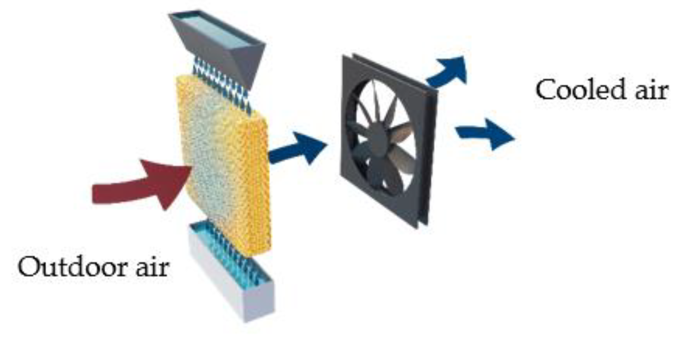
2.1. Analysis of the Evaporative Cooling System Efficiency in Real Conditions

Direct evaporative cooling is a method of cooling air by contact with water, which initiates the evaporation process. The efficiency of the direct evaporative cooling system was examined in practice on a real installation to study the effect on reducing energy consumption and improving indoor environmental quality. The system operation data was provided by Blue energy global Ltd. (Ogres novads, Latvia).

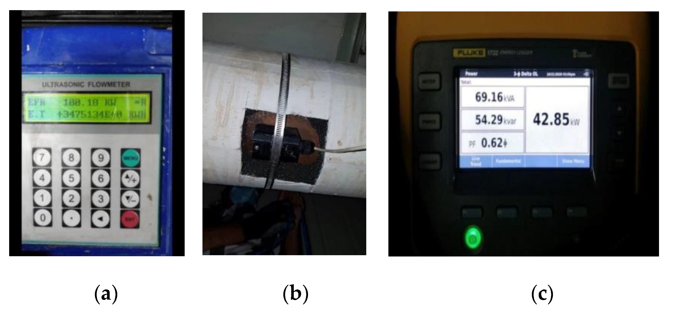
2.1.1. System Description

Type of structure: Office building in Dubai, Saudi Arabia.
Cooling equipment: chiller X with four piston-type compressors. Cooling capacity as per manufacturer’s data performance sheet: 555 kW.
Electricity consumption as per manufacturer’s data performance sheet: 194 kW.
Measuring instruments: an RIF600 ultrasonic water flow meter was used to measure chiller effectiveness and a Fluke energy monitoring equipment was used to measure electricity consumption (see Figure 1).
A significant improvement in chiller performance would be one of the effects of the direct evaporative cooling system over the chiller, and would be displayed in data sets of electricity input against cooling output. It was therefore suggested that “day on/day off” testing be undertaken to record:
  • Chiller electricity consumption;
  • Chiller cooling output;
  • Hourly external dry-bulb air temperature hourly external relative humidity.
The suggested duration of the testing mode was six weeks, with the aim of maximizing the potential of yielding the greatest number of readings on each condition.

2.1.2. Description of System Tests

Two regression models of electricity consumption were created–representing the “on” and “off” conditions, respectively–with chiller cooling output and cooling degree-day values as independent variables. Cooling degree days were derived from dry-bulb temperatures, with the relative humidity readings held in reserve in case it was deemed necessary to develop an enthalpy-based model. Effective savings inferred from the difference between the two regression models and annual expected savings were extrapolated from them.
During the test period, four “on” and “off” sequences were detected. Data on chiller electricity consumption and cooling output were collected at 30 min intervals and separated into three distinct sets. One set took place during intervals when adiabatic system was in operation and the other two sets in periods when it was disabled.

2.1.3. Testing Procedures

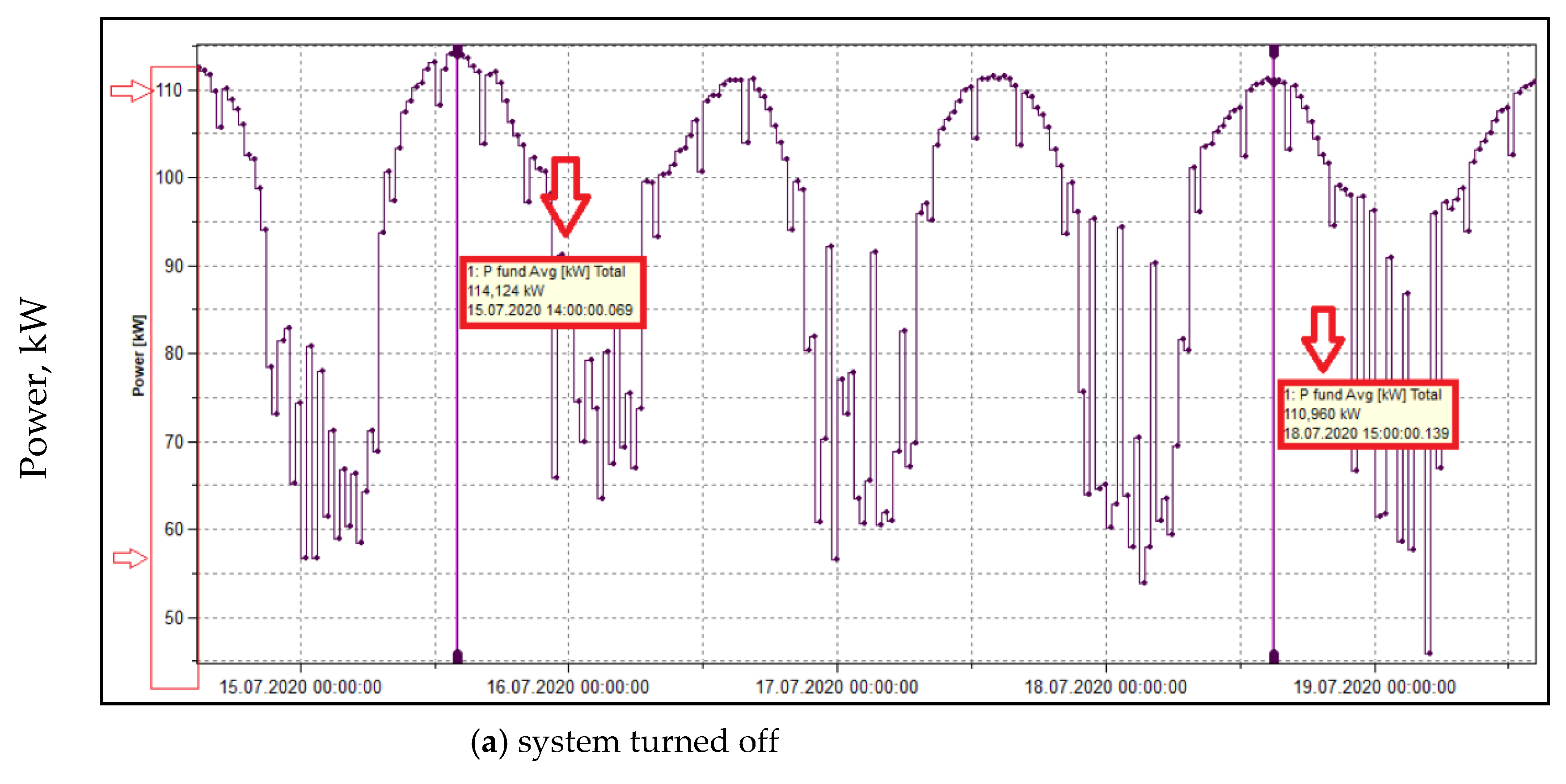
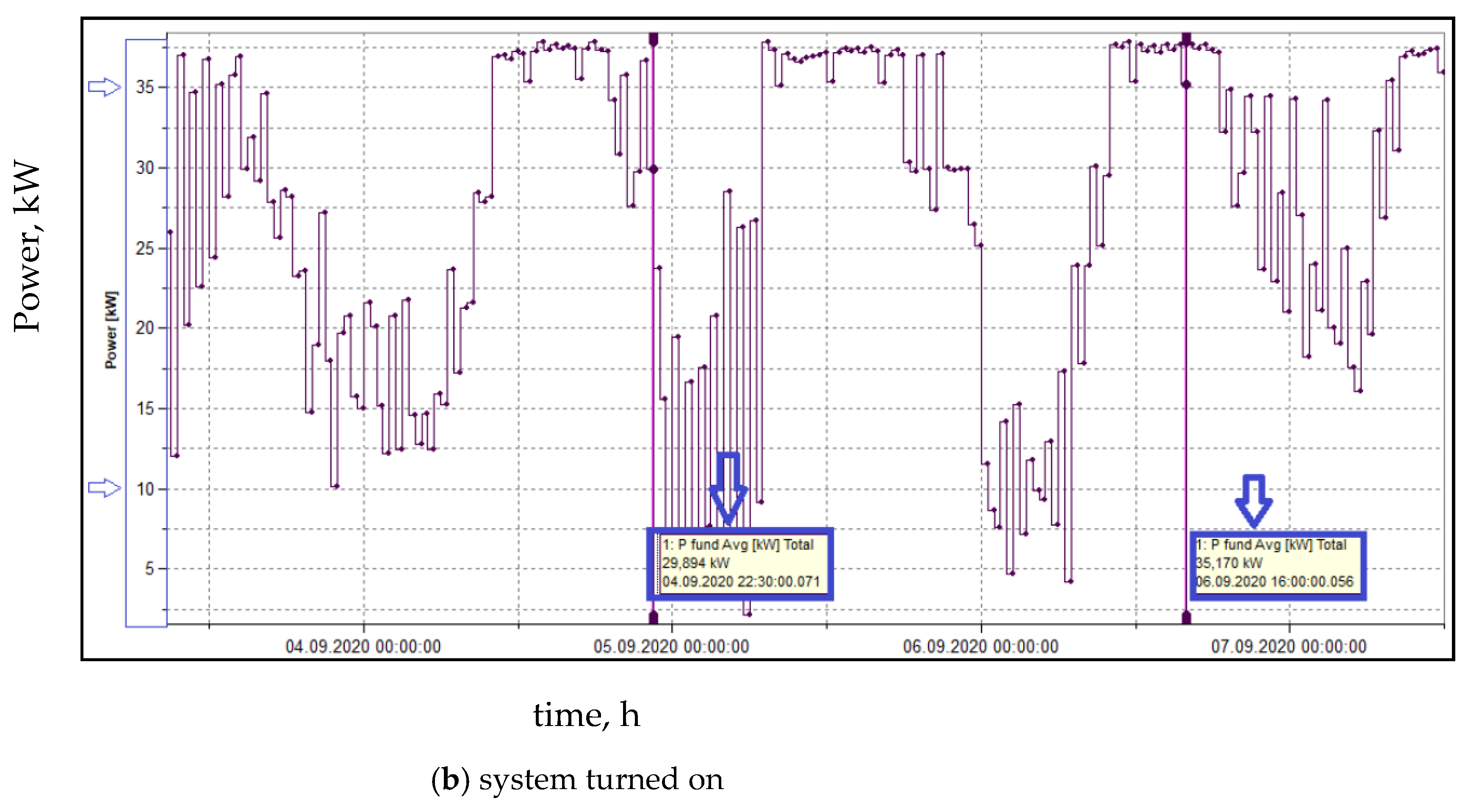
  • Test No. 1: Chiller electricity energy test 4 Days “Off”/4 Days “On”–direct evaporative cooling system comparison
4 Days “Off”/4 Days “On”–direct evaporative cooling system comparison. Reading data from the Fluke energy monitoring system, the average electricity consumption of the chiller with the direct evaporative cooling system turned off was 11,057 kWh and 7740 kWh with the direct evaporative cooling system on for four days. Average chiller electricity savings for four days were 3317 kWh. Water consumption during four days amounted to 11.04 m3. The Fluke energy monitoring system indicated electricity consumption of 90–114 kWh with the direct evaporative cooling system turned off (see Figure 2a) and 27–50 kWh with the direct evaporative cooling system turned on (see Figure 2b).
Figure 2 on X-axes shows seven days time interval.
  • Test No. 2: Chiller electricity energy test 7 Days “Off”/7 Days “On” and Test No. 3: Chiller electricity energy test 13 Days “Off”/13 Days “On”–direct evaporative cooling system comparison.
Tests 2 and 3 were carried out in accordance with Test 1, the results are summarized in Table 1.
  • Test No. 4: compressor COP test, test duration: 2 h
To assess the chiller’s compressor COP (Coefficient of Performance) a COP test was carried out. During the COP test the following equipment was used: an ultrasonic flowmeter, an RIL600W BTU (British thermal unit) meter and a Fluke energy meter. Inlet and return water flow were measured, as well as water temperature and energy consumption determined in real time against energy consumption. Compressor COP calculations were conducted on a single compressor, as it was the sole compressor in operation during the conduction of the test. Thus, this Chiller COP test does not indicate all chillers EER (energy efficiency ratio) when operating in changing conditions and under variable compressor loads. Compressor COP calculations were as follows: 100.18 kW/42.85 = 2.3. A comprehensive chiller EER or COP test would show a different picture if the COP test had been conducted for a longer period and under different chiller loads, ranging from 25% to 100%.
In all three cases energy savings consensually make 30%, 27% and 26%. This numbers are close to before mentioned studies made in similar climate.

2.2. Analysis of the Dependence of the System Efficiency on the Inlet Water Temperature

Direct evaporative cooling efficiency depends on three parameters: inlet water temperature, wet-bulb temperature and inlet water air-mass ratio. In our case, the main task was to investigate whether the temperature of the inlet water supplied to adiabatic precooling pad could change the heat balance and whether additional air cooling might be required. Thus, determining whether additional energy will be required to pre-cool the inlet water. Figure 3 shows the principle scheme of adiabatic cooling process. An ambient warm air enters through an adiabatic precooling pad that is evenly saturated with water. Water evaporates by absorbing heat from the air mass which reduces the temperature of the outlet air. The mathematical model of the evaporative cooling process with inlet water temperatures of 40 °C and 20 °C was developed.
Within this study, two cases A and B were examined.
Case A:
Air temperature Tair = 40 °C; RH = 30%; Inlet water temperature Tinwater = 40 °C
The air must be humidified up to 90%
Air volume Vair = 10,000 m3/h.
Case B:
Air temperature 40 °C; RH 30%; Inlet water temperature Tinwater = 20 °C
The air must be humidified up to 90%
Air volume Vair = 10,000 m3/h.
The concept of saturation efficiency is illustrated in the scheme of psychrometric chart with respect to the examined parameters, as shown in Figure 4. The dry-bulb temperature (TDB) reduces along a constant wet-bulb line [Point ① to Point ②] when using an adiabatic pre-cooling system. Points ① and ② represents air moisture and temperature parameters.

2.2.1. Case A

The following assumptions were introduced: Tair = 40 °C, RH = 30%; Tinwater = 40 °C.
The water balance at the adiabatic precooling pad.
Density of air [30]:
Air ρ 40 ° ( 30 % ) = 1.103 kg/m3.
Air mass flow rate is calculated by the following equation:
M a i r   = ρ 40 ° ( 30 % ) ·   V a i r   ,
M a i r   = 1.103 × 10000 = 11030   kg / h .
Water flow rate is calculated by the following equation:
G H 2 O = M a i r · Δ H R ,
G H 2 O = 11.030   ( 0.0172 0.014 ) = 35.3 kg h ,
where ΔHR—humidity ratio difference, in kg/kg.
The energy balance at the adiabatic precooling pad.
Inlet water enthalpy is calculated by the following equation:
h i n w a t e r = M a i r · h G H 2 O   ·   h e ,
where h —specific enthalpy, in kJ/kg.
h e evaporation ,   kJ / kg .
h i n w a t e r = 11.030 × 96 35.3 × 2400 = 974.160   kJ / kg ,
974160 11030 = 88.3   kJ / kg → corresponding to point ② (see Figure 2).
According to the developed model, if the amount of inlet water and air mass flow is determined and the inlet water temperature is known, the exhaust air temperature at the cooling cushion for 100% saturation could be evaluated, along with the saturation efficiency ( E % ). In our case, the air is saturated to 90%.
Manufacturers of adiabatic pads refer to the saturation efficiency as the ability of the pad to reach the dry bulb exiting temperature at a known inlet dry bulb temperature. The dry bulb temperature exiting the adiabatic pad media is calculated using the equation below.
T D B   e x i t i n g = T D B   e n t e r i n g   E ( % )   · ( T D B   e n t e r i n g   T W B   e n t e r i n g ) ,
Adiabatic pad saturation efficiency is calculated by modifying Equation (4) to solve for efficiency:
E = ( T D B   e n t e r i n g   T D B   e x i t i n g ) ( T D B   e n t e r i n g   T W B   e n t e r i n g ) × 100 % ,
where TWB—wet bulb temperature, °C.
Saturation efficiency according to the Formula (4):
E = ( 40   ° C 24.6   ° C ) ( 40   ° C 23   ° C ) × 100 % = 15.4   ° C 17   ° C × 100 % = 90 %.

2.2.2. Case B

The following assumptions: Tair = 40 °C; RH = 30%; Tinwater = 20 °C; air flow TDB = 40 °C;
h = 96 kJ/kg; water with T = 20 °C → water with T = 40 °C.
Air enthalpy is calculated by the following equation:
h a i r = M a i r   · h ,
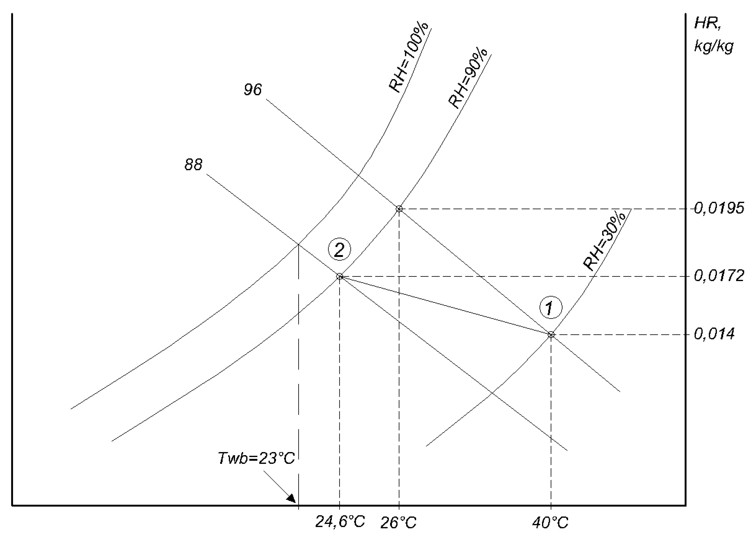
  • hair = 11.030 (kg/h) × 96 (kJ/kg) = 1058 MJ/h,
  • therefore water entalpy at 20 °C
  • h H 2 O 20   ° C = 83 KJ/kg and at 40 °C
  • h H 2 O 40   ° C = 167.5 KJ/kg.
Difference in air flow enthalpy at certain temperatures of inlet water is calculated by the equation below:
Δ h a i r = ( h H 2 O 40   ° C h H 2 O 20   ° C )   × G H 2 O ,
Δ h a i r = 84.5   ( kJ / kg )   ×   35.3   ( kg / h ) = 2.98   MJ / h .
Water heating from 20 °C to 40 °C requires 2.98 1058 = 0.3 % on the enthalpy of air flow.

3. Results

In regard to the evaporative cooling systems, the performance of evaporative cooling pads are dependent on a number of factors: surface area, pad thickness, the type of the pad material, perforation pattern and orifice size, water volume, water flow rate and relative humidity of air passing through the pad [31]. An effective material must feature properties such as efficient heat and mass transfer, low pressure drop, economic rationality, prevention of bacterial growth and the flexibility to be executed in various shapes and sizes. The investigated cooling system comprises a cellulose pad of 0.5 × 0.5 m2 in size and 100 mm in thickness.
After assessing the energy consumption of a particular chiller for a period of two months, test results of the X chiller with piston-type compressors show that with the direct evaporative cooling system turned off, the chiller load is over 45%. When put into operation, direct evaporative cooling system allows the cooling facilities to save from 25% up to 69% of chiller energy. According to the chiller data performance sheet-at an outside air temperature of 46 °C, the chiller COP is 2.1. Therefore, the real energy efficiency ratio (EER) of this X chiller at an outdoor temperature of 46 °C is, in fact, likely to be at around 1.5.
The X chiller with four piston-type compressors operates in an ON-OFF principle. This stipulates that when the cooling load and capacity of a compressor changes, the electricity consumption does not change significantly. The chiller’s four compressors operate with a load ranging from 75% to 100%.
After analyzing electricity data it can be derived that the average electricity consumption of one compressor is, on average, 50 kWh. In a case when the chiller load is around 45% and two compressors are running, electricity consumption is, on average, 100 kWh.
With direct evaporative cooling system in operation, which substantially reduces incoming air temperature into the condenser by 15 °C and ensures a significantly lower chiller condensing temperature (preventing the chiller from turning on a second compressor), a substantial decrease of 45–50% in electricity consumption was observed. The enthalpy diagram in Figure 5 shows the capacity of the compressor.
The picture on the right shows the limitation of compressor operation based on outdoor air temperature.
In some instances, such as when three compressors were running (compressors 1 and 2 at full load of 90–100% and compressor 2 at 10% load) and the chiller load is 60%, switching on the direct evaporative cooling system switches off two compressors and operates with a single compressor. The resulting reduction in electricity consumption can be observed in the readings by the Fluke energy meter.
According to the developed mathematical model and the calculations performed for Cases A and B, the saturation efficiency falls within the range of 65–97% at speed limit − 100 fpm = 30 m/60 − 0.5 m/s ÷ 1. Water flow rate is Δ G H 2 O   = 36 kg/h with dry bulb temperature T D B   = 24.6 °C (after wetting). Analyzing the heat balance of the system, water heating from 20 °C to 40 °C requires only about 0.3% of the airflow enthalpy. Therefore, reducing the water temperature from 40 °C to 20 °C will not change the heat balance; as a result, additional air cooling will not be provided. Hence, there is no need to additionally precool the water and, eventually, consume additional energy to increase the efficiency of the system.
Taking into account electricity savings and water consumption (direct evaporative cooling system status “ON”) for a real operating air conditioning system in Dubai, the ROI (return on investment) calculation is presented below (Table 2).
Cost breakdown used in the calculations are valid as of August 2021; the Latvian bank currency converter was used to convert the currency to euros. Assuming that the operation period of the tested compressor will be 60% of the air-conditioning duration with switching on direct evaporative cooling system, the total annual electricity savings for the system come out to 122,000 kWh/year (or about 12,686.29 EUR/year). The estimated cost of the direct evaporative cooling for air cooling is 85 EUR per kW [26]. The resulting ROI is approximately 4.2 years.

4. Discussion

This study focused on identifying the potential advantages of air cooling equipment with direct evaporative cooling technology over the cooling equipment without this technology. The results showed that with direct evaporative cooling system in operation an incoming air temperature into a condenser is considerably reduced, ensuring a significantly lower chiller condensing temperature and, as a result, a substantial decrease of 45–50% in electricity consumption.
The results provide the expediency of conducting further research in this area, in particular with regards to analyzing various materials for the adiabatic precooling pads.
Nevertheless, the limiting factor of using the direct evaporative cooling with adiabatic precooling pad technology is its limited application potential in extreme climate conditions such as dusty, arid areas. In this study, the impact of adiabatic precooling pads clogging on the system performance of the entire system was not considered. In hot-dry climate regions, dust particles tend to stick to the pads, which leads to their rapid deterioration. Therefore, this not only reduces the efficiency of the air conditioning system but also complicates its servicing, which in turn makes the system’s operation and maintenance more expensive. The next stage of this study will be a review of various materials for adiabatic precooling pads, as well as the feasibility of using the newly developed metal precooling pad. The proposed advantages of the metal pad are increased longevity and ease of cleaning it from dust particles.
The results of this study are in good agreement with the practical applications and the findings correlate with the performance data of installed systems, suggesting that the evaporative cooling system is feasible in the regions where hot and arid climate conditions prevail, such as the Middle East.

5. Conclusions

Air conditioning equipment with a direct evaporative cooling system can be used for providing comfortable indoor temperature in buildings, thus improving the EER by reducing the electricity consumption for system operation. The key findings of this study are as follows:
  • The electricity consumption of the X chiller equipped with the direct evaporative cooling system consumes, on average during a 1-day test, approximately 1935 kWh, which comes out to 472 MWh per year. Without direct evaporative cooling system, the average chiller electricity consumption during a 1-day test is around 2766 kWh which results in 675 MWh per year. Therefore, the average energy savings will be 203 MWh annually, if the operation period of the tested compressor is 100% of the air-conditioning duration with direct evaporative cooling system switched on. For the examined case the operation period was 60%, which results in average energy savings of around 122 MWh annually.
  • When the inlet water temperature was below the wet bulb temperature, an increase in the air to water mass ratio was observed. According to the calculations, it was concluded that the decrease of the inlet water temperature did not cause significant changes in the heat balance of the system.
  • The expected ROI period of such system is 4.2 years.

Author Contributions

Conceptualization, A.B. (Anatolijs Borodinecs) and K.L.; methodology, A.B. (Anatolijs Borodinecs); validation, A.P., A.B. (Arturs Brahmanis) and A.G.; formal analysis, D.Z. and A.Z.; investigation, A.B. (Anatolijs Borodinecs), K.L. and A.B. (Arturs Brahmanis); data curation, D.Z. and A.Z.; writing—original draft preparation, K.L., A.P.; writing—review and editing, A.B. (Anatolijs Borodinecs); visualization, A.P.; supervision, A.B. (Anatolijs Borodinecs); Conceptualization and climate relevance, N.V. All authors have read and agreed to the published version of the manuscript.

Funding

This research received no external funding.

Institutional Review Board Statement

Not applicable.

Data Availability Statement

Data available on request due to restrictions eg privacy or ethical.

Acknowledgments

This research is supported by ERDF project “Development of a new prototype of adiabatic cooling panels to ensure the sustainability and energy efficiency of cooling equipment”, Nr. 1.1.1.1/19/A/002.

Conflicts of Interest

The authors declare no conflict of interest.

Nomenclature

h e evaporation, kJ/kg
h i n w a t e r inlet water enthalpy, kJ/kg
G H 2 O water flow rate, kg/h
M a i r   air mass flow rate, kg/h
h specific enthalpy, kJ/kg
RHrelative humidity, %
Tairair temperature, °C
TDBdry bulb temperature, °C
Tinwaterinlet water temperature, °C
TWBwet bulb temperature, °C.
Vairair volume, m3/h
ρdensity of air, kg/m3

References

  1. Delmastro, C.; Abergel, T. Is Cooling the Future of Heating?—Analysis—IEA. Available online: https://www.iea.org/commentaries/is-cooling-the-future-of-heating (accessed on 11 September 2021).
  2. Cooling as a Service (CaaS). The Global Innovation Lab for Climate Finance. Available online: https://www.climatefinancelab.org/project/cooling-service/ (accessed on 11 September 2021).
  3. Martin, A. Chart: Air Conditioning Biggest Factor in Growing Electricity Demand Statista. Available online: https://www.statista.com/chart/14401/growing-demand-for-air-conditioning-and-energy/ (accessed on 11 September 2021).
  4. European Commission: Clean Energy for all Europeans. 2019. Available online: https://ec.europa.eu/info/news/clean-energy-all-europeans-package-completed-good-consumers-good-growth-and-jobs-and-good-planet-2019-may-22_en (accessed on 11 September 2021).
  5. Sousa, A.; Aguilar-Alba, M.; García-Barrón, L. Climate Change, Aquatic Ecosystems and Human Infectious Diseases in a Globalised World. Atmosphere 2021, 12, 653. [Google Scholar] [CrossRef]
  6. Kim, S.H.; Yoon, Y.R.; Kim, J.W.; Moon, H.J. Novel integrated and optimal control of indoor environmental devices for thermal comfort using double deep q-network. Atmosphere 2021, 12, 629. [Google Scholar] [CrossRef]
  7. Zajacs, A.; Borodiņecs, A.; Bogdanovičs, R. Assessment of the efficiency and reliability of the district heating systems within different development scenarios. In Smart Innovation, Systems and Technologies; Springer: Singapore, 2020. [Google Scholar] [CrossRef]
  8. Palomba, V.; Varvagiannis, E.; Karellas, S.; Frazzica, A. Hybrid Adsorption-Compression Systems for Air Conditioning in Efficient Buildings: Design through Validated Dynamic Models. Energies 2019, 12, 1161. [Google Scholar] [CrossRef] [Green Version]
  9. Hu, S.; Yan, D.; Qian, M. Using bottom-up model to analyze cooling energy consumption in China’s urban residential building. Energy Build. 2019, 202, 109352. [Google Scholar] [CrossRef]
  10. Ketwong, W.; Deethayat, T.; Kiatsiriroat, T. Performance enhancement of air conditioner in hot climate by condenser cooling with cool air generated by direct evaporative cooling. Case Stud. Therm. Eng. 2021, 26, 101127. [Google Scholar] [CrossRef]
  11. Yang, J.; Chan, K.T.; Wu, X.; Yu, F.W.; Yang, X. An analysis on the energy efficiency of air-cooled chillers with water mist system. Energy Build. 2012, 55, 273–284. [Google Scholar] [CrossRef]
  12. Huang, C.N.; Ye, Y.H. Development of a water-mist cooling system: A 12,500 Kcal/h air-cooled chiller. Energy Rep. 2015, 1, 123–128. [Google Scholar] [CrossRef] [Green Version]
  13. Yang, J.; Chan, K.T.; Wu, X.S. Experimental studies of energy performance of air-cooled chillers with water mist system. In Proceedings of the 2nd International Postgraduate Conference on Infrastructure and Environment, IPCIE 2010, Hong Kong, China, 1–2 June 2010. [Google Scholar]
  14. Yang, J.; Chan, K.T.; Wu, X. Application of water mist pre-cooling on the air-cooled chillers. Proceedings of IBPSA 2009-International Building Performance Simulation Association 2009, Glasgow, UK, 27–30 July 2009. [Google Scholar]
  15. Sarbu, I.; Adam, M. Experimental and numerical investigations of the energy efficiency of conventional air conditioning systems in cooling mode and comfort assurance in office buildings. Energy Build. 2014, 85, 45–58. [Google Scholar] [CrossRef]
  16. Andrade, C.; Mourato, S.; Ramos, J. Heating and Cooling Degree-Days Climate Change Projections for Portugal. Atmosphere 2021, 12, 715. [Google Scholar] [CrossRef]
  17. Gyilbag, A.; Amou, M.; Tulcan, R.X.S.; Zhang, L.; Demelash, T.; Xu, Y. Characteristics of Enhanced Heatwaves over Tanzania and Scenario Projection in the 21st Century. Atmosphere 2021, 12, 1026. [Google Scholar] [CrossRef]
  18. Yu, F.W.; Chan, K.T. Improved energy performance of air-cooled chiller system with mist pre-cooling Mist improvement on air-cooled chillers. Appl. Therm. Eng. 2011, 31, 537–544. [Google Scholar] [CrossRef]
  19. Abaranji, S.; Panchabikesan, K.; Ramalingam, V. Experimental study on the direct evaporative air-cooling system with vermicompost material as the water storage medium. Sustain. Cities Soc. 2021, 71, 102991. [Google Scholar] [CrossRef]
  20. Cui, Y.; Zhu, J.; Zoras, S.; Liu, L. Review of the recent advances in dew point evaporative cooling technology: 3E (energy, economic and environmental) assessments. Renew. Sustain. Energy Rev. 2021, 148, 111345. [Google Scholar] [CrossRef]
  21. Kumar, S.; Salins, S.S.; Reddy, S.V.K.; Nair, P.S. Comparative performance analysis of a static & dynamic evaporative cooling pads for varied climatic conditions. Energy 2021, 233, 121136. [Google Scholar] [CrossRef]
  22. Shahzad, K.; Sultan, M.; Bilal, M.; Ashraf, H.; Farooq, M.; Miyazaki, T.; Sajjad, U.; Ali, I.; Hussain, M.I. Experiments on energy-efficient evaporative cooling systems for poultry farm application in Multan (Pakistan). Sustainability 2021, 13, 2836. [Google Scholar] [CrossRef]
  23. Ashraf, H.; Sultan, M.; Shamshiri, R.R.; Abbas, F.; Farooq, M.; Sajjad, U.; Md-Tahir, H.; Mahmood, M.H.; Ahmad, F.; Taseer, Y.R.; et al. Dynamic evaluation of desiccant dehumidification evaporative cooling options for greenhouse air-conditioning application in multan (Pakistan). Energies 2021, 14, 1097. [Google Scholar] [CrossRef]
  24. Ndukaife, T.A.; Nnanna, A.G.A. Enhancement of Performance and Energy Efficiency of Air Conditioning System Using Evaporatively Cooled Condensers. Heat Transf. Eng. 2019, 40, 375–387. [Google Scholar] [CrossRef]
  25. ASHRAE. ANSI/ASHRAE Standard 55-2017: Thermal Environmental Conditions for Human Occupancy. 2017. Available online: https://webstore.ansi.org/Standards/ASHRAE/ANSIASHRAE552020?source=blog&_ga=2.28042556.1409240200.1631498293-1225420834.1631498293 (accessed on 11 September 2021).
  26. Sajjad, U.; Abbas, N.; Hamid, K.; Abbas, S.; Hussain, I.; Ammar, S.M.; Sultan, M.; Ali, H.M.; Hussain, M.; Rehman, T.; et al. A review of recent advances in indirect evaporative cooling technology. Int. Commun. Heat Mass Transf. 2021, 122, 105140. [Google Scholar] [CrossRef]
  27. Martínez, P.; Ruiz, J.; Martín, Í.; Lucas, M. Experimental study of an ultrasonic mist generator as an evaporative cooler. Appl. Therm. Eng. 2020, 181, 116057. [Google Scholar] [CrossRef]
  28. Shanks, K.; Nezamifar, E. Impacts of climate change on building cooling demands in the UAE. In Proceedings of the SB13 Dubai: Advancing the Green Agenda Technology, Practices and Policies, Dubai, United Arab Emirates, 8–10 December 2013; Volume 80. [Google Scholar]
  29. Mirkovic, M.; Alawadi, K. The effect of urban density on energy consumption and solar gains: The study of Abu Dhabi’s neighborhood. Energy Procedia 2017, 143, 277–282. [Google Scholar] [CrossRef]
  30. Shelquist, R. Shelquist Engineering. Equations—Air Density and Density Altitude. Available online: https://wahiduddin.net/calc/density_altitude.htm (accessed on 11 September 2021).
  31. Malli, A.; Seyf, H.R.; Layeghi, M.; Sharifian, S.; Behravesh, H. Investigating the performance of cellulosic evaporative cooling pads. Energy Convers. Manag. 2011, 52, 2598–2603. [Google Scholar] [CrossRef]
Figure 1. Measuring instruments. (a) BTU meter processor, (b) BTU meter clam, (c) Fluke energy meter.
Atmosphere 12 01205 g001
Figure 2. Fluke energy meter readings with direct evaporative cooling system turned off/turned on.
Atmosphere 12 01205 g002aAtmosphere 12 01205 g002b
Figure 3. Principle scheme of adiabatic cooling.
Atmosphere 12 01205 g003
Figure 4. Schemes of psychrometric chart for cases parameters.
Atmosphere 12 01205 g004
Figure 5. Enthalpy diagram. (a) Enthalpy of theoretical cycle (b) Compressor theoretical working curve.
Atmosphere 12 01205 g005
Table 1. Results of the Tests.
TestThe Direct Evaporative Cooling System StatusElectricity Consumption (kWh)Water Consumption (m3)
No. 1:4 daysOff
On
11,057
7740

11.04
No. 2:7 daysOff
On
16,536
12,071

20.04
No. 3:13 daysOff
On
27,593
20,295

36.40
Table 2. ROI calculation.
Direct Evaporative System StatusAverage Consumption per Year 1Price, EURPrice, EURSavings
Electricity, kWhWater, mElectricity 2Water 2Electricity, kWhEUR
OFF675,000 70,878.30 70,878.30
ON472,00067349,516.681769.8051,286.4820,300021,209.90
1—system operation about 8 months per year (operation period of the tested compressor 100% of the air-conditioning duration with switching on direct evaporative cooling system); 2—electricity and water prices calculated according to Dubai Electricity and Water Authority provided Tariff Calculator (https://www.dewa.gov.ae/en/consumer/billing/slab-tariff, accessed on 11 September 2021).
Publisher’s Note: MDPI stays neutral with regard to jurisdictional claims in published maps and institutional affiliations.

