Single-Ended Fast Protection for Transient Power of Multi-Terminal Flexible and Direct Power Grids Containing Renewable Energy
 Jieshan Shan
  Hongchun Shu
- Faculty of Electric Power Engineering, Kunming University of Science and Technology, Kunming, China
With the proposal of the carbon peak goal, a multi-terminal flexible DC grid containing various renewable energy becomes the one of main ways of renewable energy power transmission. Thus, it is increasingly important to improve its transmission reliability and stability. This paper proposes a single-ended protection principle based on the analysis method of transient power change for the “mesh structure” ring-shaped flexible direct current (DC) grid. Based on the propagation characteristics of voltage, current, and anti-traveling waves during fault periods, the transient power variation coefficient based on SOD transformation is introduced to distinguish the internal and external faults. Besides, simulation based on the PSCAD/EMTDC platform within the Zhangbei four-port network verifies the effectiveness of the proposed protection principle under various fault conditions. Meanwhile, the protection criterion is designed according to the difference in the change coefficient of the transient power SOD within and outside the fault time zone. Moreover, the setting value of the start of protection is obtained by analyzing the simulation results, thus a set of fast and reliable single-ended protections for the same-side short-time transient power window of an enhanced flexible straight power grid is developed via combining it with the starting criterion of a sudden voltage change.
1 Introduction
With China’s 2060 carbon neutralization target (Tang et al., 2013), the proportion of renewable energy in the energy system will inevitably increase year by year (Li et al., 2016a), and DC load will also continue to rise with the promotion of DC transmission technology (Li et al., 2015). The multi-terminal flexible DC grid containing renewable energy will likely become the main way of renewable energy power transmission (Sun et al., 2020; Bakeer et al., 2021), and improving its transmission reliability is a worthwhile research topic (Liu et al., 2020; Nayak et al., 2021).
In order to improve the protection performance of multi-terminal flexible direct current (DC) grid lines, much related research work has been carried out. Some literature (Li et al., 2016b) has employed the blocking effect of high-frequency components on line boundary elements (Tian et al., 2019; Bakeer et al., 2021) to distinguish the high-frequency transient energy on both sides of the boundary during faults. Though different judgment of internal and external faults effectively reduces the burden of protection setting, an appropriate simulation setting is still required. A wavelet transformation method was devised in reference (ASV et al., 2020) to extract the transient characteristics of the faults inside and outside the area according to the boundary characteristics of the DC line to construct the best judgment for its protection (Zhao et al., 2011). Further literature (Liu et al., 2017) has been directed at the structure design of two-level VSC converters in the DC system. Based on the boundary element energy storage capacitor and DC reactor, a protection criterion based on the transient voltage ratio method has been proposed. More studies (Tong et al., 2019) measured the attenuation characteristics difference of the same-name traveling wave and the different-name traveling wave on both sides of the fault line and the non-fault line. Meanwhile, the Hausdorff distance was also adopted to form a set of wave-matched longitudinal differential protections (Tong et al., 2019; Wang et al., 2020).
Based on the aforementioned prior studies, this paper proposes a new principle of single-ended protection based on the transient power change analysis method for the “mesh structure” ring-shaped flexible DC grid. Based on the propagation characteristics of the forward wave and anti-traveling wave of voltage and current during a fault period, the transient power variation coefficient based on SOD transformation is introduced to distinguish the internal and external faults. In particular, simulation on PSCAD/EMTDC platform effectively verifies the protection principle under various fault conditions, and the start value of protection is set according to simulation results. Besides, a specific protection criterion is designed based on the difference of transient power SOD variation coefficient within and outside the fault time zone. Thus, a set of fast and reliable single-ended protection is devised through the combination of starting criterion of voltage sudden change.
2 Analysis of Fault Characteristics of Multi-Terminal Flexible DC Line
The structure of a typical multi-terminal flexible DC system is shown in Figure 1, in which f1 is an internal fault of the line, and f2, f3, f4, f5, and f6 are external faults of the line.
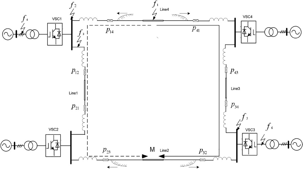
FIGURE 1. Schematic diagram of structural line failure of four-terminal flexible DC system.
There are two problems when considering a protection scheme intended mainly for line pilot protection under the failures of a multi-terminal flexible DC system. Firstly, when a near-end fault occurs, the electrical changes of the fault will be transmitted to the local protection at almost the same time as the fault occurs, and the opposite protection can only transmit acceleration signals to the local protection after the fault traveling wave arrives. The acceleration signal is the post-fault signal in relay protection that unconditionally trips the circuit breaker, but the delay of signal communication can cause damage to the transmission system. Thus, during protection scheme design, it is necessary to consider which fault condition produces the longest delay and set the upper limit of the time constraint according to the length of the line to prevent the converter from blocking before the protection action has occurred. Secondly, in the case of a near-end failure, the opposite side will produce reflected waves after traveling waves are transmitted. According to Peterson’s law, it is necessary to strictly ensure that the local side cannot be affected by the reflected waves of the opposite side before the fault processing is completed. The lower limit of time must be set according to the line length. The lower limit of time is the time it takes for a faulted traveling wave to propagate over a distance of twice the length of the line, and only an action time of less than this will ensure that the initial wavehead of the faulted traveling wave is not affected by the reflected wave. For practical engineering applications, if the length of each line of a multi-terminal network varies greatly, the difference of action effect of each line will be very obvious, which also brings certain difficulties to the setting of protection time.
As shown in Figure 1, when a fault occurs in f1, the fault traveling wave propagates along the line and converges at the M-point of the four-terminal network system due to the ring characteristics of the multi-terminal flexible DC transmission network. Because the directional characteristics of the traveling wave propagating at the mirror fault point are identical to the initial fault point, but the amplitude is reduced, there is an attenuation effect when propagating on the line. The characteristics of fault on protection p34 and p43 are similar to those on the M-point, only the magnitude is different. As the traveling wave propagates along the closed four-ended network, the faulty traveling wave from the fault must meet again at another point in the closed four-ended network, this point is the mirror fault point. The appearance of such a “mirror fault point” also brings difficulties to fault identification.
3 Line Protection Based on Transient Power Changes
3.1 Analysis of Electrical Characteristics
As shown in Figure 2, after a short-circuit fault occurs on the DC line, the voltage traveling wave is generated at the short-circuit point and propagates to both sides of the line. f1 is the internal fault of the line and f2 is the external fault of the line.
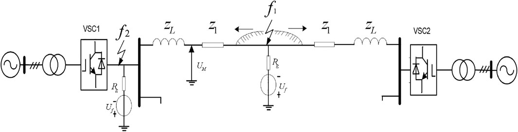
FIGURE 2. Schematic diagram of line fault voltage traveling wave propagation.
Let us define the transient power change as the product of the voltage fault component
When a fault occurs in the f1 area without considering the line attenuation, the fault component of the measured voltage can be expressed by
where
When an external f2 fault occurs, the fault component
where
When an external fault occurs, due to the existence of attenuation factor in the formula, the voltage component decays with time, that is, the voltage wave head of the fault point becomes gentle under the action of the current limiting reactor. When an internal fault occurs, the fault voltage component changes step by step because there is no attenuation factor in the formula. In the calculation formula of fault voltage component, it can be seen that the sensitivity of response to transition resistance can be improved most obviously through the fault voltage component.
As shown in Figure 3, after a short-circuit fault occurs on the DC line, f1 represents an internal fault of the line, and f2 denotes an external fault of the line.
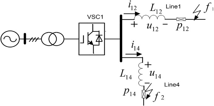
FIGURE 3. Schematic diagram of fault current propagation in adjacent lines.
The voltage of the smoothing reactor is proportional to the rate of change of current. The current-limiting reactor voltage
It is noteworthy that the polarity of the fault current is related to the location of the fault. As shown in Figure 3, it is assumed that the current reference direction is the positive direction of the bus flow to the line. Taking line protection p12 as an example, when the line fault f1 occurs in the positive direction, its polarity is positive and the value of inductance voltage
3.2 Analysis of Characteristics of Transient Power Variation
It can be seen from the above analysis that if we define the amount of transient power change as
4 SOD-Based Fault Identification Method
4.1 SOD Transformation Algorithm
In order to further increase the difference between internal faults and external faults, and improve the discrimination, this work makes certain changes on the basis of traveling wave analysis. SOD is the cross overlap difference transform. Besides, a fault identification algorithm based on cross-overlap differential transformation is also employed. The higher the order, the more sufficiently it can reflect the characteristics of high-frequency transients and the direction of their sudden changes, which can be expressed as
Based on this transformation, the difference between each sampling point can be enlarged. Moreover, the positive and negative transformation coefficients of each sampling point can also be alternated, which can be regarded as a difference calculation for every two sampling points and then an integral operation, so as to make the fault abrupt change more explicit. According to the subsequent simulation requirements, this work utilizes the seventh-order SOD algorithm for the simulated instantaneous power value.
4.2 Recognition of Internal and External Faults
As was analyzed in Section 3, during an internal line fault, multiple reflections of voltage and current traveling waves and multiple sudden changes in the direction of the transient power occur. Meanwhile, due to the influence of the current limiting reactor and the length of the line, the changes of the electrical quantities tend to be gentler when an external fault occurs, resulting in the direction change of the transient power change being greatly reduced. When
Taking the Zhangbei four-terminal flexible DC network as the simulation object, as shown in Figure 4, the converter stations in the figure are Zhangbei (vsc1), Beijing (vsc2), Fengning (vsc3), and Kangbao (vsc4), respectively.
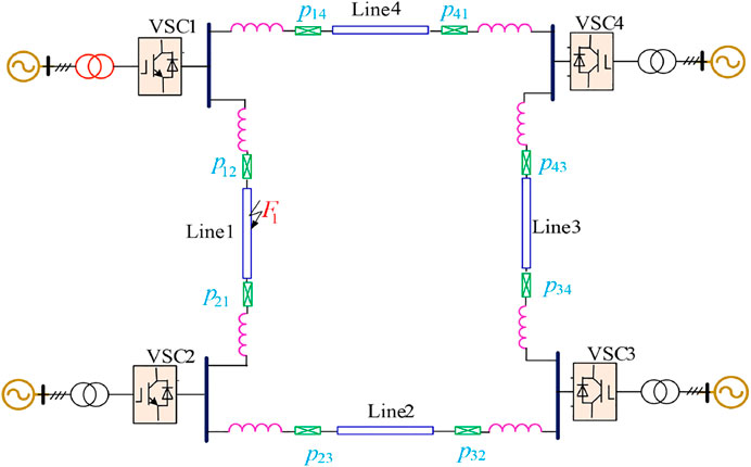
FIGURE 4. Schematic diagram of line failures of four-terminal flexible DC system.
Since the line mode component of each electrical quantity is less affected by frequency, and it is suitable for grounding and non-grounding faults, the line mode component is used in the following calculation. Assuming that the line mode components of fault voltage and current measured by P12 with 20 K sampling frequency are represented by u12 and i12, the higher the differential order is the more obvious the waveform amplitude changes.
The instantaneous power adopts a 7-order SOD transformation to meet the requirements, and the transformed value is expressed by
When a positive fault occurs on line 1 at a length of 100 km and the grounding resistance is 300 Ω, its voltage, current waveform, and transient power SOD transformation are shown in Figure 5.
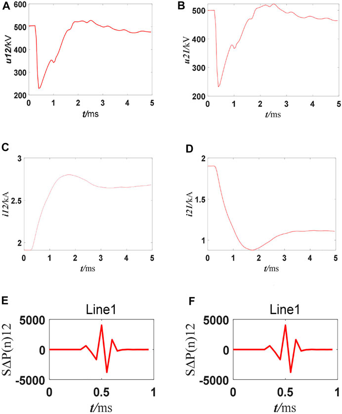
FIGURE 5. Voltage, current, and SΔP(n) waveform SOD transformation for line1 positive pole fault. (A) First-end positive fault voltage waveform; (B) Terminal positive fault voltage waveform; (C) First-end positive fault current waveform; (D) Terminal positive fault current waveform; (E) Line 1 head end SΔP(n) K = 4,037; (F) End of line 1SΔP(n) K = 4,063.
The transient power SOD transformation of non-faulty lines 2, 3, and 4 is shown in Figure 6.
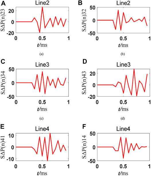
FIGURE 6. SΔP(n)K value of non-faulty line. (A) Line 2 head end SΔP(n) K = 26.5; (B) End of line 2 SΔP(n) K = 38.6; (C) Line 3 head end SΔP(n) K = 40.2; (D) End of line 3 SΔP(n) K = 27.5; (E) Line 4 head end SΔP(n) K = 11.8; (F) End of line 4 SΔP(n) K = 40.5.
In particular, the simulation results of each line are shown in Table 1.

TABLE 1. Line 1 combined power SOD conversion coefficient.
It can be seen from Table 1 that the transient power conversion coefficients of non-faulty lines show an obvious difference compared with that of faulty lines when various faults occur in different positions on the line and under different transition resistances. Based on this, the protection threshold can be set as the basis of distinguishing internal and external faults.
5 Conclusion
Fast and reliable DC fault identification is one of the key technologies for a multi-terminal ring flexible DC power grid. Based on the boundary characteristics of multi-terminal flexible DC power grids, a new fast protection method for a single terminal ring flexible DC power grid is proposed in this paper. Firstly, based on the refraction and reflection of the line boundary to the voltage and current traveling waves, the direction change is extracted through the SOD transformation coefficient of the instantaneous power, so as to realize fast and reliable fault identification. Secondly, the reliability of the protection is effectively improved via the over resistance characteristics of the fault voltage component and directional characteristics of the current component, and the difficulty of setting protections is reduced due to the high level of discrimination. It mainly contains the three following advantages, 1) fast operation speed that can respond within 6 ms after a fault occurs, which can effectively prevent the locking of a flexible DC power grid that can greatly improve the reliability of power supply; 2) fault identification is based on local information without communication; and 3) a strong ability to overcome transient resistance.
Data Availability Statement
The original contributions presented in the study are included in the article/Supplementary Material, further inquiries can be directed to the corresponding author.
Author Contributions
JS: Conceptualization, Writing—Reviewing and Editing. XT: Writing—Original draft preparation, Investigation. YD: Writing—Reviewing and Editing. HS: Supervision. YC: Supervision. JS: Conceptualization, Resources.
Conflict of Interest
The authors declare that the research was conducted in the absence of any commercial or financial relationships that could be construed as a potential conflict of interest.
Publisher’s Note
All claims expressed in this article are solely those of the authors and do not necessarily represent those of their affiliated organizations, or those of the publisher, the editors and the reviewers. Any product that may be evaluated in this article, or claim that may be made by its manufacturer, is not guaranteed or endorsed by the publisher.
Acknowledgments
The authors appreciatively acknowledge the support by Key Program of the National Natural Science Foundation of China (52037003); Major Special Project of Yunnan Province of China (202002AF080001).
References
Asv, V. L., Manyala, R. R., and Mangipudi, S. K. (2020). Design of a Robust PID-PSS for an Uncertain Power System with Simplified Stability Conditions. Prot. Control. Mod. Power Syst. 5 (1), 1–16. doi:10.1186/s41601-020-00165-9
Bakeer, A., Salama, H. S., and Vokony, I. (2021). Integration of PV System with SMES Based on Model Predictive Control for Utility Grid Reliability Improvement. Prot. Control. Mod. Power Syst. 6 (1), 1–13. doi:10.1186/s41601-021-00191-1
Li, B., He, J. W., Li, Y., and Ou, Y. (2016). Single-ended protection Scheme Based on Boundary Characteristic for the Multi-Terminal VSC-Based DC Distribution System. Proc. CSEE. 36 (21), 5741–5749. doi:10.13336/j.1003-6520.hve.20160926001
Li, X. Y., Zeng, Q., Wang, Y. H., and Zhang, Y. M. (2016). Control Strategies of Voltage Source Converter Based Direct Current Transmission System. High Voltage Eng. 42 (10), 3025–3037. doi:10.13648/j.cnki.issn1674-0629.2015.01.002
Li, Y., Luo, Y., Xu, S. H., Zhou, Y. B., and Yuan, Z. C. (2015). VSC-HVDC Transmission Technology: Application, Advancement and Expectation. South. Power Syst. Tech. 9 (1), 7–13.
Liu, J., Tai, N., and Fan, C. (2017). Transient-Voltage-Based Protection Scheme for DC Line Faults in the Multiterminal VSC-HVDC System. IEEE Trans. Power Deliv. 32 (3), 1483–1494. doi:10.1109/tpwrd.2016.2608986
Liu, J., Yao, W., Wen, J., Fang, J., Jiang, L., He, H., et al. (2020). Impact of Power Grid Strength and PLL Parameters on Stability of Grid-Connected DFIG Wind Farm. IEEE Trans. Sustain. Energ. 11 (1), 545–557. doi:10.1109/tste.2019.2897596
Nayak, P. C., Prusty, R. C., and Panda, S. (2021). Grasshopper Optimization Algorithm Optimized Multistage Controller for Automatic Generation Control of a Power System with FACTS Devices. Prot. Control. Mod. Power Syst. 6 (1), 1–15. doi:10.1186/s41601-021-00187-x
Sun, K., Yao, W., Fang, J., Ai, X., Wen, J., and Cheng, S. (2020). Impedance Modeling and Stability Analysis of Grid-Connected DFIG-Based Wind Farm with a VSC-HVDC. IEEE J. Emerg. Sel. Top. Power Electron. 8 (2), 1375–1390. doi:10.1109/jestpe.2019.2901747
Tang, G. F., He, Z. Y., and Pang, H. (2013). Research, Application and Development of VSC-HVDC Engineering Technology. Automation Electric Power Syst. 37 (15), 3–14.
Tian, P. T., Chen, Y., Wu, Q. F., Dai, G., Li, C. X., Lei, Y., et al. (2019). Study on Transient-Based protection Scheme and Cooperation Strategy Based on Flexible DC Grid. Power Syst. Prot. Control. 47 (14), 1–8. doi:10.19783/j.cnki.pspc.181046
Tong, N., Fan, L. X., and Lin, X. N. (2019). Waveform Matching Based protection Strategy for VSC-MTDC Independent on Synchronization and Boundary Component. Proc. CSEE. 39 (13), 3820–3833. doi:10.13334/j.0258-8013.pcsee.181082
Wang, Q., Yao, W., Fang, J., Ai, X., Wen, J., Yang, X., et al. (2020). Dynamic Modeling and Small Signal Stability Analysis of Distributed Photovoltaic Grid-Connected System with Large Scale of Panel Level DC Optimizers. Appl. Energ. 259, 114132. doi:10.1016/j.apenergy.2019.114132
Keywords: renewable energy power grid, flexible direct current, SOD conversion, transient power, single-ended protection
Citation: Shan J, Tian X, Dai Y, Shu H, Chang Y and Song J (2021) Single-Ended Fast Protection for Transient Power of Multi-Terminal Flexible and Direct Power Grids Containing Renewable Energy. Front. Energy Res. 9:747063. doi: 10.3389/fenrg.2021.747063
Received: 25 July 2021; Accepted: 09 August 2021;
Published: 13 September 2021.
Edited by:
Xiaoshun Zhang, Shantou University, ChinaReviewed by:
Guanhua Lu, South China University of Technology, ChinaXuehan Zhang, Korea University, South Korea
Copyright © 2021 Shan, Tian, Dai, Shu, Chang and Song. This is an open-access article distributed under the terms of the Creative Commons Attribution License (CC BY). The use, distribution or reproduction in other forums is permitted, provided the original author(s) and the copyright owner(s) are credited and that the original publication in this journal is cited, in accordance with accepted academic practice. No use, distribution or reproduction is permitted which does not comply with these terms.
*Correspondence: Hongchun Shu, kust_727@163.com