
FPGA Remote Laboratory Using IoT Approaches


Department of Electrical and Computer Engineering, University of Houston, Houston, TX 77204, USA
*
Author to whom correspondence should be addressed.
Electronics 2021, 10(18), 2229; https://doi.org/10.3390/electronics10182229
Submission received: 20 August 2021
/
Revised: 6 September 2021
/
Accepted: 9 September 2021
/
Published: 11 September 2021
(This article belongs to the Section Computer Science & Engineering)
Abstract
:Field-Programmable Gate Arrays (FPGAs) are relatively high-end devices that are not easily shared between multiple users. In this work, we achieved a remotely accessible FPGA framework using accessible Internet of Things (IoT) approaches. We sought to develop a method for students to receive the same level of educational quality in a remote environment that they would receive in a typical, in-person course structure for a university-level digital design course. Keeping cost in mind, we are able to combine the functionality of an entry-level FPGA and a Raspberry Pi Zero to provide IoT access for laboratory work. Previous works in this field allow only one user to access an FPGA at a time, which requires students to schedule time slots. Our design is unique in that it gives multiple users the ability to interact simultaneously with one individual top-level design on an FPGA. This novel design has the benefit for classroom presentations, collaboration and debugging, and eliminates the need for restricting student access to a time slot for FPGA access. Further, our hardware wrapper is lightweight, utilizing less than 1% of tested FPGA chips, allowing it to be integrated with resource-heavy designs. The application is meant to scale with large designs; there is no difference between how many users can interact with the remote design, regardless of the complexity of the design. Further, the number of users who can interact with a single project is limited only by the bandwidth restrictions imposed by Google Fire Base, which is far beyond any practical number of users for simultaneous access.
1. Introduction
With the presence of the Covid-19 Virus, declared a pandemic by the World Health Organization on 11 March 2020, the professional and educational world saw a sudden shift to an online presence. Sixty percent of higher education institutes have denoted that the current outbreak has increased their presence of online learning [1]. This shift called for the immediate development of tools that could better sustain online working environments than those that were already present. The removal of the classroom in a teaching environment also reduces the amount of interaction between teaching assistants, classroom peers, and professors. While this improves safety by reducing the transmission of Covid, this has a significant impact on the quality of learning [1]. Specific to courses that require expensive laboratory equipment, remote learning disenfranchises students from access to high end equipment, such as Field-Programmable Gate Arrays (FPGAs). These two key factors are especially prominent in the realm of digital design, as student interaction with teaching assistants on FPGA devices is pivotal when debugging hardware designs.
Our work seeks to increase the viability of a remote classroom specific for higher education in a digital-design curriculum. Specifically, this proposed method seeks to replicate the availability for direct teaching–assistant interactions with students on FPGA development boards in a collaborative, remote environment. Further, we seek to accomplish this using tools that would be affordable to an average student. By providing a tool that is both affordable and accessible to students, our proposed method will mitigate the negative effects of remote learning.
We focused our development efforts in integrating a variety of systems to provide a multi-platform, multi-user interactivity tool referred to as the Remote FPGA. The Remote FPGA platform implements the necessary hardware modules to allow for remote access for a single, top-level design at a time. We began our work by developing a method in which a design can be accessed via the Internet of Things (IoT) approach. This was accomplished by integrating an FPGA with a Raspberry Pi Zero. The user utilizes a tool, developed in Python, to embed the top module design into a set of hardware modules that allows the FPGA to communicate with the Raspberry Pi via a universal asynchronous receiver transmitter (UART). This tool has an easy to follow graphical user interface (GUI) that will output an FPGA project that can be readily uploaded to the FPGA/Raspberry Pi system.
Once the user has incorporated the remote FPGA hardware wrapper into their design, it can be accessed via a cross-platform application that has the potential to be deployed on both Android and iOS. The application emulates the development board used by the student and provides both input and output functionality. This increases remote lab mobility and accessibility; users no longer need access to a desktop computer or the physical development board to interact with their remote laboratory. The physical inputs on the development board are disabled to prevent interference with the remote access application. The lab also adds the ability to add various peripheral devices that are not already on the development board, such as seven segment displays, a variety of light emitting diodes (LEDs), push buttons, and slide switches.
Further, multiple users can access the same FPGA via the application at the same time. User inputs and outputs are reflected on all applications that are connected to the FPGA in real-time. This allows for multiple users to collaborate simultaneously on the same project, and is useful in laboratory grading and debugging. The ability to collaborate and have a number of users working on the same FPGA is unique to our work; other developments in online FPGA platforms allow only one user to connect to any given FPGA at a time [2,3,4,5,6,7]. Only allowing one user to access an FPGA remotely at a time is an issue, and leads to further difficulties: students must schedule a time slot to work on a remote FPGA which in turn limits the amount of time that students can have FPGA access, and students do not have the ability to collaborate on projects with costudents or teaching assistants. Our work remediates these issues by removing the limit on the number of users that can access a single FPGA.
Our proposed method was successfully implemented in a digital design course at the University of Houston. We tested our design methodology in the Spring of 2021, where students could access a completed lab with means to clarify instructions for expected inputs and outputs. Future plans include having students purchase their own development kit so as to allow for the upload of their ownlabs. Our work was launched on multiple development boards from Intel in conjunction with a Raspberry Pi Zero, bringing the total of this technology to approximately $110 per user.
The following sections of this paper are organized as follows. Section 2 describes the related research in the field. Section 3 discusses how we implemented our proposed method. Section 4 discusses the outcome of this work. Finally, Section 4.4 describes the value and future works of our proposed method.
2. Related Research
The following subsections cover a background of FPGAs along with other works that form the foundation of the Remote FPGA hardware platform. As made evident in subsequent sections, our work offers significant improvements over similar endeavors by adding multi-user collaboration and a cross-platform user interface (UI).
2.1. Field-Programmable Gate Arrays
FPGAs fall into the semiconductor category between microprocessors and Application-Specific Integrated Circuits (ASICs). FPGAs balance the programability of a microprocessor with the parallel processing power and speed of an ASIC [8]. FPGAs rely on a hardware description language (HDL), such as Verilog or Very High Speed Integrated Circuit Language (VHDL), to describe a set of complex logic functions [8,9].
FPGAs integrate some powerful features from both a conventional ASIC and a microprocessor [8,9]. Similar to an ASIC, the FPGA design is able to often rely on a clock operating in the mega- to gigahertz. This means that basic digital instructions can be processed anywhere from a few nanoseconds to picoseconds [10]. Similar to a microprocessor, on the other hand, FPGAs can be reprogrammed, whereas an ASICs cannot. The ability to reprogram an FPGA allows engineers to expand and modify digital designs without being required to reconstruct a digital circuit manually [8]. FPGAs constitute a wide range of modern applications, from digital signal processing [10,11] to machine learning [11,12], and from image processing [12] to data mining [13], and other functions not mentioned here.
2.2. FPGA IoT Integration Methods and Applications
While integrating FPGAs onto the IoT is far from a trivial task, FPGAs have a variety of uses and implementations as an IoT device [14,15,16,17,18,19]. IoT ready FPGAs are currently being utilized for online methods digital image processing, smart grid energy management, managing complex timing systems, broadcasting video recording solutions, data encryption, medical diagnoses and monitoring, and storage system solutions [14]. These topics open discussion not only for IoT FPGA applications, but also for the various methods of interfacing an FPGA with the Internet.
A popular method for providing an IoT interface with an FPGA is the Raspberry Pi [14,20]. A wireless monitoring system, proposed by Gophane et al., utilizes a combination of sensors alongside a Spartan 6 FPGA working in series with a Raspberry Pi 3 [20]. Gophane et al. further utilizes the functionality of the IoT by integrating their FPGA system with an Internet storage cloud for allowing access to the data acquired by the FPGA. While the Gophane et al. did not utilize the onboard WiFi of the Raspberry Pi 3, they were able to implement a ZigBee module to provide the IoT connectivity for the Raspberry Pi [20].
One further FPGA IoT integration method utilizes system-on-chip (SoC) FPGAs [21]. SoC FPGAs are available from multiple manufacturers such as Xilinx and Intel. These models of FPGAs include on-board processors, such as ARM Cortex-M3s or ARM Cortex-A9s [21]. Further, FPGA devices that do not have an on-board central processing unit (CPU) can utilize soft core processors, which essentially convert the FPGA into a SoC model [21]. By utilizing a SoC FPGA, Basilino et al. successfully implemented an IoT messaging processing system in which they increased message processing performance by 308% [21].
Once an FPGA has been integrated with the IoT, there is a seemingly endless amount of applications. With the combined power of parallel processing provided by the FPGA along with Internet access, researchers are able to tackle an incredible amount of issues in the modern era. For example, Kang et al. [15] utilize an IoT-capable FPGA for transmitting and mining data from an external server. The FPGA gives the ability to process the data extracted from the server with an improved collection rate of over 200% and an increase in energy efficiency of 15% [15].
One further application of an FPGA in the realm of IoT is edge computing, which was researched by Ferdian et al. [16]. By relying on an FPGA with IoT access, rather than a conventional microprocessor, Ferdian et al. utilized an FPGA as an IoT node to process and encrypt data before transmitting it. The edge computing provided by the FPGA is able to reduce the needed data bandwidth by 66% by encrypting and compressing the data as compared to raw, unprocessed data [16]. Further, as the FPGA can process data in parallel, Ferdian proved that the processing speed of the FPGA remained constant even when presented with an increasing amount of sensor [16].
An interesting application of an IoT FPGA is presented by Sung et al., in which a multitude of sensor data is processed by an FPGA and then hosted on a webpage with means for a home care system [17]. The FPGA sends data to a server via a wired RS-485 connection where users can view the various sensor data. Further, by harnessing the power of IoT, the FPGA can trigger an alert email to the user in the case that a sensor is detecting foreboding data, such as a temperature above 28 C [17].
One common FPGA application is facial recognition; Peng et al. takes one step further and integrates this service with IoT [18]. By building a deep neural network interface on a Zynq FPGA combined with Internet connectivity provided over Ethernet, Peng is able to accurately detect front faces [18]. The data, while processed in the deep neural network on the FPGA, are transmitted over Ethernet where they are checked against a database. The stored database data are then compared to the transmitted data from the FPGA, where information can then be loaded about the registered face [18]. This method allows a remote camera to detect and recognize an individual via an external FPGA node.
One additional application of IoT-capable FPGA devices is a vehicle monitoring system, developed by Wang et al. [19]. A system is proposed in which a Xilinx Zynq-7000 with dualcore Arm Cortex A9s is integrated with a 4G module, providing wireless Internet access from within a moving vehicle [19]. The FPGA, with the power of parallel processing, is able to monitor up to six digital cameras and global positioning system (GPS) tracking while transferring data to the client [19].
2.3. FPGAs in Remote Classrooms
The topic of remote access FPGAs for student labratory access is documented in various discussions [2,3,4,5,6,7], primarily with a focus of either viewing an FPGA via a webcam [2,3,7], or emulating the development board via a web application [4,5]. The increase in online lab settings may be attributed to the slow movement of educational courses from in-person to online prior the quick shift from the pandemic. Current works rely on a point to point transmission, that is, only one user can access a remote FPGA lab at a time [2,3,4,5,6,7]. This prevents users from collaborating on team projects and makes it difficult for students to work with teaching assistants.
For example, Hashemian et al. utilizes LabView and the Xilinx Spartan3 platform to create a remote FPGA server in which students can directly interact with an FPGA to view lab assignments [2]. Hashemian et al. rely on a Windows XP remote access terminal to provide direct access to the FPGA as if the user were directly interacting with it. The PC accessed via the remote terminal shows a webcam focusing on the FPGA alongside the LabView GUI that provides functionality for interacting with the FPGA inputs [2].
Similarly, Morgan et al. realize a remote FPGA application with a webcam and GUI pair on a Xilinx Nexys 2 [3]. Morgan also developed a method in which users are given the ability to view finite state machines on the Nexys, and interaction with the FPGA server is done via a web application as opposed to a remote desktop link. Further, students have the ability to upload their own modules to the FPGA server.
In another approach [4], Mohsen et al. develop a system in which multiple concurrent users can utilize a system of FPGA devices simultaneously. A user logs into a web server and is assigned a Universal Serial Bus (USB) port corresponding to an unused FPGA device. Once logged in, the user has the capability to upload their design module and interact with the FPGA via a serial console. Outputs from the FPGA are viewable via a webcam interface. With this method, the amount of users is limited by the amount of available FPGA devices.
Another idea exists in which an FPGA lab is built around the remote access capability of the device, rather than a series of labs. Schwandt et al. prove the ability of an FPGA in a single remote lab setting [5]. This remote FPGA implementation allows students to upload an image which is then processed via a pre-loaded FPGA lab, and the output is shown directly to the user. The primary function of this lab is not to provide remote functionality, but to prove the ability of an FPGA in a remote setting.
One of the most recent developments in the realm of remote FPGAs utilizes a Nexys 3 for remote access. Peinado et al. developed an admin panel in which user access to remote FPGA servers can be tracked and limited by various amounts of time [6]. This is to ensure that remote FPGA servers are available for use and that a few students cannot consume all the available resources for an indefinite amount of time. Peinado et al. do not use a webcam to show the board, rather they utilize a GUI and a serial monitor for input and output from the FPGA. Further, they utilize an Arduino to simulate various peripheral devices on the Nexys [6].
One final implementation of an online digital design laboratory, the Cyber Lab, combines multiple FPGA devices implemented as a data server and as an experimental platform for students. The Cyber Lab expands functionality beyond one FPGA, giving students the ability to process large sets of data in parallel on multiple devices. The Cyber Lab again utilizes the popular set up of a webcam for showing the FPGA interface. Further, the Cyber Lab implements a scheduler via a web server to ensure that all students who wish to access the available FPGAs have the ability to do so [7].
2.4. Significance of Proposed Work
Our work defines a new technique for integrating IoT access to a variety of development boards. We have provided a method for simple IoT peripheral access for any FPGA design by developing a tool for embedding IoT access into any Verilog hardware design. Further, our work allows multiple users to collaborate on one FPGA device, unlike any previous works. By loading the user application GUI, all users can directly interact with the design while seeing the interactions from other users in real time. Further, our application reports low latency, with bit updates from user interface to FPGA and back to be less than 200 ms, or only 100 ms updates from FPGA to user interface. The latency results are further summarized in Section 4.3. This collection of benefits allows users to interact with the FPGA development board remotely while providing an experience similar to interacting with the FPGA development board in person.
3. Materials and Methods
3.1. Remote FPGA Framework Implementation
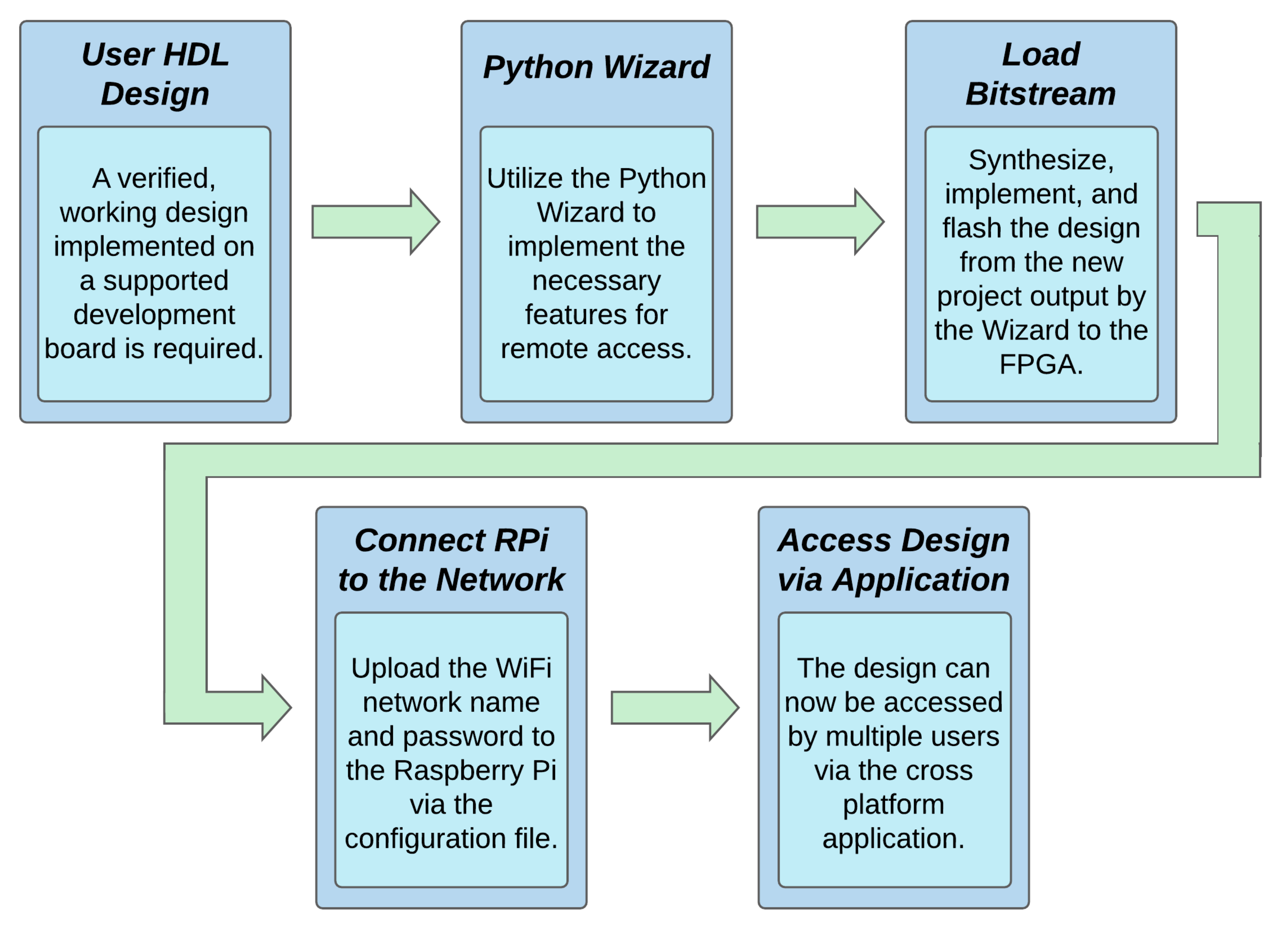
The remote access FPGA package is produced with all of the utilities required to quickly begin hosting FPGA interactivity on the Internet. The user would first have a hardware design that is compatible with one of the supported development boards, including an existing pinout. Next, the user would utilize the included Python Wizard, which implements the necessary hardware modules needed for remote access. The Python Wizard will output a copy of the user project that is now remote access ready. This new project is then synthesized, implemented, and flashed to the FPGA via the Quartus Application. For the final step, the user would copy a configuration file entitled “wpa_supplicant.conf” to the SD card with the necessary information to connect to the local WiFi network. The contents for the configuration file must be exactly as shown in Listing 1, with network_name being replaced with the name of the network, and network_password being replaced with the password of the network [22].
| Listing 1. Rasperry Pi network configuration file. |
 |
The design will then be ready for remote access from the included cross-platform application, which is described in Section 3.3. The design flow for implementing the remote access FPGA system can be seen in Figure 1.
3.2. System Architecture Design
The remote access FPGA system requires multiple hardware and software modules to function, including developments in Python, Typescript, Google Firebase [23], and Verilog HDL. With means for communicating user input and output values with the Raspberry Pi, the student module must work in conjunction with an interactivity hardware module. The interactivity module arranges for outputs from the student module to be packed into a bitstream to be sent to the Raspberry Pi, and simultaneously interprets incoming bitstreams as inputs for the student module. An interactivity module template, also referred to as the hardware wrapper, is designed, and the wrapper is modified by the Python Wizard so as to fit the design of the user’s module and copied into a new Quartus project along with a copy of the user project. The wizard further implements the necessary wires to drive the user defined signals from the interactivity module according to the serial inputs received from the Raspberry Pi. Similarly, the wires are also implemented from the user module to the interactivity module to drive the serial outputs to the FPGA. The interactivity module is further described in Section 3.6. The user module remains unmodified by the Python Wizard; it is only moved from being a top-level module to an embedded module in the wrapper, with the inputs and outputs now being driven by the interactivity module. The entire system architecture is shown in Figure 2, including the integration of the Raspberry Pi (RPi) and Google Firebase.
The Raspberry Pi grants the FPGA the ability to communicate with Google Firebase, which is a cloud-based system that manages the two-way communication between the Raspberry Pi and the mobile device. The mobile device—the remote user endpoint—allows for the interactivity between remote users and the physical FPGA. Google Firebase is the only portion of our work to have a one-to-many relationship with the user base. Each user application is communicating directly with Google Firebase, and any changes within the database are interpreted directly by the Raspberry Pi. There is only one data stream between a Raspberry Pi and Google Firebase at any time, regardless of the number of active users. This allows for our framework to scale directly with the user base, as the number of users who can access an FPGA remotely is limited only by the bandwidth restrictions from Google Firebase. Similarly, the amount of Remote FPGA projects that can be hosted is limited only by data constraints imposed by Google Firebase [23]. Each individual module is further described in later sections.
3.3. Mobile Application
The mobile application was developed via the Ionic development platform. Ionic increases application functionality by providing a cross-platform development environment that utilizes web-based programming languages, such as TypeScript. Once an application is developed through Ionic, the Ionic command line interface allows the designer to export the application to iOS and Android platforms. Further, Ionic formats all visuals, such as buttons, fonts, and text alignment to be consistent with each respective platform.
The mobile application implements various objects to display the binary FPGA pin values in real-time. The objects and their associated properties are modeled after the physical peripheral devices and pins and are shown in Table 1. Each object is assigned a ’name,’ which is used for identification within the application. Further, each object is also given a negative logic variable, which determines if it is using a pull up or pull down resistor network. Each peripheral is also assigned a pin object. The pin object an active listener to the Firebase Realtime Database, and is responsible for updating its parent peripherals depending on the values received from the database.
Further, the mobile application actively monitors the Google Firebase Realtime Database, specifically listening for any changes to an FPGA identified by the user. Upon the reception of a pin modification, the application updates the corresponding peripheral in the GUI.
3.4. Google Firebase Real-Time Database
Google Firebase is a real-time database, meaning that all changes are automatically updated to any program that has an active listener attached to that database. Google Firebase is an ideal candidate for the remote access FPGA application, as all changes from both the FPGA and mobile application must be immediately reflected on the opposite end of the data line. Further, Google Firebase relies on NoSQL, storing JavaScript Object Notation (JSON) objects rather than the typical Structured Query Language (SQL) table hierarchy. The default JSON object that is passed between the Raspberry Pi and mobile application through Google Firebase is shown in Figure 3.
Each individual FPGA is identified by the hardware ID located on the Raspberry Pi. This provides a unique key that the mobile application can use to request updates on pin values. Within each individual FPGA structure is the users self-denoted ID and the peripheral values the FPGA. The included pins in this structure are all pins from the FPGA General Purpose Input/Outputs (GPIOs), LEDs, seven segment displays, push buttons, and slide switches for the FPGA. All outputs are mutable from the Raspberry Pi, and all inputs are mutable from the user application. Latency results between the user endpoint application and physical FPGA device are summarized in Section 4.3.
3.5. Raspberry Pi to FPGA Interface
The Raspberry Pi model was selected with two key parameters in mind: Affordability and on-board WiFi. Very few pins are required for connection with the FPGA, so GPIO availability is not an issue with any Raspberry Pi model. With these two requirements, the ideal candidate is the Raspberry Pi Zero-W, a small version of the original Pi with a manufacturer’s suggested retail price (MSRP) of $10. The pin connections and signal names for the DE0-CV and DE2-115 development boards from Intel are described in Table 2. The DE0-CV and DE2-115 utilize Cyclone V and Cyclone IV-E FPGAs from Intel, respectively. Further, the development boards have peripherals that allow the user to interact with the FPGA without the need for any additional circuit building, such as LEDs, slide switches, and push buttons. These peripherals are deactivated when the remote FPGA wrapper is in use, as the peripherals are accessed via the mobile application instead. Both of the aforementioned development boards were utilized for testing purposes with the remote FPGA wrapper.
The benefit of serializing the data from the FPGA is that there are only three data connections from the Raspberry Pi, despite the management of all of the input and output signals from the FPGA. This is accomplished by encoding the pin values for the user-selected board and transmitting them over UART to the Raspberry Pi.
With means to transmit pin changes for both inputs and outputs, data including the modified pin along with the new pin value must be sent back and forth between the Raspberry Pi and FPGA. Pin values for various development boards are extracted from a local JSON file loaded on the Raspberry Pi, and the correct file is loaded based on configuration data that is loaded to the FPGA via the compilation wizard. Once the pins have been extracted, they are sorted alphabetically and enumerated in binary values. Binary pin values for the DE0-CV board are shown in Table 3.
3.6. Remote FPGA Hardware Wrapper
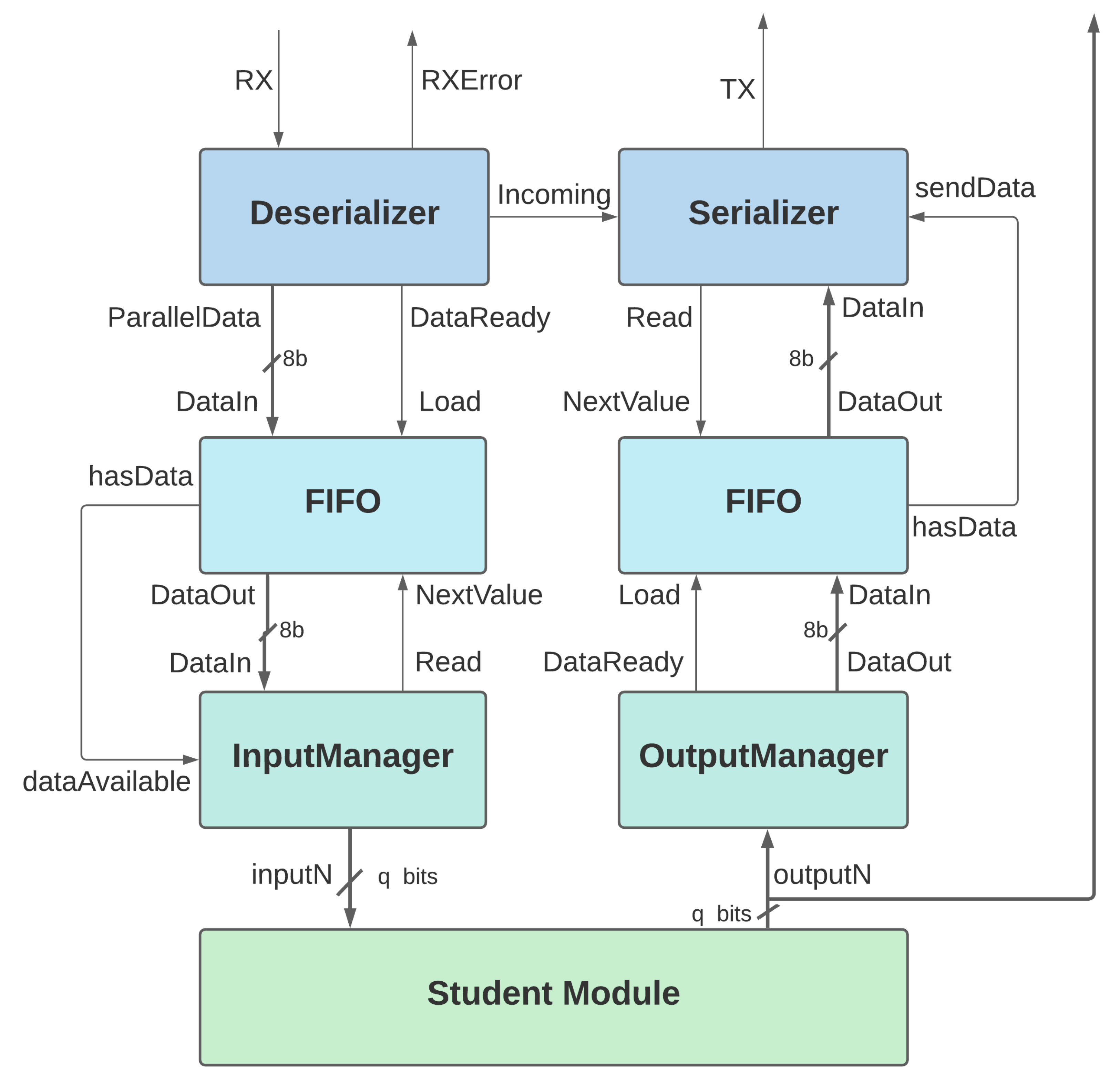
The Python Wizard embeds the user design into the Remote FPGA Hardware Wrapper. The abstract FPGA system diagram is shown in Figure 4.
To account for the relatively slow read and write times of the Serializer/Deserializer (SerDes) module, a First In, First Out Buffer (FIFO) is put in place to hold data during transmit/receive procedures. The FIFO is a configurable buffer that will hold data until it can be used. Data are loaded into the buffer such as a queue: new data are loaded at the back of the queue, and when new data are requested from the buffer, the oldest data are retrieved. Both FIFOs are configured with an 8-bit width. The FIFO on the input side has a depth of 16 words and the FIFO on the output side has a depth of 64 words.
The Input Manager module is one of the modules that must be compiled via the Python Wizard. Depending on the amount of user inputs detected from the top module to be embedded into the system for remote access, the Input Manager will have the same exact corresponding outputs. For example, if the embedded module has five input signals with a width of four bits, the Input Manager will have a generated five outputs with width four bits. In this manner, as the Input Manager receives an updated user input from the FIFO, it will decode the pin value from the most significant seven bits, and then set the corresponding signal to the value in the least significant bit. It will continue this cycle as long as the FIFO is not empty.
Similar to the Input Manager, the Output Manager handles all of the embedded FPGA module outputs. The Output Manager has a corresponding input wire for each output of the embedded student module. The Output Manager then encodes the signal based on the pin assignment for that signal. The encoding of the signal is determined by the Python Wizard via a JSON file. For example, if the FPGA toggles an output on a wire that is assigned to pin AA15 to a logic high, from Table 3 we can determine that the encoded value will be 8’b00010001. This is done by taking the pin value from the table, 7’b0001000, and concatenating it with a single bit value of 1, which represents the logical value that should be assigned to the pin. This data is then output to a FIFO so it can be transmitted to the Raspberry Pi.
The embedded student module is a user defined module, which is embedded into the Remote FPGA framework when the Python Wizard is run. This is the module that users will view on the mobile application. Both inputs and outputs are determined by the user design. All inputs are wired to the Input Manager, with the exceptions of system clocks. The system clocks are wired through the top-level module through to the embedded module. Outputs are both wired to the Output Manager and exposed on the top-level module so that they may be viewed on the mobile application as well as the physical FPGA device.
3.7. Python Compiler Wizard
The embedded module signals must be adapted to fit the remote access top module. One could do this manually, but it is a long and meticulous procedure that should be automated. For this reason, the Python Wizard was developed. The information required by the Python Wizard includes the project folder destination, the destination for the new, remote-enabled project, the user .qsf constraint file, the user source code location, and the name of the top module. The Python Wizard then creates the inputs and outputs for the interactivity module from a template file as needed relative to the top-module from the user. Next, the tool embeds the original top module into the generated interactivity module. Instead of overwriting the user project, the Python Wizard creates a new folder and project with the remote-access implementation.
The Python Wizard utilizes the basic user interface features of the tkinter library from Python. There are some basic input checks built into the wizard, such as confirming the folder locations and the correct file extensions. Once the build has been completed, the user can open the new Quartus project, recompile, and flash the FPGA with their new remote access-enabled project. The tool is limited in that it only works with HDL top modules that are implemented via Verilog. Other than this sole requirement, the user does not need to follow any other guidelines. The Python Wizard is robust enough to detect the signal width and direction regardless of where it was defined in the code. As long as the original design is robust enough to synthesize prior to the implementation of the hardware wrapper, the Python Wizard will succeed in integration remote functionality.
4. Results
4.1. Experimental Results
By utilizing the Ionic platform, we are able to successfully implement a GUI for interacting with the FPGA remotely via a variety of mobile and PC devices. The devices include PCs, Macs, devices utilizing iOS, and devices utilizing Android OS. Further, the application interface allows for users to interact with one another via the same FPGA lab simultaneously, regardless of the platform that each user is utilizing. For example, a user with iOS devices, a user with a PC, and a user with an Android device can all interact with the same lab simultaneously.
When the user first opens the remote access FPGA application, they are greeted by a server browser page that lists all of the available FPGA devices for connectivity. Any FPGA that is connected to Google Firebase via the Raspberry Pi will be displayed here by ID number. Upon selecting a device, the user will be taken to the emulation screen for their selected FPGA.
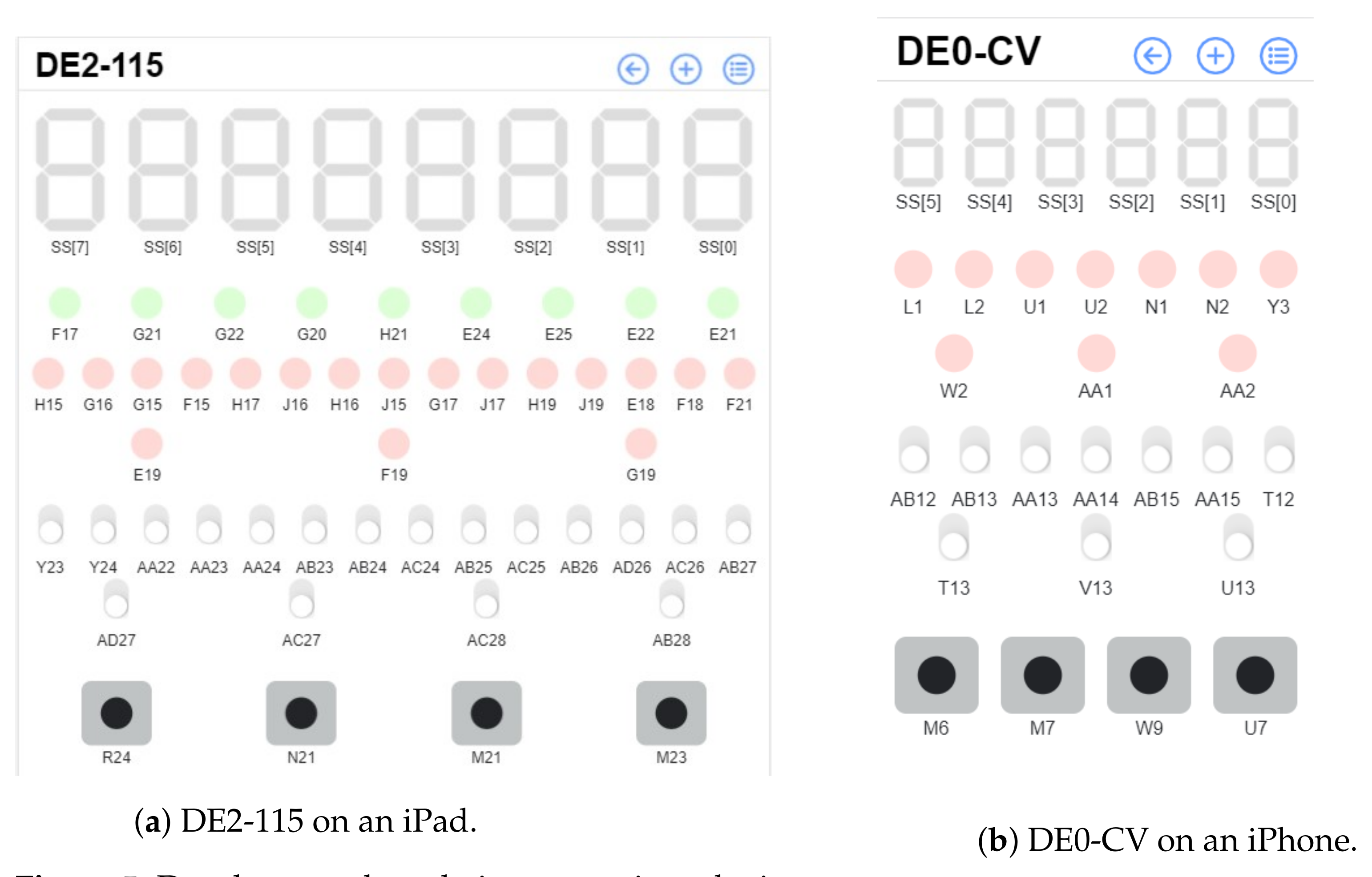
The layout is loaded from Firebase, which is stored on the Raspberry Pi in a JSON file. All input and output peripherals that are by default on the physical board are listed in the device view. The DE2-115 development board from Intel is shown in Figure 5a, and the DE0-CV development board from Intel is shown in Figure 5b.
As can be seen in both views, all development board peripherals are displayed. The seven segment displays are shown at the top, labeled as SS[x]. The LEDs are shown below, labeled by their default pin connection. Below those are the slide switches, again labeled by their pin connects. The last set of on-board peripherals, the push buttons, are shown at the very bottom. All connected users can interact with the design. This is to encourage collaboration between students and teaching assistants during the presentation of a project. All user inputs are sequenced, and the input that is last received by the Raspberry Pi server will be the one reflected on the FPGA as all inputs are sequentially loaded into a FIFO. Further, three buttons can be seen in the menu toolbar. They are, in order from left to right: the back button, the add peripheral button, and the list peripheral button.
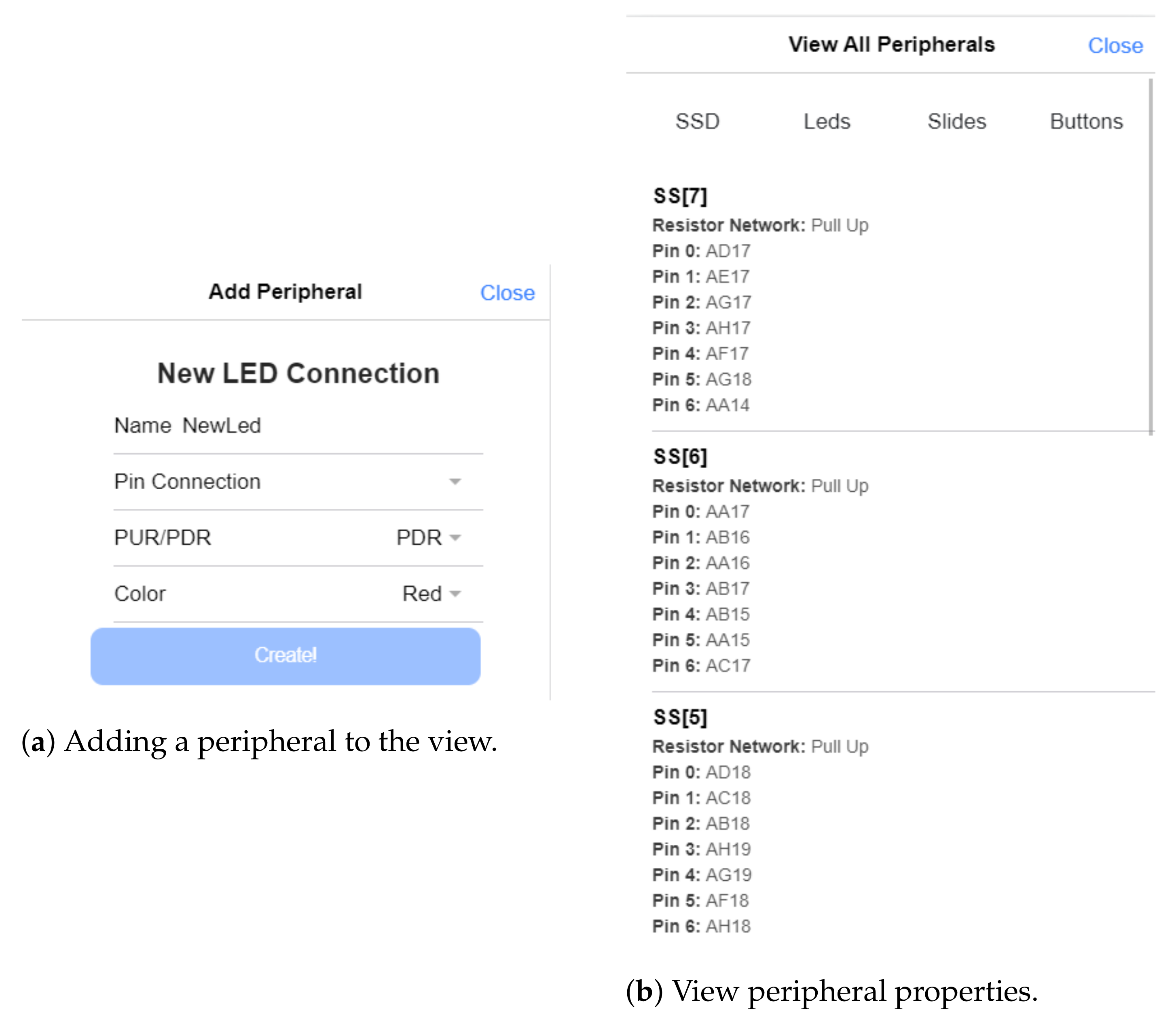
The back button simply allows the user to exit the view for the current FPGA and return to the FPGA server select screen. The add peripheral button will allow the user to add a new input or output to a GPIO pin located on the development board. This functionality can be seen in Figure 6a. For this new peripheral to work, the GPIO pin must be assigned to a signal in the original Quartus project before the remote connectivity wrapper is added to the project. All LEDs are grouped according to their color: red, green, and miscellaneous. The rows will wrap to the next row if their length exceeds with width of the viewport.
One additional feature of the view FPGA screen is that all interactions from other users on an application connected to the FPGA are seen in real-time. For example, if a user holds down the button at pin U7, the button will be shown as pressed in the live view for all other users connected to the same FPGA server. This is to further emulate an environment where all users are working on the same project in the same room.
The view peripheral button, shown as the list icon in the menu toolbar, is particularly useful as it lists the properties, including the assigned pin, for each displayed peripheral device. Further, this is where a user can go to remove a device from the view. Within the view peripheral screen, users can select which type of devices they would like to examine by type: LED, slide switch, seven segment display, or push button. This functionality is shown in Figure 6b. By swiping left on a peripheral, a delete button is exposed which can then be used to remove that peripheral from the display.
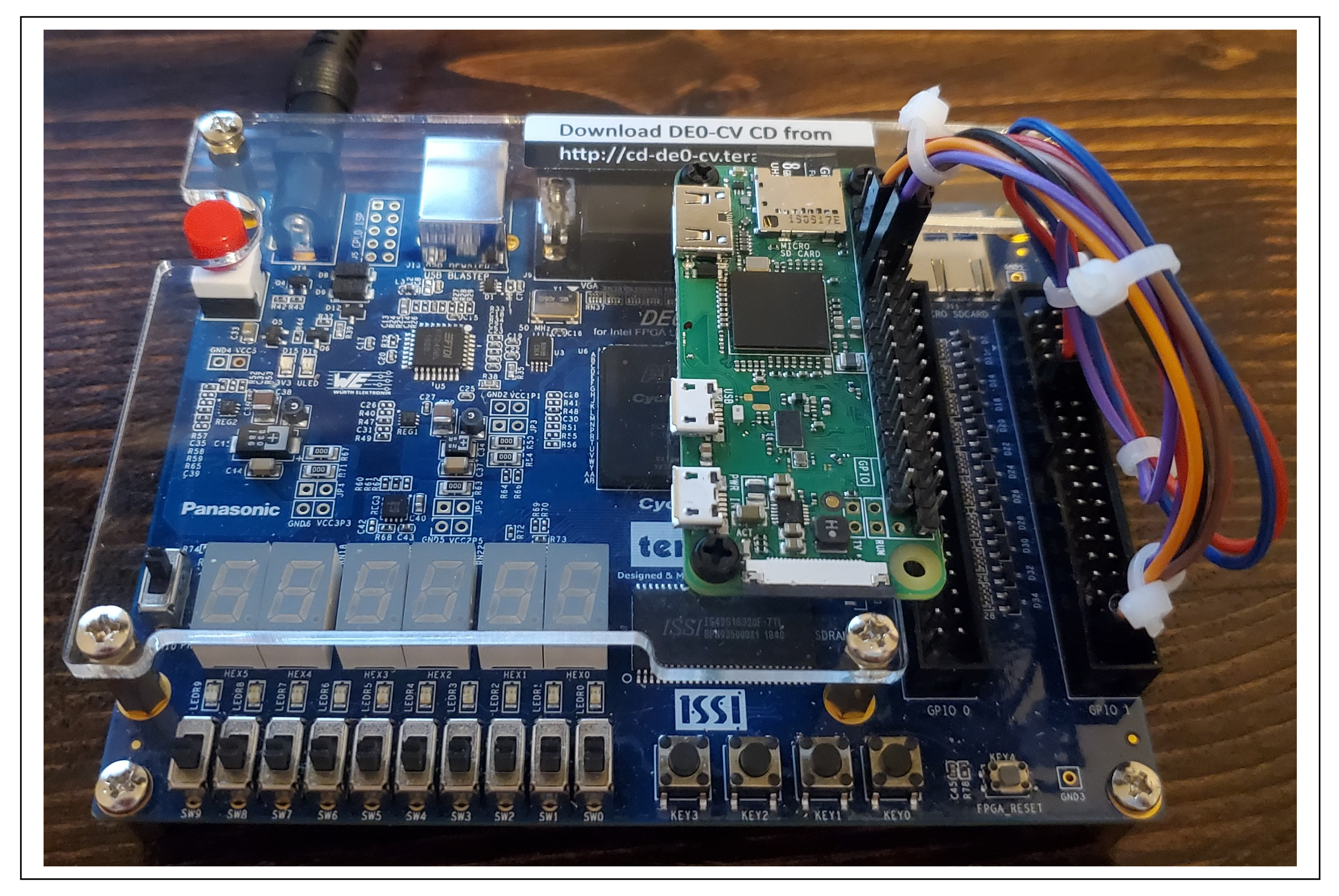
The lowest-cost experimental result consists of a DE0-CV development board, which implements a Cyclone V FPGA, and a Raspberry Pi Zero. The total academic cost for the system is $110 at the time of the writing. An image of the Raspberry Pi/DE0-CV combination can be seen in Figure 7.
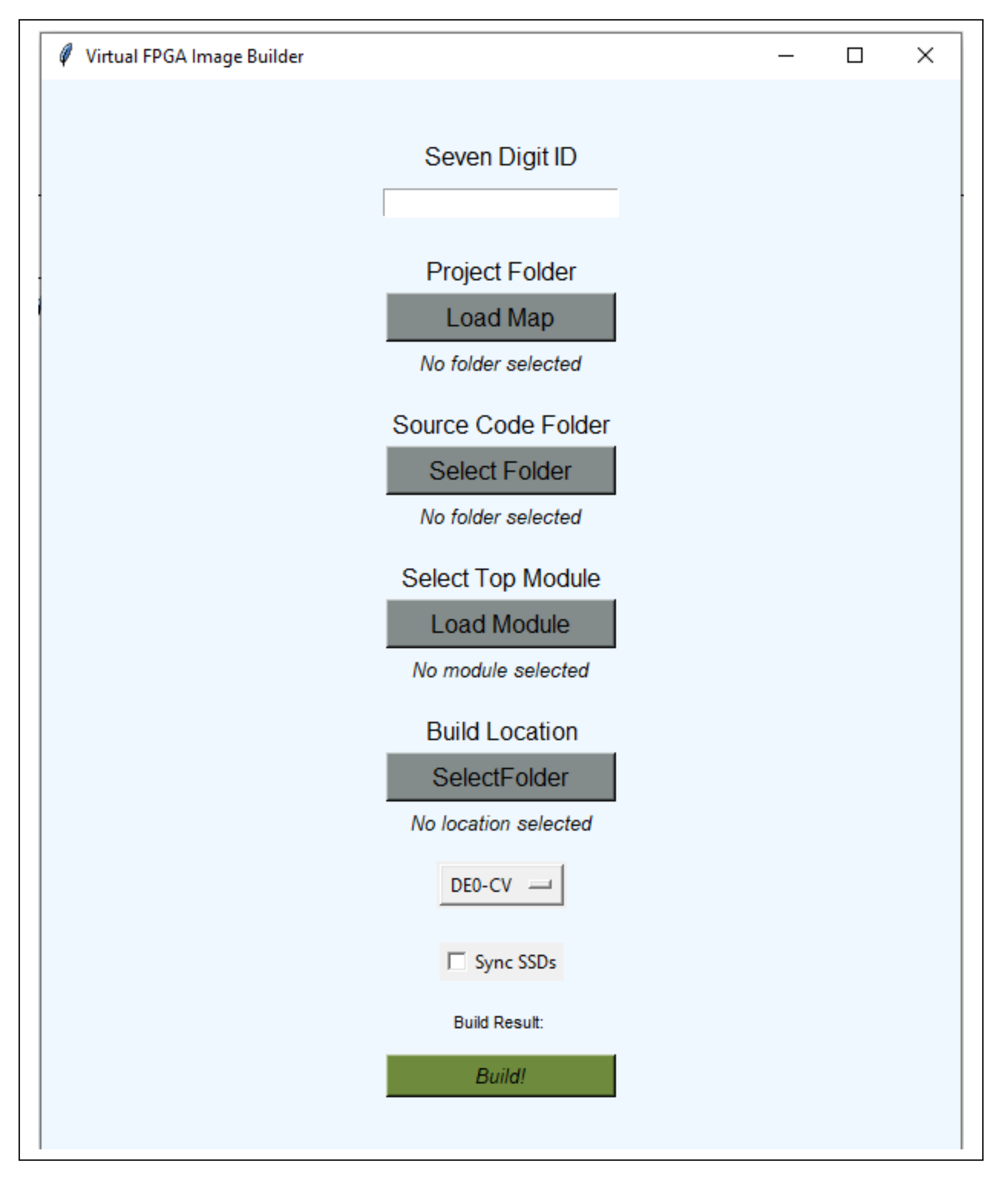
The Python Wizard is essential for incorporating a student lab with the remote IoT capabilities. The Python wizard requires seven inputs: the user ID, the Quartus project folder, the Verilog source code folder, the top module for the project, the folder to put the newly built Quartus project, the target development board, and an option to sync the seven segment display updates. If the Sync SSD box is left unchecked, the displays will update on the GUI one bit at a time. Any errors along the way will be displayed under “Build Result”; otherwise, “Build Completed!” will be displayed. The GUI for the Python Wizard can be seen Figure 8.
4.2. Resource Usage
The remote FPGA hardware wrapper was designed to be as lightweight as possible, so as not to utilize a large amount of resources on the physical FPGA. This is pertinent as the hardware wrapper for remote applications must utilize as little hardware as possible so as to allow the user to develop a complex hardware model without limiting resources. Resource utilization for various FPGA chip sets is shown in Table 4. Adaptive Logic Modules (ALMs) are the fundamental building block on Intel FPGAs, as they are composed of two or more look up tables (LUTs) that are used to implement the user-designed digital logic [24]. It is key to note that in the remote FPGA application, the hardware wrapper utilizes less than 1% of available ALMs on the tested platforms. This is ideal for a light-weight development platform such as the remote-access tool. The final synthesis report can be seen in Figure 9.
4.3. Latency
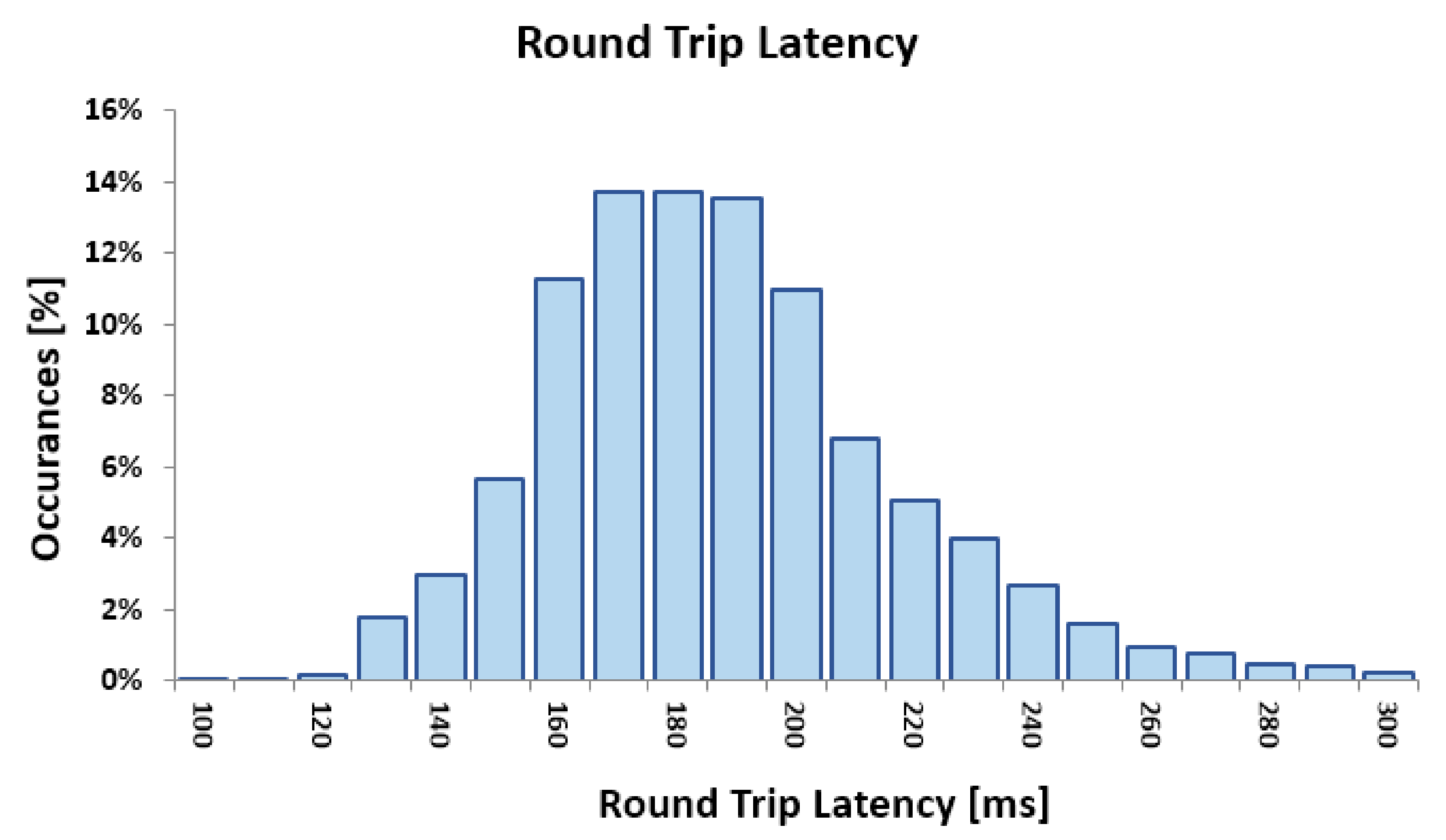
As FPGAs are performing time-critical processing tasks, latency between a remote FPGA and a user application is a critical component for correctly interpreting inputs and outputs from the FPGA. With means to measure round-trip data latency between the user application and FPGA, we timed data as it traveled from the UI input application to the FPGA for processing, and back again to the application. A lightweight hardware module was loaded to the DE0-CV board in which an output LED was assigned to an input switch, so that the data were immediately reflected in the user application upon reception of an input.
The latency test began timing data transmission upon the flip of a slide switch via the user interface, and ended when the application realized the corresponding updated LED pin. This test was run 10,000 times. The results are displayed in a histogram, displayed in Figure 10, and the statistics are summarizes in Table 5. The updated pin values are reflected in the user application asynchronously, that is, reading from one pin value does not delay reading from another pin value.
4.4. Discussion
The remote FPGA platform we have developed provides a modern approach when compared to other remote lab methods [2,3,7]. By utilizing the Ionic development platform, we are able to open up convenient, mobile access to students. Students can access and harness the power of an FPGA using a personal mobile device to access their remote FPGA project as opposed to having to access via a PC. Further, our approach utilizes cloud applications for communicating changes on the FPGA, similar to Gophane et al. [20]. By introducing communication via the cloud, we are able to eliminate the need for a webcam, in turn reducing the overall cost, network usage, and setup time of the system. This is beneficial for both university engineering departments and their respective students, as reduced costs increases the ability to scale the system, and in turn, increases accessibility for students.
Our novel design also opens up the possibility for collaboration on student projects by allowing multiple users to access the same remote lab simultaneously. As opposed to single user access [2,3,4,5,6,7], simultaneous access capability enables collaboration, project presentation for online classes, and remote grading capabilities for teaching assistants. As each user application accesses the cloud instead of directly accessing the FPGA, there can be an unlimited amount of users for a single FPGA without reducing quality due to bandwidth restrictions.
Further, the remote access FPGA allows users to expand upon the development possibilities of an FPGA that our methodology utilizes by giving the users the ability to add and remove unnecessary peripheral devices. For example, if a student were to decide on the classical red–yellow–green stoplight lab, the remote FPGA application gives that student the ability to add additional multi-color LEDs and push buttons necessary to complete their project. This can all be done without incurring the financial cost of buying the physical peripheral or going through the process of setting up a physical resistor network, allowing the students to focus on the digital design aspect of the lab as opposed to the set up of electronic components.
Future directions for our proposed work are still being explored as well. The remote FPGA system was designed to scale, as the hardware wrapper is portable between FPGA manufacturers and the peripherals displayed in the applications are loaded via a modifiable JSON-file. By adding other JSON files that include peripheral information and pin connections for other development boards, we can quickly expand the mobile application to include other FPGA board types.
5. Conclusions
In this work, we proposed an IoT solution for remote digital design laboratories. We presented a system architecture which includes a cross-platform web application, Google Firebase access, Raspberry Pi, and a host FPGA device. Our novel design is unique from other works in that it allows multiple users to collaborate remotely on one FPGA, which is useful for debugging, classroom-style presentations, and group projects. The hardware application programming interface (API) wrapper can be added to any FPGA project with a Python Wizard, significantly reducing setup times for remote access. The hardware wrapper requires less than 1% of hardware resources on tested FPGA chips, and data latency from the application to the FPGA and back has a round trip time of an average of 196 ms. This delay is an acceptable rate, as it is a near instantaneous response to user input. Our design was developed using the DE0-CV and DE2-115 boards from Intel, but can easily replicate the peripheral devices of other development board with the use of an updated JSON file. Our future plans for this work include adding more JSON board support files for Intel based development boards. Further, we are aiming to add a password protection feature to the user application to prevent unauthorized users from accessing student projects.
Author Contributions
Conceptualization, Y.C.; methodology, A.M. and Y.C.; software, A.M.; validation, A.M.; formal analysis, A.M.; investigation, A.M. and Y.C.; writing—original draft preparation, A.M.; writing—review and editing, A.M. and Y.C.; visualization, A.M.; supervision, Y.C.; All authors have read and agreed to the published version of the manuscript.
Funding
This research received no external funding.
Conflicts of Interest
The authors declare no conflict of interest.
Abbreviations
The following abbreviations are used in this manuscript:
| FPGA | Field-Programmable Gate Array |
| RPi | Raspberry Pi Zero |
| UART | Universal Asynchronous Receiver Transmitter |
| FIFO | First In, First Out |
| SerDes | Serializer Deserializer |
| IoT | Internet of Things |
| JSON | Java Script Object Notation |
| ALM | Adaptive Logic Module |
References
- Marinoni, G.; Van’t Land, H.; Jensen, T. The Impact of Covid-19 on Higher Education around the World. Available online: https://www.iau-aiu.net/IMG/pdf/iau_covid19_and_he_survey_report_final_may_2020.pdf (accessed on 9 September 2021).
- Hashemian, R.; Riddley, J. FPGA e-Lab, a technique to remote access a laboratory to design and test. In Proceedings of the 2007 IEEE International Conference on Microelectronic Systems Education (MSE’07), San Diego, CA, USA, 3–4 June 2007; pp. 139–140. [Google Scholar]
- Morgan, F.; Cawley, S.; Callaly, F.; Agnew, S.; Rocke, P.; O’Halloran, M.; Drozd, N.; Kepa, K.; McGinley, B. Remote FPGA lab with interactive control and visualisation interface. In Proceedings of the 2011 21st International Conference on Field Programmable Logic and Applications, Chania, Greece, 5–7 September 2011; pp. 496–499. [Google Scholar]
- Mohsen, A.E.R.; GadAlrab, M.Y.; Elhaya, M.Z.; Alshaer, G.; Asy, M.; Mostafa, H. Remote FPGA lab for ZYNQ and virtex-7 kits. In Proceedings of the 2019 IEEE 62nd International Midwest Symposium on Circuits and Systems (MWSCAS), Dallas, TX, USA, 4–7 August 2019; pp. 185–188. [Google Scholar]
- Schwandt, A.; Winzker, M. Make it open-Improving usability and availability of an FPGA remote lab. In Proceedings of the 2019 IEEE Global Engineering Education Conference (EDUCON), Dubai, United Arab Emirates, 8–11 April 2019; pp. 232–236. [Google Scholar]
- Oballe-Peinado, Ó.; Castellanos-Ramos, J.; Sánchez-Durán, J.A.; Navas-González, R.; Daza-Márquez, A.; Botín-Córdoba, J.A. FPGA-Based Remote Laboratory for Digital Electronics. In Proceedings of the 2020 XIV Technologies Applied to Electronics Teaching Conference (TAEE), Porto, Portugal, 8–10 July 2020; pp. 1–5. [Google Scholar]
- Fujii, N.; Koike, N. IoT remote group experiments in the cyber laboratory: A FPGA-based remote laboratory in the hybrid cloud. In Proceedings of the 2017 International Conference on Cyberworlds (CW), Chester, UK, 20–22 September 2017; pp. 162–165. [Google Scholar]
- Nasri Sulaiman, Z.A.O.; Marhaban, M.; Hamidon, M. Design and implementation of FPGA-based systems-a review. Aust. J. Basic Appl. Sci. 2009, 3, 3575–3596. [Google Scholar]
- Upegui, A.; Sanchez, E. Evolving hardware by dynamically reconfiguring Xilinx FPGAs. In Proceedings of the International Conference on Evolvable Systems, Sitges, Spain, 12–14 September 2005; pp. 56–65. [Google Scholar]
- Al-Safi, A.; Al-Khayyat, A.; Manati, A.M.; Alhafadhi, L. Advances in FPGA Based PWM Generation for Power Electronics Applications: Literature Review. In Proceedings of the 2020 11th IEEE Annual Information Technology, Electronics and Mobile Communication Conference (IEMCON), Vancouver, BC, Canada, 4–7 November 2020; pp. 0252–0259. [Google Scholar]
- Rasoulinezhad, S.; Boland, D.; Leong, P.H. MLBlocks: FPGA Blocks for Machine Learning Applications. In Proceedings of the 2021 ACM/SIGDA International Symposium on Field-Programmable Gate Arrays, Monterey, CA, USA, 27 February–1 March 2021; p. 228. [Google Scholar]
- Wang, X.; Li, C.; Song, J. Motion image processing system based on multi core FPGA processor and convolutional neural Network. Microprocess. Microsyst. 2021, 82, 103923. [Google Scholar] [CrossRef]
- Liu, P.; Qingqing, W.; Liu, W. Enterprise human resource management platform based on FPGA and data mining. Microprocess. Microsyst. 2021, 80, 103330. [Google Scholar] [CrossRef]
- Elnawawy, M.; Farhan, A.; Al Nabulsi, A.; Al-Ali, A.; Sagahyroon, A. Role of FPGA in Internet of Things Applications. In Proceedings of the 2019 IEEE International Symposium on Signal Processing and Information Technology (ISSPIT), Ajman, United Arab Emirates, 10–12 December 2019; pp. 1–6. [Google Scholar]
- Kang, S.; Moon, J.; Jun, S. FPGA-Accelerated Time Series Mining on Low-Power IoT Devices. In Proceedings of the 2020 IEEE 31st International Conference on Application-specific Systems, Architectures and Processors (ASAP), Manchester, UK, 6–8 July 2020; pp. 33–36. [Google Scholar] [CrossRef]
- Ferdian, R.; Aisuwarya, R.; Erlina, T. Edge Computing for Internet of Things Based on FPGA. In Proceedings of the 2020 International Conference on Information Technology Systems and Innovation (ICITSI), Bandung, Indonesia, 16–17 November 2020; pp. 20–23. [Google Scholar]
- Sung, G.M.; Lee, C.T.; Chen, C.R. IoT-Based Home Care System with a FPGA Development Board by Using RS-485 Interface and Verilog HDL. In Proceedings of the 2020 IEEE International Conference on Systems, Man and Cybernetics (SMC), Toronto, ON, Canada, 11–14 October 2020; pp. 3370–3374. [Google Scholar]
- Peng, L.; Xin, Z.; Ping, G. Design and Implementation of Remote DeepFace Model Face Recognition System Based on sbRIO FPGA Platform and NB-IOT Module. In Proceedings of the 2019 2nd International Conference on Safety Produce Informatization (IICSPI), Chongqing, China, 28–30 November 2019; pp. 505–509. [Google Scholar]
- Wang, S.; Hou, Y.; Gao, F.; Ji, X. A novel IoT access architecture for vehicle monitoring system. In Proceedings of the 2016 IEEE 3rd World Forum on Internet of Things (WF-IoT), Reston, VA, USA, 12–14 December 2016; pp. 639–642. [Google Scholar]
- Gophane, K.C.; Bhaskar, P. FPGA Based Adaptive IoT Framework for Distinct Applications. In Proceedings of the 2018 Fourth International Conference on Computing Communication Control and Automation (ICCUBEA), Pune, India, 16–18 August 2018; pp. 1–6. [Google Scholar]
- Brasilino, L.R.; Swany, M. Low-Latency CoAP Processing in FPGA for the Internet of Things. In Proceedings of the 2019 International Conference on Internet of Things (iThings) and IEEE Green Computing and Communications (GreenCom) and IEEE Cyber, Physical and Social Computing (CPSCom) and IEEE Smart Data (SmartData), Atlanta, GA, USA, 14–17 July 2019; IEEE: New York, NY, USA, 2019; pp. 1057–1064. [Google Scholar]
- Raspberry Pi Ltd. Raspberry Configuration Documentation. Available online: https://www.raspberrypi.org/documentation/computers/configuration.html (accessed on 9 September 2021).
- Google. Google Firebase Documentation. Available online: https://firebase.google.com/docs/database/usage/limits (accessed on 9 September 2021).
- Intel Altera. FPGA Architecture. Available online: https://www.intel.com/content/dam/www/programmable/us/en/pdfs/literature/wp/wp-01003.pdf (accessed on 9 September 2021).
Figure 1.
The required design flow for implementing remote access into a design.

Figure 2.
The remote access FPGA system architecture.

Figure 3.
Google Firebase real-time database architecture.

Figure 4.
The FPGA architecture required for user module interaction.

Figure 5.
DE2-115 on an iPad.

Figure 6.
Adding a peripheral to the view.

Figure 7.
The Raspberry Pi in conjunction with the DE0-CV development board.

Figure 8.
The Python Wizard GUI.

Figure 9.
The synthesis report of the FPGA hardware wrapper for remote operation on a DE0-CV development board.
Figure 9.
The synthesis report of the FPGA hardware wrapper for remote operation on a DE0-CV development board.

Figure 10.
Histogram summarizing the round-trip data latency results.


Table 1.
Various class implementations in the user application.
| Class | Properties |
|---|---|
| SevenSegment | Name: String NegativeLogic: Bool SegmentImage: String Pins: Array<Pin> |
| LED | Name: String NegativeLogic: Bool LEDImage: String PinConnect: Pin |
| Slide | Name: String NegativeLogic: Bool PinConnect: Pin Flipped: Bool |
| PushButton | Name: String NegativeLogic: Bool PinConnect: Pin Depressed: Bool |
| Pin | Assignment: String Direction: Int Value: Int Parent: Array<Peripheral> |
Table 2.
Raspberry Pi pin connects.
| Raspberry Pi Pin | DE0-CV Pin | DE2-115 Pin | Signal Name | Signal Description |
|---|---|---|---|---|
| 2 | 5V | 5V | 5[V] Power | Five-volt power supply. |
| 6 | Gnd | Gnd | Ground | Common ground. |
| 7 | J17 | AH23 | Reset | Software controlled FPGA reset. |
| 8 | G12 | AH26 | R-Pi UART TX | Serial transmit line. |
| 10 | K16 | AG26 | R-Pi UART RX | Serial receive line. |
| 11 | G15 | AG23 | UART Error | Active high upon transmission error. |
Table 3.
DE0-CV Pins and their corresponding 7-bit reference value.
| Pin # | Pin | Pin # | Pin | Pin # | Pin | Pin # | Pin |
|---|---|---|---|---|---|---|---|
| 0000000 | A12 | 0100000 | D13 | 1000000 | M18 | 1100000 | U1 |
| 0000001 | A13 | 0100001 | D17 | 1000001 | M20 | 1100001 | U13 |
| 0000010 | A14 | 0100010 | E14 | 1000010 | M21 | 1100010 | U15 |
| 0000011 | A15 | 0100011 | E15 | 1000011 | M6 | 1100011 | U16 |
| 0000100 | AA1 | 0100100 | E16 | 1000100 | M7 | 1100100 | U17 |
| 0000101 | AA10 | 0100101 | F12 | 1000101 | M8 | 1100101 | U2 |
| 0000110 | AA13 | 0100110 | F13 | 1000110 | N1 | 1100110 | U20 |
| 0000111 | AA14 | 0100111 | F14 | 1000111 | N19 | 1100111 | U21 |
| 0001000 | AA15 | 0101000 | F15 | 1001000 | N2 | 1101000 | U22 |
| 0001001 | AA17 | 0101001 | G11 | 1001001 | N20 | 1101001 | U7 |
| 0001010 | AA18 | 0101010 | G13 | 1001010 | N21 | 1101010 | V13 |
| 0001011 | AA19 | 0101011 | G16 | 1001011 | N9 | 1101011 | V14 |
| 0001100 | AA2 | 0101100 | G17 | 1001100 | P14 | 1101100 | V16 |
| 0001101 | AA20 | 0101101 | G18 | 1001101 | P16 | 1101101 | V18 |
| 0001110 | AA22 | 0101110 | H10 | 1001110 | P17 | 1101110 | V19 |
| 0001111 | AB12 | 0101111 | H14 | 1001111 | P18 | 1101111 | V20 |
| 0010000 | AB13 | 0110000 | H18 | 1010000 | P19 | 1110000 | V21 |
| 0010001 | AB15 | 0110001 | J11 | 1010001 | P9 | 1110001 | W16 |
| 0010010 | AB17 | 0110010 | J13 | 1010010 | R15 | 1110010 | W19 |
| 0010011 | AB18 | 0110011 | J18 | 1010011 | R16 | 1110011 | W2 |
| 0010100 | AB20 | 0110100 | J19 | 1010100 | R17 | 1110100 | W21 |
| 0010101 | AB21 | 0110101 | K17 | 1010101 | R21 | 1110101 | W22 |
| 0010110 | AB22 | 0110110 | K19 | 1010110 | R22 | 1110110 | W9 |
| 0010111 | B12 | 0110111 | K20 | 1010111 | T12 | 1110111 | Y14 |
| 0011000 | B13 | 0111000 | K21 | 1011000 | T13 | 1111000 | Y15 |
| 0011001 | B15 | 0111001 | K22 | 1011001 | T14 | 1111001 | Y16 |
| 0011010 | B16 | 0111010 | L1 | 1011010 | T15 | 1111010 | Y17 |
| 0011011 | C1 | 0111011 | L17 | 1011011 | T17 | 1111011 | Y19 |
| 0011100 | C13 | 0111100 | L18 | 1011100 | T18 | 1111100 | Y20 |
| 0011101 | C15 | 0111101 | L19 | 1011101 | T19 | 1111101 | Y21 |
| 0011110 | C16 | 0111110 | L2 | 1011110 | T20 | 1111110 | Y22 |
| 0011111 | C2 | 0111111 | L8 | 1011111 | T22 | 1111111 | Y3 |
Table 4.
Resource usage for various FPGA chipsets.
| FPGA Device | ALM Utilization |
|---|---|
| DE-0 Dev Board | 141 (<1%) |
| DE2-115 Dev Board | 342 (<1%) |
| Cyclone VE Dev Board | 271 (<1%) |
| Cyclone V SoC Dev Kit | 265 (<1%) |
| Arrow SoCKit | 267 (<1%) |
Table 5.
Server input/output response time test results.
| Statistic | Value |
|---|---|
| Total Tests n | 10,000 |
| Maximum | 6050 [ms] |
| Minimum | 2.75 [ms] |
| Results greater than 1 [s] | 0.38% |
| Results less than 0.2 [s] | 74% |
| Population Mean | 196 [ms] |
| Standard Deviation | 112 [ms] |
Publisher’s Note: MDPI stays neutral with regard to jurisdictional claims in published maps and institutional affiliations. |
© 2021 by the authors. Licensee MDPI, Basel, Switzerland. This article is an open access article distributed under the terms and conditions of the Creative Commons Attribution (CC BY) license (https://creativecommons.org/licenses/by/4.0/).
Share and Cite
MDPI and ACS Style
Magyari, A.; Chen, Y. FPGA Remote Laboratory Using IoT Approaches. Electronics 2021, 10, 2229. https://doi.org/10.3390/electronics10182229
AMA Style
Magyari A, Chen Y. FPGA Remote Laboratory Using IoT Approaches. Electronics. 2021; 10(18):2229. https://doi.org/10.3390/electronics10182229
Chicago/Turabian StyleMagyari, Alexander, and Yuhua Chen. 2021. "FPGA Remote Laboratory Using IoT Approaches" Electronics 10, no. 18: 2229. https://doi.org/10.3390/electronics10182229
Note that from the first issue of 2016, this journal uses article numbers instead of page numbers. See further details here.