
Abstract
A scalable concept to prepare high current density windings with high-temperature superconducting material is introduced. The concept covers miniaturized high-current windings and large coils for applications in energy technology as well. The principle is based on a circular disk-up-down-assembly ('DUDA') and extended to rectangular coils. First measurements on the assemblies (≈40 turns) in liquid nitrogen are presented as a proof-of-concept. Centre fields of ≈40 mT and ≈340 mT are measured during steady operation and pulsed operation respectively. Operating the assemblies at lower temperatures will strongly increase the current and field performance. Lowering the contact resistance might lead to further improvements. Due to the homogenous structure in the radial direction, shear stresses are minimized and large winding heights can be realized in principle. The DUDA concept of coil windings can be used to build even more sophisticated magnetic arrangements, e.g. Halbach-arrays, or complex windings for new stator configurations of rotating machines. The optional miniaturization offers compact and powerful magnets, e.g. for accelerators too.
Export citation and abstract BibTeX RIS

Original content from this work may be used under the terms of the Creative Commons Attribution 4.0 license. Any further distribution of this work must maintain attribution to the author(s) and the title of the work, journal citation and DOI.
1. Introduction
An early promise of high-temperature superconductors (HTSs) is the generation of high magnetic fields and recent developments in hybrid magnets using 2G-HTS [1], bulk HTS [2] as well as developments in the field and direction of NMR [3, 4] have demonstrated this possibility. However, building large magnets and windings is frequently limited by stresses: on the one hand by hoop stress proportional to radius and current density, and on the other by shear stresses resulting from the sequence of different materials and CTE's in the radial direction [5, 6]. To handle these stresses, a homogeneous architecture in the radial direction would be highly beneficial when building magnets.
Furthermore, the required volume of high magnetic field in many cases is quite limited, so sophisticated approaches to build compact magnets with small bores are of value. An early work considered magnetized HTS bulk annuli [7] to realize that, but the mechanical strength was weak. Other groups studied HTS tapes instead of bulks similar to permanent magnets [8] and in the field of rotating machines [9]. However, all these approaches have in common that once magnetized the remnant field is hard to deliberately change.
The highest magnetic fields produced by normal-conducting magnets are based on a Bitter-winding architecture [10, 11] using a stack of slit homogenous Cu-alloy disks separated by insulation and dedicated contact areas.
In this study, we describe the realization of a similar concept (disk-up-down assembly 'DUDA') to produce high-magnetic fields by compact circular and rectangular 2G-HTS based assemblies, which are operated by an adjustable excitation current. First proof-of-principles are performed and options for application in magnet technology and power engineering are given, e.g. by drop-in solutions for conventional rare-earth permanent magnets.
2. Materials and methods
2.1. General concept
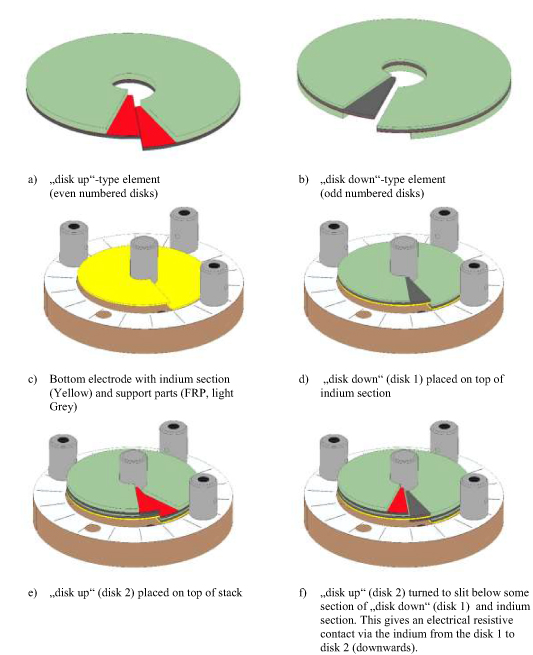
The basic idea was to replace well established coil windings based on a multitude of turns of 2G-HTS tape (either planar circular or racetrack coils) by an assembly of slit disks (or plates) of 2G-HTS along the central axis. This is somehow similar to the stacking of copper plates in a Bitter magnet topology. However, using 2G-HTS disks with an architecture of stacked layers of at least substrate, buffer, HTS and cap layer required a more sophisticated stacking. In detail, the 2G-HTS-disks had to be positioned alternating in a HTS-up/HTS-down orientation—in short a DUDA had to be prepared. This approach ensures that the resistive current path outside the HTS layer is as short as possible and that the current does not have to cross the buffer or substrate layers of the tapes. Furthermore, to realize a continuous current path, the overlap-region of the (resistive) contacts will be roughly double the thickness of one disk. The insertion of appropriate insulation and filling elements ensure a smooth built-up of the assembly. Figure 1 shows the principle elements of the DUDA concept. The assembly process of the very 1st DUDA magnet is discussed in the next section.
Download figure:
Standard image High-resolution image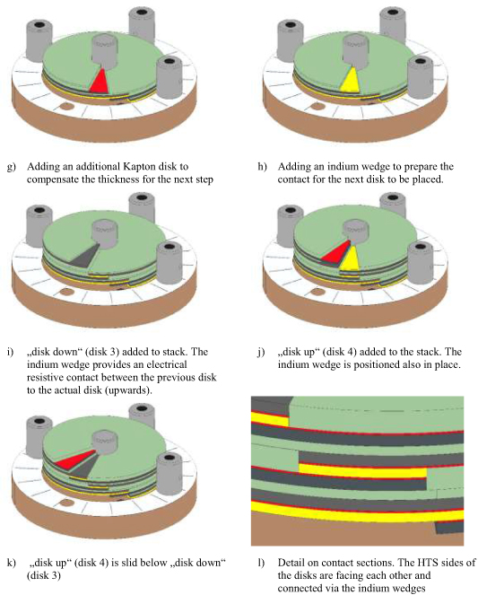
Figure 1. (a)–(f) and (g)–(l) Components and assembly of a circular DUDA stack. Red: HTS; grey: substrate; green: Kapton insulation (different thicknesses to ensure smooth transitions from one section to an other); yellow: indium sections. The final top electrode was prepared very similar to (c) and (d) after placing disk 42.
Download figure:
Standard image High-resolution imageThe commercial HTS tapes used for the DUDA assemblies are described in table 1.
Table 1. HTS tapes and basic properties. Critical current is given for 77 K and self-field.
| DUDA stack | Circular | Rectangular | |
|---|---|---|---|
| Supplier | Deutsche nanoschicht (DNS) | Super-power | SuperOx |
| Deposition | Chemical route | PLD | MOCVD |
| Width (mm) | 40 | 12 | 12 |
| Substrate (µm) | 60 | 60 | 50 |
| Cap layer | Ag | Ag | Ag |
| Stabilizer | None | Cu, 20 µm | None |
| Critical current per width a (A mm−1) | 24–30 | 35–50 | 27 |
| Central bore (mm) | 8 | na | na |
| Length (mm) | na | 150 | 150 |
| Gap length (mm) | na | 85 | 85 |
| Gap width (mm) | na | 4 | 4 |
| Intersheet contacts | Pressed indium | Soft soldered | Soft soldered |
| Critical current (unstructured, average) (A) | na | 230 | 130 |
| Maintained critical current after structuring (before slitting) | na | 64% | 45% |
2.2. Preparation of a circular assembly
To start with a very easy experimental setup, we used 2G-HTS tape by DNS. These tapes were not of highest electrical performance, but simply available in the largest width for first experiments. The DNS-tapes only had a silver cap-layer on top of the HTS-layer (no copper stabilization), a width  and a range of critical current per width of 24–30 A mm−1 w. These samples were structured using a laser into 42 identical slit circular disks. For each disk, the silver cap-layer was covered with Kapton—except for sectors reserved for the contacts (figure 1(a)). Additional Kapton was attached to the substrate of the disk-down elements (figure 1(b)). The primary purpose of the Kapton was to compensate thickness differences in the stacking process; the electrical insulation was of secondary interest. The bottom electrode was covered with an indium disk to provide a good initial contact to the first disk-down element (figures 1(c) and (d)). The 2nd element of disk-up type was place on top and then turned to slide below the contact sector of the 1st element (figures 1(e) and (f)). To provide a smooth base for the next disk-down element, an additional disk of Kapton was placed on top of the assembly and a sector of indium was added on the uncovered silver cap-layer as part of the next contact (figures 1(g) and (h)). The next disk-down element was simply placed on top without the need to turn (figures 1(i)). An indium sector was added to the next disk-up element, which was added and turned to adjust the contact sectors on top of each other (figures 1(j) and (k)). According to this process, in total 42 elements were assembled and then the final top electrode (following an indium disk) was added. The central support part made of FRP for positioning a Hall probe was attached later. To ensure sufficient electrical conductivity across the resistive contacts, pressure was applied over all by clamping the assembly with bolts and FRP sockets (to keep the pressure even when cooling down). The completed assembly was connected with current leads and voltage taps. The voltage taps were placed on the copper plates; as a trial to apply pressure contacts to the disks by through-holes failed. Figure 2 shows a picture of the assembly with a cm-scale.
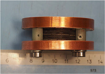
Figure 2. Photograph of the circular DUDA-assembly (inner/outer diameter of 42 disks 8 mm/38 mm; pure stack height 11.2 mm).
Download figure:
Standard image High-resolution imageIn short, the assembly provides a stack of slit, insulated (Kapton), slightly non-planar (to achieve the required steps in the axial direction) disks resistively connected in series (contact sectors with indium).
2.3. Preparation of a rectangular assembly
Rectangular assemblies of modules based on the DUDA concept might be of interest in several configurations.
Figure 3 introduces the general architecture and defines some variables of the central gap. To start with a very easy experimental setup, we used 2G-HTS tapes by SuperPower and SuperOx (see table 1). In total, five of these sheets were stacked following the DUDA-approach (figure 3). In contrast to the circular DUDA, the tapes by SuperOx used for the rectangular assembly were electroplated with 20 µm layer copper. Figure 4 shows the assembly prepared for measurements in liquid nitrogen.

Figure 3. Exploded view of rectangular DUDA with gap of width  and length
  . Red: HTS layers, grey: substrate, yellow: intermediate Kapton layer.
Download figure:
Standard image High-resolution image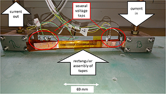
Figure 4. DUDA assembly (see figure 3) out of five tapes mounted on a sample holder for electric measurements in liquid nitrogen.
Download figure:
Standard image High-resolution image3. Results
3.1. Measurements on circular assembly
The circular DUDA assembly (see section 2.2) was immersed into an open dewar filled with liquid nitrogen. The assembly was characterized by transient recording of voltage–current (V–I) and Hall-probe voltage while increasing the current stepwise from measurement to measurement and waiting for stationary conditions (the data corresponding to I = 0 → 10 A, I = 0 → 15 A and to I = 17.6 → 17.8 A is presented in figures 5–7, respectively). The rising ramp was limited by the time constant of the DUDA assembly (discussed in section 4.1); the voltage limit of the current supply (20 V) was clearly above the sample voltage. The recording time was in the 10 s.
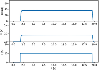
Figure 5. Transient recordings for sample current  = 0 → 10 A, voltage
  and measured magnetic field
  vs time
  .
.
Download figure:
Standard image High-resolution image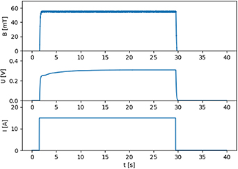
Figure 6. Transient recordings for sample current  = 0 → 15 A, voltage
  and measured magnetic field
  vs time
  .
.
Download figure:
Standard image High-resolution image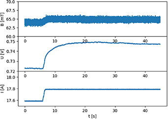
Figure 7. Transient recordings for sample current I = 17.0 → 17.8 A, voltage  and measured magnetic field
  vs time
  .
.
Download figure:
Standard image High-resolution imageCombining the individual measurements into a voltage–current dataset produced the curve in figure 8. From the resistive part in that curve, a resistance of 18.8 mΩ was estimated for the whole setup. The maximum current of 17.8 A corresponded to a calculated axial magnetic central field of  ; a uniform current density throughout the sheets was assumed for the calculation (given that the Hall probe is suitable for a maximum field of 5 T, this is a reasonable alignment at these field levels along with the simple assumption of uniform current density). Following that, to avoid heat production/temperature rise by slow current ramps, pulsed short time measurements (indices 18 and 19 in figure 8) were carried out for sample currents up to I = 150 A (producing ≈0.34 T and ≈400 W of ohmic heat) without a permanent degradation. This is underpinned by the measurement with index 20 reproducing the quasi-stationary U–I characteristic, but a detailed discussion of all transient experiments and effects is beyond the scope of this work.

Figure 8. Electric measurement of circular DUDA-assembly immersed in liquid nitrogen (quasi stationary for  A; pulsed for
  A). The voltage U was measured including the current contacts and the copper disks. The insert shows the low-current region in more detail. The indices near the data points indicate the sequence of measurements.
Download figure:
Standard image High-resolution image3.2. Measurement on rectangular assembly
The electric measurements in liquid nitrogen on the rectangular assembly yielded an overall electric resistance of 465 nΩ and 10 µΩ, and critical currents of 29 A and 90 A for assemblies of wires by SuperPower and SuperOx, respectively. When removing one third of width of the tape, one would expect a remaining critical current of 2/3 of the uncut one. As this is not the case for the SuperPower tape used (see table 1), the weak performance of this assembly might result from critical current variations along the width of the tape (i.e. removing the best performing middle part will lead to a higher reduction of critical current). The SuperOx tape used seemed to be quite homogeneous over the width following the same argument.
3.3. Electromagnetic characteristic of rectangular assemblies (simulation only)
Rectangular assemblies based on the DUDA concept are limited by the available 2G-HTS components. For an initial evaluation of if and how such rectangular DUDA may be of benefit and a subject for further experimental work, we assume  . Let
. Let  represent the critical current per mm-width at a temperature of 30 K and an external magnetic field of 3 T, which is in a typical range for an rotating machine. Furthermore, let
  be the number of individual 2G-HTS plates adding-up to the height
  . Given these values, we calculated the magnetic field profile (see figure 9).

Figure 9. Magnetic field profile simulation (overall magnitude of magnetic field) produced by a rectangular DUDA assembly (having a square cross section of 16 mm2, shown in the central plane of symmetry).
Download figure:
Standard image High-resolution imageHaving chosen a DUDA assembly of square cross sections with a higher p in the xz-plane (so  ), several of these assemblies may be arranged to create a Halbach-array (see figure 10)—very similar to the arrangements by conventional rare-earth based permanent magnets. For the same parameters and combining five DUDA assemblies, the magnetic field on the 'top' side of the arrangement is increased and on the 'bottom' side decreased—see figures 10 and 11.
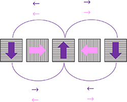
Figure 10. Sketch of Halbach-array based on five rectangular DUDA assemblies of square cross section. The hatches represent the HTS tapes and the arrows indicate the magnetic flux. In the top half space, the magnetic fields amplify, in the bottom half space, the magnetic fields attenuate each other.
Download figure:
Standard image High-resolution image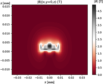
Figure 11. Magnetic field profile simulation (overall magnitude of magnetic field) of a Halbach-array out of rectangular DUDA assemblies (having a square cross section of 16 mm2), shown in the central xz-plane.
Download figure:
Standard image High-resolution image
4. Discussion
4.1. Discussion of circular assemblies
Stacks following the DUDA concept are quite different from the conventional Bitter approach. In Bitter magnets, the complete current path is normal conducting and the resistivity of the contact areas might be comparable to that along the current path within the plates. The intra-plate resistivity yields a current profile  , which favours the largest currents near to the bore. The response behaviour of a Bitter magnet is determined mainly by the inductance and resistivity of the magnet.
In DUDA stacks, the contact resistances in between the disks sum up to the overall resistance, while at the same time producing local heat and raising the local temperature. The critical current of a superconducting disk is—especially at elevated temperatures—strongly depending on the local magnetic field and temperature, e.g.  . In contrast to Bitter magnets a DUDA stack shows some redistribution of current vs radius due to (a) increased temperature (more serious for small radii caused by the smaller contact area) and (b) higher magnetic field at small radii. An initial homogeneous current profile will re-distribute to a current profile with the maximum current at larger radii. The time scale of this redistribution is depending on contact resistances, heat removal, overall current and pinning properties of the HTS. This can be partly observed in the measurements: at low currents (e.g. 10 A), the current in the assembly follows the ramp quite simultaneously and there is no delay in the voltage built-up (figure 5). For higher currents, the voltage over the assembly shows a delay (figure 6). At currents near to the stable limit, not only the voltage, but the built-up of the magnetic field is also delayed (figure 7). More time dependent behaviour could be observed at higher current pulses (e.g. 150 A), but this is beyond the scope of a proof-of-principle discussion. In summary, when evaluating this simple DUDA, one has to consider that (a) the resistive contacts from disk to disk are not optimized at all, (b) the resistance of the contacts decreases with increasing radius due to increasing contact area, (c) there will be a heating from the contacts between the disks and (d) there will be a redistribution of current. To reduce these effects, one should optimize the contacts in shape, size and resistivity. The pulsed measurements indicate that the current performance of the circular DUDA is mostly limited by heating/ temperature increase and not by
  This is supported by the observation on the rectangular DUDAs with SuperOx-tape showing the full expected current performance.
Operating the assembly at lower temperatures (e.g. 30 K, 20 K or 4 K) will also reduce the redistribution effects, because contact resistivities and the  dependence are reduced. When using state-of-the art 2G-HTS tapes with a higher performance (e.g. >60 A mm−1 w instead of ⩽30 A mm−1 w at temperatures of liquid nitrogen, or >300 A mm−1 w at temperatures of 30 K) the expected magnetic field will be improved by at least a factor of 2–10 in the same geometry.
4.2. Relevance for compact magnets
Having 2G-HTS sheets available in appropriate geometries and operating the assemblies at lower temperatures, magnets of 6–10 T are envisaged in the near future, when larger sheet numbers and dimensions are available. Presently KIT ITEP is erecting a pulsed-laser-deposition for the preparation of research tapes and sheets. There is the drawback of having contact resistances in between the sheets (which might be led out and cooled separately with higher power) and in general the magnetic field is mostly directed along the c-axis which leads to a reduced critical current—but this limits the operating current in nearly all windings. However, there are several advantages to counterbalance that:
- Homogeneous material in the radial direction. In tape-wound coils, due to the layered structure, there is always a sequence of substrate, HTS, copper and potentially other materials (e.g. silver, resin, insulation) leading to (shear) forces with increasing winding height and to potential degradation/delamination in the winding.
- The assembly is made up by several limited size modules, which might be tested in advance and should not ruin the material:scrap ratio of a supplier, which leads, in the long term, to a low cost situation.
- Heat removal (for nominal operation or considering quenches) from the inner radius to the outer radius is facilitated by in-plane heat conduction in the sheets, and thus expected to be superior to the heat removal in wound pancake coils.
- Lorentz-force/hoop stress is handled within the individual sheets not necessarily producing shear stress.
When considering miniaturized magnets, the (rectangular) DUDA concept enables the building of high-field benchtop magnets suitable for producing some Tesla—especially when arranging rectangular DUDA coils in a Halbach-array to strengthen the magnetic field in one half-space.
4.3. Relevance for energy technology
Rotating electric machines have been built using HTS in the field winding only (partially superconducting machines) [12] and in a very few cases in the armature winding as well (fully superconducting machines) [13, 14]. These machines benefit from the higher air-gap field by the HTS field winding (typically producing a field of ≈3 T) and the higher current density in the stator winding [15]. As long as the windings are based on wound-wire coils, there is a limit to miniaturization (resulting from the minimum bending radius) and thus in the possible number of poles and slots in a given cross section. Using the rectangular DUDA concept, these coils can be miniaturized to a width as low as e.g. 4 mm and easily extended to a length of 5000 mm—the latter one will reduce the impact of contact resistance on the overall performance considerably. Furthermore, placing the contacts at only one end of a rectangular DUDA allows easy heat removal at one side of the winding package. Such coils will allow extremely high numbers of poles and slots in rotors and stators.
Furthermore, deciding to use a Halbach-configuration of DUDA coils in the rotor (as is frequently the case with conventional rare-earth based permanent magnets) will lead to a higher air-gap magnetic field, a reduced rotor forging magnetic field and the reduction of harmonics. These approaches will be of special interest to motors and generators in wind power and in vehicles (e.g. electric aircrafts, ships and trucks).
4.4. Relevance for high-energy physics
The DUDA approach opens up pathways to miniaturize magnets by eliminating the restriction of minimum bending radii of wires. This will allow building of wiggler and undulator magnets with extremely small spatial wavelengths while providing strong magnetic fields [16, 17]. Given that the 2G-HTS sheets are available in appropriate sizes it will be possible to prepare strong dipole magnets for accelerators very similar to the 'feather' dipole magnet [18], but with fewer components. The DUDA concept is opening up new designs and topologies for accelerator magnets.
4.5. Further work
To further elaborate on the DUDA concept, the following challenges might be addressed:
- (a)Improving inter-sheet contacts.
- (b)Characterizing a DUDA stack at low temperatures and in background fields.
- (c)Studying the potential of rectangular DUDA stacks for the windings in rotors and in stators of rotating machines.
- (d)Experimentally accessing the potential and characteristics of a Halbach-array based on DUDA stacks (at temperatures of 20 K–30 K for rotating machines and for compact benchtop magnets).
- (e)Building high-field short-wavelength undulators/wigglers following the DUDA concept.
- (f)Assembling a deposition device for wide and homogeneous 2G-HTS sheets/tapes.
- (g)Using wide sheets to explore DUDA-based dipole magnets.
We plan to address the challenges 1, 2, 3 and 6 in the short and mid-term.
5. Conclusions
We introduced a new coil configuration by stacking 2G-HTS sheet in a DUDA concept. First designs, preparations and experiments on small circular assemblies (≈40 mT in stationary, ≈340 mT in pulsed operation in a 8 mm bore when using 2G-HTS of moderate critical currents of ⩽30 A mm−1 w and only moderate performance of critical current in field) and rectangular assemblies immersed in liquid nitrogen proved the feasibility of the concept.
Improvements are needed in the design, location and resistivity of joints in between the sheets, especially for the circular DUDA.
Operating DUDA assemblies at lower temperatures will offer considerably increased currents and magnetic fields. Magnetic fields comparable to experiments with trapped fields in stacks of 2G-HTS [6] seem to be achievable.
The DUDA concept offers new chances in compact magnets, energy technology (rotating machines) and accelerator technologies.
Acknowledgments
The contribution of the colleagues Matthias Eisele, Reinhard Ernst, Frank Gretschmann and Patrick Schäfer is strongly appreciated.
Data availability statement
All data that support the findings of this study are included within the article (and any supplementary files).