
Abstract
The production of large (RE)Ba–Cu–O single grains ((RE)BCO), where RE = Y, Gd or Sm, of complex geometries is presently limited by the intrinsic slowness of the grain growth process. Additionally, the shapes achievable using established melt processing are constrained by the small number of post-processing techniques available. These materials are brittle and hard, which makes machining a difficult task and largely eliminates the possibility of producing highly intricate shapes. An alternative to this slow and inflexible growth process would be to join many small single grains to form one large composite grain, connected by high-performance superconducting joints. A reliable joining technique would also overcome the need for the careful and time-consuming post-growth machining processes. In this work we report on the use of single grain YBCO–Ag as an interface medium to achieve superconducting joints between (RE)BCO bulks. This joining technique is relatively quick and does not require tight process parameter control as there is no need to re-grow the interface joining material. We report on six joints produced from samples cut and joined in a variety of orientations. In addition, a joint was produced using bulk YBCO from two independent single grains. The trapped field properties of the resulting joined sample were measured and the microstructure at the joint was examined. We show that this simple but effective joining technique makes it possible to produce multiple composite grains with comparable superconducting properties to those of a single grain of the same size.
Export citation and abstract BibTeX RIS

Original content from this work may be used under the terms of the Creative Commons Attribution 4.0 license. Any further distribution of this work must maintain attribution to the author(s) and the title of the work, journal citation and DOI.
1. Introduction
Large single grains of RE–Ba–Cu–O ((RE)BCO), where RE is a rare earth element or Y) are formed from the peritectic reaction between (RE)Ba2Cu3O7 (RE-123) and an excess of (RE)2BaCuO5 (RE-211). These high temperature superconducting bulks have the ability to trap magnetic fields that are significantly larger than those generated by conventional permanent magnets [1]. Potential applications include levitation devices, such as Maglev trains, energy storage flywheels and rotating machines (as both motors and generators) [2–5].
The single grain nature of bulk (RE)BCO single grains is particularly important as grain boundaries within the sample microstructure significantly reduce electrical connectivity and current flow. In turn the trapped field is determined essentially by the extent and magnitude of the current loop that can be established [6–11]. Two techniques are widely used for the fabrication of grain-boundary-free (RE)BCO: top seeded melt growth (TSMG) and infiltration growth (IG) [9, 12]. Both techniques rely on controlled undercooling and nucleation from a discrete seed, and invariably involve extended periods of slow cooling as part of the fabrication process. As a result, sample production is an intrinsically slow process, typically taking over 4 d to produce a 25 mm diameter YBCO single grain by TSMG. This, coupled with the observation that superconducting properties usually decrease with increasing sample size, alongside difficulties with cracking and porosity, mean that most bulk single grain superconductors produced are <30 mm in diameter. Samples larger than 60 mm are rare [13, 14].
One potential approach to growing a single, large bulk superconductor is to join many smaller single grains to form one large composite grain with small grain misorientation angles. This would also address the need for complex geometries required for many applications, including NMR, flywheels and motors [4]. A reliable joining process would also overcome the need for the careful and lengthy machining processes currently used for shaping as-grown bulk samples. The brittle nature and high hardness of these materials makes machining difficult and virtually eliminates the possibility of producing highly intricate shapes of these technologically important samples.
Bulk superconductors fabricated from joined individual grains must fulfil a number of criteria in order to be suitable for practical applications. Most critically, the interfaces should exhibit Jc values comparable to that of the single grain material. To achieve this, the joints need to approximate to a low angle grain boundary. They should therefore be free of defects such as trapped liquid phases, pores and voids, and variations in stoichiometry. These factors not only improve the superconducting properties but also enhance the mechanical properties of bulk single grains. The joint must have sufficient mechanical strength to withstand the Lorentz forces experienced during magnetisation and use.
Four main categories of techniques have previously been applied to join single grain bulk YBCO samples. Early investigations used solid-state diffusion. In its simplest form this technique relies on achieving perfect contact between two interfaces to be joined without the use of additional material. The material is heated without melting and a joint is formed. This technique requires carefully polished pieces of bulk superconductor to be held together at a high temperature for an extended period, while a large load is applied to the arrangement. This typically requires temperatures over 900 °C for a minimum of 12 h during which at least 0.1 MPa of pressure must be maintained across the joint [15–17]. Despite the inherent complexities and challenges associated with this technique, a number of studies have successfully produced mechanically robust joints using solid-state diffusion. However, in all cases the superconducting properties of the joined samples were notably inferior to those of as-grown single grains [15–18].
A 2nd category of technique is based on infiltration joining. In this technique the gap between the two bulk superconductors to be joined is filled with RE-211 powder. An additional powder pellet provides a liquid phase which, on melting, infiltrates the powder in the gap. This uses the same principle as the IG technique for growing large single grains. A variety of ytterbium, yttrium and erbium-based powder compositions have been trialled for this purpose [19]. The RE-211 powder has a lower decomposition temperature than YBCO, so the bulk superconductor sections both remain solid throughout the joining process and facilitate epitaxial nucleation. Mechanically robust joints with a highly aligned structure and low residual porosity have been produced using this technique. However to-date no superconducting properties have been reported for this type of joint [19, 20].
A 3rd, more widely investigated, set of techniques uses a weld material between the YBCO bulk single grain sections to be joined. The weld material necessarily has a lower peritectic temperature than YBCO, so is typically thulium [21–26], ytterbium [27–30] or erbium-based [30–32] (RE)BCO or YBCO–Ag [33–37]. On heating, the weld material melts while the majority of the single grain remains solid. The original grain structure is hence retained, and acts to self-seed the weld material. This technique necessarily requires an extensive slow cooling period to promote grain growth within the weld material.
The weld material used can take a variety of forms including powder, a suspension painted onto the surface or pre-sintered green powder compacts. These joints tend to exhibit inferior superconducting properties, due to the differences of the fabrication process compared to those of single grain YBCO. This is usually attributed to the accumulation of impurities at the edge of the weld material [21]. The superconducting properties of the joint were improved when the number of pores and voids were reduced by the application of external pressure. The joint quality was also improved by enabling a sharp, planar growth front to propagate through the weld material. This was achieved by providing a well-polished joint surface and reducing the size of the RE-211 inclusions at the growth front [29].
The quality of a YBCO–Ag welded sample was later compared to the cross-section in the region between two seeds in a multi-seeded bar. The welded sample appeared to have a better quality joint when compared with the interface between the two seeds, both in terms of the superconducting properties and the microstructure [35]. The use of YBCO–Ag weld material before and after ball milling was investigated subsequently by Iida et al who produced a joint with good alignment between the bulk and the weld material. This joint produced a promising result of 0.15 T maximum trapped field in a section approximately 10 mm square [37]. A similar process was used more recently in work by Wei et al but this incorporated a more limited slow cooling period. This reduced the processing time significantly but did not enable a higher maximum trapped field to be achieved in the joined sample.
The final subset of techniques use a thin layer of a material, such as silver foil, to reduce the peritectic temperature of the material in close proximity to the joint. The material at the interface subsequently melts while the majority of the YBCO remains solid. An advantage of this method is that the heating profile does not need to be as tightly controlled as in the welding technique, as there is no relatively thick layer of weld material that must recrystallise. Analysis by Iliescu et al suggested that the penetration depth of the silver controlled the thickness of YBCO that melted [38, 39]. The resulting joint was of high quality and, encouragingly, produced a trapped field profile with a single peak [39]. This technique yielded a value of Jc of 1.35 × 10⁴ A cm−2 across the joint. This is comparable to the value of Jc observed in a relatively poor-quality single-grain YBCO bulk superconductor by today's standards.
In this paper we describe a new approach to the jointing of single grain bulk YBCO superconductors that combines elements from the welding approach with the use of silver to reduce the local peritectic temperature. In this way we demonstrate a method to allow bulk superconductors to be joined at relatively low temperatures and without the need for slow cooling thermal ramps.
2. Method
2.1. Sample growth
Seven samples of YBCO were grown by liquid-phase-enriched TSMG (LR TSMG) [40]. Six samples were pressed uniaxially from 99.9% purity powders of Y-123:Y-211:CeO2 in the mass ratio 150:50:1 in a 25 mm diameter cylindrical die. One was pressed uniaxially in a 30 mm diameter cylindrical die. In addition, three samples of YBCO–Ag of 26 mm diameter were grown by LR TSMG [41]. The precursor powder was mixed from 99.9% purity powders of Y-123:Y-211:CeO2:Ag2O in the mass ratio 150:50:1:20. In both cases the LR powder was mixed from Yb2O3:Ba3Cu5O8:BaO2 in the mass ratio 5.0:5.6:1.0. Prior to the growth process it was calcined for 5 h at 850 °C.
After melt processing, all seven YBCO samples were annealed in oxygen for a minimum of 8 d at 450 °C. This transformed the Y-123 tetragonal structure to the superconducting orthorhombic structure. The magnetic field trapping ability of the parent YBCO single grain samples could then be measured prior to joining.
2.2. Trapped field measurement
The top and bottom faces of six of the YBCO samples were polished flat and parallel using 180 grit silicon carbide paper. The maximum trapped field at the top and bottom surface was measured initially using a hand-held Hall probe positioned 0.5 mm from the sample surface. Subsequently, the trapped field profile across both the top and bottom surface of each single grain was measured using a rotating array of 19 Hall probes positioned approximately 1.5 mm above the surface of each sample. The samples had been field cooled at 77 K in an applied magnetic field of 1.4 T prior to trapped field measurement. The temperature of each sample was maintained at 77 K for the duration of the measurements.
2.3. Joining technique
Each of the six smaller YBCO samples was cut in half across a diameter; three along the facet line and three mid-facet line. The single, larger YBCO sample was cut mid-facet line, as shown in figure 1. The two rectangular cross-sections produced by cutting were polished progressively using silicon carbide paper and diamond paste.

Figure 1. The cutting direction of the YBCO single grain samples (a) along the facet line and (b) mid-facet line.
Download figure:
Standard image High-resolution imageSlices of thickness between 1.0 mm and 1.5 mm were cut from the YBCO–Ag single grain samples, as illustrated in figure 2. These slices were polished by hand using 2500 grit silicon carbide paper.
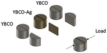
Figure 2. A schematic illustration of the process used to join single grain YBCO bulk superconductors with an intermediate YBCO–Ag joining medium.
Download figure:
Standard image High-resolution imageTwo halves of YBCO were assembled either side of a single slice of YBCO–Ag, with the configuration of the two halves given in table 1, as shown in figure 2. This assembly was supported on stabilised zirconium oxide rods prior to thermal processing. Two small lateral point loads (less than 1 N total load) were applied to assist the contact between the two YBCO half samples and the joining YBCO–Ag slice during the heating process. The assemblies were heated in a box furnace in air at a rate of 100 °C h−1 to 980 °C, held at this temperature for 10 h and then cooled at a rate of 100 °C h−1 to ambient.
Table 1. Joined sample compositions.
| Joined sample | Original samples | Cut orientation | Relative c-axis orientation |
|---|---|---|---|
| J1 | Y1 | Mid-facet line | Same |
| J2 | Y2 | Mid-facet line | Same |
| J3 | Y3 | Along facet line | Same |
| J4 | Y4 | Along facet line | Same |
| J5 | Y5 | Along facet line | Opposite |
| J6 | Y6 and Y7 | Mid-facet line | Opposite |
Finally, the joined samples were annealed in oxygen for a minimum of 8 d at 450 °C in order to transform the Y-123 tetragonal structure to the superconducting orthorhombic phase. The trapped field at the top and bottom of the joined samples was measured after the oxygenation process, as described above.
2.4. Microstructural analysis
Three joined samples, J2, J3 and J6, were cut in half along a diameter to expose a central rectangular cross-section. The orientation of the cut was perpendicular to the joint in each case. The central cross-section was polished using silicon carbide paper of progressively finer grit followed by diamond paste. Visible brightfield images were taken throughout the cross-section at 50× magnification to enable a detailed picture to be constructed from multiple images. In addition, images were taken at 200× magnification within 1 mm of the joint to observe the silver and Y-211 distribution in the vicinity of the joint alongside any voids.
2.5. Compositional analysis
A number of points across the cross-section of J3 and J6 were imaged at 150× and 200× magnification using a scanning electron microscope (SEM). Images were taken at 1 mm intervals at the centre of the c-axis in the a/b-axis direction, moving outwards along the a/b-axis from the centre of the cross-section. In addition, the central region of sample J6 was imaged 2 mm below the top surface of the sample along the c-axis. An area of approximately 160 μm by 100 μm at each of these locations was analysed using energy-dispersive x-ray analysis (EDAX) to observe the variation in the distribution of silver in the sample microstructure. In addition, sample J3 was imaged and analysed by EDAX at a magnification of 100× to visually observe the distribution of silver across the joint interface.
3. Results and discussion
3.1. Sample growth and joining
Each of the YBCO and YBCO–Ag samples were successfully grown as single grains. The measured samples each exhibited a single peak in their trapped field profiles, characteristic of a single grain sample. The maximum fields trapped in each of the single grains are given in table 2.
Table 2. Maximum trapped field of the original bulk single grains compared to the maximum trapped field of joined samples.
| Un-cut YBCO | Top (T) | Base (T) | Joined sample | Top (T) | Base (T) |
|---|---|---|---|---|---|
| Y1 | - | - | J1 | 0.26 | 0.18 |
| Y2 | 0.56 | 0.57 | J2 | 0.20 | 0.18 |
| Y3 | 0.52 | 0.39 | J3 | 0.36 | 0.39 |
| Y4 | 0.54 | 0.38 | J4 | 0.40 | 0.20 |
| Y5 | 0.36 | 0.27 | J5 | 0.31 | 0.27 |
| Y6 | 0.48 | 0.35 | J6 (Y6 and Y7) | 0.21 | 0.20 |
| Y7 | 0.52 | 0.42 | — | — | — |
The two halves of the samples were cut and joined in a variety of orientations. In one case halves from two independent YBCO single grains were used. Each of the joints produced using this technique was mechanically robust to manual handling and could support self-weight. In addition, the top surface of each YBCO bulk half-sample retained its single grain appearance. In no case were there obvious signs of large-scale melting of the YBCO. Photographs of the jointed samples are shown in figure 3.

Figure 3. Photographs of the joined samples; (a)–(f) correspond in order to samples J1–J6.
Download figure:
Standard image High-resolution imageThe maximum trapped field achieved in the joined samples is comparable to that achieved in the parent single grain samples prior to cutting. The maximum trapped field achieved in each joined sample is given in table 2 alongside the maximum trapped field achieved in the original YBCO samples. This is supported by the trapped field profiles of the original sample Y3 and joined sample J3 shown in figure 4. Together these show that the material at the interface of the joint is largely continuous and able to support a flow of critical current similar to that observed in the parent YBCO single grain.
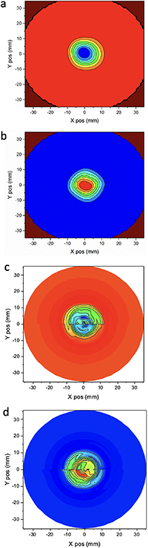
Figure 4. Trapped field profiles of joined samples (a) Y3 top, (b) Y3 base, (c) J3 top, and (d) J3 base.
Download figure:
Standard image High-resolution imageSample J1 was joined first as a proof of concept and hence the trapped field of the original single grain was not measured. However, the maximum trapped field and the trapped field profile of this joined sample is promising, exhibiting approximately half of the trapped field expected for a fully grown, good quality single grain of this size.
Sample J2 was identical to sample J1 in terms of preparation except the single grain of the former was 4 mm larger in diameter. Sample J2 exhibited approximately half the maximum trapped field that the single grain achieved prior to cutting.
Sample J3 was cut along the facet line, unlike samples J1 and J2, which were cut mid-way between two adjacent facet lines. It is widely accepted that, due to the growth process and the direction thereof, there is a change in stoichiometry and porosity in close proximity to the facet lines. There are typically fewer pores and fewer Y-211 agglomerates near the facet lines. This suggests that joining along the facet line may be less disruptive to the continuity of the stoichiometry of the single grain than joining between the facet lines. This sample achieved a maximum trapped field at its base identical to that of the single grain sample. The maximum trapped field at the top surface was however 0.16 T lower than the 0.52 T achieved on the top surface of the single grain prior to cutting.
Sample J4 was prepared in the same way as sample J3, and with the same dimensions. This sample exhibited a comparable maximum trapped field to the original single grain, reduced by only 0.1 T at the top and bottom surfaces.
Sample J5 extended this technique to joining two halves from the same YBCO bulk single grain but with the c-axes pointing in opposite directions. This produced promising results, with the top and bottom of the joined sample achieving the same maximum trapped field as the original bulk sample to within 0.05 T. Significantly, this result suggests that a superconducting joint can be achieved even if the pieces joined are not oriented in the same direction.
In order to further evaluate the wider applicability of this technique, two halves from independently grown samples were cut and joined mid-way between the facet lines with the c-axis aligned in opposite directions to form sample J6. This joint configuration was chosen to provide a lower bound for the level of maximum trapped field achievable using this technique, as joints had been shown to have a lower trapped field when the original samples were cut and joined in this orientation. This sample showed a promising maximum trapped field value at both the top and bottom surfaces, which was approximately half of that achieved in the original samples prior to cutting. The base of the joined samples exhibited a distinctive single peak, although a slight 2nd pronounced peak was present at the top surface of the joined sample. This suggests that the interface between the two halves was not continuous in the region close to the top of the joined single grain.
3.2. Microstructure
Three of the samples, J2, J3 and J6, were examined using an optical microscope at magnifications of 50× and at 200× in the vicinity of the joint. These samples were chosen as they included a combination of the different joining orientations.
It should be noted that these samples have experienced two cutting processes and two oxygenation processes. Therefore, there is likely more cracking than would be observed in a joined sample once the joining technique has been fully optimised. Once the joining technique has been optimised there will be no need to oxygenate the parent samples before joining and no requirement to observe the microstructure.
One half of the joint interface between the YBCO single grain and YBCO–Ag joint material in sample J2 is not continuous, as shown in figure 5(a). The observed gap was unlikely to have been present when the trapped field was measured, prior to cutting, since the trapped field profile did not exhibit two distinct peaks. In addition, silver has been able to diffuse into the YBCO single grain to the left of the crack position, which suggests that there was direct contact between the interfaces during heating. It is hence likely that the joint between the interfaces was continuous when the trapped field profile was measured but that the joint was not sufficiently robust to survive the cutting and polishing process prior to inspection. The interface between the YBCO–Ag and the YBCO bulk is continuous on the right-hand side of the joint. The limited robustness and continuity at the left-most interface is likely to explain why this joined sample only trapped approximately half of the maximum trapped field of the parent single grain. The likely reason for this reduced integrity is that the force applied during the joining process is low and there is limited control of where and in which direction this is applied. This could be improved significantly by using a bespoke clamp to enable the magnitude and positioning of the force to be controlled more carefully.
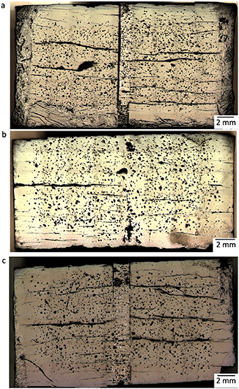
Figure 5. Microscope images at 50× magnification of (a) J2, (b) J3, and (c) J6.
Download figure:
Standard image High-resolution imageThe microstructure in the vicinity of the joint in sample J3 exhibits a much more continuous interface between the two YBCO single grain halves and the YBCO–Ag jointing layer. This is shown in figure 5(b) and at higher magnification in figure 6(b). With the exception of a few small voids and the obvious signs of silver (visible in the figure in yellow), it is difficult to distinguish where the interfaces occur in this sample. This suggests that a good joint was formed. The continuity observed in the microscope images is as expected, given the trapped field profile and higher maximum trapped field achieved in this sample.
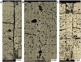
Figure 6. Optical microscope images in the vicinity of the joint at 200× magnification of (a) J2, (b) J3, and (c) J6.
Download figure:
Standard image High-resolution imageThe microstructure in the vicinity of the joint in sample J6 is shown in figure 5(c). This reveals a more continuous interface than in sample J2, but a less continuous set of interfaces than in sample J3. There are regions where the interface appears to be continuous, although there are also regions where there are voids present. It is again likely that these regions are due to the low magnitude of the forces applied during joining and the limited control of the location and direction of these forces. In addition, the flatness of the surfaces could be improved to provide a greater area of conformal contact at the interfaces. These partially continuous interfaces account for the reduction in maximum trapped field compared to the uncut bulk single grain.
3.3. Composition analysis
The distribution of Y, Ba, Cu and Ag at the centre of the c-axis reported from the EDAX analysis is shown in figure 7 for samples J3 and J6, these have been cut along the facet line and mid way between the facet line, respectively. The direction of movement is from the centre of the cross-section radially outwards along the a/b-axis. In both samples the silver has diffused a short distance; the 1 mm location is just beyond the interface between the YBCO bulk and YBCO–Ag jointing layer. This suggests that silver has not diffused further than 1 mm to 2 mm from the centre of the sample in both J3 and J6. This further indicates that the only part of the YBCO sample where the silver lowered of the peritectic temperature was within 1 mm of the interface between the YBCO–Ag and the cut YBCO single grains. This behaviour was also observed at the top of the sample in J6, as shown in figure 8. The centre of the sample is labelled as the 0 mm location in this figure.
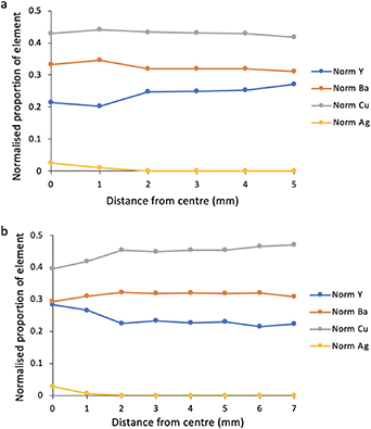
Figure 7. Distribution of Y, Ba, Cu and Ag normalised with respect to the total Y, Ba, Cu and Ag in a radial direction from the centre of the sample for (a) J3, and (b) J6.
Download figure:
Standard image High-resolution image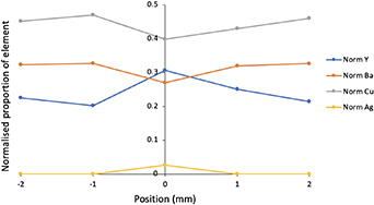
Figure 8. Distribution of Y, Ba, Cu and Ag normalised with respect to the total Y, Ba, Cu and Ag in J6, taken 2 mm from the top of the sample and where location zero is at the centre of the a/b-axis.
Download figure:
Standard image High-resolution imageThis distribution of silver can also be mapped using EDAX, and figure 9(b) shows the false-colour image generated for silver in sample J3 (silver is highlighted in orange). This image can be compared to the SEM image taken at the centre of the cross-section of J3 at the same magnification, shown in figure 9(a). It is then apparent that the majority of the silver can only be distinguished clearly within and immediately around the central YBCO–Ag joining belt.

Figure 9. (a) SEM image of the centre of the cross section of J3; the yellow lines indicate the edge of the YBCO–Ag band, and (b) a false-colour image produced in EDAX to locate silver in the microstructure (orange).
Download figure:
Standard image High-resolution image
Taken together, these results show that joints between two halves of YBCO bulk single grains can be produced that support a trapped field comparable to that of the parent single grain samples. These joints can be produced simply and relatively quickly, and only require limited process control. This is possible because the localised diffusion of silver from a singled-grained piece of bulk superconductor enables a localised reduction in the peritectic temperature. Only a limited region at the interface is required to recrystallise during the heating process rather than a relatively thick piece of multi-grained weld material. There is, therefore, no need for a slow-cooling period post-heating. This makes the technique relatively simple, and it requires a low level of process control, which is significant for the commercial development of these technologically important materials.
4. Conclusions
A reliable technique to join bulk, single grain YBCO superconductors has been developed. The joined bulk superconductors exhibit superconducting properties comparable to those of the parent single grain samples. This technique is relatively quick to implement and is conceptually straightforward. It requires limited specialist equipment and low levels of process control due primarily to the use of single grain YBCO–Ag as an intermediate material in the joint. The silver content of the joint diffuses locally at the joining interface to create a localised reduction in the peritectic temperature of the YBCO at the joint. This eliminates the need for large-scale melting and recrystallisation, so a tightly-controlled slow-cooling stage is not necessary during the joining process.
The ability to produce composite (RE)BCO grains through a simple, reliable joining technique provides many exciting opportunities for (RE)BCO bulk superconductors to be used in practical applications where large or intricately shaped samples are required.
Acknowledgments
The authors would like to acknowledge support from the Engineering and Physical Sciences Research Council (EPSRC) Grant EP/T014679/1.
Additional data related to this publication is available at the University of Cambridge data repository [https://doi.org/10.17863/CAM.72011]. All other data accompanying this publication are directly available within the publication.
Data availability statement
The data that support the findings of this study are openly available at the following URL/DOI: https://doi.org/10.17863/CAM.72011.