
Abstract
Fusion energy systems studies (FESS) for next-step devices based on the most promising magnetic configurations indicate that high magnetic fields and high current density for magnet coil systems may reduce device size and lower the cost. High current density and radiation resistant fusion magnets are particularly beneficial for low cost, low aspect ratio compact reactor designs such as Fusion Nuclear Science Facility (FNSF), Fusion Pilot Plant (FPP) of low-aspect ratio spherical tokamak (ST) or compact stellarators. Unlike typical high field magnets for nuclear magnetic resonance (NMR), magnetic resonance imaging (MRI), or high energy physics research applications, neutron irradiation damage to organic insulations in the coil winding pack is a critical issue for next generation fusion reactors where orders of magnitude higher neutron fluence than those in present experimental reactors such as ITER are expected. Moreover, a high coil winding pack current density is needed for high field magnets in low cost, compact radial build next step fusion reactors. The slow current charging time, however, is an issue in fully non-insulated coils. We present the design, construction and testing of subscale Nb3Sn solenoids, up to half the diameter of the central solenoid (CS) for National Spherical Torus Experiment (NSTX), with and without inter-layer insulation for enhancing radiation resistance while improving the winding pack current density and coil performance. The major radius for the NSTX/NSTX-Upgrade (reference for compact ST) is 0.854/0.934 meter, and 4.8 meters for FNSF. The magnetic field for NSTX/NSTX-U at the plasma center is 0.6/1 Tesla and 9 Tesla for FNSF. The inner diameter of the central solenoid coil is 0.2/0.4 meter for NSTX/NSTX-U and 1.2 meters for FNSF. The current charging and discharging behavior of the prototype solenoids was investigated to quantify performance advantages of a simplified coil fabrication without error-prone vacuum pressure impregnation (VPI) for the removal of epoxy organic insulation. Scalability of the no insulation concept for fusion can be addressed via engineered coating for novel insulation on contact resistance or intra-layer no insulations. Radiation resistance and coil winding efficiency were significantly improved in the no insulation coils for next step compact fusion reactors.
Export citation and abstract BibTeX RIS
1. Introduction
The fusion energy sciences advisory committee (FESAC) recently reported that 2 G high-temperature superconductors (HTS) are transformative enabling capabilities for the U.S. to pursue that could promote efficient advances towards fusion energy, building on burning plasma science and technology [1]. The National Academies also released a new report in 2021 on bringing fusion to the U.S. Grid with committee recommendations on the key goals and innovation needed for the U.S. Fusion Pilot Plant (FPP) [2]. At least two different magnetic configurations are under consideration. Tokamaks, with significant time-changing fields and thus coil voltages in central solenoid (CS), poloidal field (PF) and control coils, may require high current cables or novel insulations, while stellarators, where magnetic fields are in steady state and several strategies may be used for making 3D field shaping, can be more suitable for no insulation (NI) coils. Unlike superconducting magnets for high energy physics, nuclear magnetic resonance (NMR), magnetic resonance imaging (MRI) applications, or small bore research magnets, coils in fusion relevant environments and their operating modes are unique and it is more challenging to achieve high central fields in large size bores or large aperture fusion devices such as that in ITER [3], currently under construction in the South of France. The state-of-the-art low temperature superconducting (LTS) magnet technology is being demonstrated by ITER. The first D-shaped toroidal field (TF) coil and the first CS coil module are expected to arrive at Cadarache ITER site for tokamak assembly by the end of this summer. The LTS magnet technology is also adopted by the K-DEMO and E-DEMO for TF and CS coils [4, 5]. Although compact spherical tokamak (ST), such as the low aspect ratio National Spherical Tokamak Experiment (NSTX) and the NSTX-Upgrade built and operated at Princeton University Plasma Physics Laboratory, favored an increased plasma performance including better shaping, confinement and stability limits, it posed significant engineering challenges for the design, construction and assembly due to tight space in the TF in-board radial build [6]. Significant progress has been made in the past few years on the maturity of HTS for high field magnet applications [7–9], including prototyping and testing of HTS cables and fusion relevant model coils at privately funded startup companies such as ST40 reactor at Tokamak Energy [10] and SPARC at Commonwealth Fusion [11].
Qualification of conductor insulation is one of the most challenging but critical issues in the manufacturing of fusion magnets. The conventional coil insulation system includes glass fiber and epoxy resin composite, where the glass fiber provides the mechanical strength needed for winding pack integrity and epoxy resin prevents wire movements and binds coil turns together. The Kapton layers can provide clear slip planes for electrical insulation. The composite insulation is a critical design driver in many situations for coil winding pack structural integrity in high field magnets such as those for ITER. The conventional organic insulation has an order of magnitude lower elastic modulus as compared to a jacketed cable-in-conduit (CIC) conductor. This difference made coils experience a spongy effect, as it creates a winding elastically soft and the sponginess increases the mechanical strain effect, in particular the insulation normal tensile strain when the coil is energized [12, 13]. Conventional insulation composites also reduce the overall winding current density, while it electrically isolates turns in the winding and prevents current bypassing through adjacent turns during quench for coil protection. To integrate magnet design with burning plasma physics in a DEMO or FPP device beyond ITER, the influence of neutron irradiation to organic insulation and epoxy vacuum pressure impregnation shall be addressed. ITER studies indicated that conventional insulation systems degrade at a much lower neutron fluence level than the limit of the superconductor and the copper stabilizer. To this end, a low neutron fluence limit of 1 × 10²² n m−2 in organic insulation has thus become the design driver [14]. For FNSF or FPP operations, orders of magnitude higher neutron fluence than that in ITER are expected [6, 15–17]. The no-insulation (NI) coil concept has been actively investigated since it was introduced over a decade ago. NI HTS coils have been successfully tested in the high field magnet community for various non-fusion applications [18–21]. The slow current charging time [18–20], however, is a potential issue when the NI coil design concept is applied for operating large scale fusion magnets, particularly for the central solenoid where a fast current ramping is needed for plasma startups [22, 23]. Stellarators and other fusion devices such as a field-reverse configuration (FRC) device, however, do not need a fast ramping field to startup plasma and the NI coils can be promising. A method of feedback control on the power supply was proposed as a potential mitigation to significantly reduce the charging delay and steady-state field instability in operating an NI magnet [24]. Partially insulated coil design concept was also studied [25–29] to ensure the transient stability while maintaining a balance for quench protection.
We presented design, construction, and helium testing of in-house built Nb3Sn solenoid prototype coils, up to half the diameter of the NSTX CS coil but with significantly reduced organic insulation in coil winding, to enhance overall current density. The critical current performance during charging, discharging, and a quench event was investigated in a test campaign for better understanding advantages of a simplified NI coil fabrication process, where the coil winding efficiency and radiation resistance were improved. These improvements are beneficial for magnet design of FNSF as well as the low aspect ratio ST or next step compact stellarators [6, 16, 17].
Previous investigation on fusion includes the development of ceramic/organic hybrid insulation [30], where expensive vacuum pressure impregnation (VPI) process is required; other ceramic coating techniques also require extensive modifications of the coil fabrication process [28, 29]. Solder filling was tested recently as non-organic impregnation of HTS NI coils [11, 31]. An intra-layer winding method for no-insulation layer-wound REBCO coil for shortening magnetic field delays but still preserving the self-protection for quench was also proposed [32]. The work presented here is to demonstrate a new non-VPI NI approach in simplifying the coil fabrication for developing radiation-tolerant fusion magnets for compact ST reactors. The subscale prototype NI solenoids were made of ITER Nb3Sn wires; coils were not impregnated but they were built with additional structural reinforcement for enhanced structural integrity. We tested the performance of NI coils made with the simplified fabrication process in order to lower cost and improve the winding pack current density, relevant for the design of a fusion pilot plant.
Magnet coil systems typically have the largest cost of all subsystems in a magnetic-fusion energy system. High-field superconducting magnets are the most critical components to achieve burning plasma for reliably and robustly operating next generation fusion devices. Of particular importance to tokamak design is the ability of the CS magnet to quickly charge up to a high current level, which provides sufficient magnetic flux swing that induces a toroidal plasma current for startups. The major radius for the NSTX/NSTX-Upgrade (as reference for a compact ST) is 0.854/0.934 meter, and 4.8 meters for FNSF. The magnetic field for NSTX/NSTX-U at the plasma center is 0.6/1 Tesla, and 9 Tesla for FNSF. The inner diameter of the central solenoid coil is 0.2/0.4 meter for NSTX/NSTX-U and 1.2 meters for FNSF. The result of the Fusion Energy Systems Studies (FESS) showed that a high current density in high field magnets of over 70 A mm−2 in the TF coil winding pack is required to achieve realistic compact tokamak design points [23]. High field superconducting magnets with high winding pack current density are particularly beneficial for the low aspect ratio STs and compact stellarators [6, 16, 17]. Figure 1 illustrates the magnet system in NSTX-U and a sectional view of the conceptual design of a compact liquid metal experimental reactor. We present here the design and fabrication of subscaled Nb3Sn prototype coils, and test results of current charging and discharging capabilities for potential fusion applications. Test data on the small subscale prototype coils were analyzed. The coil behavior at its near critical current level revealed coil performance limit given the simplified fabrication technique used for building the coil. Design issues such as stability, current sharing among turns, coil quench protection, and energy distribution within the coil winding pack are discussed.
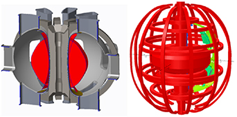
Figure 1. A liquid metal experimental reactor (left); magnet system in a low aspect ratio compact spherical tokamak NSTX-U (right).
Download figure:
Standard image High-resolution image2. Solenoid design
2.1. Design parameters
The solenoid design is focused on improving coil winding pack current density. Our aim is for the next step compact fusion reactor where limited space is available in in-board TF leg radial build. The coil's structural integrity is maintained via clamping at the outer diameter without an expensive and error-prone process for epoxy impregnation. For in-house testing, the subscale solenoid configuration is limited by the maximum inner diameter of the 7'' cryogenic Dewar available for in-house cryogenic test setup.
A total of eight 1.5'' diameter mini-coils with and without wire sleeve and fiberglass tape insulation, as well as two 5'' diameter subscale solenoids of no turn-to-turn insulation but with interlayer fiberglass insulation were designed, wound, heat treated, and assembled on the test stand to investigate critical current performance of non-impregnation, Non-NI and NI superconducting coils. The non-NI mini-coil was wound with a S-glass sleeve-insulated Nb3Sn wire of 0.81 mm diameter of ITER-type, manufactured by Luvata, and supplied to us by the US ITER Office at Oak Ridge National Laboratory. The layer insulated NI (LNI) coils have no turn insulation. The no-turn and no-layer insulation NI coil has three layers of winding with over 150 turns in the winding pack to achieve a ∼600 A mm−2 winding pack current density at ∼700 A of operating current. The 5'' diameter subscale prototype LNI solenoids have ∼1110 turns to generate over 3 T magnetic fields at the center of bore at ∼500 A operating current level. Figure 2(a) presents the cross section of the large solenoids and figure 2(b) presents the cross section of the mini coils, coil forms and end copper rings used for mechanical support. Table 1 presents the Non-NI, LNI and NI coil design parameters. Compared to the non-NI coils, more turns can be packed in the solenoid winding for the LNI and NI coils. The current density Jwp listed in table 1 is only taking into account the difference in the number of turns packed in the coil but not taking into account the difference in actual as-built outer diameter from insulation in the radial build.
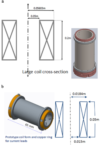
Figure 2. (a) Cross section and winding pack dimension of the large solenoid (left—half the diameter of the NSTX OH solenoid); coil former with end copper rings (right). (b) Cross section of mini-solenoid coils (right); coil former and end copper rings for coil leads (left).
Download figure:
Standard image High-resolution imageTable 1. Design parameters for the subscale solenoids.
| Parameters | Non-NI mini | NI mini | Larger NI |
|---|---|---|---|
| Inner diameter (mm) | 30 | 30 | 100 |
| Outer diameter (mm) | 36.8 | 36.8 | 112.1 |
| Winding height (mm) | 43 | 43 | 208 |
| Number of layers | 3 | 3 | 5 |
| Number of turns | 132 | 153 | 1080 |
| JWP (A mm−2) | 632 | 733 | 455 |
| Inductance (mH) | 0.45 | 0.61 | 64 |
| Operating current (A) | 700 | 700 | 507 |
| Central magnetic field (T) | 2.13 | 2.49 | 3.04 |
| Stored energy (J) | 110 | 150 | 8180 |
| Quench time constant (s) | 0.04 | 0.03 | 0.2 |
| Quench temperature (K) | 54 | 54 | 125 |
Table 2 presents the as-built Non-NI and NI mini coil parameters. A total of 8 mini coils were wound, heat treated. The A-coils listed in table 2 are NI coils without either turn or layer insulation; B-coils are LNI coils with two layers of S-glass wrap between layers, and the C-coils were fully insulated and wound with S-sleeve insulated wire and two layers of S-glass wrap between layers. As shown in Rows 1 & 2 of table 2, the winding pack current density Jwp in the NI coil is over 50% higher than that in the non-NI coils when the as-built outer diameter of the coils was considered. Table 3 presents the as-built larger NI coils (LNI with 5-layer in total with layer glass wrap).
Table 2. As-built mini-coil parameters; ID/OD in mm, L is total wire length; Jwp is expected winding pack current density (A mm−2).
| A1 | A2 | A3 | B1 | B2 | B3 | C1 | C2 | |
|---|---|---|---|---|---|---|---|---|
| ID | 30.0 | 30.0 | 30.0 | 30.0 | 30.0 | 30.0 | 30.0 | 30.0 |
| OD | 39.0 | 39.0 | 39.0 | 40.8 | 40.8 | 40.8 | 42.0 | 42.0 |
| Jwp | 550 | 553 | 553 | 464 | 455 | 455 | 358 | 355 |
| # turns | 152 | 153 | 153 | 154 | 151 | 151 | 132 | 131 |
| L (m) | 18.3 | 18.4 | 18.4 | 19.1 | 18.8 | 18.8 | 16.7 | 16.6 |
Table 3. As-built larger NI coil parameters. The 1 A coil is a practice winding while the 2 A coil winding was packed with ∼3% more turns than the 1 A practice coil.
| ID (mm) | OD (mm) | Jwp (A mm−2) | # turns | L (m) | |
|---|---|---|---|---|---|
| 1 A | 100.0 | 110.2 | 518 | 1084 | 361.4 |
| 2 A | 100.0 | 110.2 | 535 | 1119 | 373.1 |
Figure 3 presents the magnetic field and the winding pack stress distribution in the larger LNI solenoids. The maximum central field on the coil bore is ∼3.1 T and the maximum Von-Mises stress on the coil winding pack is <50 MPa. The max stress will be higher in this case without impregnation as turns in the winding pack act more independently. The max hoop strain is less than 0.05% in the winding pack. The max temperature during coil quench for the larger solenoid is conservatively estimated to be ∼125 K (adiabatic heating of the winding pack cold mass).
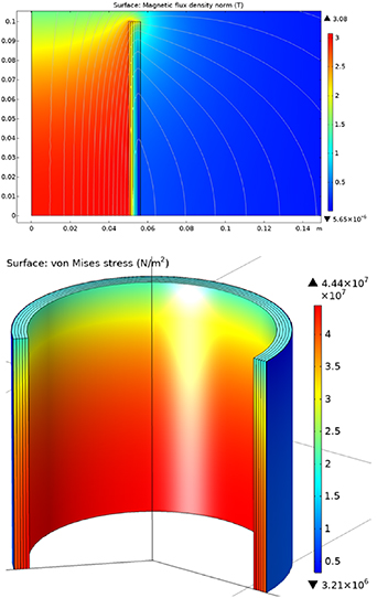
Figure 3. Magnetic field (top) and stress distribution (bottom) in the subscale solenoid coil (half is shown above midplane).
Download figure:
Standard image High-resolution imageThe coil winding pack is designed with outer clamping strips as structural supports to ensure structural integrity in the non-VPI scheme. To enhance winding efficiency and radiation tolerance, a trade-off between cost and performance is investigated while design was focused on more radiation tolerant coils to reduce the usage of organic insulation. The improvement of coil packing factor for higher current density is thus maintained in the coil build.
2.2. Wire type and length limit
The US ITER office supplied us with a significant number of spools of Luvata Nb3Sn wires that were leftover from the TF coil cable-in-conduit (CIC) conductor fabrication. These left-over wires are less than 500 meter of continuous length per spool. The maximum critical current Ic and the N-value of this wire is reported to be 269.4 A and 30.4 respectively at 4.2 K, 12 T. To avoid complication of conductor joints for making prototype coils, we limited the wire length in the coil design to be within a continuous winding length of 450 meter based on the length limit. The technical specification of an internal tin Nb3Sn wire for ITER and measured performance on the Luvata wire can be found in [33].
3. Simplified coil fabrication
3.1. Coil winding
The stainless steel coil formers, the steel and copper rings at ends were machined and assembled first for coil winding. A special coil winder was designed for the coils to be wound by a winding handler fixed on a workbench table located in the TFTR basement at Princeton Plasma Physics Laboratory. Winding of these coils was performed slowly at a speed of a few turns per minute on a small hand winder with an automatic turn counter. An uniform tension of about five pounds was applied by a standard weight set. For mini coil fabrication, one wire spool was shipped to Bruker OST, LLC in Carteret, NJ for an initial insulation braiding prior to winding of the fully insulated coil. The Nb3Sn wire of ∼100 m long for the Non-NI coil winding was cleaned, braided with an S-glass sleeve, and inspected with an eddy current method for defects. As a result, the process added 0.130 mm nominal thickness to the 0.81 mm diameter of bare wire. Two Non-NI mini coils and six NI mini-coils (with and without layer insulation) were wound. Two larger NI solenoids of the same wire (no turn insulation but with layer insulation) were wound using the same winding platform. Wires were cleaned with alcohol during winding. Wires at the coil ends were sand-blasted for removal of chrome plating to ensure good electrical contact between the superconducting wire and the copper leads for efficient current transfer at the solder joint with the current leads. Figure 4 presents a comparison between conventional coil fabrication and the simplified fabrication used here. The simplified fabrication process has cost and performance advantages in non-fusion applications such as high field NMR and MRI.
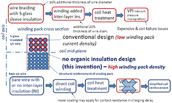
Figure 4. Simplification of NI coil fabrication in comparison with conventional coil fabrication to improve radiation resistance and reduce fabrication cost while enhancing winding pack efficiency.
Download figure:
Standard image High-resolution image3.2. Heat treatment
The mini NI, LNI, Non-NI coils and larger subscale LNI coils, along with Nb3Sn ITER barrels, witness wire samples were heat treated in a vacuum furnace initially used for high temperature furnace brazing. The temperature setup for the heat treatment was automatically controlled following standard ITER specification on coil heat treatment to ensure consistency and comparability. ITER standards and ITER procedures were followed exactly for the heat treatment to avoid ambiguity and uncertainty. Tin leak was observed in two mini-coils after heat treatment and test indicated a performance degradation of these defective coils. Figure 5(a) shows the larger LNI coils in the vacuum furnace and the coil after heat treatment. Figure 5(b) shows the heat treated mini Non-NI, LNI and NI coils.
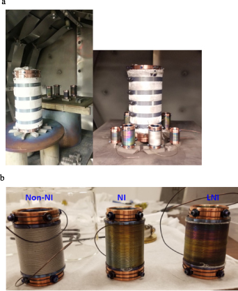
Figure 5. (a) The subscale prototype solenoids in the vacuum furnace after completion of vacuum heat treatment process. (b) Heat treated Non-NI, LNI and NI mini solenoids.
Download figure:
Standard image High-resolution image3.3. Coil structural reinforcement
Since no epoxy impregnation was applied on the solenoids for enhancing radiation resistance and winding efficiency, a new design of coil support structures was needed to ensure structural integrity of the winding pack. One approach used here was to apply stainless steel clamping shells onto the coil pack outer diameter during winding and after heat treatment. A careful control of the clamp tightening force was needed to avoid potential damage to the heat treated coils while minimizing wire movement during current ramping. For the mini coils, a highly adhesive and cryogenics compatible glass ribbon wrapping tape was used on the outer surface of the winding pack. The wrapping tape was hot-melt rubber adhesive, with excellent resistance to solvents and resistance to tearing force of 260 N per 10 mm. This proved sufficient for the mini-coil testing.
4. Cryogenic testing
4.1. Wire performance validation
Three standard ITER barrels were machined for wire characterization and validation of the coil heat treatment process. The witness wire samples assembled on the heat treated ITER barrels were shipped to the National High Magnetic Field Laboratory (NHMFL) in Tallahassee, FL for critical current characterization under high magnetic fields. The standard electrical voltage criteria of 0.1 uV cm−1 was used for the critical current measurements. The wire N values were obtained from a linear fit of log-log plot of data between 0.1 uV cm−1 and 1 uV cm−1. Two pairs of voltage taps of 50 cm and 25 cm, respectively, were used. Data from the 50 cm voltage tap were reported in figures 6 and 7 below. The wire critical current reached ∼200 A at 4.2 K, 12 T. The wire N-value of 23–29 was achieved, meeting the ITER specifications. The high field test results validated our in-house wire and coil heat treatment process. The critical current extrapolated at 4.2 K, 3.1 T is near 1000 A, sufficient for the purpose of this sub-scale prototype coil testing.
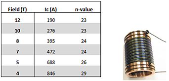
Figure 6. Wire critical current and n-values from in house built ITER barrels tested at NHMFL.
Download figure:
Standard image High-resolution image
Figure 7. Wire critical current (top); voltage current data (bottom) from ITER barrel at 12 T tested at NHMFL (Courtesy of J. Lu).
Download figure:
Standard image High-resolution image4.2. Prototype coil testing
The in-house helium cryogenic system for the subscale prototype coil testing was equipped with coil instrumentation for measuring magnetic fields and the liquid helium level in a cryogenic Dewar. The total energy stored in a mini-coil was a few hundred Joules at 700 A full current. A 7" inner diameter Dewar of ∼30 l liquid helium capacity was available for the test. A high voltage power supply was initially used for current ramping with manual control of the ramp rate, but more precise control of the current ramp proved challenging. It was then replaced by a new 900 A low voltage DC power supply (MagnaPower Electronics) for a better control of the ramp rate. The water cooled copper bus bars were assembled onto the test probe for active cooling of the test probe during current ramping via a 12 °C chilled water system. A pair of meter-long, ⅝" diameter copper tube current leads designed for 700 A operation was assembled to the test probe, along with a Hall probe and a Gauss meter for magnetic field measurements. The test probe also included a helium flow meter for monitoring the liquid helium level in the test Dewar. Liquid nitrogen was used for initial cool-down of the Dewar and the test assembly. The liquid helium was then transferred to the Dewar for final cool-down. Once there was no boiling, the current was then ramped slowly at a rate of ∼5 A per minute. Figure 8 illustrates the in-house built coil test setup and the test stand. We were able to achieve 300 A to generate a central field of less than one Tesla on a non-NI mini coil. Less than 250 A current was achieved on a layer-insulated LNI coil. A number of training (∼5) was observed for the coil to reach one Tesla central field at the coil bore during testing. It was observed during initial testing that coils were unable to take a 50 A per minute fast current ramp likely due to a combination of cooling inefficiency in the copper leads (∼3 W higher heat loads); delay in charging the NI coil; lack of equipment control on ramp rates; and inadequate data acquisition to capture the onset of NI coil quench before current began sharing among turns, i.e. better time resolution for coil near critical current voltage-current characteristics. The larger LNI coil was also tested in-house, and current was ramped up to over 100 A; the central field measured reached 0.67 T, consistent with the design value. A clear time delay in the field measurement typically observed in NI coils was recorded in the Hall probe measurements. The coil quenched beyond 100 A, but a clear current sharing among turns in the NI coil was also observed, which implies thermal stability and robust quench protection in coil quench performance. The coil can be ramped up to 100 A again without any issue, which implies no damage to the coil.
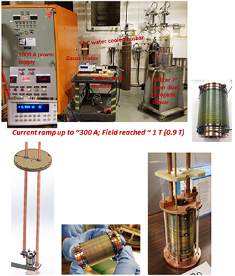
Figure 8. Experimental setup for in house coil testing (top), the NI mini-coils (bottom) on the test stand and the larger LNI coil.
Download figure:
Standard image High-resolution imageFurther testing of larger LNI coils needs a more effective quench detection and protection system. A circuit design for quench detection and protection was thus developed for next NI coil testing. Multiple voltage taps and thermal sensors were implemented and integrated into the larger LNI coil for further testing.
One challenge in testing a NI coil is managing the current ramping while maintaining thermal stability in a cryogenic environment. Figure 9 presents the schematic diagram of the experimental layout where a stainless steel cryogenic Dewar was used as a test container to house the experiment, with a proper liquid helium containment and cryogen pumping. A vapor-cooled current lead was used to submerge the coil in liquid Helium and electrically connect it to the power source.

Figure 9. Block diagram for the circuit and instrument configurations for prototype coil testing.
Download figure:
Standard image High-resolution imageThree mini coils (non-NI, LNI and NI) were shipped to the University of Geneva in July 2017 for a coil performance validation via a critical current test campaign in a test facility with background magnetic fields. A special mini-coil insert adapter was designed, machined, and assembled onto the 92 mm bore, 25 T Geneva magnet test probe with efficient HTS current leads in the test facility. Figure 10 presents the mini-coil adaptor and test probe assembly. Figure 11 presents test probe instrumentation. The mini-coil was tightly wrapped on its outer layer of the winding pack with highly adhesive rubber ribbons for enhancing structural integrity. The coils were instrumented with two pairs of identical voltage taps and assembled together with a pair of NbTi leads connected to the HTS leads. Two mini-coils (NI and LNI) were tested with and without a background magnetic field, but unfortunately one of the two coils (NI) was found defective, possibly due to a tin leak during heat treatment. The test results clearly indicated that less than 200 A coil current was achieved. The second mini coil (LNI) performed extremely well during the test, considering the fact that there was no epoxy impregnation and no organic insulation applied to this coil. At a ramp rate of ∼50 A per minute, coil experienced a first quench at ∼600 A during current ramping; a clear voltage signal was detected, but the voltage spike quickly returned while the current continued to ramp up and reached about 700 A to generate ∼2.65 T central magnetic field. This is ∼83% of the wire critical current. Figure 12 presents LabView screenshot of the voltage tap waveforms. When the coil was discharged and charged again, the current reached >600 A again and experienced the second quench. After that, a 3 T background field was applied onto the mini coil insert. The insert current reached up to 530 A before it experienced a current quench, then the coil continued to be overcharged at a higher current after the quench. Unfortunately, the third min coil arrived at Geneva was not tested due to inadequate availability for the magnet time.

Figure 10. The mini coil adaptor and test probe assembly for Geneva test.
Download figure:
Standard image High-resolution image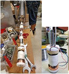
Figure 11. Mini coil instrumented and assembled onto the test probe (left) and the LabView data extraction of the coil critical current performance during current ramp testing.
Download figure:
Standard image High-resolution image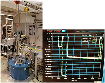
Figure 12. The Geneva test facility (left) and voltage tap waveform (right).
Download figure:
Standard image High-resolution imageFigure 13 presents the load line of the LNI mini-coil and critical current under various magnetic fields from the ITER Nb3Sn wire measurement. Even for an impregnated Nb3Sn coil, over 80% of wire critical current achieved in a coil design is sufficient validation of the coil performance. The no-insulation coils achieved 83% of wire critical current with a much simplified coil fabrication process. The new coil was also much more efficient and enhanced radiation resistance without organic insulation, as the magnet with high winding pack current density shows in table 1.

Figure 13. Critical current against the magnetic field of the mini-coil design load line (red) and the wire critical current (blue). Results showed that no-insulation, no epoxy impregnation coil achieved 83% of the wire critical current.
Download figure:
Standard image High-resolution image4.3. Analysis on coil test data
Data obtained from the first test campaign in collaboration with the University of Geneva were analyzed to understand stability of NI coils [34,35]. The data described behavior of two coils at varying background magnetic fields and peak currents. The test data included voltage measurements along the coil winding at ends and in the middle layer used to approximate the electric, magnetic field estimated from coil parameters and current, the voltage and current evolution; background magnetic field, and force on the coil. Analysis began with the first of two coils at the zero background magnetic field, with a focus on readings of the voltage (or electric field), input current, and voltage taken near a quench in the NI coil. Force data was near constant compared to noise in experiments, and any sudden changes were not well correlated with other events; these data were thus ignored.
The buildup of electric field in the coil prior to quenching is the most interesting result, as it is indicative of transient currents and instabilities [35], which eventually lead to a quench. The other primary finding was the observation of a field 'backlash' after quenching. This was due to the protective circuitry cutting off the power source since the coil, acting as an inductor, opposed any change in current and produced a negative electric field until current in the coil was depleted. This process gave a timescale of the discharge of current from a coil of several seconds, which verified the common problem of preventing excessive ohmic heating in a coil that is no longer superconducting. Upon further inspection, however, other problems existed with this coil. The peak current was only 140 A in a superconductor that should be able to handle at least 1 kA in self-fields. This experiment was repeated with the same coil with 1 T and 3 T background fields with peak currents near 130 A. A higher background field is expected to lower the peak current, so these results are consistent with expectation. In addition, the ratio of peak quench electric field to backlash field was as high as 0.8 for these experiments; if this ratio were to get too high, even more ohmic heating could result. Therefore, a balance must be achieved between quick current dissipation after quench and preventing large electric fields created within the coil. In contrast, mini coil #2 (LNI) proved to be much more robust, featuring peak currents as high as 700 A. However, it was strange to see zero recoil voltage as shown in figure 12; likely due to current sharing in the NI coil, perhaps a turn short due to high voltages developed in the vicinity of coil critical current that saturated measurement equipment. As expected, the background field had a pronounced impact on the peak current while no background field allowed currents up to 700 A, a 3 T field only allowed about 530 A.
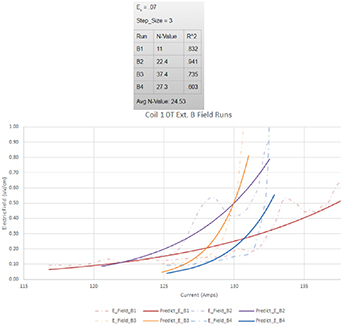
The typical n-values for the NI coil tested were extended from ∼15 to 40. The n-values tended to decrease with increasing applied external magnetic fields as shown in table 4. As a result of no-insulation, wires were able to slip across each other via frictional contact within the coil winding. At the cryogenic temperature, the wire heat capacity was low, so the frictional heating could be greatly magnified. Therefore, for the first few runs, n-values were lower than in the later runs, and the take off region was elongated as the wires had not settled down within coil winding. Without external magnetic fields, the voltage in the coil #1 (NI) departed from zero gradually and significantly before quenching occurred between 130 A and 137 A shown in figure 14. The quenching occurred more sharply at higher applied external magnetic fields. Quenching also appeared to occur at lower amperages as the external magnetic field increased. For mini coil #2 (LNI), quenching occurred at lower amperages as the external magnetic field increased, but it occurred at much higher amperes than the first coil. The coil quenched more suddenly with little to no departure in the voltage preceding. The external magnetic field had little effect on the general voltage current curve shape for coil #2.
Figure 14. I–V curve of NI coil showing graduate normal transition.
Download figure:
Standard image High-resolution image
Table 4. N-value extracted from coil #1 (NI) and coil #2 (LNI).
| External B field (T) | 0 | 1 | 3 |
|---|---|---|---|
| N-value (coil #1) | 24.5 | 19.4 | 16.0 |
| N-value (coil #2) | 30 | 30 | N/A |
5. Measurement equipment
The crucial component in our measurement suite was the Data Acquisition System from Astro-Nova, which can take up to 18 analog inputs with extreme precision and speed, five significant figures at 50 kHz. A differential amplifier input at each port was available to increase precision for signals below 200 mV. This system was used to monitor voltage drops across multiple parts of the coil, since it was unfortunately not designed to collect digital input. A Keysight multimeter was used in current measurement mode, which was also capable of five digits of precision at 50 kHz. This was placed with a 1 kΩ resistor in parallel with the dump resistor to sense approximately 10−5 of the current being dumped due to the creation of a current divider. These two fast electrical measurements allowed us to resolve the dynamics of a quench with several integrated electric field measurements and direct current measurements. The remainder of the equipment was monitored from a desktop running a LabVIEW automation program. Input current and voltage were monitored using the digital output from the power supply from MagnaPower Electronics. Similarly, the magnetic field in the center of the coil as well as the temperature along several parts of the coil were monitored by a Lakeshore Gaussmeter with Hall probe and a Lakeshore temperature monitor with thermal diodes, respectively. Prolific Serial-USB converters and null modem cables were used to interface the instruments with a computer.
6. Conclusion
Reliable and robustly operated high field, high current density superconducting magnets are the crucial component to achieve burning plasma for the next generation magnetic confinement fusion reactors or pilot plants. To close the gap between advances in high field magnets and next step fusion application, a compact winding of irradiation tolerant Nb3Sn superconducting coils of no insulation and lower fabrication cost of simplified process has been tested. The Nb3Sn NI coil made at Princeton University Plasma Physics Laboratory was successfully tested at University of Geneva high field magnet facility. The Nb3Sn coils of simplified fabrication process without vacuum pressure impregnation reached up to 83% of the wire critical current, and subsequently reduced cost while maintaining the winding pack structural integrity. The overall current density in the coil winding pack was near 600 A mm−2 under the coil self-field of ∼3 Tesla. Simplifying the fabrication process is critical to reduce cost of non-fusion magnets for the NMR and MRI. The test results showed that the in-house built Nb3Sn coils with reduced insulation improved its performance with an increased coil winding efficiency and structural integrity. The results also brought several possible improvements to be made to magnet operation and fabrication. For coil critical current testing, electrical measurements must be made at a sufficient frequency, at least a kilohertz, to fully resolve the dynamics of a quench and to detect a quench reliably in a timely manner. In addition, the current during discharge could be monitored with a simple resistor and an ammeter in parallel with the dump resistor. The resistance value of this dump resistor must be balanced to take the majority of the energy released in coil discharge while not introducing a dangerously large voltage across coil terminals. In terms of quench detection, an optical system utilizing optical fibers and either terahertz sensors or spectrometer arrays could spatially resolve a quench before it occurs. In addition, for fabrication, other hexagonal configurations of winding cables could result in superior performance and reliability of the magnets.
Acknowledgments
This work was supported by the U.S. DOE contract No. DE-AC-02-09CH11466, DOE SULI Program at Princeton Plasma Physics Laboratory, and Princeton-University of Geneva International Research Partnership Grant. The project is being accomplished through a collaboration of laboratories and universities.
Data availability statement
The data that support the findings of this study are available upon reasonable request from the authors.