
Abstract
Context
Automotive software architectures describe distributed functionality by an interaction of software components. One drawback of today’s architectures is their strong integration into the onboard communication network based on predefined dependencies at design time. The idea is to reduce this rigid integration and technological dependencies. To this end, service-oriented architecture offers a suitable methodology since network communication is dynamically established at run-time.
Aim
We target to provide a methodology for analysing hardware resources and synthesising automotive service-oriented architectures based on platform-independent service models. Subsequently, we focus on transforming these models into a platform-specific architecture realisation process following AUTOSAR Adaptive.
Approach
For the platform-independent part, we apply the concepts of design space exploration and simulation to analyse and synthesise deployment configurations, i. e., mapping services to hardware resources at an early development stage. We refine these configurations to AUTOSAR Adaptive software architecture models representing the necessary input for a subsequent implementation process for the platform-specific part.
Result
We present deployment configurations that are optimal for the usage of a given set of computing resources currently under consideration for our next generation of E/E architecture. We also provide simulation results that demonstrate the ability of these configurations to meet the run time requirements. Both results helped us to decide whether a particular configuration can be implemented. As a possible software toolchain for this purpose, we finally provide a prototype.
Conclusion
The use of models and their analysis are proper means to get there, but the quality and speed of development must also be considered.
1 Introduction
During the last decades, thousands of primarily software-controlled functions were included in modern cars, which are executed on many electronic control units (ECU). Their particular characteristics reach from non-safety-critical to safety-critical and real-time-critical functions. Driving forces for this development were: (i) safety requirements, (ii) customer demands for more comfort and the newest infotainment systems, and (iii) advanced driver assistance systems allowing to reach higher levels of driving automation (cf. [88]).
1.1 Status quo
These driving forces led to the current electric/electronic (E/E) architectures best characterised as historically grown, mostly federated, partly integrated architectures with often pragmatic, cost-efficient, and ad hoc solutions. More than 100 purpose-built ECUs realise in an interplay of timed signals sent via heterogeneous bus systems (e. g. CAN, LIN, FlexRay, or Ethernet) with gateway structures the functions’ behaviours. Current automotive software architectures mainly follow the idea of static communication paths in line with the AUTOSAR Classic Platform [7]. Here, distributed software applications are already strictly bound to ECUs at the development stage to enable exchanging messages between them. This, however, impairs the possibility of developing both parts independently of each other. This ECU or message-centric focus cannot cope with future challenges in automotive software and systems engineering. To promote faster adoption of innovative features and services, more agile development methodologies need to be built into established processes. A lot of research effort is currently put into developing all-new E/E architectures that will be even better equipped for future trends, innovations, and new technologies [49, 95]. We see three fundamental changes in the automotive industry requiring new approaches for development at design-time as well as for operation during run-time:
Challenge 1—Automation
 : Driving at higher levels of driving automation (i. e., levels 3–5 according to SAE J3016 [88]) requires a particular focus on functional safety and security. Liabilities switch from the driver to the car vendors in automated driving beginning with level 3. At conditional automation such as highway pilots, the car fully controls in a particular operational situation the vehicle (longitudinal and lateral movement) without the need to be monitored by the human driver. Regulatory authorities will require by law to continuously improve those safety-critical functions, i. e., fix possible errors and update crucial components to the state-of-the-art. Necessary machine learning models are trained in OEMs’ backends and need to be delivered continuously.
Challenge 2—Intelligence
 : Machine learning is an emerging and cross-disciplinary field that is making great strides in innovative and automated vehicle functions. Sophisticated smart capabilities and highly personalised functions are no longer a future vision but can already be found today. Machine learning requires a lot of data to be useful. E/E architectures need to be able to transmit, store, and process this data, which poses requirements on bandwidth, computing power, and communication topology.
Challenge 3—Connectivity
 : Experts are sure that reaching level 5 of driving automation can only be achieved through car-to-x (car, infrastructure, backend) communication. Vehicles are in use for more than 15 years on average. Information technology improves rapidly during that period: E. g. an encryption algorithm used for backend or car-to-car communication can become outdated and not be considered secure anymore and has to be updated after almost a decade. Hence, possible attack surfaces need to be mitigated continuously.
Table 1 summarises essential aspects that have already partially changed today, but most will change—that is our firm belief—in the future.
1.2 Future perspective
To cope with these challenges, besides a scalable and performant computing platform, software architecture plays a critical role. When designing a system’s software architecture, the primary goals are to develop safe, performant, flexible, adaptive, and maintainable systems. Service-oriented architectures (SOA) are known for supporting the design of flexible systems. In contrast to existing Controller Area Network (CAN)-based approaches combined with AUTOSAR Classic, service-oriented approaches allow for late binding at run-time facilitating the integration of new functionalities and services at run-time.
Automotive OEMs are on the way to steadily substitute legacy communication by including more and more IP-based communication technologies into their vehicles, which supports a better separation of software and hardware. At the very core of the presented approach is the principle of service-orientation. The combination of IP-based communication and SOA allows to add, update, remove, or start and stop services at run-time. Moreover, network engineers’ workload is reduced to a minimum since they do not need to do all the way from signals down to messages manually, but only define the service provision and consumption relationship and their interaction pattern.
1.3 Scope of the paper
In Fig. 1, two applications \(\mathsf {App}_1\) and \(\mathsf {App}_2\) are logically interacting. (a) In the first case—the traditional way—by exchanging signals that manually need to be mapped into protocol data units (PDUs), which in turn are mapped to CAN messages. This is a time-consuming and error-prone process, hindering dynamicity and thus reconfiguring the network topology at run-time. The resulting communication infrastructure is then static over the system’s lifetime. (b) In the second case, by establishing a service provision/usage relationship and their pattern of interaction, which we are discussing and proposing in this paper. We distinguish between two principle communication patterns (cf. Fig. 2):
-
(1)
Request/Response, i. e., a method is called and a result is returned and
-
(2)
Publish/Subscribe, i. e., a server first publishes a service and a client subscribes to it. Then, either periodically or at each change event at server-side, the client gets notified.
In a service-oriented architecture, services provided by a server can be looked-up in a service registry and used by clients (cf. Fig. 2). In a request/response pattern, the client sends a request to the server, which in turn responds to the client. A method-call is realised in this way. In the publish/subscribe-pattern, the server first publishes a service which can be found by the client. The client then subscribes to the service and gets either periodically notified or by a change at server-side. Technically, this functionality is achieved using, for instance, the SOME/IP [96] or DDS [71] middleware in combination with the AUTOSAR Adaptive Platform (AP) standard for Ethernet-based topologies.

a Classic signal to message mapping: Logical signals are grouped into PDUs (protocol data units), which in turn are mapped to CAN messages. b In contrast to service binding in a SOA approach. Here, only the interaction patterns are defined. The rest is done automatically

Interaction patterns: Services can be published and then be found in order to subscribe to them. The interaction is performed either by applying a request/response pattern or subscribing to a service that then notifies the client(s) on a periodic or sporadic basis
SOA paradigms help to decouple software and hardware development to a large extent, facilitating fast and light-weight software updates in a fast-moving agile development process based on the idea of continuous software engineering [14]. Services will replace the former centricity on signals and ECUs in a strongly model-driven and model-focused approach shortly. On the one hand, we use models early in the development process for verification, simulation, and analysis purposes, and, on the other hand, as a basis for the generation of test cases in a model-to-model transformation fashion. As the scope for this paper, we aim to solve three challenges associated with service-orientation by model-based techniques:
- (C1):
-
The deployment problem for a service-oriented architecture onto an overall future E/E architecture,
- (C2):
-
the assessment of timing properties with an emphasis on the idea of run-time reconfiguration, and
- (C3):
-
the transition of platform-independent architecture models into a platform-specific software development process in line with the AUTOSAR Adaptive standard.
Before we go into the guiding research question, the context and embedding within a pre-development project at the industry partner should first be addressed. In this pre-development project, the question of a future centralised E/E architecture for automated driving at level 4 arose. To this end, two independent development strands were pursued: On the one hand, an onboard network topology model was presented as a draft, and on the other hand, the specialist departments provided the first indications of the necessary time and memory requirements. Both artefacts served as a basis in this pre-development project.
The guiding research question is derived from this:
In a pre-development project, can the unification between a specification of an independently created novel E/E architecture and initial estimates of the resource consumption of the service-oriented software architecture succeed and a system specification be derived from it?
The following three framework conditions must be met: (1) The processor, memory, and safety constraints must be observed, (2) the communication behaviour at bus level must ensure timely data provision, and (3) the architecture must be implementable in a software development process.
Contributions This paper provides the following contributions:
-
(i)
Platform-independent meta-model for service-oriented architectures;
-
(ii)
methodology for deploying corresponding platform-independent models on a centralised E/E architecture;
-
(iii)
embedding of the gained results in a platform-specific software development process.
This paper is an extended version of the MODELS 2019 paper [69]. We have extensively revised and extended the manuscript compared to the previous work in different directions:
-
(i)
We have extended the related work;
-
(ii)
We now demonstrate how a model-based software design approach based on the AUTOSAR Adaptive Platform looks like. To do so, we show the transition from a platform-independent model to a platform-specific one—in our case AUTOSAR Adaptive;
-
(iii)
Moreover, we demonstrate how to generate test cases already in an early design step in order to safeguard the architecture;
-
(iv)
We have extended our experiments and evaluation by also considering the connection of the proposed centralised architecture in combination with legacy sub-systems, which is of great importance in an industrial context;
-
(v)
This paper also illustrates the use of the industry-standard PREEvision MBSE tool with which we have seamlessly evaluated the work.
Outline The remainder of this paper is structured as follows. Section 2 summarises related work followed by the main approach in Sect. 3. In Sect. 4, we present the conducted evaluation of our approach. Finally, we discuss the results and conclude in Sects. 5 and 6.
2 Related work
Related to our work are the fields of model-based architecture design and automotive service-oriented architectures. The first field is relevant to us because the underlying concepts of model-based design in general and architecture description, optimisation and analysis, in particular, can be used to address the first two framework conditions. The second area addresses related work according to the third framework condition (cf. Sect. 1.3). Here, we want to present the status quo in terms of technologies, standards, and the overall implementation process for realising the concept of service-oriented communication in an automotive way.
2.1 Model-based architecture design
We structure the field of model-based architecture design into three parts: (1) The development and usage of architecture description languages, (2) the notion of component-based architectures, which is especially relevant to the design of software architectures, and (3) architecture analysis methods for architecture verification and validation.
2.1.1 Architecture description
The concept of architecture description is standardised by the ISO 42010 [45] and introduces the notion of architecture viewpoints. Viewpoints define modelling techniques that support the comprehension of specific parts (e. g. the software architecture) or specific activities (e. g. the software integration) within the system architecture’s development process. The application of these modelling techniques then finally provides an architecture view that supports architecture stakeholders, e. g. software architects, for their concerns. Over time, instances of this idea have been introduced. All of them focus on an approach that consists of different abstraction levels, e. g. in order to separate functional and implementation-related parts such as the software architecture from each other. Broy et al. [15] and Dajusren [22] developed approaches for architecture description frameworks that facilitate deriving viewpoints based on abstraction levels. In addition, they focused for each abstraction level on the distinction between structural and behavioural aspects. With a focus on process-related viewpoints, Pelliccione et al. [74] recently introduced an architecture description approach related to development process activities like continuous integration, deployment, and automotive software ecosystems. All of them are rather new for the automotive domain. For the more general domain of embedded systems, Pohl et al. [75] introduce the SPES_XT (Software Plattform Embedded Systems) methodology, which neglects a process view and implementation planning. In addition, several Architecture Descriptions Languages (ADLs) and reference architectures made their way into practice (cf. [24] and [79]). Here, the idea of different abstraction levels is implemented by the Electronics Architecture and Software Technology—Architecture Description Language (EAST-ADL) [26] and the Electric Electronic Architecture—Analysis Design Language (EEA-ADL) [47]. The latter is the architectural description language underlying the MBSE tool PREEvision, which we use for this work. Although modelling with EAST-ADL addresses important aspects in vehicle development, practical acceptance in the automotive industry is low. One reason for this may be that the last (alpha) version of EAST-ADL2 is dated 2013 and therefore does not yet take AUTOSAR Adaptive Platform into account. For the more general domain of embedded systems, the MARTE [73] approach and the MechatronicUML [25] have been developed. All of them rely on the MOF [72] framework. Especially common in the avionics domain, the Architecture Analysis and Design Language (AADL) [30, 87], standardised by the Society of Automotive Engineers (SAE), is used in combination with respective tools (e. g. OSATE, the Open Source AADL Tool Environment [19]) to model, analyse, and verify the design and architectural models. Most of the ADLs listed here serve similar goals: Modularisation and hierarchisation of component descriptions and architectures to ease the development of highly complex, usually embedded, systems. The approach presented here could also have been realised with one of the other approaches. AADL would have been a good choice here. However, since the MSBE tool was set in this pre-development project at the industry partner, there was no choice.
2.1.2 Component-based architecture
The notion of component-based design is the inherent idea of every software architecture. Especially for the domain of embedded and automotive systems, dedicated component models have been introduced. Their main distinction to other domains is the necessity to reflect real-time and functional safety requirements. From the industry perspective, the de-facto standard is given by AUTOSAR. Especially in terms of formal component models, complementing approaches from the academic world have been published. Kugele et al. [53] present one approach that combines component-based architectures and contract-based design with a focus on functional safety. A more general approach in terms of focusing on a variety of non-functional properties is given by Damm et al. [23] in the form of their rich component framework. Especially for the concern of deterministic execution behaviour, the actor [59] and the reactor model [60] provide applicable ways for the overall domain of embedded systems. Lastly, another variation of an automotive software component in the form of agents is present. Here, Sillmann et al. [85] provide an approach focusing on describing the electric powertrain software architecture as an agent-based system. Of course, the architectural approaches mentioned above also use the term components to describe both the system architecture and the system behaviour: AUTOSAR, FOCUS, AADL, UML, SysML, or the Palladio Component Model to mention some of them. To the best of our knowledge, none of the component models mentioned is used in daily productive use in the automotive industry (except for AUTOSAR, UML, and SysML, of course). This does not necessarily mean that the approaches are not suitable, but for productive use, the tools used in particular must be mature.
2.1.3 Architecture optimisation
Traditionally, the automotive industry uses optimisation methods in various areas during vehicle development. Business management questions (e. g. cost models [6, 8, 9, 78]), questions concerning mechanics and electrics (e. g. car body optimization [86], hybrid powertrain [31], or EMC [80]) were often addressed and answered, to name only a few. In recent years, however, researchers and practitioners have also been concerned with the reliability of automotive E/E architectures and automatic mapping software components to available ECUs, also referred to in the literature as deployment or allocation. Design Space Exploration (DSE) techniques have often been and still are used for this purpose.
In the following, we concentrate on the optimisation of software architectures in particular. Mertens and Koziolek [64] presented the tool PerOpteryx, which is an optimisation framework for the improvement of component-based software architectures. The tool evaluates the performance of various design alternatives of component-based architectures modelled in the Palladio Component Model (PCM) [10]. It thus supports the engineer during the design process. The idea behind this approach is similar to what we aim for in this paper to support engineers at an early stage of the design process by synthesising and evaluating architectural proposals. These can then be the first indications for a final architecture since they have already been verified. However, in the present work, we focus on a particular use case, namely the early analysis of a software and hardware architecture designed for automated driving. Grunske et al. [39] give an overview of architecture-based methods for optimising the reliability of software-intensive systems. The authors use evolutionary algorithms and multi-criteria optimisation strategies to find good architecture design alternatives with the tool ArcheOpterix [1]. In contrast to the above approaches, we use a two-step procedure in this paper. First, an SMT-based (SAT modulo theories) DSE is performed, and then a simulation-based end-to-end latency analysis is applied for the architecture candidates found. The candidates are the Pareto-optimal results of an optimisation problem and not solutions based on heuristics. In a previous work of one of the authors of this paper, Kugele et al. [50] used integer linear programming (ILP) to optimise the deployment concerning non-functional requirements in combination with an SMT-based scheduling scheme within the COLA toolchain [40]. Furthermore, Meedeniyaa et al. [66] uses a genetic algorithm (GA) in a reliability-driven deployment optimisation of embedded systems. Kumar et al. [57] also use a GA to perform multi-level redundancy allocation. Streichert et al. [90] apply multi-criteria evolutionary algorithms for topology optimisation in networked embedded systems. Lukasiewycz et al. [62] extend this work to enable simultaneous topology and routing optimisation in automotive networks. Their approach is based on SAT encoding, which combines a pseudo-Boolean (PB) solver and Multi-Objective Evolutionary Algorithms. Glass et al. [36] present further improvement. They propose a new algorithm for multi-objective routing with a genetic encoding independent of the underlying network topology. For a comprehensive, systematic literature review on software architecture optimisation methods, please refer to Aleti et al. [2]. Since this work’s main focus was not on developing even better optimisation methods, we have taken a pragmatic approach here and generated the deployment candidates using an SMT-based method. Of course, the tools described above could have been used as well. However, seamless integration into PREEvision would not have been so easy.
2.1.4 Architecture analysis
Model-based approaches provide various analysis techniques besides architecture description in corresponding languages or based on specific component models. In this respect, the main objectives are to derive whether an architecture concept can meet real-time capabilities or functional correctness requirements. Especially for safety-critical architectures, these characteristics are highly demanded. For a generic approach for evaluating and analysing embedded systems, please refer to [33]. Possible approaches are given by model-based timing analysis, simulation techniques, as well as model checking.
Model-based Timing Analysis For the field of model-based timing analysis, the real-time calculus [92] and the SymTA/S (Symbolic Timing Analysis for Systems) approach [82] are widely known and implemented in corresponding tools (cf. [21]). As a contribution during early development phases, the paradigm of logical execution time [28] is helpful and has, therefore, found its way into the field of real-time evaluation for automotive systems. The tool aiT [32] is also used in several domains, including avionics and automotive. aiT computes using abstract interpretation the worst-case execution time of an executable for a given processor model. On the one hand, this approach produces provable upper bounds; on the other hand, however, the gained values are for many situations too conservative [94].
Simulation Techniques We use the tool chronSIM [44] for timing simulation. In general, it does not provide evidence for upper bounds (Which are too conservative in practice). Instead, a practical, pragmatic approach between accuracy, conservatism, and analysis time is found through many simulation runs. For simulation-based approaches, the C++ library SystemC [43], as well as the Functional Mock-up Interface (FMI) standard [68], provide capabilities for the test of system-level behaviour. Besides that, tools such as MATLAB/Simulink [65] or ASCET [29] describe de-facto industry standards for early system-level tests. From the academic world, the tool Ptolemy II [77] that relies on the introduced actor and reactor models is present. With a focus on the power consumption of automotive system architectures, Bucher et al. [18] provide a simulation-based approach using Ptolemy in combination with the Electric Electronic Architecture—Analysis Design Language (EEA-ADL) [47].
Model Checking Also, formal techniques like model checking are widely used in academia and become more and more important for practitioners. The automotive functional safety standard ISO 26262 [46] highly recommends formal techniques at a certain degree of required integrity. AutoFOCUS [34] is a research prototype for model-driven development supporting formal verification capabilities.
2.2 Automotive service-orientation
Model-based design is a widely used methodology for embedded systems design. Numerous tools and languages are available both in an industrial (e. g. SCADE [83] by Esterel Technologies, MATLAB/Simulink/Statechart [91] from The MathWorks, and ASCET-SD from ETAS) as well academia (e. g., MechatronicUML, PCM, FOCUS) setting. Of course, SysML or UML as general-purpose modelling language with its profile for Modelling and Analysis of Real-time and Embedded systems (MARTE) has to be mentioned.
As the second part of the related work, we present publications relevant to the specific field of automotive service-oriented architectures. As a means of structuring them, we build the divisions of modelling methods, implementation-related contributions, and development process-related contributions.
2.2.1 Modelling methods
Broy and Stølen [17] provide one groundbreaking publication for modelling embedded service-oriented architectures relying on formal models for service syntax and semantics. Later on, Broy and Krüger [16] introduced an approach that describes services explicitly by timed streams of data. Malkis and Marmsoler [63] again relaxed this constraint by allowing services to be any computational task. Besides these general contributions to formal service models applicable to embedded systems, automotive-specific work has been published. Recently, Kugele et al. [54] introduced the idea of \(\alpha \)SOA by formalising a framework for different service clusters that partly relies on the formal model of Broy and Stølen [17]. Afterwards, Cebotari and Kugele [20] refined this framework and described their transformation onto the modelling language Franca [27] used in the industry. For specific application domains, Lampe et al. [58] drafted an architecture for automated driving based on services. For the field of safety and failure handling, Bocchi et al. [13] provided an approach that models the concept of run-time reconfiguration in a service-oriented way.
2.2.2 Implementation-related contributions
Middleware concepts are available for the implementation of automotive service-oriented architectures, some of which are also part of the AUTOSAR standard. Two instances in this respect are the scalable service-oriented middleware over IP (SOME/IP) [96], and the Data Distribution Service (DDS) [71] approach. In addition, Android AUTO [37] and the GENIVI platform [3] illustrate solutions dedicated to the infotainment domain. Besides their industry application, researchers have investigated primarily the AUTOSAR compliant solutions SOME/IP and DDS. For SOME/IP and with a particular focus on deterministic service execution, Menard et al. [67] recently provided one approach that relies on the reactor component model [60]. Earlier, Seyler et al. [84] described one approach for timing analysis based on SOME/IP. For DDS, Kugele et al. [51] and Kampmann et al. [48] focused on the potential to integrate new applications based on the idea of containerisation continuously. Besides established technologies such as SOME/IP and DDS, research prototypes for middleware solutions have been developed. As an example, the RACE approach [89] was initialised in 2012. More recently, Lotz et al. [61] published one approach that relies on a run-time environment for microservices. In this work, we are using the SOME/IP as the communication protocol. SOME/IP is part of the AUTOSAR Adaptive Platform standard and supported by the used modelling and simulation tools.
2.2.3 Development process-related contributions
Service-oriented architectures provide abstraction from the onboard communication network. Therefore, of particular interest for car manufactures is the potential to ease and fasten the development process for developing software applications. Work in respect of service-oriented architectures and process-related aspects has been rarely published. Traub et al. [95] draft the idea of an automotive software engineering approach relying on services rather than the classic signal-oriented approach. Obergfell et al. [70] describe an approach for an incremental development procedure that relies on the concept of service-oriented architecture as one primary driver. However, the current state-of-the-art for software and systems engineering still relies on classic signal-oriented architectures. Consequently, this paper’s focus is the development of drafts for service-oriented architectures and their inclusion into a subsequent realisation process. Therefore, we do not focus on introducing new SOA modelling notations but rather using the concepts of modelling in the MBSE tool and the SOME/IP protocol’s service-oriented communication.

The big picture: Modelling, design space exploration, and timing analysis, the transition from platform-independent to platform-specific architecture, software design, and finally validation using testing. The dashed lines indicate that if no candidate solution could be found or timing/bandwidth requirements are not fulfilled, the modelling must be adjusted, for example, by adding further suitable cores or memory units or new network links
2.3 Summary
In this section on related work, we have listed a summary of existing preliminary work. These have been grouped thematically into the main categories of model-based architecture design and automotive service-orientation, each with more detailed descriptions. This thematic selection is also based on the guiding research question and classifies the work accordingly. Our work is partly based on the work discussed and differs; in particular in that it is not a pure research prototype but rather a closer integration into an existing toolchain of the industry partner in a pre-development project on automated driving at level 4. For this reason, some purely academic approaches, in particular, were not usable, although perhaps better suited in one or two places. It must also be emphasised that the pre-development project was a mixture of a pure greenfield approach and a takeover and integration of existing components so that from our point of view, the selected techniques resulted in a very usable solution overall.
3 Approach
Our approach aims at an early analysis of hardware resources and the synthesis of SOA-based software architectures in the automotive sector. We do this on the level of platform-independent models (PIM). Subsequently, we describe how the transition to platform-specific models (PSM) occurs and how these models are used within a corresponding software development process. The approach consists of the following parts:
-
1.
The first part describes a platform-independent meta-model used to formalise automotive services as the main building blocks of a service-oriented architecture.
-
2.
In the second part, an automated design space exploration (DSE) for the allocation of service-based applications from different automotive domains to computing resources is discussed.
-
3.
The third part evaluates the interaction between these applications in terms of the timing behaviour.
-
4.
Finally, the transition to platform-specific models following the AUTOSAR Adaptive Platform is shown.
Please note that we have chosen to look at parts 2. and 3. independently. This has several advantages: (i) By separating them, we achieve better modularisation so that different analysis backends can be used, and therefore the tool becomes more flexible. (ii) Considering allocation and time/bandwidth analysis together leads to an optimisation problem that is much harder to solve. Developers then have to wait significantly longer for a solution. It is then no longer a question of a few minutes. The application of our approach is outlined in Fig. 3.
3.1 Modelling automotive services
Automotive services provide functionality that is encapsulated by their service interfaces. Those are exposed to client applications for usage, i. e., service consumption. The service interface can be instantiated in different ways (cf. Fig. 4): (i) As a sporadic event, (ii) as periodic notification event, or as (iii) method call.
Service interfaces have special timing characteristics. For a periodic notification event, the timing is considered over a period of time during which the client must receive a minimum number of events. For a (request-driven) behaviour, the timing property describes the maximum allowed latency between a request/response pair.
We present a generic structure consisting of nested structs to model data relevant for a service interface. For sporadic and periodic notification events, a nested structure describes the data provided to the client. For methods, two nested structures represent the input for a method or the output of a method.

Modelling automotive services

a Picture #007007 taken from the KITTI benchmark [35]. b An excerpt of an object diagram of the environmental model is given respecting the characteristics of obstacles. c Definition of the data structure ( ) that models obstacles
In our running example, we consider the service interface of the environmental model of the vehicle instantiated as a periodic notification event. For any automated driving system, it is essential to perceive and evaluate its environment. The collected data from different sensor sources (see Sect. 4.3) are fused into a comprehensive environmental model. In the example given, the environment model provides a list of obstacles, which are represented as 3D bounding boxes (blue cuboid in Fig. 5) and are positioned relative to the ego-vehicle. An obstacle is thus described in three-dimensional space by the tuple \(\left( x, y, z, w, l, h, \theta , \mathsf {t}\right) \), where \((x, y, z)^{\intercal }\) indicates the location of the box centroid, (w, l, h) defines its size, \(\theta \) defines its yaw angle, and \({\mathsf {t}}\) indicates the type of obstacle. Types can be \({\mathsf {c}}\)ars, \({\mathsf {p}}\)edestrians, and c\({\mathsf {y}}\)clists: \({\mathsf {t}} \in T = \{{\mathsf {c}}, {\mathsf {p}}, {\mathsf {y}}\}\). Figure 5b illustrates an example of a service interface that contains eight data elements encapsulated in a  . The timing property of the service interface describes that the client should receive at least \({\mathsf{{counter}}} = 3\) events within a period of \(\varDelta =30\) ms (cf. Fig. 2). The obstacle types are also encoded using unsigned integers since enumerations are not considered in SOME/IP as one dominant middleware approach in the field of SOA.Footnote 1
3.2 Automotive framework conditions
Unlike, for instance, consumer electronics (CE) software and systems, automotive E/E architectures, including software, pose particular requirements, which, when combined, are specific and unique to the automotive domain.
In the past, state-of-the-art semiconductor technologies known from CE devices found their way into automotive applications about 7–10 years after their initial introduction. Today, however, computationally intensive algorithms for computer vision and machine learning are fundamental to achieving higher driving automation levels and require leading-edge technologies on both the software and silicon side.

a Depicts a section of the hardware topology used for automated driving at level 4. The centralised computer platform consists of three ECUs connected to peripheral devices: sensors, actuators, an Ethernet switch, a LIN gateway, and the Driving Dynamics and Telematics ECUs. b An exemplary refinement of the technical architecture of Platform ECU 1 with three processor cores, their ASIL qualification, frequency, and available memory capacities. On the right of the figure, a legend is given. All the modelling artefacts needed for the E/E architecture modelling required in this paper are depicted: sensors, actuators, ECUs, processor cores, switch, (network) connections, and property specifications. Moreover, the memory (RAM and flash) available for each core is specified
From that perspective, we can roughly identify three categories of requirements: (i) Function, (ii) Safety & Security, and (iii) Technology. Right at the core is the function to be developed. After the hazard analysis and risk assessment (HARA), safety goals are defined, and a functional and technical safety concept is derived. These analyses include the elicitation of safety requirements and the classification into automotive safety integrity levels (ASILs). Based on these assessments, technical measures such as diverse redundancy or safety patterns, in general, are taken. In addition, the use of hypervisors (cf. [81]) enables the provision of services with different levels of criticality on the same ECU by supporting time and space partitioning. This also facilitates security features by limiting and monitoring information flow between partitions. In addition to the security and safety aspects, functions also place special demands on the hardware.
These requirements comprise computing requirements demanding for certain types of processors or application-specific integrated circuits (ASICs) in combination with their performance, e. g. frequency and memory range. For example, a function that provides computer vision services will benefit from being deployed onto a graphics processing unit (GPU). Services that rely on frameworks such as TensorFlowFootnote 2 benefit from being run on a tensor processing unit (TPU). The network topology with specific bandwidth and protocol properties is relevant to meet latency constraints for distributed functions. In the future, a network topology such as those exemplified in Fig. 6a will be of importance. The primary communication will be based on switched Ethernet in a centralised computing platform equipped with several ECUs containing several cores, GPUs, and TPUs. As an example, Fig. 6b depicts an ECU architecture with three processor cores, their ASIL qualification, and corresponding volatile (RAM) and flash memory components as part of a central platform. The idea behind this selective concentration of computational resources (cf. [52]) is the attempt to gradually transform from a highly federated and distributed architecture into a centralised one. Still today, ECUs and their included software functions belong to logical domains such as infotainment, powertrain, chassis, and comfort. In the course of centralisation, those—from their real-time, functional safety, or used technology—considerably different functions, will be migrated to the centralised platform.
Sensory data and relevant information such as high definition maps provided by other ECUs are processed within the centralised computing platform. Actuation is either via actuators directly connected to the platform or via a gateway connected to sub-networks.Footnote 3 Please note that this simplified topology contains only relevant, redundantly used sensors that are necessary for the environment model. For driving at level 4, redundant actuators are, of course, also available. The automated driving function is executed on the centralised computing platform. A trajectory is planned under consideration of the environmental model. Necessary control actions such as longitudinal and lateral movement are then sent via the Ethernet switch to the driving dynamics ECU, which then controls the actuators accordingly.
The redundancy mentioned above is necessary because, at level 4, the primary driving system is monitored by a system. A fail-operational behaviour must be provided for in the unlikely event of a system malfunction. Fail-operational means in comparison to fail-safe that the system continues to operate if one of its control systems fails. For our application, the environmental model is deployed twice, once for nominal behaviour and once for the fail-operational behaviour. Both operate on their set of sensors, also shown in the topology diagram. Lastly, services and the providing software functions inherently run in parallel on different cores or in a distributed E/E architecture. Therefore, this concurrent nature of automotive software must efficiently use the full computing power available in multi-core/manycore processors, taking into account the theoretically limited speedup according to Amdahl’s law [5]. The availability of high-performance cores qualified according to the highest safety level is still limited.
3.3 Deployment candidate synthesis
The availability of multi-core SoCs (System-on-Chips) provides greater scope for architecture implementation. The formerly predominant one-to-one function to ECU mapping does not hold anymore in times of dynamic updatable E/E architectures. The drawback of this freedom is an exploded design space that needs to be explored to find “optimal” architecture blueprints. Those blueprints represent deployment candidates, namely the mapping of functions providing or consuming services to processor cores.
We use techniques of design space exploration to address this challenge in a similar way as one of the authors has done in previous works [55, 56]. Our aim is not only to derive feasible, i. e., valid solutions but also to derive optimal solutions. Therefore, the term optimality has to be clarified for this work. It is in the nature of innovative and future-proof automotive architectures that not a single optimisation goal describes best the intent of its engineers; however, several objectives need to be optimised (minimises or maximised) simultaneously, yielding a multi-objective optimisation problem. In such a setting, there is not “the” best solution but a set of Pareto-optimal solutions describing compromises between possibly contradicting goals. Besides optimisation objectives, also constraints need to be considered. Necessary constraints prevent solutions from overloading processors, exceeding memory capacities, or invalidating safety requirements. The multi-objective optimisation problem is mathematically given as follows:
where \(f_i\), \(1 \le i \le m\) (\(m > 1\)), are the objectives with \(f_i:\mathscr {X} \rightarrow \mathbb {R}\) and \(\mathscr {X}\) is the decision space containing the decision variables: \(\pmb {x}=(x_1, x_2, \dots ,x_k)^{\intercal }\) encoding the DSE problem. Moreover, \(g_i\) are inequality and \(h_j\) are equality constraints. Note that m and p can be equal 0.
For the case example described in Sect. 4, we consider the two optimisation criteria:
- \(f_1\):
-
minimise the number of used cores and
- \(f_2\):
-
minimise the use of cores that are qualified according to high ASILs for applications that do not require the highest levels.
After close consultation with the industry partner’s responsible persons, these two optimisation targets were identified and justified as follows. In a platform to be developed for automated driving, scaling is always of great (business) interest. This means that the methodology and the computing platform’s general structure should be usable for the lower price segment and premium vehicles. This means that different variants of the automated centralised platform could be offered—for example, with regard to a different number of available processor cores. This could take into account the selected extra equipment scope. The second optimisation function considers that processors or processor cores qualified for a very high safety level are very expensive and usually relatively slow. Even if they could execute specific applications, they should only be used when a very high safety level is required. Recall that there are four ASILs identified by the standard ISO 26262: ASIL A, ASIL B, ASIL C, and ASIL D. ASIL D dictates the highest integrity requirements on the product and ASIL A the lowest. QM does not require special safety measures. We detect when a software function is deployed on an overqualified processor core and capture the violation by a penalty value (let QM = 0, A = 1, B = 2, C = 3, and D = 4): For example, a software function having a specified safety requirement of ASIL B (i. e., 2) is deployed on a processor core qualified up to ASIL D (i. e., 4) would yield a penalty value of 2 (i. e., \(4-2=2\)). A non-safety-critical software function gives the maximal penalty (having no ASIL requirement) deployed on an ASIL D processor core. This would yield a penalty value of 4.
Performance and resource indicators derived from the design space exploration allow for early verification of hardware capabilities such as performance, memory consumption, and bandwidth requirements. The presented work considers (i) processor utilisation, (ii) volatile memory (RAM), (iii) flash memory, and (iv) ASIL compatibility for the DSE and deployment synthesis.
Finally, we retrieve a set of synthesised deployment candidates that form a good working basis for engineers in their daily architectural work. In the next step, the candidates are evaluated with respect to their timing behaviour, essential for an automated driving functionality posing strict real-time requirements.
3.4 Network deployment and timing analysis
Each of the synthesised deployment candidates is further analysed using simulation-based assessments. The simulation aims to assess whether the timing properties encapsulated in a service interface will persist during run-time. Of course, the simulation-based approach does not guarantee the worst-case execution time (WCET). However, for the early architectural design, simulation is an adequate technique also demanded by ISO 26262, part 6, §7.4.18. Furthermore, since automotive systems are extensively tested in HiL (hardware in the loop) testbeds and undergo winter and summer trials, these early analyses during architecture development are sufficient. Much more pessimistic approaches, which are also based on mathematical theories such as the real-time calculus [93], are generally too conservative for practical use [94].
We generate parts of the source code necessary for the simulation-based assessment from service interface models. The C++ source code is necessary for the used timing simulation framework and provides basic runtime assessment elements. These comprise source code stubs for the service implementation and the client’s monitor containing timing properties to be checked.
As we are concerned with assessing timing properties and not the particular algorithmic implementation of services, our service source code contains only source code stubs. A runnable service application is implemented and then included in a simulation scenario based on a generated source code stub.
On the client-side, we transform a service interface’s timing properties into run-time conditions that must hold. For a periodic notification event, it is checked whether the freshness of received data is given. For a method, it is checked whether the latency requirement for receiving the response on a sent request is not violated. The run-time conditions are used to monitor a service’s execution from the client’s perspective within the simulation. Details about the template-based code generation are given in [69].
3.5 Platform-specific software architecture
For each architecture candidate that successfully passes the simulation-based analysis, we retain the corresponding service/client to core mappings. Based on these mappings, we then refine the platform-independent software architecture model by a platform-specific one. For this purpose, the following steps are performed:
-
1.
First, we map services and clients of the platform-independent model to software components of a platform-specific software architecture model,
-
2.
Second, we model the behaviour of software components that provide and consume certain services within our platform-specific software architecture; and
-
3.
Finally, we steer the implementation process of the software component towards a continuous integration approach by automatically generating test cases for software units from the collected abstract behavioural models.
We assume that the AUTOSAR Adaptive Platform serves as a platform-specific software architecture for this work’s remainder. Here, both services and clients are instantiated by AUTOSAR Adaptive software components.

AUTOSAR Adaptive software architecture with two instances of an environmental model software component (servers) shown in the lower part and one trajectory planning software component (client) shown in the upper part of the figure. These platform-specific software components are enriched with deployment information. For example, it is specified that the platform-independent software component “Environmental Model” is executed on Core 3 of Platform ECU 1, whereas its fail-operational counterpart “Environmental Model (FO)” is executed on Core 3 of Platform ECU 3
In Fig. 7, an exemplary AUTOSAR Adaptive software architecture is depicted. There, three software components and their corresponding types are shown.Footnote 4 In this case, the environmental model software component type is instantiated twice (the two boxes in the middle). All platform-specific software components are annotated with mapping information in order to define which entity of the platform-independent model (shown by yellow labels) is technically realised by which platform-specific software component (shown in blue). For example, it is specified that the platform-independent software component “Environmental Model” is executed on Core 3 of Platform ECU 1, whereas its fail-operational counterpart “Environmental Model (FO)” is executed on Core 3 of Platform ECU 3. This relationship is shown for the software component for trajectory planning and the corresponding platform-independent entity on the client-side. On the service side, two instances of the environmental model’s software component—one nominal and one fail-operational—implement the environmental model’s platform-independent service. As a result of the previous steps, Fig. 7 also shows the software components’ mappings to ECU cores.
3.6 Software design
As part of the platform-specific software architecture design, the introduced approach considers software components’ internal behaviour. These abstract models serve two purposes: first, they specify the behaviour and second are used in downstream quality assurance activities to derive test cases. As a structuring means, we separate the entire behavioural specification into two parts: one software application, each for the client and the service side. Both specifications are described using different states that are assumed at run-time.
In the following, we chose UML state machine diagrams for modelling because they are supported by the MBSE tool (PREEvision [76]) we use. Of course, also other even more powerful modelling notations such as Real-Time Statecharts from MechatronicUML [25] or Timed Automata [4] for example by using the tool Uppaal [11] would have been possible. However, we wanted to have an as seamless as possible user experience and thus decided to only use a single modelling environment within the toolchain.
As can be seen in the following, the environmental model service’s required behaviour is that it sends a “fresh” model every 10 ms. Moreover, the trajectory planning client requires three updates within 30 ms. Please note that we are operating on a discrete-time base of 1 ms. This discrete time was sufficient for our purposes. Of course, the time base could have been chosen as fine-grained as required.
3.6.1 Behaviour specification (service side)
We now apply the notation in order to describe the behaviour of software components that provide services or consume them as clients. The following is an overview of states and their interrelation for software components that provide services based on the publish/subscribe pattern. We consider as an example one of the AUTOSAR Adaptive software components that provide the service of the environmental model in Fig. 7. Figure 8 depicts the state machine diagram of the abstract behaviour.

State machine for the environmental model service
-
Initial State The initial state characterises the beginning of any consideration of a service’s run-time behaviour. In this state, the service has not been requested by any client, i. e., no client has sent a subscription message to the service (aka subscription request).
-
Idle State The Idle state is directly reached from the initial state whenever an incoming subscription message from at least one client is received in order to activate the service. We assume that the service has already been published. This implements the publish/subscribe pattern.
-
Execution State The Execution state is reached from the Idle state and guarded by a trigger event. In principle, either periodic or sporadic events are imaginable for publish/subscribe pattern implementations (cf. Fig. 2). For the environmental model, we assume periodic events. Here, the specified behaviour of the Execute state is repetitively initiated every 10 ms. Then, the client is notified (do-action send_notification), the timer is reset (\({\mathsf {timer}}\):= 0), and the next state is Idle again. In this way, the periodic behaviour is described.
-
Final State The final state is reached from the Idle state whenever there is no client subscription anymore, i. e., all clients have unsubscribed the service, which leads to a service deactivation.
3.6.2 Behaviour specification (client-side)
The following is an overview of states and their interrelationships for software components that use services. As an example, we discuss the software component using the environment model—to be precise—the software component representing the trajectory planning (cf. Fig. 7). Note that in principle, even a simple if-statement would be sufficient to switch between nominal and fail-operational configuration. However, we considered it essential—especially to enable more dynamicity for future vehicle architectures—to enable run-time reconfigurations that are not fixed. For this purpose, SOME/IP’s run-time resubscription mechanism is considered in both behavioural specification and during the simulation of the architectural candidates. For a clearer presentation in the state machine diagrams as well as in the paths, we use the following abbreviated notation:

-
Initial State The initial state characterises the beginning of any consideration of a client’s run-time behaviour. In this state, no service has been requested by any client, i. e., no client has sent a subscription message to the service (aka subscription request).
-
Monitoring State The service monitoring by the client is activated as soon as a subscription took place.
-
Execution States Two different execution states are reachable from the monitoring state: (i) Nominal execution and (ii) Fail-Operational execution.
The Nominal state is executed if at least three events (\(\mathsf {counter}>=3\)) have been received within \(\varDelta =30\) ms period (i. e., \(\mathsf {timer} \le 30\)). In this case, the trajectory is being sent, and the event counter is reset. Now, monitoring is active again. The second case, namely if less than three events (\(\mathsf {counter} < 3\)) have been received within \(\varDelta =30\) ms period (i. e., \(\mathsf {timer} \le 30\)), describes the degraded fail-operational behaviour. In this case, the reconfiguration procedure is activated by sending resubscription messages to a fail-operational instance of the environmental model service. Moreover, the event counter is reset, and the monitoring state is active again.
-
Final State The final state is reached from the monitoring state whenever an unsubscription message has been sent to the service.
3.7 Architecture development cycle
In the previous steps, we have shown, by way of example, how the platform-specific software architecture in the sense of AUTOSAR Adaptive is aligned with our approach. In addition, we have developed abstract behavioural models for software components. The scope of application of our models is architectural behaviour. This includes behavioural modelling of services and client-side service monitoring. The detailed behaviour, e. g. the algorithm of the object fusion as part of the environment model service, is not part of the consideration. The reason for this is that detailed behavioural models—from which the application’s source is generated—are typically worked out later in the development process and not at an early stage when we see the approach. However, to verify that our modelled architectural behaviour is eventually implemented, we provide an architecture development cycle between the design of software component models and their implementation. For the architecture development cycle depicted in Fig. 10, we aim to generate test cases from the software components’ abstract behavioural models. These test cases will then be made available to the developers and included in their domain-specific software engineering toolchain to enable continuous feedback of test results.

Architecture development cycle
Regarding Fig. 10, we already introduced step (1) (cf. Sects. 3.6.2 and 3.6.1). Next, test cases are generated in step (2) as follows:
-
1.
First, we derive runs through a state machine of a software component and
-
2.
second, we describe the mapping between runs and test cases as an abstract concept of a test case generator.
3.7.1 Exemplary runs of the state machines
We use runs to describe possible execution traces of the state machines shown in Figs. 8 and 9. We demonstrate the runs from two perspectives:
-
1.
Environmental Model Service and the
-
2.
Trajectory Planning Client.
For the latter one, we distinguish between the nominal and the fail-operational behaviour.
-
1.
Environmental Service: For the service side in Fig. 8, the following run shows the notification mechanism, which is executed after the timer is evaluated to 10.
$$\begin{aligned} \rho _1 = \langle&\mathrm {Init} \xrightarrow {[\mathsf {subscription=true}]/ \mathsf {init}} \mathrm {Idle} \xrightarrow {[\mathsf {timer}=10]/}\\&\mathrm {Execute} \xrightarrow {[\mathsf {is \_notified}]/\mathsf {timer} := 0} \mathrm {Idle}\\&\xrightarrow {[\mathsf {subscription=false}]/ \mathsf {deactivate}} \mathrm {Final} \rangle \end{aligned}$$ -
2.
Trajectory Planning Client (Nominal): For the client-side, the following run shows the nominal behaviour, i. e., \(\mathsf {counter} \ge 3\) events were received within \(\varDelta =30\) ms (i. e., \(\mathsf {timer} \le 30\)).
$$\begin{aligned} \rho _2 = \langle&\mathrm {Init} \xrightarrow {[\mathsf {subscription=true}]/ \mathsf {init}} \mathrm {Idle} \xrightarrow {[\mathsf {nominal}]/}\\&\mathrm {Nominal} \xrightarrow {[\mathsf {trajectory\_sent=true}]/ \mathsf {reset}}\\&\mathrm {Monitoring} \xrightarrow {[\mathsf {subscription=false}]/ \mathsf {deactivate}} \mathrm {Final}\rangle \end{aligned}$$ -
3.
Trajectory Planning Client (Fail-Operational): For the fail-operational behaviour of the client, the following run shows the case that less than three events (i. e., \(\mathsf {counter} < 3\)) were received within \(\varDelta =30\) ms.
$$\begin{aligned} \rho _3&= \langle \mathrm {Init} \xrightarrow {[\mathsf {subscription=true}]/\mathsf {init}} \mathrm {Idle} \xrightarrow {[\mathsf {fail- operational}]/} \\&\quad \hbox {Fail-Operational}\, \xrightarrow {[\mathsf {resubscription\_sent=true}]/\mathsf {reset}}\\&\quad \mathrm {Idle} \xrightarrow {[\mathsf {subscription=false}]/\mathsf {deactivate}} \mathrm {Final}\rangle \end{aligned}$$

3.7.2 Test cases
Runs or execution traces of the state machines are the basis for the generation of test cases—more precisely, of software unit tests. As an example, Listing 1 illustrates the source code stub of the software implementing the environment model service. In particular, we show the  function using the
  as an argument. If the
  evaluates to 10, the notification message to the client is sent, the
  variable is set to
  , and the
  is reset. Otherwise, if
  is less than 10, no notification message is sent and
  is set to
  . As an example of the trajectory planning client, the source code stub of Listing 2 is given. It depicts the
  function that takes as argument the variable
  . In the nominal case, i. e., the
  is greater or equal than three, it sends the trajectory. Moreover,
  is set to
  and the
  is reset. In the fail-operational case, the function
  sends resubscription messages. Here,
  is set to
  and the
  is reset, too.

For both functions  and
and  (with the nominal and fail-operational case), unit tests are derived and shown in the following. This captures step (2) of Fig. 10.
-
1.
Unit Test 1 tests the
 function. To do so, we consider test precondition, test stimulus, and two assertions to be checked by taking corresponding inputs from the run \(\rho _1\).
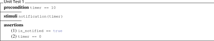
We neglect parts of the run \(\rho _1\) that describe how the environmental model service is activated and deactivated, respectively. We focus on the notification mechanism, i. e., the applicative part of the service. Activation and deactivation remain as requirements for the underlying middleware.
-
2.
Unit Test 2 and Unit Test 3 test the
 function. For both test cases, we again consider test preconditions, test stimuli, and assertions to be checked taking inputs from the corresponding runs. For the run \(\rho _2\), the mapping is given as follows:
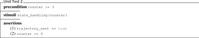
For the run \(\rho _3\), the mapping is given as follows:
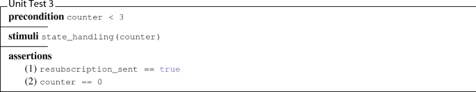
For the generated Unit Test 2 and Unit Test 3, we neglect parts of the runs \(\rho _2\) and \(\rho _3\) that describe how the trajectory planning is activated and deactivated, respectively. Similarly to the environmental model service, we focus only on the applicative and not the middleware parts.
 function. To do so, we consider test precondition, test stimulus, and two assertions to be checked by taking corresponding inputs from the run
 function. For both test cases, we again consider test preconditions, test stimuli, and assertions to be checked taking inputs from the corresponding runs. For the run

Finally, the generated tests (3) must be executed with a suitable test framework of choice or availability in order to obtain the test results (4). These two final steps complete the architecture development cycle sketched in Fig. 10.
3.7.3 Remarks on testing approach
Of course, the derived test cases do not cover the complete functionality of the corresponding software units. In this respect, test approaches that target criteria such as statement coverage, branch coverage, modified condition/decision coverage (MC/DC), or reinforced condition/decision coverage (RC/DC) are well-established. As an intention of the architecture development cycle, we see the possibility to derive test cases for software units resulting from system-level requirements at an early stage of development. These system-level requirements are rarely formalised today, which in turn is detrimental to the prospect of automating a fast-moving software development process.
4 Evaluation
In this section, we evaluate the approach presented. First, we outline in Sect. 4.1 how we intend to conduct the evaluation. Then, in Sect. 4.2, we detail the process of combining the tools used. Section 4.3 presents the initially platform-independent software/service architecture for automated driving according to level 4, which is then deployed to the centralised, novel computing platform in the following Sect. 4.4. The optimisation objectives also described in Sect. 3.3 are considered here. The deployment candidates obtained are analysed in more detail in two dedicated experiments:
-
Experiment 1 (cf. Sect. 4.5.1) explicitly analyses the end-to-end latency of the automated driving function. End-to-end latency covers the entire chain of the automated driving function, from the environment model to trajectory planning and control of the vehicle dynamics components. Experts set the maximum time to be 130 ms. Since this is a highly safety-critical function, there must be a redundant fail-operational execution path in case of e. g. a technical failure of the nominal execution path.
-
Experiment 2 (cf. Sect. 4.5.2) analyses the fail-operational behaviour. Of course, the strict end-to-end latency requirement (130 ms) applies, knowing that additional re-subscription must be performed at run-time. For the next step in the development, the transition to platform-specific software architecture (cf. Sect. 4.6), in our case, the AUTOSAR Adaptive Platform, must be made, which also includes validation employing tests.
In conclusion, we will put the evaluation results in the light of the guiding research question in Sect. 4.7. In the following, we evaluate our approach. The evaluation has three main objectives:
-
1.
The synthesis of service/client to core mappings that we call deployment candidates. These candidates are the result of a cross-domain deployment optimisation, which describes the integration of software from different automotive domains on a centralised computing platform and
-
2.
the assessment of timing properties for each deployment candidate that finally yield implementation candidates.
-
3.
In the remainder of Sect. 4, we demonstrate the process introduced in Sect. 3.7 to implement a selected deployment candidate.
4.1 Evaluation planning
In future automotive E/E architectures, software components that provide and consume services will play a major role. As in our example, a single or only a few multi-core ECUs will serve as a central computing platform that integrates software components from different domains. This will require software components that have different memory and performance design and security requirements to be brought together in a mixed-criticality environment. Of course, timely provision of all necessary services in such a safety-critical real-time system is also a necessity. It is these points that justify conducting the experiments with regard to the guiding research question.
We address this challenge in Sect. 4.4 and show how an optimised deployment using Pareto-optimisation built in the Z3 [12] SMT solver can be used to derive deployment candidates. We believe that the formulation of different constraints and optimisation objectives, which also contain mixed-integer linear constraints and complex logical relationships, can be formalised very well using SMT. Heuristic approaches would also be possible, but we found out that for our scenario, the found deployment candidates on common workstations are in the range of seconds or a few (less than 5) minutes and are therefore also useful for a real development project. The use of pure ILP or MILP solvers would be conceivable but would make the formulation of constraints and optimisation objectives massively more difficult (keywords: Big-M-method and formulation of nonlinear mixed-integer and disjunctive programming [38]).
In a second step of the so far platform-independent process, simulation-based latency simulations are carried out (cf. Sect. 4.5), which have to consider the requirements of the architecture and generally of a real-time system. Requirements were the use of SOME/IP with subscription and resubscription mechanisms in a switched Ethernet topology with Audio Video Bridging (AVB, IEEE 802.1 [42]) and credit-based traffic shaping (IEEE 802.1Qav [41]). Section 4.5 discusses the simulation-based solution considering the above-mentioned requirements. We conduct two experiments: The first experiment simulates only end-to-end latency for the nominal path. The second experiment simulates a reconfiguration at run-time, i. e., we want to investigate if a SOME/IP-based reconfiguration at run-time is possible or not using resubscription mechanisms. This is important to know because, for the fail-operational path, other network connections and ports on the Ethernet switch are used. Finally, we propose a transition from platform-independent to platform-specific software architectures by implementing the verified (platform-independent) deployment candidate using an AUTOSAR Adaptive software architecture, which is discussed in Sect. 4.6. Of course, we use the industry-standard AUTOSAR, especially the Adaptive Platform, which enables service-oriented communication and, thus, dynamics at run-time. The platform-independent model is refined to a platform-specific model by first specifying the service interfaces, which are then automatically translated into an .arxml (AUTOSAR XML) file. This, in turn, is used to generate header files that engineers must use to develop their implementation (.cpp files). In a model-based test step, the implementation is tested against the unit tests derived from the abstract behavioural specification.
To evaluate the approach, we use a platform-independent service-oriented software architecture for automated driving. Figure 11 depicts an export of the MBSE tool. The modelled hardware architecture and network topology are likewise depicted in Fig. 12. Details of processor, memory, and ASIL requirements and capabilities are explained in Sect. 4.4.

Simplified and platform-independent software architecture for automated driving

Network topology for automated driving with deployed software components from the platform-independent software architecture. The shown (yellow) software components are statically deployed. E. g. a camera software component is placed on the camera sensor. For the two environmental model instances, their target ECUs are known; however, their particular target core is part of the DSE process
In the following, the outlined evaluation is carried out. The evaluation may have several outcomes:
-
1.
We find that the tools and technologies used (SMT-based optimisation and simulation-based timing and network analysis) do not provide a solution for the modelled hardware topology and service architecture. The background is that different teams created the topology and resource requirements/service architecture, and there was no agreement.
Consequence: Revision of the topology and/or service architecture. If this is also unsuccessful, the approach can be considered a failure for the planned architecture and functionality.
-
2.
Deployment candidates may be found, but the time requirements cannot be met for them.
Consequence: Rework as in 1.
-
3.
At least one deployment candidate meets all time and bandwidth requirements and can also be implemented.
Consequence: The approach has been successfully evaluated for this topology and functionality.
4.2 Process steps
For the two main objectives of the evaluation, we consider the platform-independent model of a software architecture that is deployed and analysed with regard to timing. The interconnection of the tools PREEvision, the Z3 SMT solver, and the timing analysis tool chronSIM [44] is depicted in Fig. 13. PREEvision was originally developed in cooperation with Daimler AG and has since then been introduced to several OEMs and suppliers. For this reason, it offers a domain-specific modelling notation that is specially tailored to the requirements of the automotive industry. It meets all the concept development requirements of electric/electronic/software architectures in automotive engineering with plenty of graphical views. Since the industry partner’s toolchain includes PREEvision as a fundamental building block, we decided not to use other only UML-based MBSE tools for this paper.

Platform-independent process steps
We use PREEvision as (1) modelling environment for services and clients, their requirements with respect to hardware resources, and the computing platform. For the generation of deployment candidates, we (2) generate the DSE problem out of PREEvision and solve it using the Z3 SMT solver. Based on the explored deployment candidates, we then pursue a timing analysis for each candidate. Here, we again use PREEvision (3) in order to generate relevant inputs for a simulation-based timing analysis within chronSIM. We distinguish between two processes: first, the platform-independent process, which is depicted in Fig. 13 and results in a platform-independent software architecture discussed next. Second, the platform-specific process, which is depicted in Fig. 16 and discussed in Sect. 4.6.
4.3 Platform-independent software architecture
The guiding example of the evaluation is a simplified architecture for automated driving. As a first step within the platform-independent process, we introduce the corresponding software architecture that we have developed in PREEvision (see Fig. 11). The architecture consists of several components, each providing or consuming data. Services and clients are structured in a layered architecture, as we proposed in [54]. The lowest layer consists of services that sense the environment with the help of sensors like lidar, radar, or cameras and influence the vehicle’s movement with the help of actuators for steering and (de-)acceleration. Sensory information forms the database for the vehicle’s environmental model service, which is located on the second layer and is responsible for perception, sensor fusion, and scene understanding. As we can see, the driving dynamics service as the actuator coordination unit is also located on this layer. The environmental model service provides data for trajectory planning as a client on the top layer. On this basis, the trajectory planning calculates control requests that are finally translated by the driving dynamics service into lateral and longitudinal control actions, i. e., acceleration, braking, and steering. The architectural concept reflects automated driving at level 4, according to the SAE J3016 [88] classification. Level 4 says that the person sitting in the driver’s seat is not driving when the automated driving features are engaged. Moreover, the automated driving features will not require the driver to take over control. This is important since it influences the hardware as well as software architecture. In Fig. 12, such an architecture with all redundant computing as well as sensing capabilities is depicted. The driver is not part of any fail-operational path anymore. Examples can be local driverless taxis.
In addition to the services mentioned above and clients responsible for automated driving, we aim for the centralised consolidation of other software functions on the new platform’s computers. Since these software functions originate from other domains, we refer to this step as cross-domain optimisation. In total, we consider 25 services/clients from different domains: Infotainment (6), comfort (15), and assisted/automated driving (4). The environmental model service as one of the entities under consideration is deployed twice, a nominal and a fail-operational (FO) instance (see Sect. 3.2). Note that Fig. 12 also includes services for sensing and acting. Because their allocation to a particular physical device is fixed, they are not part of the design space exploration process.
Each service/client has a specific resource footprint in terms of (i) utilisation of the processor core, (ii) flash memory, (iii) volatile memory, and (iv) ASIL classification. Details are shown in Table 3. We cannot give the exact ASIL classification per service/client, processor core load, and memory consumption for confidentiality reasons, but we do give their assignment to classes. Using a single-core processor with a clock frequency of 200 MHz as a base, we specify the number of services/clients that require up to ten, up to 100 or more relative core usage. Similarly, three classes are specified for memory consumption and ASIL classification, with the numbers of the services/clients they contain. The ASIL requirements are necessary to select suitable processor cores that have specific ASIL qualifications. The appropriate levels of integrity are derived from a thorough evaluation by corporate safety experts. The environment model and trajectory planning (both instances) require the highest level (ASIL D), as they contribute significantly to a level 4 automated driving architecture. Of the remaining 22 services/clients, eight services/clients have assigned an ASIL B requirement, and 14 non-safety critical services/clients have assigned QM (quality management) requirements.
4.4 Computing platform and deployment
Figure 12 represents the centralised computing platform that is currently being evaluated as part of the development of a new overall E/E architecture. It consists of three ECUs equipped with different numbers of cores and hardware accelerators. Table 3 gives an overview of the specific characteristics of the ECUs. For reasons of confidentiality, we cannot give the ASIL classification per core, but only its absolute distribution over the ASIL levels: QM (3), A (0), B (15), C (0) and D (7). For the same reason, we cannot give the sizes of the predefined RAM partitions per core, but their rough distribution is given in the table again. The cores of an ECU share the available flash memory.
For the introduced and simplified architecture of an automated driving function (cf. Fig. 11), we take into account predefined service/client to ECU mappings within Fig. 12. These are the Environmental Model Service (ECU 1), the Environmental Model Service (FO) (ECU 3), the Trajectory Planning Client (ECU 2), the HD Map ServiceFootnote 5 (Telematics ECU), the Driving Dynamics Client (Driving Dynamics ECU), and all sensor and actuator services to their respective devices. ECU 1 and the connected sensors are part of the nominal execution path, while ECU 3 and the connected fail-operational sensors form the fail-operational path. The LIN gateway is not part of the design space exploration analysis but is considered during network simulations since it produces bus load at the Ethernet switch.
Optimisation The DSE process is automated by encoding the deployment problem into an SMT instance. For this purpose, the performance, memory, and safety requirements are formulated as constraints, and the two optimisation objectives mentioned in Sect. 3.3 form the objectives that must be minimised at the same time:
-
(1)
First, we want to minimise the number of cores used;
-
(2)
Second, we want to prevent non-safety-critical software components from being used on cores with high ASIL qualification.
Additional cores can be removed to save money and energy, which in many cases is a decisive factor in the automotive sector. The second optimisation function ensures the efficient utilisation of the highly qualified processor cores. Usually, those cores are expensive and thus reserved for services that require e. g. an ASIL D qualification. We achieve this by identifying services/clients using processor cores that overfulfil posed ASIL requirements as violations. The subsequent evaluation of violations is done by penalty values (cf. Sect. 3.3).

Pareto-front of the three found Pareto-optimal architecture candidates. For each candidate, timing characteristics is analysed in the next step. Note, the dashed line only illustrates the Pareto front where alternative—similarly good—solutions could lie
Results We use the Z3 SMT solver supporting Pareto-optimisation. Figure 14 shows the Pareto-front with three computed deployment candidates indicated as circles (the solver did not find other Pareto-optimal solutions). The areas between deployment candidates 1 and 2 or 1 and 3 are not shown in detail (the dashed line). Further, non-dominated candidates could still lie here. No further Pareto-optimal solutions can lie in the red-shaded area since they are definitively dominated by the ones already found. Recall that in the min–min optimisation problem presented here (minimise the number of used processor cores, minimise the penalties), the solutions always strive towards the “lower left”. We speak here of deployment candidates because in the next step—the temporal and bandwidth simulation (cf. Sect. 4.5)—it is checked for each of these candidates whether both the temporal requirements are met and the utilisation of the involved buses is within the bounds. For this purpose, the links at the switch are also taken into account in the simulation. Each solution describes a mapping of software applications (clients and services) to processor cores. These different mappings yield different network configurations as data is transmitted depending on the deployment.
The x-axis shows the number of processor cores. The y-axis shows the summed up penalties. Recall that we want to minimise both values.
As the DSE process’s output, each of the three deployment candidates is characterised by service/client to core mappings. From these mappings, we subsequently derive the service/client to ECU mappings and provide them in Table 4.
As the table shows, the ECUs as deployment targets of certain services/clients can change depending on the considered candidate. For the Ethernet communication network, these changes have an impact on the load that is carried by the different links since services/clients share communication dependencies among each other. We, therefore, provide an overview of necessary data transmission rates per Ethernet link for each of the three candidates. Note, the allocation of these transmission rates is only done at run-time since we consider a dynamic communication paradigm in the form of service-orientation. Table 5 shows the simulation results of the different network configurations. Each configuration corresponds to that of a deployment candidate.
As part of our network configurations, communication is based on switched Ethernet using the Audio Video Bridging (AVB) standard. Traffic is shaped using the credit-based shaping algorithm.
The feasibility of the approach—at least for the considered architecture size—has been shown. This answers the guiding research question by demonstrating the applicability for an actual pre-development project taken from the industry. In this setting, a new centralised computing platform consolidates existing software applications from different automotive domains and a highly innovative level 4 automotive driving function modelled in a service-oriented design paradigm.
4.5 Simulation
Depending on the services’ distribution and their relationship to each other (i. e., service-client-relationship), different transfer rates are determined for each configuration. During the simulation, we perform timing analyses for all three candidates of the automated driving architecture (cf. Fig. 12). Our goal is to assess the end-to-end latency from the vehicle environment’s perception to the vehicle dynamics’ stimulation.
4.5.1 Experiment 1
Description The first simulation uses only a single environment model without the possibility of fail-over to the redundant instance. We are interested in an end-to-end latency evaluation of the network paths. Figure 15a shows the network path extending from ECU 1, the Ethernet switch, to ECU 2, and ECU 4. The different application to processor core mappings for the three deployment candidates are depicted in Table 4. In addition, the resulting network load on the respective communication links is shown in Table 5. The simulation is performed for each candidate individually.
Starting from the assumption that the trajectory planning as a client has already subscribed to the service of the environment model, the behaviour of the network path can be described as follows: The environment model periodically provides event-based notifications via the Ethernet switch to ECU 2. The trajectory planning then waits until the third event is received and then stimulates the vehicle dynamics, which is used on ECU 4 on the basis of a CAN message. As a requirement, we have set up an end-to-end latency of 130 ms.

a Nominal network path and b fail-operational path for the automated driving architecture
For the first experiment, we simulate the deployed architecture (cf. Fig. 12) without the possibility to reconfigure the system in case of a timing violation and to switch to the fail-operational instance of the environment model. Therefore, we will only focus on the communication path shown in Fig. 15a. By varying the jitter of 1 s for the start time of the publish/subscribe process (cf. Fig. 2) between the environmental model and trajectory planning function, diversity is introduced into the simulation runs.
Results We conducted 500 simulation runs for each of the three deployment candidates and thus derived network configurations. The question is how we got to 500 runs. During the simulation, randomness plays a role, as the jitter is also varied. With only a few simulation runs, important timing behaviours may not be detected. If we choose a huge number, there will, of course, be repetitions, which should also be avoided because they do not provide any further knowledge and only cost time. So we slowly approached the 500 in exchange with experts until there were no more new behaviours and the first repetitions were identified. From this, we deduced that all candidates met the time requirement of 130 ms in 500 runs.
4.5.2 Experiment 2
Description The second simulation examines a reconfiguration at run-time to activate the fail-operational path. The behaviour of the network path in Fig. 15b can be described as follows: First, the trajectory planner sends the subscription message as the client of the fail-operational environmental model. This subscription message is triggered by the Reconfiguration EventFootnote 6 and activates the environmental model service, which periodically delivers notifications. The trajectory planning, in turn, monitors whether the timing property of the environmental model, the receipt of at least three events within a period of 30 ms, holds. If no violation is detected, the driving dynamics’ stimulation is performed based on the corresponding CAN message.
We now introduce the fail-operational instance of the environmental model allowing a system reconfiguration at run-time. To enforce the environmental model’s reconfiguration process within the simulations, we make sure that the nominal instance does not provide its service in time. We do this by scheduling an additional application on the corresponding core. This application has a higher priority than the environmental model and delays its execution. As a result, the nominal instance’s timing property for the environmental model becomes violated, and the trajectory planning initialises the reconfiguration process as a client.
However, this also creates additional latency because of executing the publish/subscribe process again. We take this into account by defining a timing requirement on the maximal reconfiguration time with the help of safety experts, which is 130 ms. Whenever the time from the reconfiguration event until the driving dynamics’ stimulation exceeds 130 ms, we will note this as a failed simulation run.
Results Again, we conducted 500 simulation runs for each of the three architecture candidates. As a result, we could derive that all candidates met the posed timing requirement of 130 ms even when a run-time reconfiguration between the nominal and the fail-operational instance of the environmental model service occurs.
Besides different network configurations, we introduced variation potential among the simulations by introducing a jitter of 1 s for the publish-subscribe process between the environmental model and the trajectory planning client.
4.5.3 Overall simulation results
The results are based on the first drafts of software functions. We again need to support the corresponding network analysis by virtual validation techniques for the ongoing and more detailed design of these functions. Nevertheless, from the already gained simulation results, we derive two important insights: (1) All architecture candidates meet posed timing requirements for the simulation experiments. (2) The simulation of candidate 1 showed the lowest number of reconfigurations.
Since the messages—exchanged during run-time reconfiguration—put additional load on the network and might conflict with an increasing network configuration in further development, we treat this candidate with special attention.
The thoroughly conducted experiments show that a platform-independent model with timing requirements and hardware capabilities annotated can indeed be used to evaluate the timing behaviour. In a simulation-based approach, it could be demonstrated that all requirements for temporal behaviour could be fulfilled. For this purpose, the practicability was demonstrated by means of a model-to-text transformation and the connection of a suitable tool.
4.6 Platform-specific software architecture
We receive candidates that have been validated by simulations and are now considered for implementation. Since the candidates are modelled in a platform-independent manner, we first need to map them to platform-specific software components—according to AUTOSAR Adaptive—as exemplified in Fig. 7. For the rest of the software component implementation process, we focus on the process steps specified in Fig. 16.

Platform-specific process steps
The platform-specific process describes two parallel activities that merge in the test execution step:
-
1.
The first branch models service interfaces and implements them as software units (depicted with solid lines, left path);
-
2.
The second branch models the abstract behaviour of software components in order to generate test cases (depicted in dashed lines, right path).
Each of those activities is described next.
4.6.1 Service interface design
Following the mapping to AUTOSAR software components, the service interfaces of the software functions to be implemented are described. In Fig. 17, the environmental model service interface is illustrated as composition of six functions:


Service interface provided by environmental model software component as modelled within the MSBE tool
The function  triggers the middleware to transmit objects to the client describing the vehicle’s environment. This function has no parameters, takes objects located in one shared memory accessible by the middleware, and finally stimulates the Ethernet controller for transmission. All other functions have either typed input or output parameters.
4.6.2 Implementation
All six functions shown in the service interface depicted above need to be part of the implementation of the environmental model service interface. To do so, we generate the AUTOSAR XML representation of the service interface. Listing 3 shows the function  as part of the ARXML representation of the environmental model service interface (environmentalModel.arxml).

It contains for each function its signature, which is used to generate a corresponding C++ header file. This header file is, in our case, provided to developers of the automated driving department. For its implementation, a detailed behavioural model is used to generate the application’s source code. As our approach is aimed at level 4 of automated driving, this model and thus the implementation of the header file is still under development. As an exemplary implementation of the environmental model service interface, Listing 1 is given.
4.6.3 Abstract behavioural model design
Now, we consider the second, right branch of the depicted process in Fig. 16. Here, we aim to generate test cases from abstract behavioural models given as UML state machines. For the environmental model software component, we use the state machine given in Fig. 8. This abstract behavioural model—developed by system architects—shares the commonality with the detailed behavioural model—currently under development—that both refer to the same service interface in terms of structure (parameters and data types). However, concerning behaviour, both models are developed independently. They, therefore, provide redundancy required for model-based testing: One model for generating test cases and one for generating the application’s source code.
4.6.4 Test case generation
In Sect. 3.7.2, we illustrated the concept of generating test cases from runs through a state machine. Now, we realise this concept by deriving test case descriptions from UML state machine diagrams. These descriptions are formalised within an in-house DSL and thus abstract from target languages. As an example, we provide TestCase1 (cf. Sect. 3.7.2) as an abstract test case description within the in-house DSL in Listing 4.

To achieve an executable test case, we use an Xtend-based generator that outputs C++ unit test cases taking abstract test descriptions as input. The example given in Listing 5 depicts the software unit test case derived from the abstract test case description in Listing 4.

The software unit test case is in line with the Google Test framework. Note, for this test case, we refer to the exemplary implementation of the header file environmentalModel.h in Listing 1.
4.6.5 Test execution
The execution of the test case in Listing 5 conducts in principle the following steps: First, we stimulate the environmental model service interface by the function call  . Afterwards, two assertions are checked and logged within the test report. This report is finally provided to architects as feedback.
The abstract interface models of the platform-independent software architecture are refined by modelling a precise platform-specific correspondence. Besides this interface refinement, i. e., concretisation by increasing the level of detail, the abstract behaviour-describing models are also refined by the actual implementation. This can be done with MBSE tools such as Simulink or ASCET or can be implemented manually. The generated test cases must be created from a different (abstract model) than the actual implementation, for example. Both the interface specification and the implementation follow the guidelines and specifications of the AUTOSAR Adaptive Platform.
4.7 Overall evaluation result
In conclusion, the evaluation can be assessed as follows. In the guiding research question and the accompanying three framework conditions, we asked whether it is possible in a pre-development project to design an equally novel centralised architecture for automated driving according to level 4 for a highly innovative function in such a way that it can be fed into a further implementation process. The experiments and observations that have now been carried out showed that both the framework conditions could be fulfilled, and the downstream development process could be demonstrated. Of the three possible evaluation results outlined in Sect. 4.1, the third case, i. e., the positive evaluation of the approach presented here, could be confirmed.
5 Discussion
For the discussion, we account assumptions and limitations that are embedded in our approach and evaluation.
5.1 Assumptions
Our approach assumes a component-based model of a service-oriented architecture embedded into an overall automotive E/E architecture model also respecting hardware. In addition, we assume to have fine-grained hardware resource requirements at an early stage of development. Both assumptions are not unrealistic but depend on a strong collaboration between E/E architects, software architects, and function developers beyond one company’s border.
5.2 Limitations
We considered 25 software functions from the automotive domains infotainment, comfort, and assisted/automated driving for software deployment within a centralised computing platform. As a supplement for future work, we want to scale these figures in two ways: On the one hand, we want to increase the number of software functions from the domains already considered. On the other hand, we want to account for functions from domains not yet considered, such as driving dynamics. Another limitation is the evaluation example. Here, we considered a reconfiguration for the environmental model based on two service instances and not an overall fail-operational concept. To achieve this, all components of an automated driving architecture need to have fail-operational capabilities. In terms of the timing assessment, the applied method is simulation-based and does not provide theoretical worst-case considerations. Finally, the exemplified process in Sect. 4.6 lacks in conducting the test execution step. As already mentioned, this is true since software for an architecture featuring level 4 of driving automation is not present yet.
6 Conclusion
Service-oriented architectures promote a better run-time decoupling between software and hardware than currently dominant signal-oriented architectures. Also, design-time activities can be eased since network communication dependencies between distributed software applications do not need to be predefined (cf. Fig. 1b). For accomplishing the rollout of this new architectural style at scale, we addressed three main challenges and provided possible solutions as contributions.
6.1 Addressed challenges
Challenge 1 – Deployment (C1) The continuing trend towards centralised computer platforms offers opportunities to unify software applications from different automotive domains. As a result of this trend, the degree of distribution, which currently comprises around 100 ECUs, can be reduced. In this paper, we have merged the deployment problem of service-oriented architectures with the idea of centralised computing. The central elements of this merging are: (1) Models of service-oriented architectures fostering logical and deployment aspects, (2) synthesis of architecture candidates that are optimal according to efficient utilisation of computing resources, and (3) run time assessments of architecture candidates in a simulation-based manner.
Challenge 2 – Assessment of Timing Properties (C2) Especially for the last element of the above, we dealt with the idea of reconfiguration at run-time, which is not available in current architectures. We presented an approach for evaluating timing requirements with special emphasis on reconfiguration at run-time. For this purpose, an engineer does not have to bind a fail-over service statically because service discovery and binding used at run-time are also part of the simulation model. One of the main advantages of the simulation-based approach compared to worst-case estimation methods is that they are far less pessimistic or conservative and waste fewer resources. The relevant standard ISO 26262 does not impose any requirements in this respect.
Challenge 3 – Transition From PIM to PSM (C3) The provision of abstraction between software and hardware—native for service-oriented architectures—can accelerate automotive software development. Similar work in this respect is rare (cf. Sect. 2.2.3). We tackled the corresponding field by focusing on two important parts: (1) The mapping relation between flexible platform-independent models of service-oriented architectures onto platform-specific ones and (2) the idea of an architecture development cycle that synchronises architects and software engineers by test cases as shared artefacts that are fed back.
6.2 Future perspective
For the rollout of our approach and service-oriented architectures in general, the introduction of IP-based communication networks on a large scale is a necessary prerequisite. As a possible blueprint, we consider the topology given in Fig. 6a. Besides the technical infrastructure available in parts, the corresponding development processes and development methodologies are still open issues. The following points must be considered in future work: (1) The application and evaluation of our architecture design approach within an overall vehicle development process, (2) the strengthening of feedback loops between architects and software engineers to cope with incremental development rarely applied today, (3) the consequencing challenge to handle versions and variants on the model and source code level, and (4) the extension of automotive service-oriented architectures to the potentially non-automotive software ecosystem.
For all of these challenges, stakeholders will have an intrinsic desire for problem reduction and abstraction. As model-based techniques strongly account for these needs, we will foster their development and usage at the BMW Group.
Notes
See §4.1.4.6 of the SOME/IP protocol specification: https://www.autosar.org/fileadmin/user_upload/standards/foundation/1-0/AUTOSAR_PRS_SOMEIPProtocol.pdf
In Fig. 6a, we consider a single gateway connecting the central computing platform to a LIN (Local Interconnect Network) network that implements sensors and actuators relevant to the comfort functions.
A software component type can be used to instantiate software components several times.
The HD Map service is not part of the fail-operational driving mode.
This event indicates that within a period of \(\varDelta =30\) ms, the trajectory planning has received less than three events.
References
Aleti, A., Bjornander, S., Grunske, L., Meedeniya, I.: Archeopterix: An extendable tool for architecture optimization of aadl models. In: Proceedings of the ICSE Workshop on Model-based Methodologies for Pervasive and Embedded Software, vol. 0, pp. 61–71. IEEE Computer Society, Los Alamitos, CA, USA (2009). https://doi.org/10.1109/MOMPES.2009.5069138
Aleti, A., Buhnova, B., Grunske, L., Koziolek, A., Meedeniya, I.: Software architecture optimization methods: A systematic literature review. IEEE Trans. Software Eng. 39(5), 658–683 (2013). https://doi.org/10.1109/TSE.2012.64
Alliance, G.: GENIVI. https://www.genivi.org/. Accessed: 2020-02-11
Alur, R., Dill, D.L.: A theory of timed automata. Theor. Comput. Sci. 126(2), 183–235 (1994). https://doi.org/10.1016/0304-3975(94)90010-8
Amdahl, G.M.: Validity of the single processor approach to achieving large scale computing capabilities. In: Proceedings of the April 18–20, 1967, spring joint computer conference, pp. 483–485. Association for Computing Machinery (1967). https://doi.org/10.1145/1465482.1465560
Arunkumar, N., Karunamoorthy, L.: An optimization technique for vendor selection with quantity discounts using genetic algorithm. J. Ind. Eng. Int. Islamic Azad University, South Teheran Branch (2007). http://www.sid.ir/En/VEWSSID/J_pdf/117320070401.pdf. [Online; accessed 25-August-2020]
AUTOSAR: Automotive Open System Architecture. http://www.autosar.org
Axelsson, J.: Cost models for electronic architecture trade studies. In: 6th International Conference on Engineering of Complex Computer Systems (ICECCS 2000), 11–15 September 2000, Tokyo, Japan, p. 229. IEEE Computer Society (2000). https://doi.org/10.1109/ICECCS.2000.10004
Axelsson, J.: Cost models with explicit uncertainties for electronic architecture trade-off and risk analysis. In: Proceedings of 16th International Symposium of the International Council on Systems Engineering (2006). http://www.mrtc.mdh.se/index.php?choice=publications&id=1155
Becker, S., Koziolek, H., Reussner, R.H.: The palladio component model for model-driven performance prediction. J. Syst. Softw. 82(1), 3–22 (2009). https://doi.org/10.1016/j.jss.2008.03.066
Bengtsson, J., Larsen, K.G., Larsson, F., Pettersson, P., Yi, W.: UPPAAL - a tool suite for automatic verification of real-time systems. In: R. Alur, T.A. Henzinger, E.D. Sontag (eds.) Hybrid Systems III: Verification and Control, Proceedings of the DIMACS/SYCON Workshop on Verification and Control of Hybrid Systems, October 22-25, 1995, Ruttgers University, New Brunswick, NJ, USA, Lecture Notes in Computer Science, vol. 1066, pp. 232–243. Springer (1995). https://doi.org/10.1007/BFb0020949
Bjørner, N., Phan, A.D.: \(\nu \)Z - Maximal Satisfaction with Z3. In: T. Kutsia, A. Voronkov (eds.) SCSS 2014, EPiC Series, 30, 1–9 (2014)
Bocchi, L., Fiadeiro, J.L., Lopes, A.: Service-oriented modelling of automotive systems. In: 2008 32nd Annual IEEE International Computer Software and Applications Conference, pp. 1059–1064 (2008). https://doi.org/10.1109/COMPSAC.2008.228
Bosch, J. (ed.): Continuous Software Engineering. Springer (2014). https://doi.org/10.1007/978-3-319-11283-1
Broy, M., Gleirscher, M., Kluge, P., Krenzer, W., Merenda, S., Wild, D.: Automotive architecture framework: Towards a holistic and standardised system architecture description. Tech. rep., Technische Universität München (2009). ftp://ftp.software.ibm.com/software/plm/resources/AAF_TUM_TRI0915.pdf
Broy, M., Krüger, I.H., Meisinger, M.: A formal model of services. ACM Trans. Softw. Eng. Methodol. 16(1) (2007). https://doi.org/10.1145/1189748.1189753
Broy, M., Stølen, K.: Specification and development of interactive systems: FOCUS on streams, interfaces, and refinement. Springer-Verlag, New York (2001)
Bucher, H., Kamm, S., Becker, J.: Cross-layer behavioral modeling and simulation of e/e-architectures using preevision and ptolemy II. Simul. Notes Eur. 29(2), 73–78 (2019). https://doi.org/10.11128/sne.29.tn.10472
Carnegie Mellon University: Open Source AADL Tool Environment (2020 (accessed August 25, 2020)). https://osate.org
Cebotari, V., Kugele, S.: On the nature of automotive service architectures. In: IEEE International Conference on Software Architecture Companion, ICSA Companion 2019, Hamburg, Germany, March 25-26, 2019, pp. 53–60. IEEE (2019). https://doi.org/10.1109/ICSA-C.2019.00017
chronval. https://www.inchron.com/tool-suite/chronval.html. Accessed: 2019-01-16
Dajsuren, Y.: On the design of an architecture framework and quality evaluation for automotive software systems. Dissertation, Technische Universiteit Eindhoven, Eindhoven (2015). https://pure.tue.nl/ws/files/15934981/20160307_Dajsuren.pdf
Damm, W., Votintseva, A., Metzner, A., Josko, B., Peikenkamp, T., Böde, E.: Boosting re–use of embedded automotive applications through rich components. In: FIT 2005—Foundations of Interface Technologies (2005)
Daniel J.G.: Ein modellbasiertes, graphisch notiertes, integriertes Verfahren zur Bewertung und zum Vergleich von Elektrik/Elektronik-Architekturen. Dissertation, Karlsruher Insitut für Technologie, Karlsruhe (2016). https://publikationen.bibliothek.kit.edu/1000062484
Dziwok, S., Pohlmann, U., Piskachev, G., Schubert, D., Thiele, S., Gerking, C.: The mechatronicuml design method: Process and language for platform-independent modeling. Tech. Rep. tr-ri-16-352, Software Engineering Department, Fraunhofer IEM / Software Engineering Group, Heinz Nixdorf Institute, Zukunftsmeile 1, 33102 Paderborn, Germany (2016). Version 1.0
EAST-ADL domain model specification (2013). http://www.east-adl.info/Specification/V2.1.12/EAST-ADL-Specification_V2.1.12.pdf
Eclipse Foundation: Franca IDL. https://github.com/franca/franca. Accessed: 2020-02-12
Ernst, R., Kuntz, S., Quinton, S., Simons, M.: The logical execution time paradigm: New perspectives for multicore systems (dagstuhl seminar 18092). Dagstuhl Rep. 8, 122–149 (2018)
ETAS: ASCET-DEVELOPER. https://www.etas.com/de/portfolio/ascet-developer.php. Accessed: 2020-02-11
Feiler, P., Gluch, D., Hudak, J.: The architecture analysis & design language (AADL): An introduction. Tech. Rep. CMU/SEI-2006-TN-011, Software Engineering Institute, Carnegie Mellon University, Pittsburgh, PA (2006). http://resources.sei.cmu.edu/library/asset-view.cfm?AssetID=7879
Fellini, R., Michelena, N., Papalambros, P., Sasena, M.: Optimal design of automotive hybrid powertrain systems. In: Environmentally Conscious Design and Inverse Manufacturing, 1999. Proceedings. EcoDesign ’99: First International Symposium On, pp. 400–405 (1999). https://doi.org/10.1109/ECODIM.1999.747645
Ferdinand, C., Heckmann, R., Langenbach, M., Martin, F., Schmidt, M., Theiling, H., Thesing, S., Wilhelm, R.: Reliable and precise WCET determination for a real-life processor. In: T.A. Henzinger, C.M. Kirsch (eds.) Embedded Software, First International Workshop, EMSOFT 2001, Tahoe City, CA, USA, October, 8-10, 2001, Proceedings, Lecture Notes in Computer Science, vol. 2211, pp. 469–485. Springer (2001). https://doi.org/10.1007/3-540-45449-7_32
Florentz, B., Huhn, M.: Embedded systems architecture: Evaluation and analysis. In: C. Hofmeister, I. Crnkovic, R.H. Reussner (eds.) Quality of Software Architectures, Second International Conference on Quality of Software Architectures, QoSA 2006, Västerås, Sweden, June 27-29, 2006 Revised Papers, Lecture Notes in Computer Science, vol. 4214, pp. 145–162. Springer (2006). https://doi.org/10.1007/11921998_14
fortiss GmbH: Welcome to the fortiss AutoFOCUS 3 (2018). https://af3-developer.fortiss.org/
Geiger, A., Lenz, P., Urtasun, R.: Are we ready for autonomous driving? the KITTI vision benchmark suite. In: 2012 IEEE Conference on Computer Vision and Pattern Recognition, Providence, RI, USA, June 16-21, 2012, pp. 3354–3361. IEEE Computer Society (2012). https://doi.org/10.1109/CVPR.2012.6248074
Glaß, M., Lukasiewycz, M., Wanka, R., Haubelt, C., Teich, J.: Multi-objective routing and topology optimization in networked embedded systems. In: W.A. Najjar, H. Blume (eds.) Proceedings of the 2008 International Conference on Embedded Computer Systems: Architectures, Modeling and Simulation (IC-SAMOS 2008), Samos, Greece, July 21-24, 2008, pp. 74–81. IEEE (2008). https://doi.org/10.1109/ICSAMOS.2008.4664849
Google: Android Auto. https://www.android.com/auto/. Accessed: 2020-02-11
Grossmann, I.E.: Review of nonlinear mixed-integer and disjunctive programming techniques. Optim. Eng. 3(3), 227–252 (2002)
Grunske, L., Lindsay, P.A., Bondarev, E., Papadopoulos, Y., Parker, D.: An outline of an architecture-based method for optimizing dependability attributes of software-intensive systems. In: R. de Lemos, C. Gacek, A.B. Romanovsky (eds.) Architecting Dependable Systems IV [the book is a result of the ICSE 2006 and DSN 2006 workshops], Lecture Notes in Computer Science, vol. 4615, pp. 188–209. Springer (2006). https://doi.org/10.1007/978-3-540-74035-3_9
Haberl, W., Herrmannsdoerfer, M., Kugele, S., Tautschnig, M., Wechs, M.: Seamless model-driven development put into practice. In: T. Margaria, B. Steffen (eds.) Leveraging Applications of Formal Methods, Verification, and Validation - 4th International Symposium on Leveraging Applications, ISoLA 2010, Heraklion, Crete, Greece, October 18-21, 2010, Proceedings, Part I, Lecture Notes in Computer Science, vol. 6415, pp. 18–32. Springer (2010). https://doi.org/10.1007/978-3-642-16558-0_4
IEEE standard for local and metropolitan area networks - virtual bridged local area networks amendment 12: Forwarding and queuing enhancements for time-sensitive streams. Tech. rep. (2010). https://doi.org/10.1109/IEEESTD.2009.5375704
IEEE standard for local and metropolitan area networks–audio video bridging (AVB) systems. Tech. rep. (2011). https://doi.org/10.1109/IEEESTD.2011.6032690
IEEE Std 1666-2011 (Revision of IEEE Std 1666-2005): IEEE Standard for Standard SystemC Language Reference Manual. IEEE (2012). https://books.google.de/books?id=shlZAQAACAAJ
Inchron: chronSIM. https://www.inchron.com/tool-suite/chronsim.html. Accessed: 2019-01-16
ISO/IEC/IEEE Systems and software engineering – Architecture description. ISO/IEC/IEEE 42010:2011(E) (Revision of ISO/IEC 42010:2007 and IEEE Std 1471-2000) pp. 1–46 (2011). https://doi.org/10.1109/IEEESTD.2011.6129467
ISO: Road vehicles–Functional safety (ISO 26262) (2011)
Jaensch, M.: Modulorientiertes Produktlinien Engineering für den modellbasierten Elektrik/Elektronik-Architekturentwurf. Karlsruher Institut für Technologie (2014). https://books.google.de/books?id=mhT1pN4Xg3UC
Kampmann, A., Alrifaee, B., Kohout, M., Wüstenberg, A., Woopen, T., Nolte, M., Eckstein, L., Kowalewski, S.: A dynamic service-oriented software architecture for highly automated vehicles. In: 2019 IEEE Intelligent Transportation Systems Conference, ITSC 2019, Auckland, New Zealand, October 27–30, 2019, pp. 2101–2108. IEEE (2019). https://doi.org/10.1109/ITSC.2019.8916841
Kugele, S., Cebotari, V., Gleirscher, M., Farzaneh, M.H., Segler, C., Shafaei, S., Vögel, H.J., Bauer, F., Knoll, A., Marmsoler, D., Michel, H.U.: Research challenges for a future-proof e/e architecture—a project statement. In: 15. Workshop Automotive Software Engineering, Proceedings, Chemnitz, Germany. LNI (2017)
Kugele, S., Haberl, W., Tautschnig, M., Wechs, M.: Optimizing automatic deployment using non-functional requirement annotations. In: ISoLA, pp. 400–414 (2008)
Kugele, S., Hettler, D., Peter, J.: Data-centric communication and containerization for future automotive software architectures. In: IEEE International Conference on Software Architecture, ICSA 2018, Seattle, WA, USA, April 30 - May 4, 2018, pp. 65–74. IEEE Computer Society (2018). https://doi.org/10.1109/ICSA.2018.00016
Kugele, S., Hettler, D., Shafaei, S.: Elastic service provision for intelligent vehicle functions. In: W. Zhang, A.M. Bayen, J.J.S. Medina, M.J. Barth (eds.) 21st International Conference on Intelligent Transportation Systems, ITSC 2018, Maui, HI, USA, November 4-7, 2018, pp. 3183–3190. IEEE (2018). https://doi.org/10.1109/ITSC.2018.8569374
Kugele, S., Marmsoler, D., Mata, N., Werther, K.: Verification of component architectures using mode-based contracts. In: 2016 ACM/IEEE International Conference on Formal Methods and Models for System Design, MEMOCODE 2016, Kanpur, India, November 18-20, 2016, pp. 133–142 (2016). https://doi.org/10.1109/MEMCOD.2016.7797758
Kugele, S., Obergfell, P., Broy, M., Creighton, O., Traub, M., Hopfensitz, W.: On service-orientation for automotive software. In: 2017 IEEE International Conference on Software Architecture, ICSA 2017, Gothenburg, Sweden, April 3-7, 2017, pp. 193–202. IEEE (2017). https://doi.org/10.1109/ICSA.2017.20
Kugele, S., Pucea, G., Popa, R., Dieudonné, L., Eckardt, H.: On the deployment problem of embedded systems. In: 13. ACM/IEEE International Conference on Formal Methods and Models for Codesign, MEMOCODE 2015, Austin, TX, USA, September 21–23, 2015, pp. 158–167. IEEE (2015). https://doi.org/10.1109/MEMCOD.2015.7340482
Kugele, S., Pucea, G.: Model-based optimization of automotive e/e-architectures. In: V. Ganesh, N. Williams (eds.) Proceedings of the 6th International Workshop on Constraints in Software Testing, Verification, and Analysis, CSTVA 2014, Hyderabad, India, May 31, 2014, pp. 18–29. ACM (2014). https://doi.org/10.1145/2593735.2593739
Kumar, R., Izui, K., Masataka, M., Nishiwaki, S.: Multilevel redundancy allocation optimization using hierarchical genetic algorithm. IEEE Trans. Reliab. 57(4), 650–661 (2008). https://doi.org/10.1109/TR.2008.2006079
Lampe, B., Woopen, T., Eckstein, L.: Collective Driving—Cloud Services for Automated Vehicles in UNICARagil. In: 28th Aachen Colloquium. Aachen, Germany (2019)
Lee, E.A., Neuendorffer, S., Wirthlin, M.J.: Actor-oriented design of embedded hardware and software systems. J. Circ. Syst. Comput. 12(3), 231–260 (2003). https://doi.org/10.1142/S0218126603000751
Lohstroh, M., Romero, Í.Í., Goens, A., Derler, P., Castrillon, J., Lee, E.A., Sangiovanni-Vincentelli, A.: Reactors: A deterministic model for composable reactive systems. In: Proceedings of the 9th Workshop on Design, Modeling and Evaluation of Cyber Physical Systems (CyPhy 2019) and the Workshop on Embedded and Cyber-Physical Systems Education (WESE 2019), p. 26pp (2019)
Lotz, J., Vogelsang, A., Benderius, O., Berger, C.: Microservice architectures for advanced driver assistance systems: A case-study. In: IEEE International Conference on Software Architecture Companion, ICSA Companion 2019, pp. 45–52. IEEE (2019). https://doi.org/10.1109/ICSA-C.2019.00016
Lukasiewycz, M., Glaß, M., Haubelt, C., Teich, J., Regler, R., Lang, B.: Concurrent topology and routing optimization in automotive network integration. In: L. Fix (ed.) Proceedings of the 45th Design Automation Conference, DAC 2008, Anaheim, CA, USA, June 8-13, 2008, pp. 626–629. ACM (2008). https://doi.org/10.1145/1391469.1391629
Malkis, A., Marmsoler, D.: A model of service-oriented architectures. In: 2015 IX Brazilian Symposium on Components, Architectures and Reuse Software, SBCARS 2015, Belo Horizonte, Minas Gerais, Brazil, September 21–22, 2015, pp. 110–119. IEEE Computer Society (2015). https://doi.org/10.1109/SBCARS.2015.22
Martens, A., Koziolek, H.: Automatic, model-based software performance improvement for component-based software designs. Electron. Notes Theor. Comput. Sci. 253(1), 77–93 (2009). https://doi.org/10.1016/j.entcs.2009.09.029
MATLAB: version 7.10.0 (R2010a). The MathWorks Inc., Natick, Massachusetts (2010)
Meedeniya, I., Buhnova, B., Aleti, A., Grunske, L.: Reliability-driven deployment optimization for embedded systems. J. Syst. Softw. 84(5), 835–846 (2011). https://doi.org/10.1016/j.jss.2011.01.004
Menard, C., Goens, A., Lohstroh, M., Castrillón, J.: Achieving determinism in adaptive AUTOSAR. CoRR abs/1912.01367 (2019). arXiv:1912.01367
Modelica Association Project “FMI”: Functional Mock-up Interface for Model Exchange and Co-Simulation (2014)
Obergfell, P., Kugele, S., Sax, E.: Model-based resource analysis and synthesis of service-oriented automotive software architectures. In: M. Kessentini, T. Yue, A. Pretschner, S. Voss, L. Burgueño (eds.) 22nd ACM/IEEE International Conference on Model Driven Engineering Languages and Systems, MODELS 2019, Munich, Germany, September 15–20, 2019, pp. 128–138. IEEE (2019). https://doi.org/10.1109/MODELS.2019.000-8
Obergfell, P., Kugele, S., Segler, C., Knoll, A., Sax, E.: Continuous software engineering of innovative automotive functions: An industrial perspective. In: IEEE International Conference on Software Architecture Companion, ICSA Companion 2019, Hamburg, Germany, March 25–26, 2019, pp. 127–128. IEEE (2019). https://doi.org/10.1109/ICSA-C.2019.00030
OMG: Data Distribution Service (DDS), 1.4 edn. (2015). http://www.omg.org/spec/DDS/1.4/
OMG: Meta object facility (2016). http://www.omg.org/spec/MOF/
OMG: UML Profile for MARTE: Modeling and Analysis of Real-Time Embedded Systems (2009)
Pelliccione, P., Knauss, E., Heldal, R., Ågren, M., Mallozzi, P., Alminger, A., Borgentun, D.: Automotive architecture framework: The experience of Volvo Cars. J. Syst. Archit. 77 (2017). https://doi.org/10.1016/j.sysarc.2017.02.005
Pohl, K., Broy, M., Daembkes, H., Hnninger, H.: Advanced Model-Based Engineering of Embedded Systems: Extensions of the SPES 2020 Methodology, 1st edn., chap. 3. SPES\_XT Modeling Framework. Springer Publishing Company, Incorporated (2016)
Preevision. https://vector.com/vi_preevision_de.html. Accessed: 2019-01-16
Ptolemaeus, C. (ed.): System Design, Modeling, and Simulation using Ptolemy II. Ptolemy.org (2014). http://ptolemy.org/books/Systems
Quigley, C., McMurran, R., Jones, R., Faithfull, P.: An investigation into cost modelling for design of distributed automotive electrical architectures. In: Automotive Electronics, 2007 3rd Institution of Engineering and Technology Conference on, pp. 1–9 (2007)
Qureshi, T.N., Törngren, M., Pessson, M., Chen, D.J., Sjöstedt, C.J.: Towards harmonizing multiplearchitecture description languages for real-time embedded systems. In: Real-Time in Sweden (RTiS) (2011). http://www.mrtc.mdh.se/rtis2011/. QC 20120214
Rebholz, H., Tenbohlen, S.: A fast radiated emission model for arbitrary cable harness configurations based on measurements and simulations. In: Electromagnetic Compatibility, 2008. EMC 2008. IEEE International Symposium on, pp. 1–5 (2008). https://doi.org/10.1109/ISEMC.2008.4652041
Reinhardt, D., Morgan, G.: An embedded hypervisor for safety-relevant automotive e/e-systems. In: Proceedings of the 9th IEEE International Symposium on Industrial Embedded Systems (SIES 2014), pp. 189–198 (2014). https://doi.org/10.1109/SIES.2014.6871203
Richter, K.: Compositional scheduling analysis using standard event models. Ph.D. thesis (2004). https://publikationsserver.tu-braunschweig.de/receive/dbbs_mods_00001765
SCADE Overview. http://www.esterel-technologies.com/technology/WhitePapers
Seyler, J.R., Streichert, T., Glaß, M., Navet, N., Teich, J.: Formal analysis of the startup delay of SOME/IP service discovery. In: W. Nebel, D. Atienza (eds.) Proceedings of the 2015 Design, Automation & Test in Europe Conference & Exhibition, DATE 2015, Grenoble, France, March 9-13, 2015, pp. 49–54. ACM (2015)
Sillmann, B., Glock, T., Ghassemi, R., Sax, E.: A multi-objective optimization approach for analysing and architecting system of systems. In: 2018 Annual IEEE International Systems Conference (SysCon), Vancouver, CDN, April 23–26, 2018, pp. 1–8. IEEE (2018). https://doi.org/10.1109/SYSCON.2018.8369581
Sobieszczanski-Sobieski, J., Kodiyalam, S., Yang, R.Y.: Optimization of car body under constraints of noise, vibration, and harshness (nvh), and crash. Structural and Multidisciplinary Optimization pp. 295–306 (2001). https://doi.org/10.1007/s00158-001-0150-6
Society of Automotive Engineers: SAE Standards: Architecture Analysis & Design Language (AADL)—AS5506 (November 2004) and AS5506/1 (2006)
Society of Automotive Engineers: Taxonomy and Definitions for Terms Related to On-road Motor Vehicle Automated Driving Systems. SAE Standard J3016, (2014)
Sommer, S., Camek, A., Becker, K., Buckl, C., Zirkler, A., Fiege, L., Armbruster, M., Spiegelberg, G., Knoll, A.: Race: A centralized platform computer based architecture for automotive applications. In: 2013 IEEE International Electric Vehicle Conference (IEVC), pp. 1–6 (2013). https://doi.org/10.1109/IEVC.2013.6681152
Streichert, T., Haubelt, C., Teich, J.: Multi-objective topology optimization for networked embedded systems. In: G. Gaydadjiev, C.J. Glossner, J. Takala, S. Vassiliadis (eds.) Proceedings of 2006 International Conference on Embedded Computer Systems: Architectures, Modeling and Simulation (IC-SAMOS 2006), Samos, Greece, July 17-20, 2006, pp. 93–98. IEEE (2006). https://doi.org/10.1109/ICSAMOS.2006.300814
The MathWorks Inc.: Using Simulink (2000)
Thiele, L., Chakraborty, S., Naedele, M.: Real-time calculus for scheduling hard real-time systems. In: 2000 IEEE International Symposium on Circuits and Systems. Emerging Technologies for the 21st Century. Proceedings (IEEE Cat No.00CH36353), vol. 4, pp. 101–104 vol. 4 (2000). https://doi.org/10.1109/ISCAS.2000.858698
Thiele, L., Chakraborty, S., Naedele, M.: Real-time calculus for scheduling hard real-time systems. In: IEEE International Symposium on Circuits and Systems, ISCAS 2000, Emerging Technologies for the 21st Century, Geneva, Switzerland, 28-31 May 2000, Proceedings, pp. 101–104. IEEE (2000). https://doi.org/10.1109/ISCAS.2000.858698
Traub, M.: Durchgängige Timing-Bewertung von Vernetzungsarchitekturen und Gateway-Systemen im Kraftfahrzeug. Ph.D. thesis (2010). https://doi.org/10.5445/KSP/1000020379
Traub, M., Maier, A., Barbehön, K.L.: Future automotive architecture and the impact of IT trends. IEEE Softw. 34(3), 27–32 (2017)
Völker, L.: Scalable service-Oriented MiddlewarE over IP. http://some-ip.com/
Acknowledgements
We thank the anonymous SoSyM reviewers for their insightful, collegial, and constructive feedback.
Funding
Open Access funding enabled and organized by Projekt DEAL.
Author information
Authors and Affiliations
Corresponding author
Additional information
Communicated by Tao Yue, Man Zhang, and Silvia Abrahao.
Publisher's Note
Springer Nature remains neutral with regard to jurisdictional claims in published maps and institutional affiliations.
Rights and permissions
Open Access This article is licensed under a Creative Commons Attribution 4.0 International License, which permits use, sharing, adaptation, distribution and reproduction in any medium or format, as long as you give appropriate credit to the original author(s) and the source, provide a link to the Creative Commons licence, and indicate if changes were made. The images or other third party material in this article are included in the article’s Creative Commons licence, unless indicated otherwise in a credit line to the material. If material is not included in the article’s Creative Commons licence and your intended use is not permitted by statutory regulation or exceeds the permitted use, you will need to obtain permission directly from the copyright holder. To view a copy of this licence, visit http://creativecommons.org/licenses/by/4.0/.
About this article

Cite this article
Kugele, S., Obergfell, P. & Sax, E. Model-based resource analysis and synthesis of service-oriented automotive software architectures. Softw Syst Model 20, 1945–1975 (2021). https://doi.org/10.1007/s10270-021-00896-9
Received:
Revised:
Accepted:
Published:
Issue Date:
DOI: https://doi.org/10.1007/s10270-021-00896-9