
Abstract
We report on a novel high power vertical cavity surface emitting laser (VCSEL) with high order shallow surface grating, which enables a single mode operation even for 6 mm long devices. A high single mode power of over 3 W is obtained under pulsed operations for a 6 mm long oxide aperture. A fan-shape beam with sub-degree narrow divergence is obtained up to high injection currents of 5 A. Thanks to the low effective index of slow-light modes in a VCSEL structure, the grating pitch is over 2.5 μm, which can be made by using a standard photo-lithography. The simple fabrication process and potentials of high power and high beam quality could make the proposed laser to be a good candidate for 3D optical sensing and imaging applications.
Export citation and abstract BibTeX RIS
Vertical cavity surface-emitting lasers (VCSELs) are leading a recent revolution of imaging and sensing technologies. 3D sensing in smartphones, light detection and ranging (LIDAR) systems in autonomous and self-driving vehicles, and gesture controllers in smart homes are attracting attentions among many applications which use a VCSEL as a key element. 1–7) A VCSEL is a frontrunner laser through substantially cost-effective consequence of fabrication and testing methods. 8,9) While single-mode VCSELs provide low power consumption, low threshold current and good beam quality, the single-mode power is limited as several milli-watts. 10,11) The advantages of VCSELs fueled the research to scale up VCSEL's power to watt class to meet the requirements of modern applications of 3D sensing.
High power has been achieved using a diverse design of VCSELs of two dimensional arrays. 12) Five junctions of a VCSEL array deliver high power of 400 W for use in LIDAR systems. 13) However, a difficulty in incoherent VCSEL arrays is their poor beam quality. Divergence angle and coherent coupling remain as a main challenge to overcome. 14,15) Significant efforts have been made to enhance the single-mode power of VCSELs, but it has been hard to increase the single-mode power over 10 mW. 15–18) As a strong candidate to get high power with good beam quality is a photonic crystal surface emitting lasers, which offers a single-mode power of over 10 W with nearly-diffraction-limited high beam quality. 19,20)
On the other hand, a high single-mode power of over 8 W was obtained for VCSEL amplifiers based on a conventional VCSEL structure. 2) An external light is coupled into slow-light to propagate and amplify in the long VCSEL aperture with length of 6 mm or longer. 21,22) A slow-light VCSEL structure creates new functionalities as modulators and high speed VCSELs. 23–25) The output power of VCSEL amplifiers is linearly proportional to the amplifier length while beam divergence fortunately decreases to a small divergence angle of 0.024° at a 6 mm long device. 21) Noticeable improvements in single-mode power and beam quality in VCSEL amplifiers have been proven and also high-resolution beam steering functions were demonstrated thanks to the large dispersion of a VCSEL structure. 26) The limitation of slow light VCSEL amplifiers is the need of an external light to control single mode operation. 21) We spent efforts the lateral integration of a single-mode VCSEL with a slow-light amplifier. 27,28) Alternatively, we proposed and demonstrated a single-mode "slow light laser," combining a slow-light VCSEL waveguide with a coupled-cavity resonator. 29) A quasi single mode with power of 22 mW was obtained, however, high-order modes appeared at higher current injections. 29) We also very recently proposed and reported a surface grating slow light VCSEL, exhibiting a high-power and single mode operation. 30)
In this paper, we report a novel and simple design to extend the power to watt-level in the surface grating slow light VCSEL. To maintain a single mode operation, we carried out a shallow surface grating formed by a standard photolithography followed by wet etching. Thanks to the small effective index of slow light, the grating pitch is large as 3 μm for the fifth grating order. Although surface grating distributed feedback laser (DFB) lasers were reported, 31,32) the operating principle is totally different.
Figure 1(a) shows the schematic structure of the proposed device. Vertical layers are similar to standard 850 nm GaAs VCSELs and the vertical resonance is adjusted to be 866–870 nm. 21,29) As seen in Figs. 1(b) and 1(c), the surface grating is formed on the top layer of the p-type DBR. The offset wavelength in gain peak-to-vertical cavity resonance is designed to enable the slow light mode gain larger. Through the following relationship, the radiation angel θ and effective index Neff are dependent on the lasing wavelength; 33)

λc is the cut-off wavelength of VCSEL waveguide's structure, which is the same as the vertical resonant wavelength of a VCSEL. As in a conventional DFB, the lasing wavelength is related to gratings pitch Λ and the order n of Bragg diffraction as:

A taper section at the end of the VCSEL waveguide is to minimize a reflection and hence to suppress Fabry–Perot modes. Because of a low reflection at the taper side, we found most of light radiates in practically one direction at a positive θ. 21) The other side is an oxide interface, which provides nearly 100% reflection. It is possible to select one slow light mode with a lowest threshold gain as seen in conventional DFB lasers with two end facets of different reflection coefficients. 34)
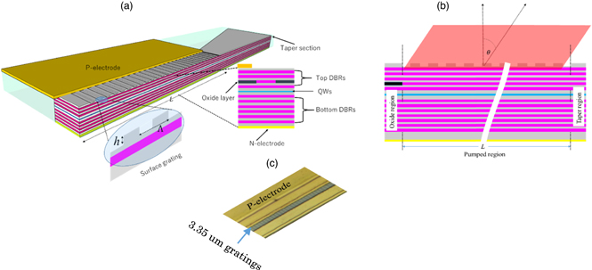
Fig. 1. (Color online) (a) Schematic structure of surface grating loaded VCSELs in the top view and in vertical direction. (b) The side cross section shows the radiation of slow light at angle (θ). (c) Microscope photo for the top view of fabricated device duty cycle of grating is 50%.
Download figure:
Standard image High-resolution imageWe have seen the following unique features in the proposed surface grating slow-light VCSELs. The phase refractive index Neff of a slow light is below unity, thus the pitch is as large as 0.6 μm even for the 1st-order grating at 850 nm wavelength band, which makes the fabrication of surface grating easy. We could make 2nd-order grating by using a stepper lithography. Also, the intensity of a slow light in a VCSEL structure is penetrated to the surface, a shallow grating with a depth below 100 nm gives us a large coupling strength in contrast to guided wave DFB lasers. Note that around 1 μm deep gratings are needed in surface grating DFB lasers reported in Refs. 31, 32. In addition, high power operation is not limited by catastrophic optical mirror damage as in edge emitting lasers because the output light is emitted from the entire length of the surface grating VCSEL. These are the unique features for our proposed device.
The coupling coefficient should be small enough to prevent the localized field intensity in the longitudinal direction and to increase the cavity length in mm-ranges. 32) A grating depth of 80 and 50 nm is employed in this experiment for cavity lengths 1 mm and 6 mm respectively. The fabrication steps remain the same as conventional VCSEL except the surface grating fabrication. In the beginning of the fabrication process, an extra step of wet-etching was performed to form the grating. Figure 1(c) shows the top view of fabricated device.
The fabricated device was tested at room temperature without electric cooler and heat sink for all of measurements. A large area (10 mm in diameter) silicon photodiode is used to measure the output power under continues wave (CW) operations while an avalanche photodiode with an integrated sphere is used to measure the output in pulsed operations. A multimode fiber tilted by angle θ to match a slow-light mode and connected into the spectrum analyzer to measure lasing spectra. Far field pattern (FFP) was also measured with a high resolution far-field measurement system (Synos M-Scope).
For comparison, we firstly investigate a long VCSEL aperture without gratings functioning as a Fabry–Perot laser. The oxide aperture dimension is 4 μm by 1 mm. Measured light-current characteristics show that output power is as high as 195 mW from the taper side. The photo-diode is tilted by 45° to collect slow light modes. The low reflection of the taper region causes a low output power of only 13 mW from the opposite oxide aperture end. A threshold current of slow light mode is around 50 mA and slope efficiency is about 0.6 W A−1 for a 18 pairs top DBR mirror which could be increased by reducing the top DBR reflectivity.
In Figs. 2(b) and 2(c), the lasing spectra are shown at two different current injections. At current I = 200 mA, three slow light modes appeared at wavelengths 844.6, 847.4 and 849.2 nm respectively. The number of modes has increased by increasing the current, because the gain bandwidth has increased and wavelengths shifted to longer wavelengths. Vertical light emission appeared with wavelength 869 nm at current I = 400 mA which interprets the rapid decreasing of the output power of slow light modes. The corresponding FFP of slow light mode are plotted in Figs. 2(d) and 2(e). Sharp lines related to slow light mode appear at angles depending on their wavelengths through Eq. (1). One also can see these lines shifted to the vertical angle at high currents. The long VCSEL aperture in mm-length shows multi-slow light-mode excitations at high currents.

Fig. 2. (Color online) (a) Output power versus current for a 1 mm long VCSEL without surface grating from the taper side (blue line) and from the rectangular side (orange line). (b) and (d) shows the spectrum and FFP at 200 mA respectively. (c) and (e) shows the spectrum and FFP at 400 mA respectively.
Download figure:
Standard image High-resolution imageNext, we show the selection of a fixed slow light mode in surface grating VCSELs. The oxide aperture size is 4 μm by 1 mm. The grating pitch is 3.35 μm with 80 nm depth for the 6th order grating. The coupling strength  between forward and backward waves is calculated as
  = 11 cm−1 for a grating depth of 80 nm and hence the coupling strength and length product is
  = 1.1, which is large enough for low threshold current operations. Light-current curve in the Fig. 3(a) shows output power of 134 mW at injection current I = 480 mA. Threshold current increased to 81 mA while the slope efficiency decreased to 0.39 W A−1. These penalties are caused by the radiation loss of high-order gratings as known for conventional high order DFB laser.
32) Although the output power obtained in the positive θ was reduced from 195 to 134 mW in the taper side, it increased on the opposite side. This is reasonable because of the feedback induced by gratings. The lasing spectrum of the device shows a single mode operation with wavelength 845.1 nm at current of 100 mA. Increasing of injection currents leads to wavelength shift to longer wavelength side as result of self-heating effect induced by CW current as shown in the Figs. 3(b) and 3(c). The wavelength reached at 850.7 nm before the roll-over of an output power at 500 mA. The current tuning range is 5.6 nm with a tuning rate of 0.014 nm mA−1. A side mode suppression ration (SMSR) is as high as 35 dB in the entire current range.
= 1.1, which is large enough for low threshold current operations. Light-current curve in the Fig. 3(a) shows output power of 134 mW at injection current I = 480 mA. Threshold current increased to 81 mA while the slope efficiency decreased to 0.39 W A−1. These penalties are caused by the radiation loss of high-order gratings as known for conventional high order DFB laser.
32) Although the output power obtained in the positive θ was reduced from 195 to 134 mW in the taper side, it increased on the opposite side. This is reasonable because of the feedback induced by gratings. The lasing spectrum of the device shows a single mode operation with wavelength 845.1 nm at current of 100 mA. Increasing of injection currents leads to wavelength shift to longer wavelength side as result of self-heating effect induced by CW current as shown in the Figs. 3(b) and 3(c). The wavelength reached at 850.7 nm before the roll-over of an output power at 500 mA. The current tuning range is 5.6 nm with a tuning rate of 0.014 nm mA−1. A side mode suppression ration (SMSR) is as high as 35 dB in the entire current range.
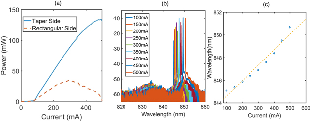
Fig. 3. (Color online) (a) Output power versus current from taper side (blue line) and from rectangular side (orange) for a 1 mm long VCSEL with surface grating. (b) lasing spectra at different currents from 100 up to 500 mA. (c) Lasing wavelength versus current under CW operations where the tuning range is about 5.6 nm.
Download figure:
Standard image High-resolution imageWe measured the FFP of the device at different currents as shown in the Fig. 4. While the spectrum shows the lasing wavelength is a single peak at 845.8 nm at 200 mA, the corresponding FFP displays four lines that indicate different diffraction orders in air. The FFP camera is moved in the positive angle range of 0°–70°. The zero-order diffraction angle is related to the effective index from Eq. (1). The other lines at m diffraction order determined from the grating equation as:


Fig. 4. (Color online) (a) FFP for a 1 mm long device in the range of 0° up to 70° at 200 mA. (b)–(d) FFP and corresponding images which are fixed at 37° at different currents of 300–500 mA.
Download figure:
Standard image High-resolution imageFor the VCSEL structure waveguide we used here, the cut-off (λc ) is 870 nm, the high order diffraction appeared at 29°, 14° and 0° as expected from the calculation. The distribution of the output power in high order diffraction may not be preferable in practical applications. To overcome this difficulty, we could reduce the grating depth and boost the power in the zero-order line, as we show later.
We focused on the zero and first order diffractions where the most of power concentrated. Although the wavelength is changed to a longer wavelength side, the FFP angles of two lines are almost fixed at same angles. This is because the cut-off wavelength shifts on the same direction, and the increase in refractive index caused by the self-heating effect could be compensated even at high injection currents.
We see the change of FWHM of FFPs as shown in the Figs. 4(a)–4(d). At a low current of 200 mA, the FWHM is 0.09° for the zero-order while it is 0.08° for first-order line, which are almost 1.2 and 1.4 times of diffraction limit, respectively. It's increased at higher current as 300 mA to become 0.1° for the zero-order diffraction and it becomes 0.09° for the first-order as shown in Fig. 4(b). For high current of 500 mA the divergence angle is increased to 0.13° and 0.12° for the zero and first orders respectively. The change of refractive index distribution along the long VCSEL aperture may have a large impact on the beam divergence. Two mechanisms of refractive index change caused by injection current takes place along such a long cavity. The first one is the temperature variation which is led to increase a refractive index. The second one could be the non-uniformity of injection currents. In particular, we used a single probe for injecting currents. By making multi-wire bonding, the second issue should be avoided. We also expect a narrower beam divergence by using heat sink and/or under pulse operations to avoid heat effects. The high output power and narrow beam divergence of slow light mode is promising for high resolution LIDAR applications.
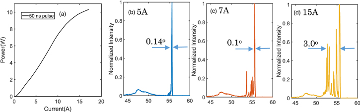
Further increase in output power and narrower beam divergence are expected by extending the VCSEL length up to 6 mm with a grating pitch of 2.52 μm for the 5th order grating. The grating depth is decreased to 50 nm to reduce high order diffractions in air. We use one probe to inject the pulsed current into such a long device. Current pulse width is 50 ns with repetition of 1 ms to reduce the self-heating effect and to increase high output power at high currents. Figure 5(a) shows an output power of 10 W obtained at 17 A with a slope efficiency of 0.6 W A−1.
Fig. 5. (Color online) (a) Light-current curve of a 6 mm long device under 50 ns pulsed operations. (b), (c) and (d) FFPs at different currents as 5, 7 and 15 A respectively.
Download figure:
Standard image High-resolution image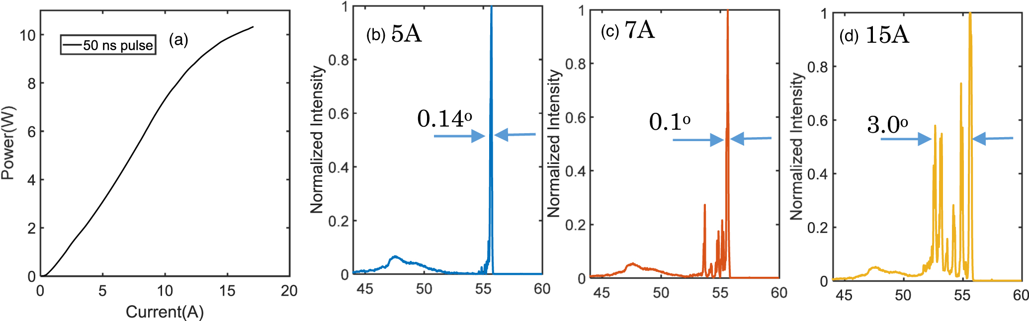
Figures 5(b)–5(d) show FFPs at currents of 5 A, 7 A and 15 A, respectively. The radiation angle is almost constant for the same reason mentioned before. Up to 5 A, the single line appeared in FFP with a divergence of 0.14° as shown in Fig. 5(b). The intensity of the first-order diffraction is less than 10% thanks to a lower grating depth. This shows a high output power of single mode operation as 3 W. Side peaks appear at 7 A because related to high order transverse lasing modes. Further increasing of current to 15 A, high side peaks grow up and beam divergence increased to 3.0°. Further increasing of output power of single mode is expected through improving the uniformity of injection currents along the long-cavity by the using multi-probe for current injection or wire-bonding.
In conclusion, we proposed and demonstrated a novel VCSEL structure with high-order surface grating for wide applications of high power and single mode VCSELs. The device length is extended into mm-long ranges to provide high power with high beam quality. A grating pitch is long enough to use standard photolithography thanks to small effective index of slow light modes. A 1 mm long device shows a single mode operation with an output power of 134 mW and SMSR ̃ 35 dB under CW operations. Multiple far field lines appeared as result of high order diffractions however beam divergence angle for each line is almost diffraction-limited. The single mode power of 3 W is obtained by avoiding heat effect under 50 ns pulse operations for a 6 mm long device. We work for better thermal management and improved uniformities by using wire bonding and heat-sinking. The fabrication process meets the VCSEL mass-production and these results shows a possibility of high-power single-mode VCSELs for use in 3D sensing and laser processing.
Acknowledgments
This work was supported by NEDO (#16100961-0).