Abstract
The friction behavior of metals is directly linked to the mechanisms that accommodate deformation. We examine the links between mechanisms of strengthening, deformation, and the wide range of friction behaviors that are exhibited by shearing metal interfaces. Specifically, the focus is on understanding the shear strength of nanocrystalline and nanostructured metals, and conditions that lead to low friction coefficients. Grain boundary sliding and the breakdown of Hall–Petch strengthening at the shearing interface are found to generally and predictably explain the low friction of these materials. While the following is meant to serve as a general discussion of the strength of metals in the context of tribological applications, one important conclusion is that tribological research methods also provide opportunities for probing the fundamental properties and deformation mechanisms of metals.
1 Introduction and Historical Perspective
The friction of bare metal contacts is of significant interest in the electrical contact community, where bare sliding metal contacts are ubiquitous in applications ranging in size from microswitches in mobile phones and ethernet cable connectors to slip rings in wind turbines and industrial-scale power generation systems. In these applications, many traditional lubricants would lead to an impractical decrease in electrical conductivity (i.e., an increase in contact resistance), compelling the use of pure, bare metal-on-metal contacts. The majority of these contacts consist of lightly alloyed gold, referred to throughout the community as “hard gold,” [1, 2] because of sub-percent additions of alloying elements that promote a finer, more thermodynamically stable grain structure with higher hardness [2]. In 2017, the amount of gold used in technological applications was estimated to exceed 300 metric tons per year, accounting for over 8% of the global yearly demand for gold. In total, this nearly matches the amount used by central banks and other institutions [3, 4], and approximately half of this amount is used in the form of coatings and thin films for electrical contacts [5, 6]. With current prices near $60 USD per gram, it is clearly of interest to fully understand the origins of friction in metal contacts, with a goal of designing alloys that reduce friction and wear, allowing for thinner coatings, greater longevity, and lower cost.
1.1 Early Studies of Metal Friction
In general, it would be expected that bare metals brought into contact would cold-weld [7, 8], leading to severe plastic deformation such as galling wear upon shearing [9, 10]. However, as will be discussed in detail below, it is, in fact, possible to achieve low friction with bare metal sliding contacts, although the mechanisms behind this phenomenon were unclear until recently. Metals tribology has been an active field of research since Amontons's work on the friction of copper, iron and lead, presented to the Académie Royale in 1699, although these surfaces were coated with pork fat, and therefore not bare [11]. One of the earliest recorded studies of the tribology of bare metals is from the late eighteenth century, when Hatchett and Cavendish were appointed to study gold coinage in the United Kingdom with a goal of understanding the origins of the sometimes substantial wear [12]. In this study, the two primary questions were (1) whether pure, soft gold wears faster than alloyed, hard gold (which, notably, was defined as alloys containing up to about 8% of elements including cobalt and nickel, similar to the hard gold alloys in use today) and (2) whether flat (smooth) or raised (rougher) surfaces wore faster. In general [12, 13], this work concluded that there was an inverse relationship between wear rate and ductility of self-mated gold contacts, and that softer metals wore fastest when in contact with harder metals. Finally, only a slight increase in wear was found for embossed coins.
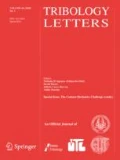
A more thorough investigation of wear, or “the friction of attrition,” was undertaken by Rennie [14] who studied the force required to move (a) blocks on flat surfaces and (b) axles with and without lubricants, with either matched (self-mated) or differing materials (see Fig. 1). A wide variety of metal contacts were tested, including cast and wrought iron, soft steel, brass, tin, and gun metal, and it was found that friction varied with hardness, with harder metals having lower friction. Rennie cited Hatchett and Cavendish’s work as further proof that harder metals show lower friction and wear than soft ones. Interestingly, this relationship between hardness and friction is often still used as the basis for engineering design of sliding metal contacts.

Depiction of Rennie’s 1829 friction testing apparatus [14]
These and other early measurements of friction only considered the average force necessary to start or maintain motion, and it was not until Bowden and Leben’s work [15] in 1938 that the fluctuations in friction during sliding were first examined (see Fig. 2). This work showed that surfaces in general, including metals, tend to exhibit stick–slip motion during sliding, a term that was coined in that paper and is still in use today. Many lubricants including mineral oil were used to achieve continuous motion, but in this early work only long-chain fatty acids seemed to provide adequate lubrication. A subsequent paper examined the adhesion between clean metals surfaces [8], including cold welding of metal surfaces and the associated increase in static friction. The authors discussed the changes in adhesion due to surface films, including adsorbed organic species and oxides, and interestingly included a reference to earlier work by Ewald et al. [16] stating that friction between clean, polished surfaces in a vacuum (though metals are not specifically mentioned) can be very small. Bowden and Tabor continued their work on metals friction, proposing a mechanism of friction between metals by recognizing that the true contact area is determined by the applied or surface-normal load. This resulted in the constitutive equation, \(\mu = \frac{\tau }{\sigma }\), where μ is the friction coefficient, \(\tau\) is the shear strength, and \(\sigma\) is either the normal contact pressure or, as a bounding limit, the flow strength of the material [17] (we expand on this relationship, below). Bowden and Tabor cite a similar relationship attributed to Rabinowicz [18] from the proceedings of the “Conference on Friction and Surface Finish,” in 1940.

Earliest known example of metals friction data, showing stick–slip behavior of copper sliding against steel, reproduced from Bowden and Leben in Nature, 1938 [15]
While many studies of friction between metal surfaces exist, demonstrations of low friction, loosely defined here for metals as µ < 0.5, were rare for several decades following this early work, and only seemed to be mentioned in passing [8, 16, 19] as a curiosity. More recent work investigating this phenomenon will be discussed below, but as Bowden & Tabor point out [17], metallic friction is a surface effect, and it is therefore important to understand the effects of surface treatments, shear in particular, on the surface microstructure.
1.2 Surface Microstructural Evolution—The Beilby Layer
Sir George Beilby’s seminal studies of the surface of polished metals showed that the surface layer has a grain structure different from that of the bulk material, but concluded that there was no observable crystallinity, and that the surface was, instead, vitreous or amorphous [20]. Beilby proposed [21] that this distinct surface layer was formed through localized liquefaction (or fluid-like molecular flow) followed by rapid cooling to an amorphous state, and noted that the hardness of the surface increased after polishing. Adam [22] commented in 1927 that this phenomenon did not require actual melting, as random rearrangement of atoms near the surface would have the same appearance as a supercooled liquid. Finch, Quarrell and Roebuck [23] performed experiments on various metals and agreed with Beilby’s ideas of molecular flow. In a simple calculation, Bowden and Hughes [24] showed in 1937 that the frictional energy released during a typical polishing operation is many orders of magnitude larger than that needed to generate a melt layer with a thickness comparable to the observed Beilby layer. However, in contrast to these works supporting Beilby’s claims, much of the early discussion in the 1930s concluded that there were, in fact, nanocrystalline grains formed on the surface. The controversy surrounding the nature of the Beilby layer continued into the later parts of the century, with studies on steel [25] and copper [26, 27] specifically stating that no Beilby layer was found on deformed metal surfaces. The development of the transmission electron microscope (TEM) in 1928 was crucial to understanding the formation of nanocrystalline surface films, and while Hamburger [28] in 1932 claimed to have been able to resolve aggregates of size ranging from 3 to 30 atoms, the first TEM image of a polished gold surface was not shown until 1938 by Cochrane [29], who estimated the surface grain size to be on average 2–3 lattice constants, or approximately 8–12 Å. Note that this range of grain sizes is close to the critical grain size proposed for gold surfaces by a recently developed predictive model [30], below which the shear strength is expected to decrease rapidly, as discussed in Sect. (3.2). Further discussions of nanocrystallinity at a polished surface can be found in Bowden and Hughes [24, 31], who in 1937 commented that there may be little point in distinguishing between amorphous and microcrystalline surfaces, and Buckley [32], who commented that the Beilby layer is the result of repeated deformation-induced grain refinement and recrystallization at the surface (not melting, as originally proposed by Beilby [20]) resulting in very fine grained material.
In addition to a change in the microstructure at the surface, it has also been clear for some time that different layers appear in a metal below the surface following deformation. The first discussions of the various surface layers were published in 1932 by Nieberding [33], who showed changes in the microstructure of aluminum during cutting and indentation (see Fig. 3), and Hamburger [28], who in his work on the Beilby layer mentions that the microstructure showed a continuous change from the small crystallites at the surface, through a thick layer, and finally to the bulk material.

Early cross-sectional metallurgical analysis showing deformation layers after indentation, reproduced from Nieberding, Maschinenbau, 1932 [33]
It appears that the connection between microstructural evolution under frictional loading and the Beilby layer formed by polishing, whether amorphous or nanocrystalline, was only explicitly stated recently [30, 34, 35]. Goddard et al. [36], who also made an early connection between hardness and friction for metals [37], discussed the changes in microstructure in FCC metals under abrasive load and found that the surface consists of “randomly oriented fragments.” Interestingly, this work also discusses the changes in the material under the surface as consisting of distinct layers, with thicknesses of 0–5 nm, 5–10 s of nm, 10–100 s of nm, and transitioning below that to a coarser grained bulk. In general, though, this work was focused on the orientation of the grains after sliding rather than a quantification of grain sizes. As pointed out nearly two decades later by Ohmae, Tsukizoe and Akiyama [38], this was likely due to the difficulty in preparing TEM samples from worn surfaces, which are typically rough and irregular.
The remainder of this review explores the relationship between deformation mechanisms and friction behavior of metals, specifically highlighting the formation of interfaces with extremely refined grain sizes under sliding contact, with a corresponding reduction in friction coefficients and wear rates. As the field of deformation-induced microstructural evolution and its relationship to materials properties is extremely heavily published, it is necessary to focus on work that establishes a link between microstructure and friction. We mostly restrict the discussion to contact conditions where the competing phenomena of shear-induced grain refinement and growth of metallic interfaces are dominant, avoiding, for example, regimes that lead to frictional melting, or experiments in reactive environments that lead to the formation of thick oxide or mixed metal-oxide films; in those cases, friction behavior is not meaningfully linked to the deformation mechanisms of crystalline metals.
2 Effects of Microstructure on Mechanical Properties
The theoretical strength of a defect-free metal crystal \(\left( {\tau _{{th}} } \right)\) was first estimated by Frenkel [39] in 1926 as the ratio of its shear modulus (G) and a geometric constant associated with the periodicity of the atomic spacing, \(\tau _{{th}} \cong \frac{G}{{2\pi }}\). This model was subsequently refined, predicting slightly smaller strengths [40, 41]. However, measured strengths are still typically much lower due to the presence of defects, such as crystal lattice dislocations, that themselves create energetically more favorable conditions for the creation or nucleation and annihilation of more defects [42,43,44,45]. Conversely, metals can also become stronger due to interactions between defects, including vacancies or interstitial atoms (point defects), dislocations (line defects), grain boundaries (planar defects) and/or particle inclusions (volumetric defects), that act to impede their motion. The increase in shear strength (\(\Delta \tau\)) with defect density follows a general scaling law, corresponding to a ratio of the force (F) required to overcome the energy barrier due to dislocation-obstacle interactions and a characteristic length-scale parameter (e.g., the magnitude of the Burgers vector, b) multiplied by the average distance between obstacles (L) [46, 47], \(\Delta \tau = \frac{F}{{bL}}\).
In 1934, Taylor [48] derived a general equation for the strengthening that occurs in metals as a function of dislocation–dislocation interactions, where the increase in shear strength was given as, \(\Delta \tau _{d} = \alpha Gb\sqrt \rho\). The parameter α is a constant that describes the type of dislocation interaction [49], G is the shear modulus, b is the Burgers vector, and ρ is the dislocation density, assumed to be randomly distributed. The same year, Orowan [50] and Polanyi [51] derived similar expressions to describe the strengthening due to interactions between dislocations and hard particles. In the 1950s, Hall [52] and Petch [53] independently showed that the yield strength of materials in simple tension varies with grain size according to the empirical relationship, \(\sigma _{y} = \sigma _{0} + k \cdot d^{{ - 1/2}}\), where \(\sigma _{0}\) and k are material- and temperature-dependent constants, and d is the grain size. The relationship between yield strength in uniaxial tension \(\left( {\sigma _{y} } \right)\) and pure shear \(\left( {\tau _{y} } \right)\) is given as, \(\sigma _{y} = \sqrt 3 \cdot \tau _{y}\), following Maxwell-Huber-von Mises-Hencky (distortion energy) theory [54,55,56,57].
Even though the effects of microstructure and its evolution (including grain size, defect density and type, and their creation and motion) on the friction behavior of metals were not well understood until recently, it has been clear for some time that these are fundamentally linked to mechanical properties like strength. Nanocrystalline pure metals and alloys, which have a high density of grain boundaries, can have exceptionally low friction and high wear resistance [1, 58,59,60,61,62,63,64,65,66,67,68,69,70,71,72,73,74,75]. Even initially pure, coarse grained metals can be driven to extreme refinement and low friction and wear during sliding [30, 58, 76,77,78,79,80], where the Hall–Petch effect again becomes critical to understanding the strength of shearing metal interfaces [30]. The details of the Hall–Petch effect are beyond the scope of this review, and have been the subject of a recent comprehensive review by Cordero, Knight and Schuh [81]. However, it is important to note that there is a crucial flaw in the Hall–Petch formula, namely the implication that the yield strength or hardness of a material increases indefinitely as the grain size becomes smaller—a result that is clearly unphysical. It is therefore expected and found that there exists a grain size, hereafter referred to as the critical grain size \(\left( {d_{c} } \right)\), below which the Hall–Petch relationship no longer holds; this is shown in Fig. 4 for a variety of experiments and simulations of metals with different crystal structures [82,83,84,85,86,87,88,89,90].

Because pure metals with an average grain size on the order of dc are thermodynamically driven to rapid grain growth even at low homologous temperatures and low applied stresses, it is difficult to experimentally probe this range of grain sizes. Dilute alloying can mitigate grain growth by thermodynamically and kinetically limiting the movement of grain boundaries, as explained in Sect. 4.2. This approach has led to controversy about what relationship truly exists between yield strength and grain size for pure metals below this critical grain size. As pointed out by Cordero, Knight and Schuh [81], however, many experiments and simulations have shown that below a critical grain size the Hall–Petch relationship is no longer accurate, leading to what is commonly referred to as inverse Hall–Petch behavior, Hall–Petch breakdown, or Hall–Petch softening [76, 81, 83, 85, 86, 91,92,93,94,95,96,97,98,99,100,101]. As we will discuss below, because tribological sliding contacts typically experience persistent, high strain rate deformation at the sliding interface, the competing kinetics of grain refinement and growth present a tantalizing opportunity for studying this phenomenon in pure metals.
The proposed explanation for the grain size-dependent transition between two different deformation and strength regimes (i.e., Hall–Petch strengthening above and softening below the critical grain size) is related to the energetics of dislocation activity in nanocrystalline grains. Transitions in strength implicitly include shear strength, and thus are also directly linked to friction regimes, as discussed later. In FCC metals with grain sizes too small to accommodate intragranular dislocation nucleation mechanisms, as with Frank-Read sources [42], the emission of partial dislocations from grain boundaries becomes favorable [102,103,104]. Specifically, leading partial dislocations are emitted from grain boundaries and, depending on parameters including crystal structure and grain size, travel across the grain and are either absorbed by the opposing grain boundary or followed by the emission of a trailing partial dislocation, creating a stacking fault [45, 105, 106]. The size of the stacking fault, which is dependent on the applied stress, is the splitting distance between the partial dislocations. The relationship between this splitting distance and the grain size determines whether the generated dislocations can accommodate the applied stress or not. These relationships have been extensively explored in publications by Yamakov et al. [103], and Frøseth et al. [105], and are beyond the scope of this review. While some disagreement exists in the literature [105], Yamakov et al. [103] claim that as the grain size decreases dislocations become harder to generate and move until the critical grain size is reached, and the deformation mechanism changes from dislocation mediated to grain boundary sliding. It is this change in deformation mechanism that leads to the crossover between Hall–Petch strengthening (dislocation mediated) and inverse Hall–Petch softening (grain boundary sliding). Recent work, however, has demonstrated that exclusively separating deformation into these two regimes is overly simplistic, and that both mechanisms contribute to strength [90].
To better understand the relationship between grain size and splitting distance, it is worthwhile to briefly review the underlying theory. By balancing the forces between glissile (mobile) Shockley partial dislocations, Frøseth et al. [105] show that the splitting distance for pure edge dislocations \({r}_{e}\) can be reduced to,
where \(\upsilon\) is Poisson’s ratio, \(G\) is the shear modulus, \({b}_{p}\) is the magnitude of the Burgers vector for the partial dislocation, and \({\gamma }_{SF}\) is the stacking fault energy. The splitting distance is affected by applied stress as [103, 106],
where \(\sigma\) is the applied shear stress, and the parameter \({\sigma }_{\infty }\) is the shear stress at which the partials are split infinitely far apart, representing a theoretical maximum shear strength limit [103]; this stress is given by \(\frac{{2\gamma _{{SF}} }}{b}\) [105]. Yamakov et al. combined the splitting distance, shear strength limit and an estimate of the nucleation stress for dislocations in the nanocrystalline regime [107], \(\sigma _{n} \propto \frac{1}{d}\), where \({\sigma }_{n}\) is the nucleation stress and \(d\) is the grain size, to develop a deformation map (see Fig. 5) that generally describes the different regimes of stress and grain size that lead to either dislocation-mediated plasticity (DMP) or grain boundary sliding (GBS) as the dominant deformation mechanism [93, 103]. The details of GBS as it applies to friction will be discussed in detail, below. Note that in Fig. 5, \({r}_{0}\) is the same as \({r}_{e}\) in Eqs. 1 and 2, above. This deformation mechanisms map, while useful, is purely static (time independent), and we describe how this map has been recast for use in time-dependent tribology below.

Deformation mechanism map as a function of reduced stress and grain size, reproduced from Yamakov et al., Nature Materials, 2004 [103]
The analysis above, even considering disagreements surrounding the actual mechanics, shows that a change in grain size in the nanocrystalline regime can affect the available deformation mechanisms. The connection of these mechanisms to tribological processes is through the effects of repeated or cyclical shear stresses on the grain structure. From the work of Beilby and those either confirming or refuting his ideas, it is clear that shear at the surface—whether from polishing or sliding metal contacts—can lead to a distinct change in the surface microstructure of a metal. The widespread availability of TEM has also shown that metal contacts with low friction are commonly associated with the formation of an ultra-nanocrystalline (rather than amorphous) surface film. The work of Yamakov and others on the inverse Hall–Petch effect shows that extreme grain refinement comes with an associated change in deformation mechanism from DMP to GBS, with a concomitant change in the strength of the material in this region. However, it is also well known that applied stress will cause coarsening of metallic microstructures [46, 77, 108, 109], leading to the questions of what conditions lead to extreme refinement at the surface and when this phenomenon dominates.
2.1 Effective Grain Refinement Via Dislocation Cells
As discussed earlier, in nanocrystalline FCC metals leading partial dislocations are emitted from grain boundaries and, depending on the crystal structure and grain size, can travel to an opposing grain boundary before the trailing partial is emitted. If this occurs, an extended stacking fault remains in the grain, pinned to the grain boundary where it originated and terminated on the other end by a partial dislocation [103, 105, 106]. It is well known that stacking faults can act as barriers to slip [110, 111]. When the stacking fault energy is low, the separation between dislocations is large, and cross-slip becomes more difficult in small grains. Additionally, dislocation networks can act as an obstacle to intragranular deformation, effectively analogous to smaller grain size in terms of strengthening. Dislocations tend to aggregate to form forest dislocation arrays which can, in turn, transform into dislocation cells or grain sub-boundaries upon further deformation. Further applied stress can then cause these sub-boundaries to rotate, leading to subgrain hardening [112].
This grain refinement mechanism has been studied in the recrystallization literature, where it has been shown that subgrains and dislocation arrays can lead to a more equiaxed microstructure with a steady-state grain size that depends on material properties and strain rate [112, 113]. As early as 1967, McQueen et al. discussed the development of a substructure that does not change with further deformation [114], and showed a linear relationship between subgrain size and the Zener-Hollomon parameter [115] (see Fig. 6). The average cell size has also been linked to an extrusion stress and deformation rate [114], flow stress during deformation [116] and the applied shear stress [117,118,119].

Relationship between subgrain size and strain rate, reproduced from McQueen et al., 1967 [114]
From ball- and cryo-milling studies, it is believed that these subgrains transform through grain rotation first into low-angle (more ordered) and then into high-angle (less ordered) grain boundaries, forming a nanocrystalline structure [120,121,122,123]. Once the nanocrystalline structure is formed, it is then possible—assuming the grains are smaller than the critical grain size—for applied deformation to be accommodated through grain boundary sliding.
2.2 Stress-Driven (i.e., Non-diffusive) Grain Boundary Sliding and Friction
Sliding contacts are arguably a useful method to test these theories. For polished metal surfaces, with average surface roughness that can be less than 50 nm, it is possible to apply contact stresses that do not exceed the bulk flow stress, at least for a limited time. In the absence of lubrication, and at sliding speeds that cause a negligible increase in surface temperature [124], severe plastic deformation will occur readily [125]. Additionally, it has been widely observed that deformation is highly contact interface/surface-localized [126] during shear of metals at low speeds and contact forces, leading to high strain rates, with 102 s−1 being an estimate of strain rate for a contact with a Hertz radius of 10 µm sliding at 1 mm/s [125]. The high strain rates and short time span between contact events during cyclic sliding leads to the rapid formation and persistence of an ultra-nanocrystalline (or near amorphous) surface film. The persistence of this highly refined layer (with the understanding that it is the average grain size that persists, rather than the individual grains themselves) can obviate issues regarding the stability of nanocrystalline grains and maintain the surface material in the inverse Hall–Petch regime, where, as discussed in detail above, grain boundary sliding is expected to be the dominant deformation mechanism [34, 127].
In this case an interesting link appears between low friction in metals and superplasticity, a phenomenon in which pure grain boundary sliding has been proposed as the mechanism that allows some metals to be deformed (in tension) to extremely high strains, typically at high temperatures. One remarkable example is nanocrystalline bulk copper that was extended to over 5000% strain at room temperature [128]. This connection was briefly speculated on in 1983 by Heilmann et al. [129]. In the initial stages of shearing contact between bare metals, cold welding occurs, and grain boundaries are formed at the sliding interface [24]. The model proposed in [30], predicts that low friction can result when grain boundary sliding becomes the dominant deformation mechanism.
In 1976, Mohamed and Langdon [130] mapped the different flow mechanisms for two alloys as a function of normalized shear stress (divided by shear modulus) and grain size (divided by Burgers vector) (see Fig. 7). The stresses in metals tribology are generally on the order of 100 s of MPa (see below), and with shear moduli generally in the 10 s of GPa, the normalized stress is then typically ~ 10–2. Grain sizes in the inverse Hall–Petch regime are 10 s of nm, placing low friction metal contacts beyond the lower right boundary of their published deformation mechanisms map, and clearly in the superplastic regime [130]. Interestingly, as was mentioned by Langdon and further studied by Ginter and Mohamed [131], the average subgrain size formed during creep (and upper limit for superplasticity) is generally \(\frac{d}{b} = 10\left( {\frac{G}{\tau }} \right)\), as shown by the dashed lines in the figures; with the estimates of tribological shear stresses above, this also places the critical grain size at less than ~ 100 nm. Solving for shear stress, \(\tau = \left( {\frac{G}{{10}}} \right)\left( {\frac{d}{b}} \right)\), this also implies that, when grain size is on the order of the Burgers vector magnitude (d/b ≈ 1; i.e., at the amorphous limit), the shear stress upper limit for superplastic behavior is approximately equal to the Frenkel estimate for the ideal strength of defect-free crystals; this is an unexpected and likely spurious coincidence.

Deformation mechanism maps for Zn–Al and Pb–Sn alloys, reproduced from Mohamed and Langdon, 1976 [130]
It is important to note that the grain boundary sliding discussed here is distinct from diffusive mechanisms, such as Nabarro-Herring [132, 133] or Coble creep [134], and will be discussed in detail, below.
The empirical formula [135] used to describe superplasticity relates the flow stress \(\left( \sigma \right)\) to a power law of the strain rate \(\left( {\dot{\varepsilon }} \right)\),
where \(\sigma _{c}\) is a critical stress, \(\beta\) is a materials-specific constant [136], and m is the strain rate sensitivity. Superplasticity is said to occur when \(m \ge 0.3 - 0.5\) [136, 137], with pure grain boundary sliding corresponding to \(m = 1\) [135]; in the latter case, \(\sigma _{c}\) is an aggregate critical shear strength of the grain boundaries in the system, \(\beta\) is an effective grain boundary viscosity [135], and the equation essentially describes flow of a Bingham plastic.
2.3 Viscous Grain Boundary Sliding
Many theories of GBS consider diffusional creep mechanisms [138], whereas the GBS discussed here is more of a viscous nature. The treatment of grain boundaries as viscous layers likely began with the work of Rosenhain and Ewen [139], who described an intercrystalline “cement” that was analogous to an undercooled liquid, a concept that was further developed in more recent work by Zhang et al. [140]. This intercrystalline glassy material was said to be continuously forming during deformation, followed by rapid recrystallization when deformation stops, and to act as an intervening viscous liquid that is soft enough to allow deformation to occur at the boundaries between crystallites. In 1938, Moore et al. [141] similarly explained creep deformation occurring through viscous flow at grain boundaries, and their discussion could be interpreted as describing amorphization of grains under stress; that same year, Kanter [142] described those experiments as “grains swimming within their boundaries.” Kê [143] later showed more experimental evidence of viscous grain boundaries through low stress torsion experiments on aluminum and proposed a simple activated creep model. Mott followed with a more detailed model of slip at grain boundaries, developing an activated model (similar to those of Prandtl [144] and Tomlinson [145] for friction, and Eyring [146] for viscosity) that considered melting of ‘small, mismatched islands of atoms’ at grain boundaries. Mott said the activation energy for this process, citing Frenkel [147], is close to the latent heat of fusion; specifically,
where \(\Delta F\) is the free energy change, L is the enthalpy of fusion, T is temperature, and Tm is the melting temperature. This relationship can be easily derived by calculating the energy required to amorphize a crystal (see Devereux [148], pp.21ff, for example). These models [144,145,146] assume an activated process that is either assisted or hindered by an applied stress, causing both forward and backward jumps, and resulting in a hyperbolic sine of the stress. This functional form appears in many later formulas for grain boundary sliding. Kauzmann [149] gives the same temperature-dependent energy difference between amorphous (specifically an undercooled liquid) and crystalline material as Mott and, in deriving an expression for activated diffusion in glasses, points out that when the externally applied energy (shear stress, in the case of friction) is large, the second exponential representing backward jumps is negligible. In this case, only the first term (i.e., where external forces lower the activation barrier) is important.
The heat of fusion was also used as an activation energy (or to describe the energy difference between amorphous and crystalline phases) in work by Jackson and Chalmers [150], who in a description of melting rates added the assumption that interfacial energies scale with the number of missing neighbors, Bolling [151] in a model for high-angle grain boundaries (that also included liquid–solid surface energies), Moss et al. [152] in a description of amorphous Ge, and by Spaepen [153], and Thompson and Spaepen [154] as part of a more complex derivation. Others have used the activation energy for viscous flow [155] and amorphous diffusion [156].
The number of models describing grain boundary sliding increased in the 1990s after experimental demonstrations of inverse Hall–Petch behavior in Cu and Pd by Chokshi et al. [82] and Fougere et al. [157], in Cu by Cai et al. [158], in Zn by Conrad and Narayan [85], and in Ni by El-Sherik et al. [159] and Erb [84]. Again, as pointed out in the review of the Hall–Petch effect by Cordero et al. [81], experimental results in the inverse Hall–Petch regime are quite difficult to carry out, because grain sizes less than 10 nm in pure metals are inherently unstable to stress and temperature. For this reason, many results demonstrating softening are from alloys, where the alloying constituents pin grain boundaries and slow grain growth (see below), or from simulations [83, 86, 88, 91, 101, 160], where short time scales obviate excessive grain growth. Recent experiments on nanotwinned copper [161]have been shown to reproduce yield strength data for large grain sizes, and still remain stable in the inverse Hall–Petch regime, giving results for effective grain sizes down to 4 nm, though it is not clear that the strengths of nanotwinned and nanocrystalline metals are the same.
From their data, Chokshi et al. [82] proposed Coble creep as the mechanism (with a d3 dependence for the strain rate), but this was shown to be incorrect by Nieh and Wadsworth [162]. In fact, while many models of grain boundary sliding focus on creep mechanisms with grain size dependencies of d2 or d3, the high shear rates of tribological processes (typically of order 102 s−1) obviate the application of diffusive mechanisms such as these. We will instead only discuss the models that consider viscous sliding. Padmanabhan et al. developed a model for superplasticity and grain boundary sliding that proposes a threshold stress is necessary to flatten the interface between grains and effectively create new boundaries [163, 164]. A similar description of the mechanism, termed cooperative grain boundary sliding (CGBS), was proposed in, for example [165,166,167,168] (Fig. 8A).

A Cooperative grain boundary sliding model proposed and evidence of intragranular amorphization via shear band formation initiated at triple junctions, reproduced from Kaibyshev (2002) [166], and B recent experimental and atomistic simulations showing this mechanism in SmCo5 alloys, reproduced from Luo et al. (2019) [169]
This effect has recently been seen for alloys (Fig. 8B) and ceramics in experiments and simulations [169, 170]. Van Swygenhoven and Caro [171], however, assumed that no new boundaries are created and used a slip-dashpot model with a strain rate dependence of d−1. This model was later expanded to an Eyring-like model with viscous flow [160], similar to one proposed by Schönfelder et al. for grain boundary migration [172]. Parameters for this model were proposed by Conrad and Narayan [94] to fit the data from Chokshi et al. [82], and then later used by van Swygenhoven and Derlet [173] and Conrad [174]. Conrad’s later work [174, 175], however, used data from Cai et al. [158] on nanocrystalline copper. Song et al. developed a “coherent polycrystal model,” in which grains act as particles that strengthen the grain boundaries, proposing an expression that is combined with the Hall–Petch response [176]; their model was fitted to experimental data for Zn, Ni–P and Ti–Al, and was later used for Zn by He et al. [177]. A different model that combines intragranular and grain boundary mechanisms was proposed by Yang and Ghosh [178], who use a description of a grain boundary “mantle zone” area. When grain sizes are on the order of 5–10 times the thickness of grain boundaries, these zones are easily connected, and stress no longer needs to be accommodated by the interior of grains. This idea yet again places a critical grain size at about 10 nm, with the thickness of grain boundaries assumed to be between 0.5 and 1.5 nm [179].
Wei et al. [180] developed a strain rate-dependent amorphous plasticity model describing grain boundary sliding in FCC nanocrystalline metals. Their model predicts that intergranular failure along grain boundaries should result in cavitation at triple junctions and other locations of high stress, and may explain nanoporosity commonly observed inside low friction wear tracks of pure metals in inert gas or vacuum environments [77] (see Fig. 9). As Kumar et al. [181] explained in an earlier publication, “Triple junction voids and wedge cracks can also result from grain boundary sliding if resulting displacements at the boundary are not accommodated by diffusional or power law creep.” This explains evidence of interspersed nanoporosity in shear layers only when low friction and grain boundary sliding are achieved.

Examples of voiding that occurs due to sliding deformation in nanocrystalline metals, a from Prasad et al. [77], and b unpublished from self-mated high-purity copper sliding experiments in ultrahigh vacuum (10–9 torr) where low steady-state friction coefficients were measured (\(\mu _{{ss}} \cong 0.36\)); image of the same location after annealing for 15 min at 400 °C shows evolution of feature geometry, from elongated to more equiaxed, confirming the white features as voids or pores
Most of these models assume viscous flow at the grain boundaries, and therefore use an activation energy that is based on the energy difference between amorphous and crystalline phases. This energy is usually assumed to be related to the heat of fusion, L, as this is a measure of the bond strength of the material. For tribological processes, the strain rate can similarly be considered as an activated process, with an energy barrier that is lowered by the stress. Note that, as in Kauzmann’s review [149], the sliding contact can be treated as being driven in the “forward” direction, assuming that backwards jumps due to stress are negligible, resulting in a simple exponential rather than a hyperbolic sine function. Such an expression for strain rate can then be written as:
where \(\dot{\varepsilon }\) is the strain rate, \({\dot{\varepsilon }}_{0}\) is a fundamental strain rate, \(\Delta F\) is the activation energy, \(\tau\) is the applied shear stress, V* is the activation volume, T is temperature and k is Boltzmann’s constant. When the grain size is small, the grain boundaries should be able to form a connected shear layer, as in Yang and Ghosh [178], and when the grain size increases, stresses will be transferred to the core region of the grains, where amorphization will be required to continue shear, similarly to the model of Padmanabhan et al. [163, 164], and the effects seen in Guo et al. [170] and Luo et al. [169]. The activation energy, then, is that required for amorphization of a crystal. There are two possible energies to describe this process, notably grain boundary energy (i.e., the energy difference between a grain with a perfect lattice and one that is transected by a new boundary), or the heat of fusion per unit volume (i.e., the energy difference between crystalline and amorphous phases, as discussed above). The heat of fusion is potentially more accurate, as grain boundary energies from the literature are averaged over a range of grain boundaries, and not just the high-angle (closer to amorphous) boundaries that are likely to be active in shear. A recently developed predictive model for GBS with no adjustable parameters [182] uses an activation energy given by,
where \(\rho _{L}\) is the density of the liquid at Tm, M the atomic mass, T is the temperature, Tm is the melting temperature, fg is the volume fraction of crystalline material in the grains, and V* is the activation volume. In Eq. 6, the heat of fusion (in J/mol) is divided by an atomic volume (i.e., multiplying by density over the atomic mass) to get an atomic or specific heat of fusion that is multiplied by the same activation volume as the stress term. The liquid density in Eq. 6 is an approximation of the density of the amorphous solid. This activation energy was shown to be nearly equivalent to high-angle grain boundary energies divided by an approximate grain boundary thickness [183], similar to the method described in Shvindlerman and Gottstein [184] (see Fig. 10). As this treatment assumes amorphization of crystalline material, the activation volume is taken to be the Burgers vector magnitude cubed, i.e., b3, to represent single atomic motions [173]. The factor fg is the volume fraction of crystalline material in a grain, as in the coherent polycrystal model [176], \(f_{g} = \left( {\frac{{d - \delta }}{d}} \right)^{3}\), with \(\delta\) being the grain boundary thickness. This factor limits the energy barrier for amorphization to the crystalline phase only, as the grain boundaries are assumed to be effectively amorphous already. This is justified by considering that high-angle grain boundaries, which are prevalent in highly deformed metals [185, 186], have volumetric energies that are proportional to the heat of fusion (Fig. 10).

Specifically, for tribological processes, the fundamental strain rate \(\dot{\varepsilon }_{0}\) in Eq. 5, can be taken to be:
where Ng is the number of grains being sheared, and \(t_{c} = \frac{v}{a}\) is the contact time, where v is the velocity, and a is the Hertz contact radius. Considering the region undergoing shear to be a cylinder of radius a and depth d, results in the number of grains being approximately \(N_{g} = \frac{{\pi a^{2} d}}{{\tfrac{4}{3}\pi \left( {\tfrac{d}{2}} \right)^{3} }} = 6\left( {\frac{a}{d}} \right)^{2}\). Expanding the exponential to first order and rearranging terms gives,
Comparing this equation to Eq. 3 leads to two conclusions. First, that the fundamental shear strength of a layer of grains in the grain boundary sliding regime is
And that the shear rate is governed by an effective viscosity of the grain boundaries,
This effective viscosity \(\eta _{{eff}}\) is similar to the viscosity of liquid metals, approximately 1–10 mPa-s.
Figure 11 presents data from experiments and simulations on the shear strength of multiple metals as a function of grain size and shows that the theoretical predictions from this amorphization model are accurate in the inverse Hall–Petch regime. The experimental data demonstrate a large spread in the measured shear strength at all grain sizes, likely due to a variety of reasons, including differing strain rates and error-prone estimates of grain sizes over a narrow range (i.e., in the regime where d < 10–20 nm) where they are actually dynamic and heterogeneous. Nevertheless, in the dislocation-mediated plasticity regime (i.e.,\(d > d_{c}\)), the data can be reasonably fit with the classic Hall–Petch relationship, as shown by the blue lines, using the fits from Cordero et al. [81]. In the figure, all data have been converted to shear strength from yield strength through the von Mises yield criterion, \(\tau _{Y} = \frac{{\sigma _{Y} }}{{\sqrt 3 }}\). Asaro et al. [45] provided a mathematical framework to accurately predict the stress required to nucleate dislocations at grain boundaries in the nanocrystalline regime, above the critical grain size below which inverse Hall–Petch behavior becomes dominant,

a Comparison of aggregate experimental (crosses) [81, 82, 161, 189] and computational (circles) [101] strengths, best fits for Hall–Petch strengthening from Cordero et al. [81] (blue or black lines), and (red lines) predictions from the amorphization model for quasi-static and dynamic cases, from Chandross and Argibay [182]. b Overlay of model prediction (red lines) [182], molecular dynamics simulation results (circles) showing inverse Hall–Petch behavior with nanocrystalline Au, from Liu et al. in 2020 [89], experimental strengths (crosses) with best fit (blue line) Hall–Petch strengthening from Cordero et al. [81] and nanocrystalline strength prediction (green line) from Asaro et al. [45] for Au and SmCo5; the SmCo5 plot shows an overlay of model predictions (red lines) using a rule of mixtures based on atomic fractions and grain size-dependent strength data from simulations and experiments from Luo et al. [169]. In all cases, dashed lines correspond to extrapolations, for visualization purposes, where the respective prediction model fits are not applicable or relevant (color figure online)
As Asaro et al. [45] point out, there is an implicit assumption ignoring the orientation of slip planes (i.e., the Taylor factor), so that the applied shear stress is assumed to be on the slip plane at all times, and thus equal to the resolved shear stress. Padmanabhan et al. [188] address this assumption (in the context of shear strength in the inverse Hall–Petch regime) and find that the error in equating applied and resolved shear stresses is inconsequential. While neither the fit from Cordero et al. [81] or the prediction from Asaro et al. [45] can completely describe the data in Fig. 11, both broadly describe the data and, in particular, show good agreement for grain sizes in the nanocrystalline regime above the critical grain size. Figure 11 also shows that the grain size and strength for the crossover between GBS and DMP (~ 10 nm) is reasonably well predicted by the intersection of the prediction from Eq. 9, and with the prediction from Asaro et al. [45] shown for Au in Fig. 11b.
The link between grain size-dependent shear strengths and friction coefficients will be discussed in detail below. However, one can rather accurately and generally estimate a friction coefficient for metal contacts based on surface and bulk grain sizes. Using the Bowden and Tabor formula from Sect. 1.1, the friction coefficient is approximately the ratio of shear strength (from Eq. 9) to the hardness, that for nanocrystalline metals can be determined by multiplying the shear strength from Eq. 11 by the von Mises factor of \(\sqrt 3\) and the Tabor factor of 3 [190].
3 Linking Deformation Mechanisms, Microstructure, and Shear Strength
3.1 Microstructure and Friction
Microstructural evolution below wear surfaces has been the subject of numerous studies [129, 191,192,193,194,195,196,197,198,199,200,201,202], but the true effect of microstructure on friction has been elusive. Rennie’s studies in the 1800s [14] showed a link between hardness and friction, and Goddard and Wilman in 1962 [37] showed a nearly linear relationship between the friction coefficient and the hardness of various metals (see Fig. 12).

Relationship between measured friction coefficient and hardness for a wide range of metals, reproduced from Goddard and Wilman, 1962 [37]
While these connections between friction coefficient and hardness coupled with those between hardness and grain size imply an obvious link between friction and microstructure, systematic studies, particularly with the connection to low friction, were not undertaken until the early 2000s. A number of earlier papers did attempt to make a connection between nanocrystallinity and friction, but these authors either studied grains that were too large to achieve truly low friction in the steady state (in view of work on the critical grain size), or their experiments were performed in non-inert environments, leading to the formation of mixed metal-oxide films [34, 61, 65, 75, 127, 203,204,205,206,207,208,209].
It is important to note that to truly determine the link between low friction and grain size, one must perform experiments in an inert environment or vacuum. As early as 1930, Ewald et al. [16] pointed out the significant changes in friction behavior due to adsorbed films, and this has been recently clearly demonstrated in a comparison of friction of Au-Ni multilayer films in flowing nitrogen and UHV [67, 210], where differences were attributed to the presence of adsorbates from adventitious carbon. Tribological experiments with metals are often performed by sliding in contact with ceramic spheres like sapphire, ruby, or silicon nitride in ambient air environments. These conditions have been shown to be conducive to the rapid formation of oxide films [211] and, with continued sliding cycles, to eventually lead to the formation of mixed metal-oxide composite microstructures [61, 68, 75, 203,204,205,206,207,208,209]. A notable exception where ambient air experiments are informative of metals deformation and friction mechanisms is in the early stages of relatively low contact stress sliding, i.e., during the first few cycles [212,213,214]. Even so, comparisons of friction coefficients (which define contact stresses that drive microstructural evolution; see Sect. 3.2) from metal contacts in inert environments with data from experiments in non-inert environments is problematic at best. The direct connection between interface strength and friction coefficient implies that comparisons must be made in the absence of non-metal constituents that can act as surface modifiers and impact shear strength. However, when deformation is confined to the metal surface, sliding between a metal substrate and a non-metal probe can be an effective way to probe the phenomenon of grain refinement and low friction. A counter example can be found in recent work showed a friction coefficient less than 0.01 (superlubricity) with a purely elastic single-asperity nanoscale contact between a passivated diamond tip and Pt-based metallic glass surface [215].
In order to examine the microstructure in wear tracks, Heilmann et al. [129] prepared TEM foils of copper substrates after completing a sliding experiment. Following work in 2003 using focused ion beam (FIB) techniques [216] to make wear-track cross-sections for EBSD analysis [191], Prasad et al. [217] in 2008 used FIB cross-sections in TEM to identify nanocrystalline grains at the surface of Ni after friction experiments, and proposed grain rotation as a possible deformation mechanism. These techniques were crucial for the identification of the ultra-nanocrystalline structure at the surface responsible for low friction. Much of this work was on nanocrystalline Ni, likely because of its use in LIGA (Lithographie, Galvanoformung, Abformung) technology for microelectromechanical systems (MEMS) technology. The link between friction and grain size was discussed in a paper by Mishra et al. [75] in 2004 that not only noted that in the inverse Hall–Petch regime grains are too small for dislocation pile-up, but also reported friction coefficients for Ni that decreased with decreasing grain size down to 8 nm. Scherge et al. [127] in 2003 and Shakhvorostov et al. [34, 65] in 2006–2007 investigated the friction and wear behavior of gray cast iron sliding against Cr-hardened steel pins immersed in engine oil and measured extreme near-surface refinement of a mixed metal-carbide layer; Shakhvorostov et al. [34] proposed inverse Hall–Petch softening of the top 200 nm layer, where grain size was measured to be approximately 20 nm and nanoindentation indicated softening. Similarly, Büscher et al. [218] in 2004 and Büscher and Fischer [219] in 2005 described the shear-induced formation of nanocrystalline grains at the surface of all-metal hip joints, and linked this to beneficial Hall–Petch strengthening through increased hardness. This was followed by Guidry et al. [220] in 2009, who similarly found low friction in nanocrystalline Ni with elongated grains around 5-10 nm, and noted the link to Hall–Petch strengthening, although they mention that decreasing beyond the critical grain size is likely not beneficial [219]. The later work of Prasad et al. [77, 221] found that surface grains in the low friction regime in nickel were 2–10 nm in size, and discussed the link between low contact pressures and low friction and the formation of these ultra-nanocrystalline grains. They analyzed their results in terms of the Raj and Ashby model [138], and the transition from dislocation- to grain boundary-mediated deformation mechanisms. Farhat, et al. [209], similarly found lower friction with nanocrystalline Al having an initial grain size of about 16 nm, compared to Al with an initial grain size of about 100 nm. Hanlon et al. [206] report lower steady-state friction coefficients for nanocrystalline Ni, with initial grain size of order 30 nm.
Softening of pure metal contacts is facilitated during dynamic sliding because the repeated contact can, in some cases, allow refinement to dominate over stress-assisted grain growth [127]. When the grain size is sufficiently small, dislocation nucleation and motion are suppressed, and deformation is largely confined to grain boundaries, implying that a high density of grain boundaries is favorable. In alloys, for example recent work demonstrating low friction and wear in a nanocrystalline alloy [71], low friction may again be linked to the prevalence of GBS. In this case, rather than the formation of a highly refined layer of deformed metal, low friction is achieved by engineering initially small grains and suppressing their growth by stabilizing grain boundaries through alloying [222]. While some intragranular deformation can take place even with highly stable grain boundaries, the rapid formation of intragranular dislocation cells during sliding has the same effect as grain refinement. That is, dislocation interactions can also mitigate further emission and motion of dislocations, effectively enabling GBS to prevail at larger grain sizes than is attainable with pure metals. It is worth noting that, despite the several-order-of-magnitude reductions in wear rate achieved with hard nanocrystalline alloys, their friction coefficients are often identical to those of pure, soft metals in the low friction regime. This is no coincidence, and arguably strong evidence in favor of the claim that for sliding metal contacts, it is the suppression of dislocation activity that is associated with low friction. For example, in the absence of intragranular deformation and of lubricating films, the friction coefficient of nanocrystalline alloys like Ni–W [59] or Pt–Au [71] approaches that of a pure, initially soft metal like Au or Cu [30, 76]. From the amorphization model, it is possible to predict the lowest friction coefficient possible by using the Bowden and Tabor formula, \(\mu \cong \frac{\tau }{H}\). By considering the weakest interface (i.e., the shear strength with the smallest possible grains, r0), and the strongest possible load-bearing material (i.e., with grains of size 2r0, at the peak of the Hall–Petch curve, see below), the friction coefficient (using Eqs. 1, 9 and the Taylor and Bowden factors to convert shear strength to hardness) becomes \(\mu \cong \frac{{\tau \left( {d = r_{0} } \right)}}{{3\sqrt 3 \cdot \tau \left( {d = 2r_{0} } \right)}} \cong 0.16\). This is an estimate of the lowest possible friction coefficient for pure metal contacts. Note that this estimate is in remarkable agreement with experimental results for nanocrystalline Ni films by Mishra et al. [75] who reported a friction coefficient of µ = 0.16 for thick (130 µm) films that are effectively bulk nanocrystalline specimens, with an initial grain size of 8 nm, nominally identical to the calculated value of critical grain size (d = 2r0). Further conformation may lie in data for pure Sb under torsional shear from Bridgeman [223] in 1935, who measured µ \(\cong\) 0.15 over a broad range of contact stresses. While the experiments of Mishra et al. were performed in an open-air environment and microstructural characterization was not performed on the worn material, their test method consisted of small-amplitude fretting that may have mitigated the formation of a mixed metal-oxide films by limiting exposure of the sliding interface to the ambient environment. Additionally, the small-amplitude deformation may promote refinement, by limiting the amount of time between sliding passes that can result in grain growth and relaxation. The torsional experiments by Bridgman [223] avoided environmental exposure by using a continuously shearing torsional contact design.
With a stable nanocrystalline alloy, where grains at the interface would presumably persist at or close to the same size as those in the bulk, or a bulk metallic glass, where strength is uniform, the friction coefficient would be expected to approach values of, \(\mu = \frac{1}{{3\sqrt 3 }} \cong 0.19\); this was recently experimentally verified with a metallic glass contact at low shear rates in an inert environment, where frictional heating was negligible [224]. Considering the stochastic and often highly variable nature of metals tribological testing, the difference between these two estimates (for nanocrystalline pure metals and alloys) is likely too small to accurately measure, and insignificant from a practical standpoint. Evidently, the contact conditions that will promote GBS via dynamic grain refinement for pure, soft metals must be much gentler than the harsher conditions possible with engineered nanocrystalline alloys.
3.2 Modeling and Predicting Friction Regimes
To fully describe the connection between microstructure and friction—specifically microstructural evolution under shear—it is important to consider that there are multiple regimes of friction that depend on applied load. Figure 13 shows the measured friction coefficient for high-purity, self-mated gold and copper contacts in inert environments for a range of applied normal loads. These examples clearly show three distinct regimes of tribological response, with transitions between them. For low applied loads (e.g., below 10 mN) with gold contacts, the friction coefficient was low (µ ~ 0.4), and though not shown in the above figure, consistently so over as many as 100 k sliding cycles [30]. In contrast, at a normal load of 100 mN, the friction coefficient jumps above 1 within 10 s of cycles and remains high throughout the experiment. Similar behavior was observed for self-mated copper [76], as shown in Fig. 13B and C, with transitions between regimes achieved quickly by varying the contact stress. The regime of transient friction is not generally studied, as publications tend to report steady-state values of the friction coefficient, or do not directly attempt to correlate grain size to transient behavior. The fundamental basis of these regimes was discussed in the framework of the model of Yamakov et al. [103] (see Sect. 2, above), that describes the regimes of stress and grain size that lead to either dislocation-mediated plasticity or grain boundary sliding.

It is important to note that these contrasting regimes (DMP vs. GBS) are not static states in tribology, as the surface microstructure is constantly evolving, with competing refinement (from dislocation cell formation and rotation) and coarsening (from stress-induced grain growth). In this sense, the regimes should be considered to identify the dominant carrier of plasticity [90], rather than the only active mechanism. A recent paper recast the model of Yamakov et al. [103] to describe dynamic tribological (shearing) metal interfaces [30], positing that applied shear stress will drive the surface toward a stable grain size, and that there exists a critical grain size below which friction will remain low. This work developed the concept of a feedback loop between surface grain size evolution and friction coefficient (see Fig. 14, 15), one that can either converge or diverge. When the loop converges, contact stresses are low enough to drive grain sizes to values smaller than the critical grain size and into the inverse Hall–Petch regime, where shear strength is progressively reduced with decreasing grain size, promoting low friction (and thus, low stresses) [34]. When the loop diverges, contact stresses are high enough to drive grain sizes to values larger than the critical grain size (if they are not already), and this is associated with higher shear strengths and thus high friction. Representative images of the grain structure corresponding to the low and high friction regimes are shown in Fig. 14.

A Diagram comparing typical shear layer thickness and contact diameter, B transmission electron microscopy images showing remains of a shear layer for a high-purity copper contact, and C higher-resolution images illustrating grain size differences in low (µ = 0.4) and high (µ > 1) friction regimes [76]

Illustration of A surface grain size evolution and friction regimes and B the driving concept of a feedback loop between surface stress, grain size evolution, and friction coefficient, adapted from Argibay et al. [30]
This paper [30] uses these ideas to develop predictions for the stress and time regimes that lead to low or high friction. Predictions from this model, compared to experiments, are shown in Fig. 16, where the measured friction coefficient is given by the color scale, as a function of reduced stress and time [30], with predicted limits shown as dashed lines. The agreement between the experimental measurements and model predictions confirms the dominant role of microstructure on the tribological response of pure metals.

Experimental results of ramped force experiments on gold and copper contacts, showing comparisons to the predictions of the model reproduced from Argibay et al. [30]
4 Reducing Friction in Metals
4.1 Grain Growth in Metals
Grain boundaries are the primary obstacle to dislocation-mediated plasticity for nanocrystalline metals [103]. Nucleation of dislocations at grain boundaries becomes energetically favorable over intragranular mechanisms with nanocrystalline metals [45, 97, 103, 105]. Accordingly, to achieve low friction with pure metals, the rate of defect formation and/or grain refinement in the shear layer during sliding must outpace the rate of defect annihilation and grain coarsening (e.g., GBM or shear-coupling of GBs [109]), resulting in extreme refinement and (inverse Hall–Petch) softening. This is a non-equilibrium friction regime, where persistent and surface-localized severe plastic deformation causes enough grain refinement to effectively suppress most dislocation activity. Shear deformation during sliding is then accommodated along a thin (10 s–100 s nm) film of continuously (re)amorphized metal, effectively a network of grain boundaries that behave like a Bingham plastic, as discussed in Sect. 2.2. It bears mentioning again that, as was shown in Sect. 1.2, the dynamic formation of this film requires a remarkably small amount of energy to sustain, and it can thus persist at low shear stresses that promote continued or convergent low friction behavior. However, and even with initially nanocrystalline FCC and BCC metals [64], stress-assisted grain growth continuously promotes a return to dislocation-mediated plasticity [64, 225] by increasing grain size until dislocation-mediated plasticity is energetically favorable over grain boundary sliding. Because strain rates are large in most frictional sliding contacts, grain growth in the shear layer is the dominant mechanism determining the rate for a transition from low to high friction. This explains why simple grain growth kinetics models can be used to reasonably approximate the kinetics of low to high friction transitions, as developed in Argibay et al. [30]. The implication of this, combined with the dominance of GBS and low friction in ultra-nanocrystalline metals, is that suppression of grain growth is a mechanism to extend the regime of low friction to higher stresses and/or longer contact times.
4.2 Routes for Promoting Grain Boundary Sliding in Metals
Grain growth is driven by processes like grain boundary migration, a thermally activated and stress-assisted process [184, 226,227,228] that can be described as,
where vgb is the growth rate (i.e., grain boundary velocity), \(\gamma _{{gb}}\) is the grain boundary energy, d is the grain size, M0 the mobility, Ea the activation energy for grain growth and \(\sigma\) is an applied stress acting over an activation volume V*, that serves to lower the barrier. This equation implies two different routes for suppressing grain growth or stabilizing grains, kinetic or thermodynamic.
For an activated process, one simple method to retard growth is to lower temperature, removing the thermal energy that is necessary to overcome the activation barrier. This effect has been demonstrated in copper contacts, where the contact temperature was maintained at − 100 °C to achieve low friction (\(\mu \cong 0.4\)) in contact conditions that lead to extremely high friction (\(\mu > 1\)) at room temperature [76]. However, as the contact temperature is usually an engineering constraint, this is not a practical method to achieve low friction in most applications. Similarly, as contact forces are usually prescribed rather than chosen, while lowering applied stress limits grain growth, it, too, remains generally impractical.
Kinetic boundary stabilization can be achieved through Zener pinning and associated precipitation hardening [229,230,231,232,233], methods that are commonly used to impart higher hardness by introducing discrete obstacles to impede or retard grain boundary motion in, for example, steels and metal-matrix composites. This is also the primary strengthening mechanism in hard gold, an industry term for gold alloyed with < 1 at. % of a low solubility element like Ni, where the solute atoms primarily act to mitigate grain boundary motion and promote retention of small grains [2, 69, 70, 228]. These methods, while effective, are only quasi-stable, in that growth will still proceed, just at a slower rate [229, 234,235,236,237,238].
In 1993, Weissmüller [183] proposed a method for thermodynamic stabilization of grain boundaries based on solute segregation. This work remains a subject of much interest and research [183, 239,240,241,242,243,244,245], as it presents a possible route for synthesizing nanocrystalline metals with an intrinsically thermodynamically stable grain size, and thus extraordinary resistance to the degradation in strength associated with thermally and mechanically driven grain growth. Specifically, Weissmüller [183] proposed the existence of nanocrystalline alloys with enthalpies of segregation sufficiently positive to exhibit a metastable state wherein grain boundary energy is reduced to zero or negative values, entirely mitigating the thermodynamic drive for grain growth. This condition, representing a local minimum in the Gibbs free energy, can be achieved by the addition of grain boundary segregated solute atoms in a nanocrystalline alloy. More recent work, including the development of a regular nanocrystalline solution model [239, 245], has identified a wide array of solvent/solute combinations that should have remarkable thermodynamic stability.
The proposed link between grain growth and friction, with the possibility that these alloys may also exhibit high mechanical stability (i.e., where grain growth is not significantly increased by the application of stress), suggests that these alloys could extend the range of stresses and contact times that promote low friction, but without being quasi-stable. Applied stress is well known to accelerate grain growth, similar to the addition of thermal energy. This has been clearly demonstrated, for example, in cyclic fatigue experiments [246], which are similar in spirit to cyclic frictional sliding experiments. Thus, reducing the thermodynamic drive for grain growth should oppose the deleterious effects of applied stresses in tribological applications. One recent study focused on Pt-Au, as it is the only proposed binary alloy made of noble metals, eliminating the possibility of precipitate strengthening by mechanical mixing with incorporated oxide particles [71, 238, 247,248,249]. This alloy has the added benefit of being immediately applicable in electrical contact applications. Previous work by several groups on other alloys [46, 59, 68, 244, 250,251,252] showed some mechanical stability, but the presence of oxide particles and their propensity to significantly limit grain growth [229, 230, 233] made a definitive claim of stability difficult. Experiments with Pt-Au were able to more convincingly demonstrate the predicted thermodynamic stability [245], as well as remarkable mechanical stability, with a fatigue endurance limit exceeding 1 GPa over as many as 106 cycles, and low friction (\(\mu \cong 0.2 - 0.3\)) for over 105 sliding cycles with a maximum Hertzian contact stress of about 1 GPa. As with the demonstration of low friction in Cu at cryogenic temperatures [76], this work again demonstrates that limiting grain growth can lead to low friction by promoting deformation during sliding along grain boundaries or dynamically (re)generated amorphous films.
Other sophisticated routes exist for imparting higher strength to metals, and providing thermal stability to the underlying microstructural features, like grain boundaries and dislocations. Some relatively recent examples include the formation of thick boundaries (sometimes called complexions) [253,254,255], solution strengthening [46, 81] in high entropy alloys [256,257,258,259,260,261,262,263] (where combinations of multiple elements increases the energy required for dislocation motion), and metastable amorphous bulk metallic glasses [264,265,266,267].
With pure metals, a common way to achieve high strength is through severe deformation, resulting in a high density of dislocations and grain boundaries. However, highly defective metals become brittle and are prone to fracture rather than ductile deformation. In this situation the energy required to nucleate and move dislocations can exceed the cohesive strength [268], especially along networks of defective zones like grain boundaries. Bulk metallic glasses [264], which can show low friction and wear rate at mild contact stresses, even in inert environments [224], are an interesting limiting case of this effect as they are amorphous and extremely high in strength but have near zero ductility due to their inability to support dislocation nucleation and transport. These novel materials can exhibit extraordinary properties, such as coefficients of restitution of nearly one, so that deformation is nearly entirely elastic until fracture occurs. While these may seem like excellent tribological materials based on their resistance to ductile deformation, the inevitable mechanical interlocking that occurs at micro-asperities associated with surface roughness, and their propensity to fracture, can result in relatively high wear, not remarkably different from more conventional hard metals like steels [63, 265].
5 Summary and Conclusions
Friction is the result of energy dissipation at a shearing interface, and in metals, this is linked to the dominance of one of two fundamental deformation mechanisms: dislocation-mediated plasticity (DMP) or grain boundary sliding (GBS) [30, 59, 76, 269]. Grain boundaries are inherently weaker than the more ordered internal atomic structure of crystallites or grains [270], when there is an absence of intracrystalline defects as expected in nanocrystalline materials. Consequently, metal contact shear by DMP is energetically preferred over GBS for grain sizes above about 10 nm [161, 270]. Only when the interfacial grain structure is extremely refined, and there exists a sufficiently large density of interconnected grain boundaries, do GBS and low friction prevail over DMP and high friction by softening the surface compared to the load-bearing bulk [30, 76, 161]. The link between interfacial deformation mechanisms and regimes of friction can also be interpreted in an atomistic sense through the concept of commensurate and incommensurate interfaces [271]. In the former, the sliding surface must overcome all the barriers of the contacting surface at once, requiring high energy, as in the Frenkel model of metal shear strength. In the latter, cancelations occur between atoms climbing up a potential well and those sliding down, and, on average, the energetic cost is equal to the energetic gain and the total energy required to shear is low. In this interpretation, dislocations act as a commensurate interface, while grain boundaries represent an incommensurate one.
The link between microstructure and friction allows for not only an estimation of the lowest possible friction coefficient between pure metals, but also suggests the possibility of designing low friction materials through grain boundary engineering. The extension of these ideas to alloys or to include surface films (i.e., lubricants or oxides) will serve to increase not only the fundamental understanding of friction in metals, but also the application space. Relatively new materials like bulk metallic glasses (BMGs) [264, 272] may form an interesting limiting case of a strong, low friction metal, if the inherent lack of ductility can be overcome, as is currently being investigated through the incorporation of crystalline phases [267, 273]. Finally, the realization that applied surface stresses can directly affect grain size (and mechanical properties) implies the possibility that tribological testing may be useful in areas beyond certification of frictional interfaces for engineering applications. In particular, tribological experiments are a useful method for fundamental investigations of ultra-nanocrystalline and nanostructured metals that, due to microstructural instability, are inherently difficult to study with traditional methods.
References
Antler, M.: Sliding wear and friction of electroplated and clad connector contact materials: effect of surface roughness. Wear 214, 1–9 (1998)
Lo, C.C., Augis, J.A., Pinnel, M.R.: Hardening mechanisms of hard gold. J. Appl. Phys. 50, 6887–6891 (1979)
Gold Demand Trends, https://www.gold.org/research/gold-demand-trends/gold-demand-trends-full-year-2017
Annual Gold Focus, https://www.metalsfocus.com/annual-gold-focus
Cooke, T.D.: The demand for gold by industry. The European and American markets. Mater. Des. 3, 592–596 (1982). https://doi.org/10.1016/0261-3069(82)90080-2
Hageluken, C., Corti, C.: Recycling of gold from electronics: Cost-effective use through “Design for Recycling.” Gold Bull. 43, 209–220 (2010). https://doi.org/10.1007/bf03214988
Bowden, F.P., Hughes, T.P.: The friction of clean metals and the influence of adsorbed gases. The temperature coefficient of friction. Proc. R. Soc. Lond. A. Math. Phys. Sci. 172, 263–279 (1939)
Bowden, T.F., Hughes, T.P.: Friction of clean metals and the influence of surface films. Nature 142, 1039–1040 (1938)
Bowden, F.P., Moore, A.J.W., Tabor, D.: The ploughing and adhesion of sliding metals. J. Appl. Phys. 14, 80–91 (1943). https://doi.org/10.1063/1.1714954
Burwell, J.T., Strang, C.D.: On the empirical law of adhesive wear. J. Appl. Phys. 23, 18–28 (1952). https://doi.org/10.1063/1.1701970
Dowson, D.: History of Tribology. Professional Engineering Publishing Ltd., London (1998)
Hatchett, C.: Experiments and observations on the various alloys, on the specific gravity, and on the comparative wear of gold. Being the Substance of a Report Made to the Right Honourable the Lords of the Committee of Privy Council, Appointed to Take into Consideratio. Philos. Trans. R. Soc. London. 93, 43–194 (1803). https://doi.org/10.1098/rstl.1803.0005
Chaston, J.C.: Wear resistance of gold alloys for coinage : an early example of contract research. Gold Bull. 7, 108–112 (1974)
George, R.: XV. Experiments on the friction and abrasion of the surfaces of solids. Philos. Trans. R. Soc. London. 119, 143–170 (1829). https://doi.org/10.1098/rstl.1829.0018
Bowden, F.P., Leben, L.: Nature of sliding and the analysis of friction. Nature 141, 691–692 (1938). https://doi.org/10.1038/141691b0
Ewald, P.P., Pöschl, T., Prandtl, L., Dougall, J., Deans, W.M.: The Physics of Solids and Fluids: With Recent Developments. Blackie & Son Ltd., Glasgow (1930)
Bowden, F.P., Tabor, D.: Mechanism of metallic friction. Nature 150, 197–199 (1942). https://doi.org/10.1038/150197a0
Rabinowicz, E. ed: Friction and Surface Finish, Reissue (1940)
Tamai, Y.: Friction of metals in reciprocating sliding. J. Appl. Phys. 32, 1437 (1961). https://doi.org/10.1063/1.1728374
Beilby, G.T.: Surface flow in crystalline solids under mechanical disturbance. Proc. R. Soc. Lond. 72, 218–225 (1904). https://doi.org/10.1098/rspl.1903.0045
Beilby, G.T.: Aggregation and Flow of Solids. Macmillian and Co. Limited, London (1921)
Adam, N.K.: The polishing of surfaces. Nature 119, 279–280 (1927). https://doi.org/10.1038/119279c0
Finch, G.I., Quarrell, A.G., Roebuck, J.S.: The beilby layer. Proc. R Soc. A Math. Phys. Eng. Sci. 145, 676–681 (1934). https://doi.org/10.1098/rspa.1934.0129
Bowden, F.P., Hughes, T.P.: Physical properties of surfaces. IV. Polishing, surface flow and the formation of the beilby layer. Proc. R Soc. A Math. Phys. Eng. Sci. 160, 575–587 (1937). https://doi.org/10.1098/rspa.1937.0127
Doyle, E.D., Aghan, R.L.: Mechanism of metal removal in the polishing and fine grinding of hard metals. Metall. Mater. Trans. B 6, 143–147 (1975). https://doi.org/10.1007/BF02825688
van Dijck, J.A.B.: The direct observation in the transmission electron microscope of the heavily deformed surface layer of a copper pin after dry sliding against a steel ring. Wear 42, 109–117 (1977). https://doi.org/10.1016/0043-1648(77)90172-7
Turley, D.M., Samuels, L.E.: The nature of mechanically polished surfaces of copper. Metallography 14, 275–294 (1981). https://doi.org/10.1016/0026-0800(81)90001-X
Hamburger, L.: Structure of polished solids. Nature 130, 435–436 (1932). https://doi.org/10.1038/130435b0
Cochrane, W.: Polish on metals. Proc. R. Soc. Lond. Ser. A. Math. Phys. Sci. 166, 228–238 (1938)
Argibay, N., Chandross, M., Cheng, S., Michael, J.R.: Linking microstructural evolution and macro-scale friction behavior in metals. J. Mater. Sci. 52, 2780–2799 (2017). https://doi.org/10.1007/s10853-016-0569-1
Bowden, F.P., Hughes, T.P.: Surface temperature of rubbing solids and the formation of the beilby layer. Nature 139, 152 (1937)
Buckley, D.H.: Surface Effects in Adhesion, Friction, Wear, and Lubrication, Tribology Series 5. Elsevier, New York (1981)
Nieberding, O.: Feinstbearbeitung und Werkstueck. Maschinenbau 11, 261–264 (1932)
Shakhvorostov, D., Pöhlmann, K., Scherge, M.: Structure and mechanical properties of tribologically induced nanolayers. Wear 260, 433–437 (2006). https://doi.org/10.1016/j.wear.2005.02.086
Scamans, G.M., Frolish, M.F., Rainforth, W.M., Zhou, Z., Liu, Y., Zhouc, X., Thompsonc, G.E.: The ubiquitous beilby layer on aluminium surfaces. Surf. Interface Anal. 42, 175–179 (2010). https://doi.org/10.1002/sia.3204
Goddard, J., Harker, H.J., Wilman, H.: The surface reorientation caused by unidirectional abrasion on face-centred cubic metals. Proc. Phys. Soc. 80, 771–782 (1962). https://doi.org/10.1088/0370-1328/80/3/322
Goddard, J., Wilman, H.: A theory of friction and wear during the abrasion of metals. Wear 5, 114–135 (1962). https://doi.org/10.1016/0043-1648(62)90235-1
Ohmae, N., Tsukizoe, T., Akiyama, F.: On the microscopic processes involved in metallic friction. Philos. Mag. A Phys. Condens. Matter Struct. Defects Mech. Prop. 40, 803–810 (1979). https://doi.org/10.1080/01418617908234875
Frenkel, J.: Zur Theorie der Elastizitätsgrenze und der Festigkeit kristallinischer Körper. Zeitschrift für Phys. 37, 572–609 (1926). https://doi.org/10.1007/BF01397292
MacMillan, N.H.: The theoretical strength of solids. J. Mater. Sci. 7, 239–254 (1972). https://doi.org/10.1007/BF02403513
Bukreeva, K.A., Iskandarov, A.M., Dmitriev, S.V., Umeno, Y., Mulyukov, R.R.: Theoretical shear strength of FCC and HCP metals. Phys. Solid State 56, 423–428 (2014). https://doi.org/10.1134/S1063783414030081
Frank, F.C., Read, W.T.: Multiplication processes for slow moving dislocations. Phys. Rev. 79, 722–723 (1950). https://doi.org/10.1103/PhysRev.79.722
Van Swygenhoven, H., Derlet, P., Hasnaoui, A.: Atomic mechanism for dislocation emission from nanosized grain boundaries. Phys. Rev. B. 66, 024101 (2002). https://doi.org/10.1103/PhysRevB.66.024101
Weertman, J.: Theory of steady-state creep based on dislocation climb. J. Appl. Phys. 26, 1213–1217 (1955). https://doi.org/10.1063/1.1721875
Asaro, R.J., Krysl, P., Kad, B.: Deformation mechanism transitions in nanoscale fcc metals. Philos. Mag. Lett. 83, 733–743 (2003). https://doi.org/10.1080/09500830310001614540
Rupert, T.J., Trenkle, J.C., Schuh, C.A.: Enhanced solid solution effects on the strength of nanocrystalline alloys. Acta Mater 59, 1619–1631 (2011). https://doi.org/10.1016/j.actamat.2010.11.026
Courtney, T.H.: Mechanical Behavior of Materials. McGraw-Hill, New York (2000)
Taylor, G.I.: The mechanism of plastic deformation of crystals Part I—Theoretical. Proc. R. Soc. Lond. Ser. A 145, 362–387 (1934). https://doi.org/10.1098/rspa.1934.0106
Lavrentev, F.F.: The type of dislocation interaction as the factor determining work hardening. Mater. Sci. Eng. 46, 191–208 (1980). https://doi.org/10.1016/0025-5416(80)90175-5
Orowan, E.: Zur Kristallplastizität. I. Zeitschrift für Phys. 89, 605–613 (1934). https://doi.org/10.1007/BF01341478
Polanyi, M.: Über eine Art Gitterstörung, die einen Kristall plastisch machen könnte. Zeitschrift für Phys. 89, 660–664 (1934). https://doi.org/10.1007/BF01341481
Hall, E.O.: The deformation and ageing of mild steel: III discussion of results. Proc. Phys. Soc. Sect. B 64, 747–753 (1951). https://doi.org/10.1088/0370-1301/64/9/303
Petch, N.J.: The cleavage strength of polycrystals. J. Iron Steel Inst. 173, 25–28 (1953)
J.C. Maxwell, The Scientific Letters and Papers of James Clerk Maxwell: 1846–1862. CUP Archive (1990)
Huber, M.T.: Zur Theorie der Berührung fester elastischer Körper. Ann. Phys. 319, 153–163 (1904). https://doi.org/10.1002/andp.19043190611
R. von Mises, Mechanik der festen Körper im plastisch-deformablen Zustand. Nachrichten von der Gesellschaft der Wissenschaften zu Göttingen, Math. Klasse. 582–592 (1913)
Hencky, H.: Zur Theorie plastischer Deformationen und der hierdurch im Material hervorgerufenen Nachspannungen. ZAMM 4, 323–334 (1924). https://doi.org/10.1002/zamm.19240040405
Padilla, H.A., Boyce, B.L., Battaile, C.C., Prasad, S.: V: frictional performance and near-surface evolution of nanocrystalline Ni-Fe as governed by contact stress and sliding velocity. Wear 297, 860–871 (2013). https://doi.org/10.1016/j.wear.2012.10.018
Argibay, N., Furnish, T.A., Boyce, B.L., Clark, B.G., Chandross, M.: Stress-dependent grain size evolution of nanocrystalline Ni-W and its impact on friction behavior. Scr. Mater. 123, 26–29 (2016). https://doi.org/10.1016/j.scriptamat.2016.05.009
Zhang, Y.S., Wei, Q.M., Niu, H.Z., Li, Y.S., Chen, C., Yu, Z.T., Bai, X.F., Zhang, P.X.: Formation of nanocrystalline structure in tantalum by sliding friction treatment. Int. J. Refract. Met. Hard Mater. 45, 71–75 (2014). https://doi.org/10.1016/j.ijrmhm.2014.03.011
Shafiei, M., Alpas, A.T.: Friction and wear mechanisms of nanocrystalline nickel in ambient and inert atmospheres. Metall. Mater. Trans. A 38, 1621–1631 (2007). https://doi.org/10.1007/s11661-007-9157-y
Chen, X., Han, Z., Li, X., Lu, K.: Lowering coefficient of friction in Cu alloys with stable gradient nanostructures. Sci. Adv. 2, e1601942 (2016). https://doi.org/10.1126/sciadv.1601942
Rahaman, M.L., Zhang, L.: Size effect on friction and wear mechanisms of bulk metallic glass. Wear 376–377, 1522–1527 (2017). https://doi.org/10.1016/j.wear.2017.01.068
Romero, P.A., Järvi, T.T., Beckmann, N., Mrovec, M., Moseler, M.: Coarse graining and localized plasticity between sliding nanocrystalline metals. Phys. Rev. Lett. 113, 36101 (2014)
Shakhvorostov, D., Gleising, B., Büscher, R., Dudzinski, W., Fischer, A., Scherge, M.: Microstructure of tribologically induced nanolayers produced at ultra-low wear rates. Wear 263, 1259–1265 (2007). https://doi.org/10.1016/j.wear.2007.01.127
Battaile, C.C., Boyce, B.L., Weinberger, C.R., Prasad, S.V., Michael, J.R., Clark, B.G.: The hardness and strength of metal tribofilms: an apparent contradiction between nanoindentation and pillar compression. Acta Mater. 60, 1712–1720 (2012). https://doi.org/10.1016/j.actamat.2011.11.059
Cihan, E., Störmer, H., Leiste, H., Stüber, M., Dienwiebel, M.: Low friction of metallic multilayers by formation of a shear-induced alloy. Sci. Rep. 9, 1–10 (2019). https://doi.org/10.1038/s41598-019-45734-7
Rupert, T.J., Schuh, C.A.: Sliding wear of nanocrystalline Ni–W: structural evolution and the apparent breakdown of Archard scaling. Acta Mater. 58, 4137–4148 (2010). https://doi.org/10.1016/j.actamat.2010.04.005
Argibay, N., Prasad, S.V., Goeke, R.S., Dugger, M.T., Michael, J.R.: Wear resistant electrically conductive Au–ZnO nanocomposite coatings synthesized by e-beam evaporation. Wear 302, 955–962 (2013). https://doi.org/10.1016/j.wear.2013.01.049
Schoeppner, R.L., Bahr, D.F., Jin, H., Goeke, R.S., Moody, N.R., Prasad, S.: V: Wear behavior of Au–ZnO nanocomposite films for electrical contacts. J. Mater. Sci. 49, 6039–6047 (2014). https://doi.org/10.1007/s10853-014-8326-9
Curry, J.F., Babuska, T.F., Furnish, T.A., Lu, P., Adams, D.P., Kustas, A.B., Nation, B.L., Dugger, M.T., Chandross, M., Clark, B.G., Boyce, B.L., Schuh, C.A., Argibay, N.: Achieving ultralow wear with stable nanocrystalline metals. Adv. Mater. 30, 1802026 (2018). https://doi.org/10.1002/adma.201802026
Su, F., Liu, C., Huang, P.: Friction and wear of nanocrystalline Co and Co–W alloy coatings produced by pulse reverse electrodeposition. Wear 300, 114–125 (2013). https://doi.org/10.1016/j.wear.2013.01.120
Li, A., Szlufarska, I.: How grain size controls friction and wear in nanocrystalline metals. Phys. Rev. B 92, 1–8 (2015). https://doi.org/10.1103/PhysRevB.92.075418
Ma, C., Wang, S.C., Wang, L.P., Walsh, F.C., Wood, R.J.K.: The role of a tribofilm and wear debris in the tribological behaviour of nanocrystalline Ni–Co electrodeposits. Wear 306, 296–303 (2013). https://doi.org/10.1016/j.wear.2013.01.121
Mishra, R., Basu, B., Balasubramaniam, R.: Effect of grain size on the tribological behavior of nanocrystalline nickel. Mater. Sci. Eng. A 373, 370–373 (2004). https://doi.org/10.1016/j.msea.2003.09.107
Chandross, M., Curry, J.F., Babuska, T.F., Lu, P., Furnish, T.A., Kustas, A.B., Nation, B.L., Staats, W.L., Argibay, N.: Shear-induced softening of nanocrystalline metal interfaces at cryogenic temperatures. Scr. Mater. 143, 54–58 (2018). https://doi.org/10.1016/j.scriptamat.2017.09.006
Prasad, S.V., Battaile, C.C., Kotula, P.G.: Friction transitions in nanocrystalline nickel. Scr. Mater. 64, 729–732 (2011). https://doi.org/10.1016/j.scriptamat.2010.12.027
Ives, L.K.: Microstructural changes in copper due to abrasive, dry and lubricated wear. Wear Mater. 246–256 (1979)
Wert, J.J.: The role of microcstrucutre in subsurface damage induced by sliding contact. Key Eng. Mater. 33, 101–134 (1989)
Tinubu, O.O., Das, S., Dutt, A., Mogonye, J.E., Ageh, V., Xu, R., Forsdike, J., Mishra, R.S., Scharf, T.W.: Friction stir processing of A-286 stainless steel: microstructural evolution during wear. Wear 356–357, 94–100 (2016). https://doi.org/10.1016/j.wear.2016.03.018
Cordero, Z.C., Knight, B.E., Schuh, C.A.: Six decades of the Hall-Petch effect – a survey of grain-size strengthening studies on pure metals. Int. Mater. Rev. 61, 495–512 (2016). https://doi.org/10.1080/09506608.2016.1191808
Chokshi, A.H., Rosen, A., Karch, J., Gleiter, H.: On the validity of the hall-petch relationship in nanocrystalline materials. Scr. Metall. 23, 1679–1683 (1989). https://doi.org/10.1016/0036-9748(89)90342-6
Schiøtz, J., Jacobsen, K.W.: A maximum in the strength of nanocrystalline copper. Science (80-) 301, 1357–1359 (2003). https://doi.org/10.2307/3835022
Erb, U.: Electrodeposited nanocrystals: synthesis, properties and industrial applications. Nanostruct. Mater. 6, 533–538 (1995). https://doi.org/10.1016/0965-9773(95)00114-X
Conrad, H., Narayan, J.: Mechanism for grain size softening in nanocrystalline Zn. Appl. Phys. Lett. 81, 2241–2243 (2002). https://doi.org/10.1063/1.1507353
Tang, Y., Bringa, E.M., Meyers, M.A.: Inverse Hall-Petch relationship in nanocrystalline tantalum. Mater. Sci. Eng. A 580, 414–426 (2013). https://doi.org/10.1016/j.msea.2013.05.024
Kumar, K.S., Van Swygenhoven, H., Suresh, S.: Mechanical behavior of nanocrystalline metals and alloys: the Golden Jubilee Issue—selected topics in materials science and engineering: past, present and future, edited by S Suresh. Acta Mater. 51, 5743–5774 (2003). https://doi.org/10.1016/j.actamat.2003.08.032
Van Vliet, K.J., Tsikata, S., Suresh, S.: Model experiments for direct visualization of grain boundary deformation in nanocrystalline metals. Appl. Phys. Lett. 83, 1441–1443 (2003). https://doi.org/10.1063/1.1597417
Liu, J., Fan, X., Zheng, W., Singh, D.J., Shi, Y.: Nanocrystalline gold with small size: inverse Hall-Petch between mixed regime and super-soft regime. Philos. Mag. (2020). https://doi.org/10.1080/14786435.2020.1765039
Gupta, A., Gruber, J., Rajaram, S.S., Thompson, G.B., McDowell, D.L., Tucker, G.J.: On the mechanistic origins of maximum strength in nanocrystalline metals. Npj Comput. Mater. (2020). https://doi.org/10.1038/s41524-020-00425-0
Schiøtz, J., Vegge, T., Di Tolla, F., Jacobsen, K.W.: Atomic-scale simulations of the mechanical deformation of nanocrystalline metals. Phys. Rev. B 60, 11971–11983 (1999). https://doi.org/10.1103/PhysRevB.60.11971
Carlton, C.E., Ferreira, P.J.: What is behind the inverse Hall-Petch effect in nanocrystalline materials? Acta Mater. 55, 3749–3756 (2007). https://doi.org/10.1016/j.actamat.2007.02.021
Shimokawa, T., Nakatani, A., Kitagawa, H.: Grain-size dependence of the relationship between intergranular and intragranular deformation of nanocrystalline Al by molecular dynamics simulations. Phys. Rev. B 71, 1–8 (2005). https://doi.org/10.1103/PhysRevB.71.224110
Conrad, H., Narayan, J.: On the grain size softening in nanocrystalline materials. Scr. Mater. 42, 1025–1030 (2000)
Schuh, C.A., Nieh, T.G., Yamasaki, T.: Hall-Petch breakdown manifested in abrasive wear resistance of nanocrystalline nickel. Scr. Mater. 46, 735–740 (2002). https://doi.org/10.1016/S1359-6462(02)00062-3
Trelewicz, J.R., Schuh, C.A.: The Hall-Petch breakdown in nanocrystalline metals: a crossover to glass-like deformation. Acta Mater. 55, 5948–5958 (2007). https://doi.org/10.1016/j.actamat.2007.07.020
Hahn, E.N., Meyers, M.A.: Grain-size dependent mechanical behavior of nanocrystalline metals. Mater. Sci. Eng. A 646, 101–134 (2015). https://doi.org/10.1016/j.msea.2015.07.075
Pande, C.S., Cooper, K.P.: Nanomechanics of Hall-Petch relationship in nanocrystalline materials. Prog. Mater. Sci. 54, 689–706 (2009). https://doi.org/10.1016/j.pmatsci.2009.03.008
Quek, S.S., Chooi, Z.H., Wu, Z., Zhang, Y.W., Srolovitz, D.J.: The inverse hall–petch relation in nanocrystalline metals: a discrete dislocation dynamics analysis. J. Mech. Phys. Solids 88, 252–266 (2016). https://doi.org/10.1016/j.jmps.2015.12.012
Jang, D., Atzmon, M.: Grain-size dependence of plastic deformation in nanocrystalline Fe. J. Appl. Phys. 93, 9282–9286 (2003). https://doi.org/10.1063/1.1569035
Schiøtz, J., Di Tolla, F.D., Jacobsen, K.W.: Softening of nanocrystalline metals at very small grain sizes. Nature 391, 561–563 (1998)
Asaro, R.J., Suresh, S.: Mechanistic models for the activation volume and rate sensitivity in metals with nanocrystalline grains and nano-scale twins. Acta Mater. 53, 3369–3382 (2005). https://doi.org/10.1016/j.actamat.2005.03.047
Yamakov, V., Wolf, D., Phillpot, S.R., Mukherjee, A.K., Gleiter, H.: Deformation-mechanism map for nanocrystalline metals by molecular-dynamics simulation. Nat. Mater. 3, 43–47 (2004). https://doi.org/10.1038/nmat1035
Zhu, Y.T., Liao, X.Z., Wu, X.L.: Deformation twinning in nanocrystalline materials. Prog. Mater. Sci. 57, 1–62 (2012). https://doi.org/10.1016/j.pmatsci.2011.05.001
Frøseth, A.G., Derlet, P.M., Van Swygenhoven, H.: Dislocations emitted from nanocrystalline grain boundaries: nucleation and splitting distance. Acta Mater. 52, 5863–5870 (2004). https://doi.org/10.1016/j.actamat.2004.09.001
Anderson, P.M., Hirth, J.P., Lothe, J.: Theory of Dislocations. Cambridge University Press, New York (2017)
Cheng, S., Spencer, J.A., Milligan, W.W.: Strength and tension/compression asymmetry in nanostructured and ultrafine-grain metals. Acta Mater. 51, 4505–4518 (2003). https://doi.org/10.1016/S1359-6454(03)00286-6
Padilla, H.A., II., Boyce, B.L.: A review of fatigue behavior in nanocrystalline metals. Exp. Mech. 50, 5–23 (2010). https://doi.org/10.1007/s11340-009-9301-2
Cahn, J.W., Mishin, Y., Suzuki, A.: Coupling grain boundary motion to shear deformation. Acta Mater. 54, 4953–4975 (2006). https://doi.org/10.1016/j.actamat.2006.08.004
Murr, L.E.: Effect of Stacking-Fault Energy on Mechanical Properties. In Interfacial Phenomena in Metals and Alloys, pp. 346–347. Addison-Wesley, Reading (1975)
Read, W.T.: Dislocations in Crystals. McGraw-Hill, New York (1953)
Kuhlmann-Wilsdorf, D.: Theory of workhardening 1934–1984. Metall. Trans. A 16, 2091–2108 (1985)
Grünwald, W., Haessner, F.: Thermisch aktivierte korngrenzenwanderung in gewalzten Goldeinkristallen unter dem einfluss gelöster fremdatome. Acta Metall. 18, 217–224 (1970). https://doi.org/10.1016/0001-6160(70)90026-X
McQueen, H.J., Wong, W.A., Jonas, J.J.: Deformation of aluminum at high temperatures and strain rates. Can. J. Phys. 45, 1225–1234 (1967). https://doi.org/10.1139/p67-091
Zener, C., Hollomon, J.H.: Effect of strain rate upon plastic flow of steel. J. Appl. Phys. 15, 22–32 (1944). https://doi.org/10.1063/1.1707363
Jonas, J.J., Sellars, C.M., Tegart, W.J.M.: Strength and structure under hot-working conditions. Metall. Rev. 14, 1–24 (1969). https://doi.org/10.1179/mtlr.1969.14.1.1
Holt, D.L.: Dislocation cell formation in metals. J. Appl. Phys. 41, 3197–3201 (1970). https://doi.org/10.1063/1.1659399
Staker, M.R., Holt, D.L.: The dislocation cell size and dislocation density in copper deformed at temperatures between 25 and 700°C. Acta Metall. 20, 569–579 (1972). https://doi.org/10.1016/0001-6160(72)90012-0
Kuhlmann-Wilsdorf, D., Van Der Merwe, J.H.: Theory of dislocation cell sizes in deformed metals. Mater. Sci. Eng. 55, 79–83 (1982). https://doi.org/10.1016/0025-5416(82)90086-6
Hellstern, E., Fecht, H.J., Fu, Z., Johnson, W.L.: Structural and thermodynamic properties of heavily mechanically deformed Ru and AlRu. J. Appl. Phys. 65, 305–310 (1989). https://doi.org/10.1063/1.342541
Eckert, J., Holzer, J.C., Krill, C.E., Johnson, W.L.: Structural and thermodynamic properties of nanocrystalline fcc metals prepared by mechanical attrition. J. Mater. Res. 7, 1751–1761 (1992). https://doi.org/10.1557/JMR.1992.1751
Fecht, H.-J.: Nanostructure formation by mechanical attrition. Nanostruct. Mater. 6, 33–42 (1995). https://doi.org/10.1016/0965-9773(95)00027-5
Xun, Y., Mohamed, F.A., Lavernia, E.J.: Synthesis of nanocrystalline Zn-22 Pct Al using cryomilling. Metall. Mater. Trans. A 35, 573–581 (2004)
Zhang, J., Alpas, A.T.: Transition between mild and severe wear in aluminium alloys. Acta Metall. 45, 513–528 (1997). https://doi.org/10.1016/S1359-6454(96)00191-7
Johnson, K.L.: Contact mechanics and the wear of metals. Wear 190, 162–170 (1995). https://doi.org/10.1016/0043-1648(95)06665-9
Rigney, D.A.: Large strains associated with sliding contact of metals. Mater. Res. Innov. 1, 231–234 (1998). https://doi.org/10.1007/s100190050046
Scherge, M., Shakhvorostov, D., Pöhlmann, K.: Fundamental wear mechanism of metals. Wear 255, 395–400 (2003). https://doi.org/10.1016/S0043-1648(03)00273-4
Lu, L., Sui, M.L., Lu, K.: Superplastic extensibility of nanocrystalline copper at room temperature. Science (80-) 287, 1463–1466 (2000). https://doi.org/10.1126/science.287.5457.1463
Heilmann, P., Clark, W.A.T., Rigney, D.A.: Orientation determination of subsurface cells generated by sliding. Acta Metall. 31, 1293–1305 (1983). https://doi.org/10.1016/0001-6160(83)90191-8
Mohamed, F.A., Langdon, T.G.: Deformation mechanism maps for superplastic materials. Scr. Metall. 10, 759–762 (1976). https://doi.org/10.1016/0036-9748(76)90358-6
Ginter, T.J., Mohamed, F.A.: The stress dependence of the subgrain size in aluminium. J. Mater. Sci. 17, 2007–2012 (1982). https://doi.org/10.1007/BF00540418
Nabarro, F.R.N.: Steady-state diffusional creep. Philos. Mag. A J. Theor. Exp. Appl. Phys. 16, 231–237 (1967). https://doi.org/10.1080/14786436708229736
Herring, C.: Diffusional viscosity of a polycrystalline solid. J. Appl. Phys. 21, 437–445 (1950). https://doi.org/10.1063/1.1699681
Coble, R.L.: A model for boundary diffusion controlled creep in polycrystalline materials. J. Appl. Phys. 34, 1679–1682 (1963). https://doi.org/10.1063/1.1702656
Nieh, T.G., Wadsworth, J., Sherby, O.D.: Superplasticity in Metals and Ceramics. Cambridge University Press, Cambridge (1997)
Edington, J.W., Melton, K.N., Cutler, C.P.: Superplasticity. Prog. Mater. Sci. 21, 61–170 (1976). https://doi.org/10.1016/0079-6425(76)90005-0
Langdon, T.G.: The physics of superplastic deformation. Mater. Sci. Eng. A 137, 1–11 (1991). https://doi.org/10.1016/0921-5093(91)90312-B
Raj, R., Ashby, M.: On grain boundary sliding and diffusional creep. Metall. Mater. Trans. B 2, 1113–1127 (1971). https://doi.org/10.1007/bf02664244
Rosenhain, W., Ewen, D.: The intercrystalline cohesion of metals (second paper). J. Inst. Met. 10, 119 (1913)
Zhang, H., Srolovitz, D.J., Douglas, J.F., Warren, J.A.: Grain boundaries exhibit the dynamics of glass-forming liquids. Proc. Natl. Acad. Sci. USA 106, 7735–7740 (2009). https://doi.org/10.1073/pnas.0900227106
H.F. Moore, B.B. Betty, C.W. Dollins, Investigation of creep and fracture of lead and lead alloys for cable sheathing: A Report of an Investigation Conduced by the Engineering Experiment Station University of Illinois in Cooperation with the Utilities Research Commission. University of Illinois, Engineering experiment station (1938)
Kanter, J.J.: The Problem of the temperature coefficient of tensile creep rate. Trans. AIME 131, 413 (1938)
Kê, T.-S.: Experimental evidence of the viscous behavior of grain boundaries in metals. Phys. Rev. 71, 533–546 (1947)
Prandtl, L.: Ein Gedankenmodell zur kinetischen Theorie der festen Körper. ZAMM 8, 85–106 (1928). https://doi.org/10.1002/zamm.19280080202
Tomlinson, G.A.: CVI. A molecular theory of friction. London, Edinburgh. Dublin Philos. Mag. J. Sci. 7, 905–939 (1929). https://doi.org/10.1080/14786440608564819
Eyring, H.: Viscosity, plasticity, and diffusion as examples of absolute reaction rates. J. Chem. Phys. 4, 283–291 (1936). https://doi.org/10.1063/1.1749836
Frenkel, Y.I.: Kinetic Theory of Liquids. Dover, Mineola (1955)
Devereux, O.F.: Topics in Metallurgical Thermodynamics. John Wiley & Sons, New York (1983)
Kauzmann, W.: The nature of the glassy state and the behavior of liquids at low temperatures. Chem. Rev. 43, 219–256 (1948). https://doi.org/10.1021/cr60135a002
Jackson, K.A., Chalmers, B.: Kinetics of solidification. Can. J. Phys. 34, 473–490 (1956)
Bolling, G.F.: On the average large-angle grain boundary. Acta Metall. 16, 1147–1157 (1968)
Moss, S.C., Alben, R., Adler, D., De Neufville, J.P.: Comment on the heat of crystallization of amorphous germanium. J. Non-Cryst. Solids 13, 185–188 (1973)
Spaepen, F.: On the configurational entropy of amorphous Si and Ge. Philos. Mag. 30, 417–422 (1974)
Thompson, C.V., Spaepen, F.: On the approximation of the free energy change on crystallization. Acta Metall. 27, 1855–1859 (1979)
Turnbull, D.: Formation of crystal nuclei in liquid metals. J. Appl. Phys. 21, 1022–1028 (1950). https://doi.org/10.1063/1.1699435
Narayan, J.: Interface structures during solid-phase-epitaxial growth in ion implanted semiconductors and a crystallization model. J. Appl. Phys. 53, 8607–8614 (1982). https://doi.org/10.1063/1.330457
Fougere, G.E., Weertman, J.R., Siegel, R.W., Kim, S.: Grain-size dependent hardening and softening of nanocrystalline Cu and Pd. Scr. Metall. Mater. 26, 1879–1883 (1992). https://doi.org/10.1016/0956-716X(92)90052-G
Cai, B., Kong, Q.P., Lu, L., Lu, K.: Interface controlled diffusional creep of nanocrystalline pure copper. Scr. Mater. 41, 755–759 (1999). https://doi.org/10.1016/S1359-6462(99)00213-4
El-Sherik, A.M., Erb, U., Palumbo, G., Aust, K.T.: Deviations from Hall-Petch behaviour in as-prepared nanocrystalline nickel. Scr. Metall. Mater. 27, 1185–1188 (1992)
Van Swygenhoven, H., Caro, A.: Plastic behavior of nanophase metals studied by molecular dynamics. Phys. Rev. B 58, 11246–11251 (1998). https://doi.org/10.1103/PhysRevB.58.11246
Lu, L., Chen, X., Huang, X., Lu, K.: Revealing the maximum strength in nanotwinned copper. Science (80-) 323, 607–610 (2009). https://doi.org/10.1126/science.1167641
Nieh, T.G., Wadsworth, J.: Hall-Petch relation in nanocrystalline solids. Scr. Metall. Mater. 25, 955–958 (1991)
Padmanabhan, K.A., Schlipf, J.: Model for grain boundary sliding and its relevance to optimal structural superplasticity Part 1—Theory. Mater. Sci. Technol. 12, 391–399 (1996). https://doi.org/10.1179/026708396790165920
Hahn, H., Padmanabhan, K.A.: A model for the deformation of nanocrystalline materials. Philos. Mag. B 76, 559–571 (1997). https://doi.org/10.1080/01418639708241122
A. Sreeramamurthy, C.S. Pande, I. Ovid’ko, S. Ranganathan, Science and Technology of Interfaces. The Minerals, Metals & Materials Society (2002)
Kaibyshev, O.A.: Fundamental aspects of superplastic deformation. Mater. Sci. Eng. A 324, 96–102 (2002). https://doi.org/10.1016/S0921-5093(01)01407-1
Kaibyshev, R., Kazyhanov, V.: Texture and microstructure evolution during superplasticity of the metal matrix composite PM 2014 Al–20% Al 2 O 3. Textures Microstruct. 32, 83–99 (1999). https://doi.org/10.1155/tsm.32.83
Li, J.C.M.: A new mechanism for superplasticity. In: Ankem, S., Pande, C.S., Ovidko, I., Ranganathan, S. (eds.) Science & Technology of Interfaces, pp. 155–169. Wiley, Hoboken (2002)
Luo, H., Sheng, H., Zhang, H., Wang, F., Fan, J., Du, J., Ping Liu, J., Szlufarska, I.: Plasticity without dislocations in a polycrystalline intermetallic. Nat. Commun. 10, 3587 (2019). https://doi.org/10.1038/s41467-019-11505-1
Guo, D., Song, S., Luo, R., Goddard, W.A., Chen, M., Reddy, K.M., An, Q.: Grain boundary sliding and amorphization are responsible for the reverse hall-petch relation in superhard nanocrystalline boron carbide. Phys. Rev. Lett. 121, 1–6 (2018). https://doi.org/10.1103/PhysRevLett.121.145504
Van Swygenhoven, H., Caro, A.: Plastic behavior of nanophase Ni: a molecular dynamics computer simulation. Appl. Phys. Lett. 71, 1652–1654 (1997). https://doi.org/10.1063/1.119785
Schönfelder, B., Wolf, D., Phillpot, S.R., Furtkamp, M.: Molecular-dynamics method for the simulation of grain-boundary migration. Interface Sci. 5, 245–262 (1997). https://doi.org/10.1023/A:1008663804495
Van Swygenhoven, H., Derlet, P.M.: Grain-boundary sliding in nanocrystalline fcc metals. Phys. Rev. B. 64, 224105 (2001). https://doi.org/10.1103/PhysRevB.64.224105
Conrad, H.: Grain size dependence of the plastic deformation kinetics in copper. Mater. Sci. Eng. A 341, 216–228 (2003)
Conrad, H.: Grain-size dependence of the flow stress of Cu from millimeters to nanometers. Metall. Mater. Trans. A 35, 2681–2695 (2004). https://doi.org/10.1007/s11661-004-0214-5
Song, H.W., Guo, S.R., Hu, Z.Q.: Coherent polycrystal model for the inverse Hall-Petch relation in nanocrystalline materials. Nanostruct. Mater. 11, 203–210 (1999). https://doi.org/10.1016/S0965-9773(99)00033-1
He, W., Bhole, S.D., Chen, D.L.: Modeling the dependence of strength on grain sizes in nanocrystalline materials. Sci. Technol. Adv. Mater. (2008). https://doi.org/10.1088/1468-6996/9/1/015003
Yang, Q., Ghosh, A.K.: Deformation behavior of ultrafine-grain (UFG) AZ31B Mg alloy at room temperature. Acta Mater. 54, 5159–5170 (2006). https://doi.org/10.1016/j.actamat.2006.06.043
Mütschele, T., Kirchheim, R.: Hydrogen as a probe for the average thickness of a grain boundary. Scr. Metall. 21, 1101–1104 (1987). https://doi.org/10.1016/0036-9748(87)90258-4
Wei, Y., Su, C., Anand, L.: A computational study of the mechanical behavior of nanocrystalline fcc metals. Acta Mater. 54, 3177–3190 (2006). https://doi.org/10.1016/j.actamat.2006.03.007
Kumar, K.S., Suresh, S., Chisholm, M.F., Horton, J.A., Wang, P.: Deformation of electrodeposited nanocrystalline nickel. Acta Mater. 51, 387–405 (2003). https://doi.org/10.1016/S1359-6454(02)00421-4
Chandross, M., Argibay, N.: Ultimate strength of metals. Phys. Rev. Lett. 124, 125501 (2020). https://doi.org/10.1103/PhysRevLett.124.125501
Weissmüller, J.: Alloy effects in nanostructures. Nanostruct Mater. 3, 261–272 (1993). https://doi.org/10.1016/0965-9773(93)90088-S
Gottstein, G., Shvindlerman, L.S.: Grain Boundary Migration in Metals : Thermodynamics, Kinetics, Applications, 2nd edn. CRC Press LLC, Baton Rouge (2009)
Hansen, N.: Hall-petch relation and boundary strengthening. Scr. Mater. 51, 801–806 (2004). https://doi.org/10.1016/j.scriptamat.2004.06.002
Humphreys, F.J., Hatherly, M.: Recrystallization and Related Annealing Phenomena. Elsevier, Oxford (2004)
Zheng, H., Li, X.G., Tran, R., Chen, C., Horton, M., Winston, D., Persson, K.A., Ong, S.P.: Grain boundary properties of elemental metals. Acta Mater. 186, 40–49 (2020). https://doi.org/10.1016/j.actamat.2019.12.030
Padmanabhan, K.A., Dinda, G.P., Hahn, H., Gleiter, H.: Inverse Hall-Petch effect and grain boundary sliding controlled flow in nanocrystalline materials. Mater. Sci. Eng. A 452–453, 462–468 (2007). https://doi.org/10.1016/j.msea.2006.10.084
Chen, J., Lu, L., Lu, K.: Hardness and strain rate sensitivity of nanocrystalline Cu. Scr. Mater. 54, 1913–1918 (2006). https://doi.org/10.1016/j.scriptamat.2006.02.022
Tabor, D.: A simple theory of static and dynamic hardness. Proc. R. Soc. Lond. Ser. A. Math. Phys. Sci. 192, 247–274 (1948). https://doi.org/10.1098/rspa.1948.0008
Prasad, S.V., Michael, J.R., Christenson, T.R.: EBSD studies on wear-induced subsurface regions in LIGA nickel. Scr. Mater. 48, 255–260 (2003)
Rainforth, W.M.: Microstructural evolution at the worn surface: a comparison of metals and ceramics. Wear 245, 162–177 (2000). https://doi.org/10.1016/S0043-1648(00)00476-2
Cai, W., Bellon, P.: Microstructural self-organization triggered by twin boundaries during dry sliding wear. Acta Mater. 60, 6673–6684 (2012). https://doi.org/10.1016/j.actamat.2012.08.037
Dautzenberg, J.H.: The role of dynamic recrystallization in dry sliding wear. Wear 60, 401–411 (1980). https://doi.org/10.1016/0043-1648(80)90238-0
Rigney, D.A., Hirth, J.P.: Plastic deformation and sliding friction of metals. Wear 53, 345–370 (1979)
Rice, S.L., Nowotny, H., Wayne, S.F.: Characteristics of metallic subsurface zones in sliding and impact wear. Wear 74, 131–142 (1981)
Bill, R.C., Wisander, D.: Recrystallization as a controlling process in the wear of some F.C.C. metals. Wear 41, 351–363 (1977). https://doi.org/10.1016/0043-1648(77)90013-8
Rigney, D.A., Hammerberg, J.E.: Unlubricated sliding behavior of metals. MRS Bull. 23, 32–36 (1998). https://doi.org/10.1557/S0883769400030608
Liu, J., Bryant, P.J., Lavik, M., Salomon, G. (eds.): Mechanisms of Solid Friction. Elsevier, Amsterdam (1964)
Kuhlmann-Wilsdorf, D., Rigney, D.A.: Fundamentals of Friction and Wear. ASM, Novelty (1981)
Farhat, Z.N.: Contribution of crystallographic texturing to the sliding friction behaviour of fcc and hcp metals. Wear 250, 401–408 (2001). https://doi.org/10.1016/S0043-1648(01)00604-4
Rainforth, W.M., Stevens, R., Nutting, J.: Deformation structures induced by sliding contact. Philos. Mag. A. 66, 621–641 (1992). https://doi.org/10.1080/01418619208201580
Tao, S., Li, D.Y.: Tribological, mechanical and electrochemical properties of nanocrystalline copper deposits produced by pulse electrodeposition. Nanotechnology 17, 65–78 (2006). https://doi.org/10.1088/0957-4484/17/1/012
Han, Z., Lu, L., Lu, K.: Dry sliding tribological behavior of nanocrystalline and conventional polycrystalline copper. Tribol. Lett. 21, 45–50 (2006). https://doi.org/10.1007/s11249-005-9007-2
Erb, U., El-Sherik, A.M.: Synthesis of bulk nanocrystalline nickel by pulsed electrodeposition. J. Mater. Sci. 30, 5743–5749 (1995). https://doi.org/10.1007/BF00356715
Hanlon, T., Chokshi, A.H., Manoharan, M., Suresh, S.: Effects of grain refinement and strength on friction and damage evolution under repeated sliding contact in nanostructured metals. Int. J. Fatigue. 27, 1159–1163 (2005). https://doi.org/10.1016/j.ijfatigue.2005.06.036
Wang, L., Gao, Y., Xu, T., Xue, Q.: A comparative study on the tribological behavior of nanocrystalline nickel and cobalt coatings correlated with grain size and phase structure. Mater. Chem. Phys. 99, 96–103 (2006). https://doi.org/10.1016/j.matchemphys.2005.10.014
Wasekar, N.P., Haridoss, P., Seshadri, S.K., Sundararajan, G.: Sliding wear behavior of nanocrystalline nickel coatings: influence of grain size. Wear 296, 536–546 (2012). https://doi.org/10.1016/j.wear.2012.08.003
Farhat, Z.N., Ding, Y., Northwood, D.O., Alpas, A.T.: Effect of grain size on friction and wear of nanocrystalline aluminum. Mater. Sci. Eng. A. 206, 302–313 (1996). https://doi.org/10.1016/0921-5093(95)10016-4
Cihan, E., Jungjohann, K., Argibay, N., Chandross, M., Dienwiebel, M.: Effect of environment on microstructure evolution and friction of Au–Ni multilayers. Tribol. Lett. 68, 1–10 (2020). https://doi.org/10.1007/s11249-019-1245-9
Liu, Z., Patzig, C., Selle, S., Höche, T., Gumbsch, P., Greiner, C.: Stages in the tribologically-induced oxidation of high-purity copper. Scr. Mater. 153, 114–117 (2018). https://doi.org/10.1016/j.scriptamat.2018.05.008
Greiner, C., Liu, Z., Strassberger, L., Gumbsch, P.: Sequence of stages in the microstructure evolution in copper under mild reciprocating tribological loading. ACS Appl. Mater. Interfaces 8, 15809–15819 (2016). https://doi.org/10.1021/acsami.6b04035
Greiner, C., Liu, Z., Schneider, R., Pastewka, L., Gumbsch, P.: The origin of surface microstructure evolution in sliding friction. Scr. Mater. 153, 63–67 (2018). https://doi.org/10.1016/j.scriptamat.2018.04.048
Greiner, C., Gagel, J., Gumbsch, P.: Solids under extreme shear: friction-mediated subsurface structural transformations. Adv. Mater. 31, 1806705 (2019). https://doi.org/10.1002/adma.201806705
Caron, A., Louzguine-Luzguin, D.V., Bennewitz, R.: Structure vs chemistry: friction and wear of Pt-based metallic surfaces. ACS Appl. Mater. Interfaces. 5, 11341–11347 (2013). https://doi.org/10.1021/am403564a
Reyntjens, S., Puers, R.: A review of focused ion beam applications in microsystem technology. J. Micromech. Microeng. 11, 287–300 (2001). https://doi.org/10.1088/0960-1317/11/4/301
Prasad, S., Michael, J., Battaile, C., Majumdar, B.: On the evolution of friction-induced microstructures in single crystal nickel. Microsc. Microanal. 14, 906–907 (2008). https://doi.org/10.1017/S1431927608083852
Büscher, R., Täger, G., Dudzinski, W., Gleising, B., Wimmer, M.A., Fischer, A.: Subsurface microstructure of metal-on-metal hip joints and its relationship to wear particle generation. J. Biomed. Mater. Res. 72B, 206–214 (2005). https://doi.org/10.1002/jbm.b.30132
Büscher, R., Fischer, A.: The pathways of dynamic recrystallization in all-metal hip joints. Wear 259, 887–897 (2005). https://doi.org/10.1016/j.wear.2005.02.036
Guidry, D.J., Lian, K., Jiang, J.C., Meletis, E.I.: Tribological behavior of nanocrystalline nickel. J. Nanosci. Nanotechnol. 9, 4156–4163 (2009)
Prasad, S.V., Michael, J.R., Battaile, C.C., Majumdar, B.S., Kotula, P.G.: Tribology of single crystal nickel: interplay of crystallography, microstructural evolution, and friction. Wear 458–459, 203320 (2020). https://doi.org/10.1016/j.wear.2020.203320
Chen, X., Han, Z., Lu, K.: Friction and wear reduction in copper with a gradient nano-grained surface layer. ACS Appl. Mater. Interfaces 10, 13829–13838 (2018). https://doi.org/10.1021/acsami.8b01205
Bridgman, P.W.: Effects of high shearing stress combined with high hydrostatic pressure. Phys. Rev. 48, 825–847 (1935). https://doi.org/10.1103/PhysRev.48.825
Jones, M.R., Kustas, A.B.A.B., Lu, P., Chandross, M., Argibay, N.: Environment - dependent tribological properties of bulk metallic glasses. Tribol. Lett. 68, 1–11 (2020). https://doi.org/10.1007/s11249-020-01364-z
Hinkle, A.R., Curry, J.F., Lim, H., Nation, B.L., Jones, M.R., Lu, P., Argibay, N., Chandross, M.: Low friction in BCC metals via grain boundary sliding. Phys. Rev. Mater. 4, 63602 (2020). https://doi.org/10.1103/PhysRevMaterials.4.063602
Gianola, D.S., Van Petegem, S., Legros, M., Brandstetter, S., Van Swygenhoven, H., Hemker, K.J.: Stress-assisted discontinuous grain growth and its effect on the deformation behavior of nanocrystalline aluminum thin films. Acta Mater. 54, 2253–2263 (2006). https://doi.org/10.1016/j.actamat.2006.01.023
Mott, N.F.: Slip at grain boundaries and grain growth in metals. Proc. Phys. Soc. 60, 391–394 (1948). https://doi.org/10.1088/0959-5309/60/4/309
Zhang, Y., Tucker, G.J., Trelewicz, J.R.: Stress-assisted grain growth in nanocrystalline metals: grain boundary mediated mechanisms and stabilization through alloying. Acta Mater. 131, 39–47 (2017). https://doi.org/10.1016/j.actamat.2017.03.060
Hillert, M.: Inhibition of grain growth by second-phase particles. Acta Metall. 36, 3177–3181 (1988). https://doi.org/10.1016/0001-6160(88)90053-3
Wörner, C.H., Hazzledine, P.M.: Grain growth stagnation by inclusions or pores. JOM 44, 16–20 (1992). https://doi.org/10.1007/BF03222320
Zener, C.: Theory of Do for Atomic Diffusion in Metals. J. Appl. Phys. 22, 372–375 (1951). https://doi.org/10.1063/1.1699967
Manohar, P.A., Ferry, M., Chandra, T.: Five decades of the zener equation. ISIJ Int. 38, 913–924 (1998). https://doi.org/10.2355/isijinternational.38.913
Nes, E., Ryum, N., Hunderi, O.: On the Zener drag. Acta Metall. 33, 11–22 (1985)
Driver, J.: Stability of nanostructured metals and alloys. Scr. Mater. 51, 819–823 (2004). https://doi.org/10.1016/j.scriptamat.2004.05.014
Hillert, M., Sundman, B.: A treatment of the solute drag on moving grain boundaries and phase interfaces in binary alloys. Acta Metall. 24, 731–743 (1976). https://doi.org/10.1016/0001-6160(76)90108-5
Hillert, M.: On the theory of normal and abnormal grain growth. Acta Metall. 13, 227–238 (1965). https://doi.org/10.1017/CBO9781107415324.004
Michels, A., Krill, C., Ehrhardt, H., Birringer, R., Wu, D.: Modelling the influence of grain-size-dependent solute drag on the kinetics of grain growth in nanocrystalline materials. Acta Mater. 47, 2143–2152 (1999)
Lu, P., Abdeljawad, F., Rodriguez, M., Chandross, M., Adams, D.P.P., Boyce, B.L.L., Clark, B.G.G., Argibay, N.: On the thermal stability and grain boundary segregation in nanocrystalline PtAu alloys. Materialia 6, 1–9 (2019). https://doi.org/10.1016/j.mtla.2019.100298
Murdoch, H.A., Schuh, C.A.: Stability of binary nanocrystalline alloys against grain growth and phase separation. Acta Mater. 61, 2121–2132 (2013). https://doi.org/10.1016/j.actamat.2012.12.033
Chookajorn, T., Murdoch, H.A., Schuh, C.A.: Design of stable nanocrystalline alloys. Science (80-) 337, 951–954 (2012). https://doi.org/10.1126/science.1224737
Weertman, J.R.: Retaining the nano in nanocrystalline alloys. Science (80-) 337, 921–922 (2012). https://doi.org/10.1126/science.1226724
Kirchheim, R.: Grain coarsening inhibited by solute segregation. Acta Mater. 50, 413–419 (2002). https://doi.org/10.1016/S1359-6454(01)00338-X
Beke, D.L., Cserhati, C., Szabo, I.A.: Segregation inhibited grain coarsening in nanocrystalline alloys. J. Appl. Phys. 95, 4996–5001 (2004). https://doi.org/10.1063/1.1688461
Koch, C.C., Scattergood, R.O., Darling, K.A., Semones, J.E.: Stabilization of nanocrystalline grain sizes by solute additions. J. Mater. Sci. 43, 7264–7272 (2008). https://doi.org/10.1007/s10853-008-2870-0
Murdoch, H.A., Schuh, C.A.: Estimation of grain boundary segregation enthalpy and its role in stable nanocrystalline alloy design. J. Mater. Res. 28, 2154–2163 (2013). https://doi.org/10.1557/jmr.2013.211
Boyce, B.L., Padilla, H.A.: Anomalous fatigue behavior and fatigue-induced grain growth in nanocrystalline nickel alloys. Metall. Mater. Trans. A 42, 1793–1804 (2011). https://doi.org/10.1007/s11661-011-0708-x
Abdeljawad, F., Lu, P., Argibay, N., Clark, B.G., Boyce, B.L., Foiles, S.M.: Grain boundary segregation in immiscible nanocrystalline alloys. Acta Mater. 126, 528–539 (2017). https://doi.org/10.1016/j.actamat.2016.12.036
Heckman, N.M., Foiles, S.M., O’Brien, C.J., Chandross, M., Barr, C.M., Argibay, N., Hattar, K., Lu, P., Adams, D.P., Boyce, B.L.: New nanoscale toughening mechanisms mitigate embrittlement in binary nanocrystalline alloys. Nanoscale 10, 21231–21243 (2018). https://doi.org/10.1039/c8nr06419a
Argibay, N., Babuska, T.F., Curry, J.F., Dugger, M.T., Lu, P., Adams, D.P., Nation, B.L., Doyle, B.L., Pham, M., Pimentel, A., Mowry, C., Hinkle, A.R., Chandross, M.: In situ tribochemical formation of self-lubricating diamond-like carbon films. Carbon N. Y. 138, 61–68 (2018). https://doi.org/10.1016/j.carbon.2018.06.006
Frolov, T., Darling, K.A., Kecskes, L.J., Mishin, Y.: Stabilization and strengthening of nanocrystalline copper by alloying with tantalum. Acta Mater. 60, 2158–2168 (2012). https://doi.org/10.1016/j.actamat.2012.01.011
Darling, K.A., Roberts, A.J., Mishin, Y., Mathaudhu, S.N., Kecskes, L.J.: Grain size stabilization of nanocrystalline copper at high temperatures by alloying with tantalum. J. Alloys Compd. 573, 142–150 (2013). https://doi.org/10.1016/j.jallcom.2013.03.177
Clark, B.G., Hattar, K., Marshall, M.T., Chookajorn, T., Boyce, B.L., Schuh, C.A.: Thermal stability comparison of nanocrystalline Fe-based binary alloy pairs. JOM 68, 1–9 (2016). https://doi.org/10.1007/s11837-016-1868-3
Schuler, J.D., Donaldson, O.K., Rupert, T.J.: Amorphous complexions enable a new region of high temperature stability in nanocrystalline Ni-W. Scr. Mater. 154, 49–53 (2018). https://doi.org/10.1016/j.scriptamat.2018.05.023
Cantwell, P.R., Tang, M., Dillon, S.J., Luo, J., Rohrer, G.S., Harmer, M.P.: Grain boundary complexions. Acta Mater. 62, 1–48 (2014). https://doi.org/10.1016/j.actamat.2013.07.037
Turlo, V., Rupert, T.J.: Grain boundary complexions and the strength of nanocrystalline metals: dislocation emission and propagation. Acta Mater. 151, 100–111 (2018). https://doi.org/10.1016/j.actamat.2018.03.055
Miracle, D.B., Senkov, O.N.: A critical review of high entropy alloys and related concepts. Acta Mater. 122, 448–511 (2017). https://doi.org/10.1016/j.actamat.2016.08.081
Ayyagari, A., Barthelemy, C., Gwalani, B., Banerjee, R., Scharf, T.W., Mukherjee, S.: Reciprocating sliding wear behavior of high entropy alloys in dry and marine environments. Mater. Chem. Phys. 210, 162–169 (2018). https://doi.org/10.1016/j.matchemphys.2017.07.031
Gwalani, B., Ayyagari, A.V., Choudhuri, D., Scharf, T., Mukherjee, S., Gibson, M., Banerjee, R.: Microstructure and wear resistance of an intermetallic-based Al0.25Ti0.75CoCrFeNi high entropy alloy. Mater. Chem. Phys. 210, 197–206 (2018). https://doi.org/10.1016/j.matchemphys.2017.06.034
Miracle, D.B.: High entropy alloys and their development as structural materials. Mater. Sci. Technol. 5, 30 (2015). https://doi.org/10.1179/1743284714Y.0000000749
Wu, Z., Bei, H., Pharr, G.M., George, E.P.: Temperature dependence of the mechanical properties of equiatomic solid solution alloys with face-centered cubic crystal structures. Acta Mater. 81, 428–441 (2014). https://doi.org/10.1016/j.actamat.2014.08.026
Gludovatz, B., Hohenwarter, A., Catoor, D., Chang, E.H., George, E.P., Ritchie, R.O.: A fracture-resistant high-entropy alloy for cryogenic applications. Science (80-) 345, 1153–1158 (2014). https://doi.org/10.1126/science.1254581
Jones, M.R., Nation, B.L., Wellington-Johnson, J.A., Curry, J.F., Kustas, A.B., Lu, P., Chandross, M., Argibay, N.: Evidence of inverse hall-petch behavior and low friction and wear in high entropy alloys. Sci. Rep. (2020). https://doi.org/10.1038/s41598-020-66701-7
Dollmann, A., Kauffmann, A., Heilmaier, M., Haug, C., Greiner, C.: Microstructural changes in CoCrFeMnNi under mild tribological load. J. Mater. Sci. 55, 12353–12372 (2020). https://doi.org/10.1007/s10853-020-04806-0
Kruzic, J.J.: Bulk metallic glasses as structural materials: a review. Adv. Eng. Mater. 18, 1308–1331 (2016). https://doi.org/10.1002/adem.201600066
Fu, X.-Y., Kasai, T., Falk, M.L., Rigney, D.: Sliding behavior of metallic glass: Part I. Experimental investigations. Wear 250, 409–419 (2001). https://doi.org/10.1016/S0043-1648(01)00605-6
Mukai, T., Nieh, T.G., Kawamura, Y., Inoue, A., Higashi, K.: Effect of strain rate on compressive behavior of a Pd40Ni40P20 bulk metallic glass. Intermetallics 10, 1071–1077 (2002). https://doi.org/10.1016/S0966-9795(02)00137-1
Wu, Y., Xiao, Y., Chen, G., Liu, C.T., Lu, Z.: Bulk metallic glass composites with transformation mediated work-hardening and ductility. Adv. Mater. 22, 2770–2773 (2010). https://doi.org/10.1002/adma.201000482
Hahn, E.N., Germann, T.C., Ravelo, R., Hammerberg, J.E., Meyers, M.A.: On the ultimate tensile strength of tantalum. Acta Mater. 126, 313–328 (2017). https://doi.org/10.1016/j.actamat.2016.12.033
Pan, Z., Rupert, T.J.: Mechanisms of near-surface structural evolution in nanocrystalline materials during sliding contact. Phys. Rev. Mater. 1, 1–38 (2017). https://doi.org/10.1103/PhysRevMaterials.1.043602
Hu, J., Shi, Y.N., Sauvage, X., Sha, G., Lu, K.: Grain boundary stability governs hardening and softening in extremely fine nanograined metals. Science (80-) 355, 1292–1296 (2017). https://doi.org/10.1126/science.aal5166
Luan, B., Robbins, M.O.: The breakdown of continuum models for mechanical contacts. Nature 435, 929–932 (2005)
Schuh, C.A., Hufnagel, T.C., Ramamurty, U.: Mechanical behavior of amorphous alloys. Acta Mater. 55, 4067–4109 (2007). https://doi.org/10.1016/j.actamat.2007.01.052
Ayyagari, A., Scharf, T.W., Mukherjee, S.: Dry reciprocating sliding wear behavior and mechanisms of bulk metallic glass composites. Wear 350–351, 56–62 (2016). https://doi.org/10.1016/j.wear.2016.01.003
Acknowledgements
The authors thank Thomas Hardin and Stephen Foiles for providing insightful critical reviews. This work was funded by the Laboratory-Directed Research and Development program at Sandia National Laboratories, a multi-mission laboratory managed and operated by National Technology and Engineering Solutions of Sandia, LLC., a wholly owned subsidiary of Honeywell International, Inc., for the US Department of Energy’s National Nuclear Security Administration under contract DE-NA0003525. Any subjective views or opinions that might be expressed in the paper do not necessarily represent the views of the US Department of Energy or the USA Government.
Author information
Authors and Affiliations
Corresponding authors
Additional information
Publisher's Note
Springer Nature remains neutral with regard to jurisdictional claims in published maps and institutional affiliations.
Rights and permissions
Open Access This article is licensed under a Creative Commons Attribution 4.0 International License, which permits use, sharing, adaptation, distribution and reproduction in any medium or format, as long as you give appropriate credit to the original author(s) and the source, provide a link to the Creative Commons licence, and indicate if changes were made. The images or other third party material in this article are included in the article's Creative Commons licence, unless indicated otherwise in a credit line to the material. If material is not included in the article's Creative Commons licence and your intended use is not permitted by statutory regulation or exceeds the permitted use, you will need to obtain permission directly from the copyright holder. To view a copy of this licence, visit http://creativecommons.org/licenses/by/4.0/.
About this article

Cite this article
Chandross, M., Argibay, N. Friction of Metals: A Review of Microstructural Evolution and Nanoscale Phenomena in Shearing Contacts. Tribol Lett 69, 119 (2021). https://doi.org/10.1007/s11249-021-01477-z
Received:
Accepted:
Published:
DOI: https://doi.org/10.1007/s11249-021-01477-z