

Abstract
It is still a challenge to guarantee a robust performance of magnetorheological elastomer (MRE)-based isolators under complex and frequency-varying base excitation, due to the highly nonlinear dynamic behavior of the MRE. The dynamic behavior of the MRE-based isolator should be considered properly in the control law to ensure the effectiveness of the MRE-based isolator. In this research study, first a dynamic modeling of an MRE-based isolator is established to formulate the actuation (transmitted) force of the MRE-based isolator. The MRE induced actuation force is limited to a dynamic input saturation and depends on the applied magnetic field density, geometry of the MRE layers, viscoelastic properties of the MREs and system states. Subsequently, a novel semi-active switching control scheme, which adopts the fastest convergence speed of driving the virtual energy toward zero based on Lyapunov theory, is proposed to improve the mitigation performance of the MRE-based isolator. The proposed control law requires less modeling information and does not require a time-consuming adjustment of control parameters, thereby possessing a broad application prospect in MRE-based isolators. Finally, the performance of the MRE-based isolator using the developed control strategy is compared with those based on passive control with different levels of constant magnetic field density, ON–OFF control and PD control under the harmonic, random and bump shock base excitation. The results show a robust and superior performance of the developed vibration control strategy.
Export citation and abstract BibTeX RIS
1. Introduction
The magneto-rheological (MR) material belongs to the family of smart materials, whose viscoelastic property can respond to the variation of applied magnetic field density [1, 2]. Vibration isolators featuring the MR material can adjust their viscoelasticity by varying the applied magnetic field density to provide the required actuation force to mitigate vibration, possessing reliability of passive systems and adaptability of fully active systems [3]. Moreover, they have the merits of inherent compact physical structure, low energy cost, fail-safe mode and fast response and thus are considered to be a promising candidate for vibration isolation devices [4].
The MR materials for semi-active control mainly include magneto-rheological fluid (MRF) and magneto-rheological elastomer (MRE), in which MRF appears in the form of liquid and its magnetic particles are evenly distributed in the liquid mixture; while MRE exists as a solid elastomer whose magnetic particles are fixed in the elastic matrix. The MRF-based vibration devises have demonstrated in many successful applications [5–7], nevertheless there are many challenges hindering their application popularization, such as particles sedimentation, liquid leakage and environment pollution. The solid property of MRE inherently overcomes the disadvantage of particles sedimentation, liquid leakage and environment pollution. Moreover, in the presence of the varying applied magnetic field density, the damping of MRE and MRF both show significant variations, but MRE also demonstrates a significant change of stiffness compared with that of MRF [8]. The change of stiffness leads to the natural frequency shifting of the MRE-based vibration system, and such a feature can be effectively utilized to avoid resonance so as to mitigate vibration [9–11]. In this perspective, MRE are more suitable for vibration isolation devises than MRF.
In order to achieve a satisfactory control performance of the MRE-based isolator, two prerequisites require to meet. Firstly, it is necessary to ensure that the viscoelastic changing-span of MRE (MR effect) is large enough, as the actuation force of MRE-based devices for mitigating the vibration is produced from the change of its viscoelastic property. In this perspective, fabrication and characterization of MREs aiming at enhancing their MR effect have been widely studied [12–14]. Secondly, an appropriate control scheme is of paramount importance to guarantee the isolation performance of the MRE-based isolator. Substantial efforts on the development of control schemes for MRE-based isolator have also been made. However, it still remains a challenging task to propose a robust control scheme to guarantee a satisfactory isolation performance of the MRE-based isolator under complex and frequency-varying base excitation, due to the nonlinear dynamic behavior of the MREs.
Numerous control schemes have been suggested for MRE-based isolators to improve their vibration mitigation performance. However, very few control strategies of the MRE-based isolator have been tested under the various excitations and achieved a robust control performance. Provided that the frequency of base excitation and the natural frequency of the MRE-based isolator are available, the unexpected vibration can be effectively isolated by shifting the natural frequency of the MRE-based isolator away from the natural frequency [15]. But this approach is limited to the application where the base excitation frequency is knowable in priori or its base frequency changes slowly enough such that it can be accurately estimated. The effectiveness of ON–OFF control or sky-hood control on mitigating the vibration amplitude in the resonance frequency range has been widely identified [2, 16], and [17]. However, the performance of sky-hood control strategy is susceptible to instability under the unknown disturbance, and may even amplify the vibration amplitude when the excitation frequency is away from the resonance frequency. In recent years, intelligent control schemes including adaptive controller [18], fuzzy controller [19–21] and neural network controller [22–24] have also been applied to improve the robust control performance of MRE-based isolators. A robust adaptive controller was developed to solve the problem of performance instability of MRE-based isolator due to its highly nonlinear behavior [18]. While the proposed adaptive controller showed a significantly control performance improvement compared with the conventional adaptive controller and sliding model controller, the effectiveness of the proposed control was only validated under a El Centro earthquake excitation and it may deteriorate under the base excitation with a wide frequency range. The fuzzy controller was also proposed for the MRE-based isolator, and their experiment result demonstrated a significant vibration mitigation of the MRE-based isolator in resonance frequency. However, under the random excitation, the proposed fuzzy control only reduces the root mean square (RMS) of the displacement by 18% compared with the passive control with the maximum flux density and the RMS of the acceleration by 14% compared with the passive control using the minimum flux density [19]. The predominant performance of the MRE using neural network controllers were also well-identified. However, they normally involve a time-consuming process of trial and error, along with the substantial computation cost and complex algorithm structure, which impede their implementation on the practical applications.
The paper aims to propose a novel semi-active switching control (SC) scheme to guarantee the robust performance of the MRE-based isolators. To this end, the dynamic modeling of the MRE-based isolator is established in section 2 using experimental data. The established dynamic modeling reveals that the actuation force of the MRE-based isolator is subject to a severe dynamic saturation, and such a highly nonlinear behavior should be appropriately handled in the control law. A novel SC scheme is proposed in section 3 to improve the vibration mitigation of the MR-based isolator, which adopts the fastest convergence speed of driving the constructed energy function toward zero on the basis of Lyapunov theory. Eventually, in section 4, the performances of the MRE-based isolator using the proposed SC strategy, passive control using different levels of magnetic field density, ON–OFF control and PD control are evaluated under the harmonic, random and bump shock base excitations.
2. Dynamic modeling of the MRE-based vibration isolator
The diagrammatic sketch of the MRE-based isolator is shown in figure 1, in which two MRE layers are connected between the active mass and base of the isolator. It is noted that the MRE layers operate in shear mode and there is no slide between these two connections during the vertical movement of the MRE layers. The magnetic field density can be adjusted by varying the applied current in the coils. The C-shape core base magnifies and guides the magnetic flux toward the locations of MRE such that the direction of the applied magnetic field is perpendicular to the shear motion of the MREs. This results in a variation of the MRE's stiffness and damping. The dynamic modeling of the MRE-based isolator system under base excitation can be described as:

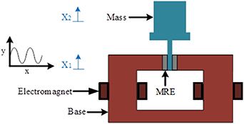
Figure 1. The diagrammatic sketch of an MRE-based isolator.
Download figure:
Standard image High-resolution imagewhere  represents the mass of the subject placed on the isolator and
  ,
,  and
and  are denoted as its displacement, velocity and acceleration, respectively.
  and
and  denote the displacement and velocity of the base excitation, respectively.
  and
and  are the equivalent field-dependent stiffness and damping of the MRE layers, respectively. Considering that the actuation force can be activated by shifting the stiffness and damping of the MRE, the governing equations of the MRE-based isolator can be written as [25]:


where  and
and  are the increased stiffness and damping of MRE layers induced by the increase of magnetic flux density, respectively;
  is the actuation or transmitted force through the MRE layers;
  and
and  are the minimum stiffness and damping of the MRE layers in the absence of applied magnetic induction field; while
  and
and  are the maximum stiffness and damping of the MRE layers corresponding to the maximum magnetic induction.
The relation between the stiffness of the MRE layers and its storage modulus can be described as [17, 26]:
and the relation between damping of the MRE layers and its loss modulus can be obtained as:
where  , A and ω are denoted as the equivalent thickness and area of the two MRE layers and the frequency of the base excitation, respectively. The experimental data of the MRE's storage and loss modulus and their curving fitting results are shown in figure 2. It is noted that the corresponding fabrication and characterization process of the MRE samples (made of Ecoflex 0020—smooth on as the matrix and 25% volume fraction of magnetic carbonyl iron particles) can be found in our previous studies [22]. Considering figure 2, a linear relation between storage and loss moduli and the applied magnetic flux density
  , may be presented (up to the applied magnetic flux density of 0.8 T) as:


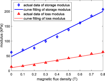
Figure 2. The experimental data of storage and loss modulus and their curving fitting results with respect to the applied magnetics density.
Download figure:
Standard image High-resolution imagewhere  and
and  are the storage and loss moduli in kPa, and
  is the applied magnetic flux density in T. It should be noted that results in figure 2 suggest that the storage and loss moduli are basically in linear relation with respect to the applied magnetic density in the range of 0.0 T–0.8 T. However, due to the magnetic saturation of carbonyl iron particles in MRE under high magnetic field, there would not be a significant change in moduli under magnetic flux density beyond 0.8 T and typically saturation occurs at magnetic flux densities around 1 T. Thus, the rate of increase of storage and loss moduli weakens under the increase of applied magnetic density beyond 0.8 T. It is noted that to reach the magnetic density beyond 0.8 T, relatively large current and power are required (heating up the electromagnet under long operation) and generally is impractical in the engineering application. Similarly, a linear relation between storage modulus and the loss moduli as plotted in figure 3 can be described as:


Figure 3. The loss modulus with respect to the storage modulus and its corresponding curve fitting result.
Download figure:
Standard image High-resolution imagewhere curve fitting parameters are identified through linear least-square optimization process as  ,
,  ,
,  ,
,  ,
,  and ζ = −5.63.
Now, by substituting equations (4)–(7) into equation (3), the actuation force of MREs can be rewritten as:
where  and are denoted as the minimum storage and loss moduli with the applying magnetic flux density being zero, respectively. It should be noted that using equations (8) and (9), we have
  and
and  . Considering this and substituting equations (8) and (9) into equation (11), the actuation force can be obtained as:
It should be noted that in the practical engineering, the electrical control system is treated as a discrete system. Hence, the system states of  ,
,  ,
,  ,
,  and the base excitation frequency
  can be considered as constants in a sampling period. Herein, we define the following:
where  is regarded as a constant in a sampling period and noting that
  . Thus, the minimum and maximum actuation force can be presented as:
The actuation force range of the MRE-based isolator can be further determined as:

Herein, it can be concluded that the actuation force is subject to dynamic saturation, and is coupled with the applied magnetic flux density, geometry of the MRE blocks, viscoelastic properties of MRE and system states. In order to demonstrate the effect of the dynamic input saturation, the actuation forces with the maximum magnetic flux density of 0.8 T and PD control under the dynamic input saturation are plotted in figure 4 (for related parameters with respect to MRE-based isolator and test conditions, please refer to PD control and random base excitation in section 4—simulation). The active control strategy (mostly using electric motor) possesses sufficient actuation force, but the MRE-based controlled system is subject to the inherent dynamic input saturation that severely limits the actuation force of the MRE-based isolator, and such a nonlinear behavior should be properly handled in the control law to ensure the effectiveness of the MRE-based isolator.
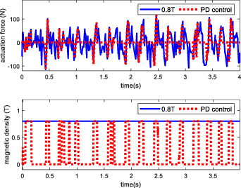
Figure 4. The actuation forces and its corresponding magnetic flux densities with passive control using the maximum magnetic flux density of 0.8 T and the PD control under the dynamic input saturation.
Download figure:
Standard image High-resolution image3. Development of the SC strategy
Considering that the dynamic input saturation of MRE-based isolator seriously restricts the actuation force, a novel SC, which adopts the fastest convergence speed of driving the virtual energy toward zero on the basis of Lyapunov theory, is proposed to improve the mitigation performance of the MRE-based isolator. The virtual energy is constructed with respect to the vibration displacement of the isolator, which is chosen as:
It is implied that by reducing the virtual energy, the vibration displacement of the isolator is alleviated. Taking the derivative of the virtual energy, the energy convergence speed can be obtained as:

Substituting  from equation (1) into equation (18) yields:
Substituting equations (6) and (7) into equation (19), it arrives:
Also, by substituting equation (10) into equation (20), and after simplification, it can be obtained:
Defining the following:
and then substituting equations (22) and (23) into equation (21), we can write:
Finally, substituting equation (8) into equation (24), the function of energy convergence speed with respect to the input (magnetic flux density,  ) can be derived as:
Derivative of equation (25) with respective to the magnetic flux density input yields:
It should be noted that in a sampling period,  and σ are constants, then it can be stated that
  is a monotonic function, whose monotonicity is determined by the term
  σ. The negative value of
  σ in equation (26) indicates a growth of the virtual energy; while the positive value of the
  σ implicates a decrease of the virtual energy. Herein, the fastest convergence speed of driving the virtual energy toward zero is adopted, which takes place when
  is the minimum. The monotonicity of
  indicates that the minimum of
  occurs in presence of the maximum applied magnetic flux density or the minimum applied magnetic flux density. This can be mathematically described as:

Therefore, the proposed control law that gives the minimum of  can be designed as:
According to the proposed SC, the control input switches between the maximum and minimum of the applied magnetic flux density to achieve the fastest convergence speed of driving the virtual energy toward zero on the basis of Lyapunov theory. It is worth noting that the proposed SC strategy is unsuitable for the active control strategy possessing sufficient actuation force, as a fast switching of the large control input may lead to a serious chattering of the control actuator. It can be observed in equation (19) that the term,  , is isolated from the magnetic field related parameters,
  and
and  . Thus, the term,
  does not affect the control input,
  . Hence the proposed control law can simply be represented as:
The proposed control law does not require the accurate mapping relationship between the applied magnetic density and MREs' stiffness and damping, instead, it only requires the values of MRE's stiffness and damping under the minimum and maximum magnetic density. It should be noted that the mapping relation between the applied magnetic density and MREs' stiffness and damping is very difficult to be accurately obtained in practical application, and its inaccuracy would considerably affect the performance of the control law designed on the basis of the mapping relationship. Therefore, the proposed control law is easier to be applied in practical application than the control schemes requiring the mapping relationship and has a more robust performance. Additionally, the proposed control scheme does not require a time-consuming adjustment of control parameters, thereby possessing the advantage of easy application.
4. Simulation
In this section, the performances of MRE-based isolator using various control schemes under the random external excitation, harmonic and bump shock excitation are investigated for the MRE-based isolator to compare and validate the effectiveness of the proposed control strategy for vibration isolation. The related parameters for the MRE-based isolator are provided in table 1, in which the minimum and maximum of the storage and loss moduli are obtained from experimental data, as shown in figure 2. It is noted that the minimum and maximum of the stiffness and damping properties of the MRE-based isolator are obtained by using equations (6) and (7).
Table 1. Assigned parameters for the MRE-based isolator.

| 4 (cm2) | Equivalent area of MREs |

| 2 (mm) | Equivalent thickness of MREs |

| 30 kg | The active mass |

| 0 (T) | Minimum magnetic flux density |

| 0.8 (T) | Maximum magnetic flux density |

| 47.79 (kPa) | Minimum storage modulus |

| 200.02 (kPa) | Maximum storage modulus |

| 10.10 (kPa) | Minimum loss modulus |

| 60.66 (kPa) | Maximum loss modulus |
4.1. Control schemes development
In this section, various control schemes including ON–OFF control, PD control and passive control using different constant magnetic field densities are formulated. It is noted that the control inputs of the applied magnetic field density using the proposed control, ON–OFF control and PD control are obtained using the control laws shown in equations (29)–(31), respectively, and their corresponding actuation forces are obtained using equation (12).
4.1.1. Passive control.
The stiffness and damping of the MRE-based isolator using passive control strategy are considered as constant, and different levels of magnetic field density corresponding to different values of stiffness and damping are adopted in the comparison. It is noted that the MRE actuating force in the absence of the applied magnetic flux density is zero, while it varies in the presence of the constant applied magnetic flux density owing to the fact that the MRE actuation force is also coupled with the variables of system states as it can be realized from equation (12). It is well-known that a significant vibration amplification of the MRE-based isolator using passive control strategy occurs when the frequency of base excitation is close to the resonance frequency.
4.1.2. ON–OFF control.
The ON–OFF or skyhook control is the most popular control scheme used in semi-active suspension, owing to its simple control law design and significant performance in resonance alleviation. The ON–OFF control law can be described as:
The logic of the ON–OFF control used in semi-active suspension is that when the velocity of the active mass has the same sign with the relative velocity between the active mass and base excitation, it is assumed that the actuation force produced by the MREs is hindering the locomotion of the mass away from the equilibrium state [27]. Hence the maximum magnetic density is applied to achieve the maximum damping. Otherwise, the minimum magnetic density is chosen. ON–OFF control only possesses the maximum or the minimum control input to perform.
4.1.3. PD control.
The proportional-derivative control, known as PD control, is widely used in the practical application of closed-loop control systems. In presence of the external disturbance and nonlinear dynamic behavior of the controlled system, the control performance of PD is prone to be unstable. Additionally, different proportional and derivative gains make different control performances, hence it normally requires trial and error to select the appropriate proportional and derivative gains to ensure an effective control performance. Considering the constraint of the applied magnetic flux density, the PD control law is presented as:
where the  and
and  are the proportional and derivative gains, respectively.
4.2. Random base excitation
The displacement profile and the power density spectrum (PDS) of the random excitation shown in figure 5 were provided at the base of the MRE-based isolator to compare its vibration isolation performance using various control schemes. The passive control using constant magnetic flux densities of 0 T, 0.4 T and 0.8 T was used for the control performance comparison. Considering that different proportional and derivative gains make different performances of the controlled system using PD control, a traversal method was adopted to select the proportional and derivative gains with the lowest RMS value of the isolator displacement  under the random base excitation. The initial proportional and derivative gains were both set at 100, and then 10 was added to the gains in each iteration, until their values reach 800, respectively. The RMS values of the isolator displacement
  using PD control with different proportional and differential gains are shown in figure 6. The proportional gain
  = 770 and differential gain
  = 240, which achieve the least RMS value, are selected for further control performance comparison.
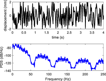
Figure 5. The displacement profile and PDS of the random excitation provided at the base of the MRE-based isolator.
Download figure:
Standard image High-resolution image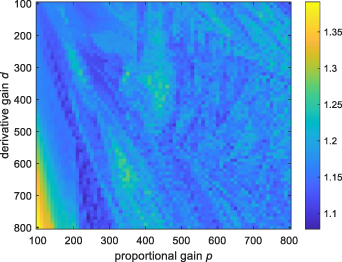
Figure 6. RMS values of the isolator displacement with respect to different proportional and derivative gains.
Download figure:
Standard image High-resolution imageThe actuation force and its corresponding magnetic flux density with ON–OFF control, PD control and SC control under the random base excitation are presented in figures 7 and 8. It can be realized in figure 8 that the applied magnetic flux density using the proposed SC strategy shares the similarity with the ON–OFF control in which they only have the maximum and minimum values to operate. As for the PD control, even though its magnetic flux density input can be presented in a continuous form, but due to the severe constraint on the control input, its magnetic flux density input switches between the maximum and minimum values most of the time. The displacement and acceleration responses of the MRE-based vibration isolator using various control schemes are provided in figures 9 and 10, respectively, and their RMS values of the displacement and acceleration under random excitation are provided in table 2. Results clearly show a superior control performance of the SC scheme over the ON–OFF control, passive control and PD control schemes on mitigation of the transmitted vibration.
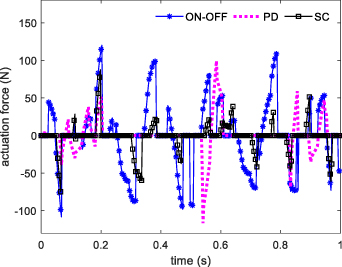
Figure 7. The actuation force of the isolator with ON–OFF, PD and SC control under the random base excitation.
Download figure:
Standard image High-resolution image
Figure 8. The output of magnetic flux density with ON–OFF, PD and SC control under the random base excitation.
Download figure:
Standard image High-resolution image
Figure 9. Displacement responses of the isolator mass using various control schemes under the random base excitation.
Download figure:
Standard image High-resolution image
Figure 10. Acceleration responses of the isolator mass using various control schemes under the random base excitation.
Download figure:
Standard image High-resolution imageTable 2. The performances comparison of the MRE-based isolator mass using various control schemes under random base excitation.
| Control scheme | RMS of  (mm) (mm) | RMS of  (m s−2) (m s−2) |
|---|---|---|
| Passive (0.0 T) | 1.38 | 0.44 |
| Passive (0.4 T) | 1.08 | 1.18 |
| Passive (0.8 T) | 1.14 | 1.86 |
| ON–OFF | 0.90 | 1.22 |
| PD | 0.84 | 1.05 |
| SC | 0.60 | 0.71 |
4.3. Harmonic base excitation
The performances of the MRE-based isolator using various controllers under harmonic base excitation are further investigated. The frequency of harmonic base excitation ranges from 0.5 Hz to 10 Hz, which covers the resonance frequency range of the MRE-based isolator by applying the magnetic flux density in the range of 0.0 T–0.8 T. The amplitude of the harmonic excitation is fixed at 2 mm. The proportional and differential gains are chosen as the same as in the case of random base excitation. The RMS values of the isolator's displacement and acceleration transmissibility using various control schemes with respect to different excitation frequencies of the harmonic base excitation are plotted in figures 11 and 12, respectively. Results show a significant vibration amplification of the MRE-based isolator using passive control in the resonance frequency range. While the ON–OFF control can effectively isolate the vibration in the resonance frequency range, but it widens the resonance frequency range and shows poor vibration isolation performance, particularly at the frequency range above 3.5 Hz. The PD control also does not perform well to isolate the vibration due to the poor selected proportional and differential gains, and it significantly amplifies the vibration around the excitation frequency of 4 Hz. The proposed SC strategy, however, demonstrates an excellent isolation capability both in resonance and non-resonance frequency region (wide range of frequencies) over the passive, ON–OFF and PD control schemes. To compare quantitatively, the peak RMS values (RMS values at the resonance frequency) of displacement and acceleration transmissibility of the MRE-based isolator with various control schemes are provided in table 3, in which the superiority of the proposed SC in vibration isolation of MRE-based isolator under the harmonic base excitation is clearly demonstrated.
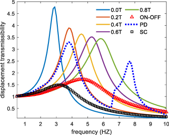
Figure 11. The RMS values of the isolator's displacement transmissibility using various control schemes with respect to different excitation frequencies of the harmonic base excitation.
Download figure:
Standard image High-resolution image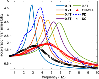
Figure 12. The RMS values of the isolator's acceleration transmissibility using various control schemes with respect to different excitation frequencies of the harmonic base excitation.
Download figure:
Standard image High-resolution imageTable 3. The performances comparison of the peak RMS values of MRE based isolator mass using various control scheme under the harmonic base excitation.
| Control scheme | Displacement transmissibility | Acceleration transmissibility |
|---|---|---|
| Passive (0.0 T) | 4.7 | 4.7 |
| Passive (0.2 T) | 3.9 | 3.9 |
| Passive (0.4 T) | 3.6 | 3.6 |
| Passive (0.6 T) | 3.5 | 3.5 |
| Passive (0.8 T) | 3.4 | 3.4 |
| ON–OFF | 1.7 | 1.9 |
| PD | 3.3 | 4.6 |
| SC | 1.5 | 1.8 |
4.4. Bump shock base excitation
In this section, the control performances of the MRE-based isolator using various controllers under a bump shock excitation are presented. The provided bump shock excitation is described as:
where wb = 20, and  = 2 mm is the height of the bump. The displacement and acceleration responses of the bump and the isolator using various controllers under the bump shock excitation are provided in figures 13 and 14, respectively. Results clearly show that the amplitude of the MRE-based isolator using the proposed SC controller converges to the neighborhood of zero faster than PD, ON–OFF and passive controller with the maximum and minimum magnetic flux density. The actuation force of the isolator and its corresponding magnetic flux density using ON–OFF, PD and SC controller under the bump shock excitation are also presented in figures 15 and 16. The RMS values of displacement and acceleration of the MRE-based isolator mass using various control schemes are provided in table 4 for the quantitative comparison. Results suggest the superior vibration mitigation of the MRE-based isolator using SC control under the bump shock base excitation.
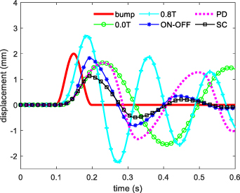
Figure 13. Displacement responses of the isolator using various control schemes under the bump shock.
Download figure:
Standard image High-resolution image
Figure 14. Acceleration responses of the isolator using various control schemes under the bump shock.
Download figure:
Standard image High-resolution image
Figure 15. The actuation force of the isolator with ON–OFF, PD and SC controller under the bump shock excitation.
Download figure:
Standard image High-resolution image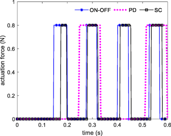
Figure 16. The magnetic density output of the isolator with ON–OFF, PD and SC controller under the bump shock excitation.
Download figure:
Standard image High-resolution image
Table 4. The performances comparison of the MRE based isolator mass using various control scheme under the bump shock excitation.
| Control scheme | RMS of  (mm) (mm) | RMS of  (m s−2) (m s−2) |
|---|---|---|
| Passive (0.0 T) | 0.98 | 0.33 |
| Passive (0.8 T) | 1.21 | 1.58 |
| ON–OFF | 0.64 | 0.62 |
| PD | 0.88 | 0.72 |
| SC | 0.41 | 0.33 |
5. Concluding remarks
In this study, the governing dynamic equations of the MRE-based isolator were established using the experimental data. The actuation force of the MRE-based isolator is subject to dynamic saturation, and is coupled with the applied magnetic flux density, geometry of the adopted MRE blocks, viscoelastic properties of MRE and system states. A mathematical proof has been provided to prove that the fastest convergence speed takes place in presence of the minimum or maximum of the applied magnetic flux density. Subsequently, a novel SC strategy was proposed to improve the mitigation performance of the MRE based isolator. Eventually, the vibration isolation performance of the MRE-based isolator using the proposed control strategy was compared with those based on passive control in presence of different levels of magnetic field density, ON–OFF control and PD control under the harmonic, random and bump shock base excitations. The results showed the robust and superior performance of the proposed control strategy. The superior performance of the proposed SC strategy may be attributed to its inherent control logic, in which the fastest convergence speed of driving the convergence speed of virtual energy toward zero is adopted as so to fully take advantage of the actuation force to mitigate the unwanted vibration.
Acknowledgments
Supports from the Natural Sciences and Engineering Research Council of Canada (NSERC), Science and technology bureau of Guangdong Province Grant (2018A050501010) and Shenzhen Science and Technology for International Cooperation Research Program (GJHZ20190821155201661) are gratefully acknowledged.
Data availability statement
The data that support the findings of this study are available upon reasonable request from the authors.