the Creative Commons Attribution 4.0 License.
the Creative Commons Attribution 4.0 License.
 | 04 Aug 2021
Thick- and thin-skinned basin inversion in the Danish Central Graben, North Sea – the role of deep evaporites and basement kinematics
Torsten Hundebøl Hansen
Ole Rønø Clausen
Katrine Juul Andresen
Using borehole-constrained 3D reflection seismic data, we analyse the importance of sub-salt, salt, and supra-salt deformation in controlling the geometries and the kinematics of inverted structures in the Danish Central Graben. The Danish Central Graben is part of the failed Late Jurassic North Sea rift. Later tectonic shortening caused mild basin inversion during the Late Cretaceous and Paleogene. Where mobile Zechstein evaporites are present, they have played a significant role in the structural evolution of the Danish Central Graben since the Triassic. Within the study area, Jurassic rifting generated two major W- to SW-dipping basement faults (the Coffee Soil Fault and the Gorm–Tyra Fault) with several kilometres of normal offset and associated block rotation. The Coffee Soil Fault system delineates the eastern boundary of the rift basins, and within its hanging wall a broad zone is characterized by late Mesozoic to early Paleogene shortening and relative uplift. Buttressed growth folds in the immediate hanging wall of the Coffee Soil Fault indicate thick-skinned inversion, i.e. coupled deformation between the basement and cover units. The western boundary of the inverted zone follows the westward pinch-out of the Zechstein salt. Here, thin-skinned folds and faults sole out into Zechstein units dipping into the half-graben. The most pronounced inversion structures occur directly above and in prolongation of salt anticlines and rollers that localized shortening in the cover above. With no physical links to underlying basement faults (if present), we balance thin-skinned shortening to the sub-salt basement via a triangle zone concept. This implies that thin Zechstein units on the dipping half-graben floor formed thrust detachments during inversion while basement shortening was mainly accommodated by reactivation of the major rift faults further east. Disseminated deformation (i.e. “ductile” at seismic scales) accounts for thin-skinned shortening of the cover units where such a detachment did not develop. The observed structural styles are discussed in relation to those found in other inverted basins in the North Sea Basin and to those produced from physical model experiments. Our results indicate that Zechstein units imposed a strong control on structural styles and kinematics not only during rift-related extension but also during basin inversion in large parts of the Danish Central Graben. Reactivated thin-skinned faults soling out into thin Triassic evaporite units within the carapace above Zechstein salt structures illustrate that even thin evaporite units may contribute to defining structures during tectonic extension and shortening. We thus provide an updated and dedicated case study of post-rift basin inversion, which takes into account the mechanical heterogeneity of sub-salt basement, salt, and supra-salt cover, including multiple evaporite units of which the Zechstein is the most important.
- Article
(72904 KB) - Full-text XML
- BibTeX
- EndNote


1.1 Basin inversion and the role of mobile evaporites
Basin inversion is a fundamental process in the tectonic evolution of sedimentary basins. It may play an important role in the formation of hydrocarbon traps, although it can also have negative effects on the prospectivity of a basin (Turner and Williams, 2004). Many authors have reviewed the concept of basin inversion and the criteria for recognizing the resulting structures (see, e.g. Cooper et al., 1989; Coward et al., 1991; Eisenstadt and Withjack, 1995; Coward, 1996; Kockel, 2003). Mild inversion refers to a small magnitude of shortening relative to the magnitude of earlier extension (Cooper et al., 1989). In this study, we define basin inversion as the shortening of previously extensional basins due to compression or transpression (see Cooper et al., 1989; Turner and Williams, 2004). From here, our use of the term “inversion” refers to basin inversion, unless specifically stated otherwise. Inversion is recognizable from the structures that accommodate shortening and uplift of the basin packages: reverse reactivation of pre-existing normal faults or fault trends, i.e. fault inversion, and the development of shortcut thrusts and folds (e.g. Williams et al., 1989; Turner and Williams, 2004). In recent years, the increased prevalence of borehole-constrained 3D seismic data of high quality has improved our understanding of inversion structures and their development, especially in basins that are only mildly inverted (e.g. Jackson and Larsen, 2008; Grimaldi and Dorobek, 2011; Jackson et al., 2013). Mild inversion is advantageous to such studies because pre-existing structures are still well resolved, making their role during inversion easier to delineate (Jackson et al., 2013).
Several physical model studies have illustrated the structural styles and development of inversion structures (e.g. Koopman et al., 1987; McClay, 1989, 1995; Eisenstadt and Withjack, 1995; Brun and Nalpas, 1996; Bonini et al., 2012; Jagger and McClay, 2018; Dooley and Hudec, 2020), as well as how initial three-dimensional geometries of normal faults affect the development of inversion structures (e.g. Yamada and McClay, 2004). Depending on the reactivation of basement faults below the basin fill, the effects of inversion may vary a great deal between different parts of the extensional basin. Basement faults are more prone to reactivate in a reverse sense with gentle dip angles, oblique angles between their strike and the direction of shortening, low frictional resistances along fault planes, and high connectivity to fluids expelled from juxtaposed rocks (Bonini et al., 2012). Forced folding and short-cut structures tend to occur where the strikes of inherited extensional structures are approximately orthogonal to the direction of maximum compressive stresses, and where steeply dipping normal faults bound the basin (Letouzey, 1990). If instead the incidence is oblique, a strike-slip component is induced that allows for reactivation of steeply dipping faults (Letouzey, 1990; Letouzey et al., 1990).
Additionally, workers have utilized physical models to investigate the structures formed by extension (e.g. Withjack and Callaway, 2000; Ferrer et al., 2017) and inversion of rift basins containing weak evaporite sequences (e.g. Nalpas et al., 1995; Brun and Nalpas, 1996; Bonini et al., 2012; Roma et al., 2018a, b; Ferrer et al., 2017). These have shown that mobile evaporites can play a major role in the structural development of basins during both extension and inversion, due to their ability to decouple deformation (partially or fully) in the substrata and overburden. The model studies of Letouzey et al. (1995) showed that major controlling factors on the localization of reverse faulting and folding in inverted graben include pre-existing extensional structures, salt thickness, and the distribution of older evaporite structures. Following salt deposition, salt ridges tend to form when extension causes salt to flow up-dip on the hanging wall floor away from the main fault because of the deformation of the sub-salt hanging wall and the increased sediment load just adjacent to the main fault (Vendeville, 1987; Vendeville and Jackson, 1992; Nalpas and Brun, 1993). During subsequent shortening and inversion, folding and reverse faulting or thrusting will often initiate above salt ridges with favourable orientations, where the overburden is thinned and possibly faulted. This occurs even when there is no direct link to basement faults (Letouzey et al., 1995; see also Brun and Nalpas, 1996).
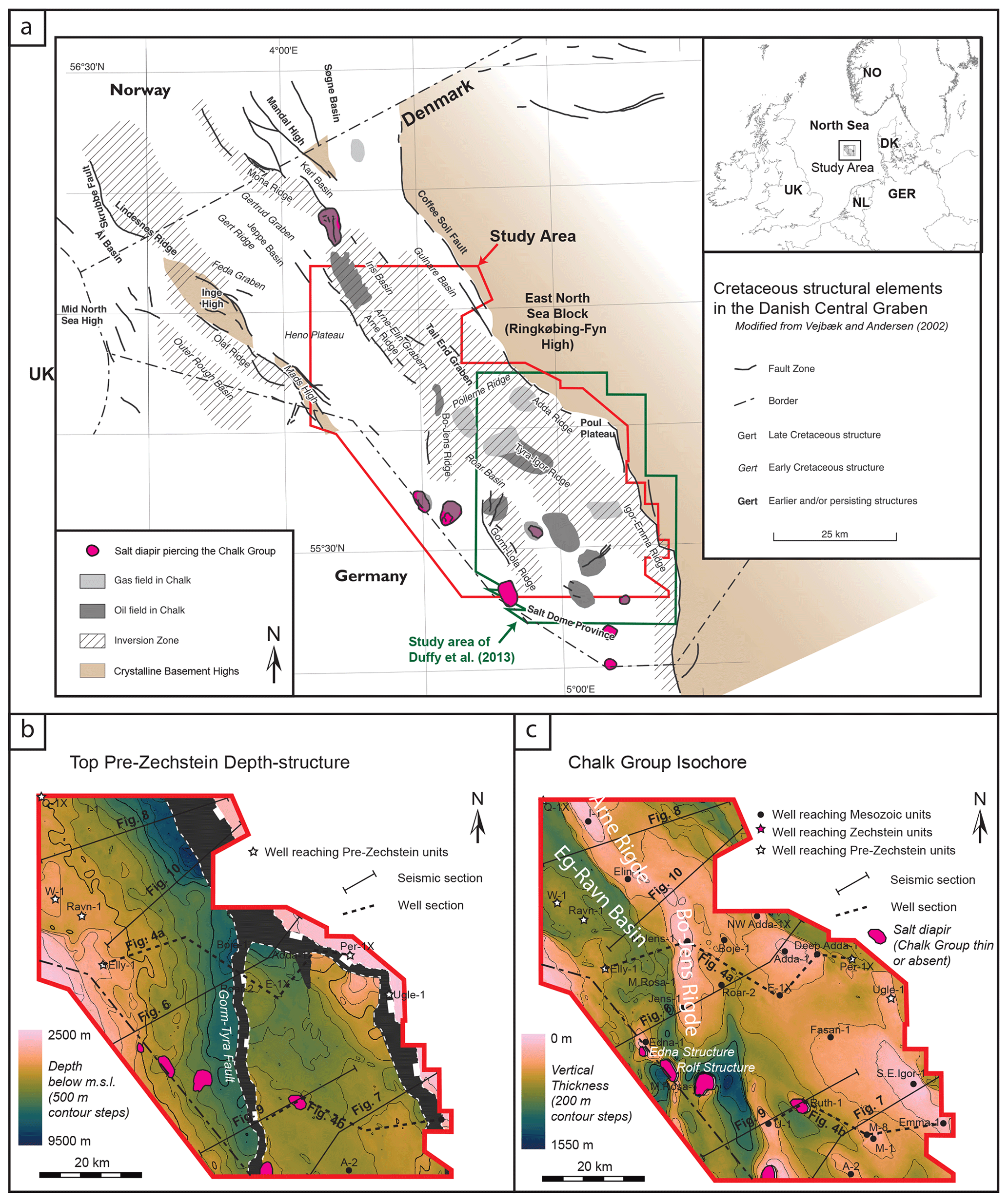
Figure 1(a) The map shows the Danish Central Graben with Cretaceous structural elements, as well as the inverted areas and the position of the study area in the uppermost right corner. The oil and gas fields in the Danish Sector, as well as salt structures piercing the Chalk Group, are shown for reference. The outline of the study area covered by the used seismic data (red) and the outline of the study area (green) of Duffy et al. (2013) are indicated. (b) The map shows the topography of the Top pre-Zechstein surface in the studied area including the major faults for reference. Wells penetrating the surface, as well as the interpreted seismic sections, and the well sections presented here are indicated. (c) The map shows an isochore map of the Late Cretaceous to Danian Chalk Group with indications of the major structural elements (ridges and basins) for reference. The outline of the Danish Central Graben as imaged on the Top pre-Zechstein surface is reflected in the isochore map of the Chalk Group, but the latter is much more complicated as consequence of the mobile Zechstein salt, which decouples deformation and initiates local subsidence, etc. The understanding of this difference is one of the goals of our study. The colour scale used (Batlow) was constructed by Crameri (2018).
1.2 Study aims
Along with salt diapirism, basin inversion is responsible for a significant number of structural traps for hydrocarbon reservoirs in Cretaceous Chalks in the Danish Central Graben (Megson, 1992; Vejbæk and Andersen, 2002). The deformational histories and geometries of these reservoir strata are closely related to basin inversion that occurred mainly in the Late Cretaceous, when they were buried only at shallow depths or were still being deposited (Vejbæk and Andersen, 1987; Cartwright, 1989; Vejbæk and Andersen, 2002). Duffy et al. (2013) analysed the controls of mobile evaporites on the structural development during Triassic and Jurassic rifting in a smaller part of the Danish Central Graben (hereafter DCG; Fig. 1). Their work highlights the DCG as a well-suited area for studying the structural controls of deep evaporites, as the thickness of the Zechstein units here range from near zero in some areas to thousands of metres in salt structures. In addition, the combination of a mild yet significant degree of inversion and the well-preserved extensional fabric provides an excellent opportunity to link the kinematics of inversion structures formed near the surface to deeper inherited structures and evaporites. This is the focus of the present study. We provide an updated kinematic analysis of a portion of the DCG (Fig. 1) in order to explain the role of mobile evaporites and salt tectonics during Late Cretaceous basin inversion, and the relationship between deformation in the sub-salt basement and supra-salt overburden. So far, the studies dedicated to inversion in the DCG focused on spatial variations in timing of inversion (Vejbæk and Andersen, 1987, 2002; Cartwright, 1989) – we instead focus on the kinematic connections between the upper inversion structures, the Zechstein units and pre-Zechstein basement below. This revision is due as a wealth of general and conceptual knowledge has since then surfaced on extensional and compressional deformation of basins containing mobile evaporites (e.g. Vendeville and Jackson, 1992; Letouzey et al., 1995; Stewart and Clark, 1999; Withjack and Callaway, 2000; Bonini et al., 2012; Stewart, 2014). Our analysis incorporates these findings with our own results from seismic mapping and structural interpretation of a high-quality 3D seismic data set. The main objective of the present study is thus to relate and discuss our observations to published results about the following topics.
-
The controls of evaporites on inversion structures in the study area and mildly inverted basins in general.
-
The kinematics of basement shortening and basement fault inversion.
-
The magnitude and direction of shortening during inversion.
-
The mechanisms responsible for ductile deformation styles in the cover units.
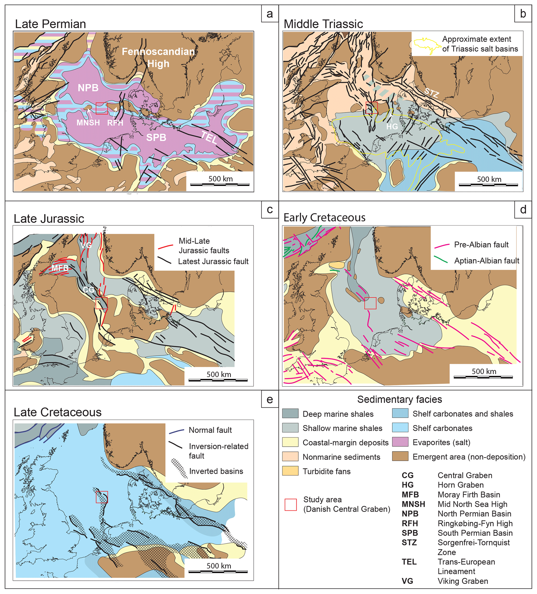
Figure 2Palinspastic maps of the North Sea region indicating the distribution of active large-scale structures and general sedimentary facies at different periods (modified from Ziegler, 1990, and Coward et al., 2003). Modern-day coastlines are shown for reference: (a) late Permian, (b) Middle Triassic, (c) Late Jurassic, (d) Early Cretaceous, and (e) Late Cretaceous. Indicated inverted areas are from Kley (2018).
2.1 Paleozoic
The North Sea area has accommodated sediments since Cambrian times while experiencing compressional, extensional, and inversion tectonic regimes (Ziegler, 1990; Vejbæk, 1997; Coward et al., 2003; Lassen and Thybo, 2012). The present outline of the North Sea Basin relates to an early Permian thermal event and crustal extension (Vejbæk, 1997; Glennie et al., 2003). Early Permian rifting involved widespread volcanism, fault block rotation, and erosion of footwall crests (Stemmerik et al., 2000; Mogensen and Korstgård, 2003; Coward et al., 2003; Glennie et al., 2003; Clausen et al., 2016). Post-rift thermal subsidence (sensu McKenzie, 1978) followed and formed the extensive Northern- and Southern Permian Basins separated by an approximately E–W-striking basement high, which would later separate into the Mid North Sea and Ringkøbing–Fyn highs (Vejbæk, 1990, 1997; Sørensen 1986). In late Permian times, the evaporites of the prominent Zechstein Group were deposited in these basins (Fig. 2a). These units pinch out towards the basin boundaries where marginal evaporite facies dominate while large volumes of halite formed in the basin centres (Stemmerik et al., 2000; Glennie et al., 2003). Inherited regional topography largely controlled the extent of the evaporites although rifting generated fault-controlled subsidence in, e.g. the Central Graben and Horn Graben areas, which allowed thicker packages to accumulate (Clausen and Korstgård, 1993b; Korstgård et al., 1993). Due to later halokinesis, it is unknown whether faulting occurred during or prior to evaporite deposition (e.g. Duffy et al., 2003).
2.2 Triassic and Jurassic
Triassic rifting in the central and southern North Sea area generated approximately N–S-striking faults as part of the development of the Central Graben and Horn Graben (Fig. 2b; Coward et al., 2003). The Mid North Sea and Ringkøbing–Fyn highs greatly influenced Triassic sedimentation, as evident from lithological differences in the two basins. Continental clastics with local and thin evaporite beds dominated to the south (Fig. 2b), while occasional marine transgressions from the Tethys introduced marine conditions and flooded the Mid North Sea High. The most northward extent of these marine transgressions occurred in the easternmost part of the North Sea Basin (Bertelsen, 1980; Michelsen and Clausen, 2002). The Triassic sediments in the Danish Central Graben show a close relationship to the area south of the Mid North Sea and Ringkøbing–Fyn highs (Michelsen and Clausen, 2002). At this time, halokinesis involving Zechstein units initiated, and differential subsidence due to halokinesis possibly controlled the distribution of fluvial sediments (Goldsmith et al., 2003; McKie et al., 2010; Jarsve et al., 2014).
The Jurassic was dominated by intense rifting, which highly influenced the Moray Firth, the Viking Graben, and the Central Graben (Fig. 2c). Thermal doming at the triple junction initiated in Early Jurassic times and erosion of older deposits generated the widespread and easily recognizable Mid Cimmerian Unconformity (Coward et al., 2003). Intense Late Jurassic rifting occurred over two main phases. The first reactivated N–S-striking normal faults during E–W-directed extension. In the Danish Central Graben, this generated mainly eastward-dipping half-grabens (Roberts et al., 1990). The second phase formed NNW–SSE-striking faults that connected the older faults. This combination caused a rather complex fault pattern in the Danish Central Graben. Thick syn-rift mudstone deposits of especially the Farsund Fm. provide good source rocks locally in the DCG (Michelsen et al., 2003).
2.3 Cretaceous and Cenozoic
Deposition of marine shales characterize the Early Cretaceous, while faulting gradually ceased in the central North Sea area (Fig. 2d; Coward et al., 2003) and post-rift thermal subsidence formed accommodation (Sclater and Christie, 1980). Extensive deposition of pelagic shelf carbonates followed in Late Cretaceous and Danian times, forming the Chalk Group, while siliciclastic units were restricted to the basin margins (Fig. 2e; Ziegler, 1990; Surlyk et al., 2003). Widespread Late Cretaceous and early Paloegene inversion tectonism in the Alpine foreland caused uplift and erosion of former depocentres, as well as re-deposition of sediments in the southern and central North Sea area (e.g. Ziegler, 1987; Kley, 2018). Inversion generated a significant number of structural traps for producing hydrocarbon reservoirs in, e.g. the Danish and Norwegian parts of the Central Graben (Damtoft et al., 1987). The post-Danian Paleogene was dominated by siliciclastic deposition from the emergent areas surrounding the North Sea basin, meaning that the deep basin above the Mesozoic rift system gradually filled (Gołedowski et al., 2012; Anell et al., 2012). Inversion activity in the North Sea Basin continued, although the activity migrated westwards relative to the areas affected in the Cretaceous and Paleogene (Ziegler, 1990; Kley, 2018).
Locally in the DCG, inversion movements may have initiated as early as in the late Hauterivian (Vejbæk, 1986). Although punctuated by pulses of increased activity, inversion was continuous in the DCG throughout the Late Cretaceous (Vejbæk and Andersen, 1987, 2002). Around the beginning of the Campanian, it became a major influence on the basin morphology, forming a prominent unconformity above earlier rift depocentres (van Buchem et al., 2018). The relative uplift caused by inversion occurred on a background of post-rift thermal subsidence and was small enough that erosion was limited in comparison to other inverted basins in the southern North Sea. Subsequent Paleogene inversion generated only a wide and gentle flexure above the rift (Fig. 1; Vejbæk and Andersen, 2002; Clausen and Korstgård, 1993a; Clausen et al., 2012).
3.1 Data
A regional merge of reprocessed data from several 3D reflection seismic surveys with a total area of ca. 6000 km2 was available for this study. This covers most of the DCG area. We used a sub-crop of this dataset with an area of ca. 4000 km2, covering parts of the Heno Plateau, Tail End Graben and Salt Dome Province areas (Fig. 1). The dataset is Kirchhoff pre-stack depth-migrated, has a 12.5 m inline (N–S direction) and crossline (E–W direction) spacing, and extends to a depth of 10 km. The vertical sampling rate is 4 ms, and the seismic wavelet is zero phase with European polarity. Therefore, in the seismic sections shown herein, a negative amplitude (trough) corresponds to a downward increase in acoustic impedance, i.e. a hard response. The velocity model applied for depth imaging is verified with check-shot data and sonic data from wells.
Within the Chalk Group, the vertical seismic resolution is ca. 25 m, i.e. a quarter of the wavelength of the dominant frequency. The signal quality is generally excellent, although it deteriorates close to and below large lateral discontinuities, e.g. salt diapirs, large faults, and sub-vertical strata. We chose to interpret depth-converted seismic data in order to avoid structural misinterpretations of apparent deformation caused by velocity variations, e.g. pull-up below salt structures. Approximately 25 exploration wells within the study area have been included with formation tops constrained by biostratigraphy (Nielsen and Japsen, 1991).
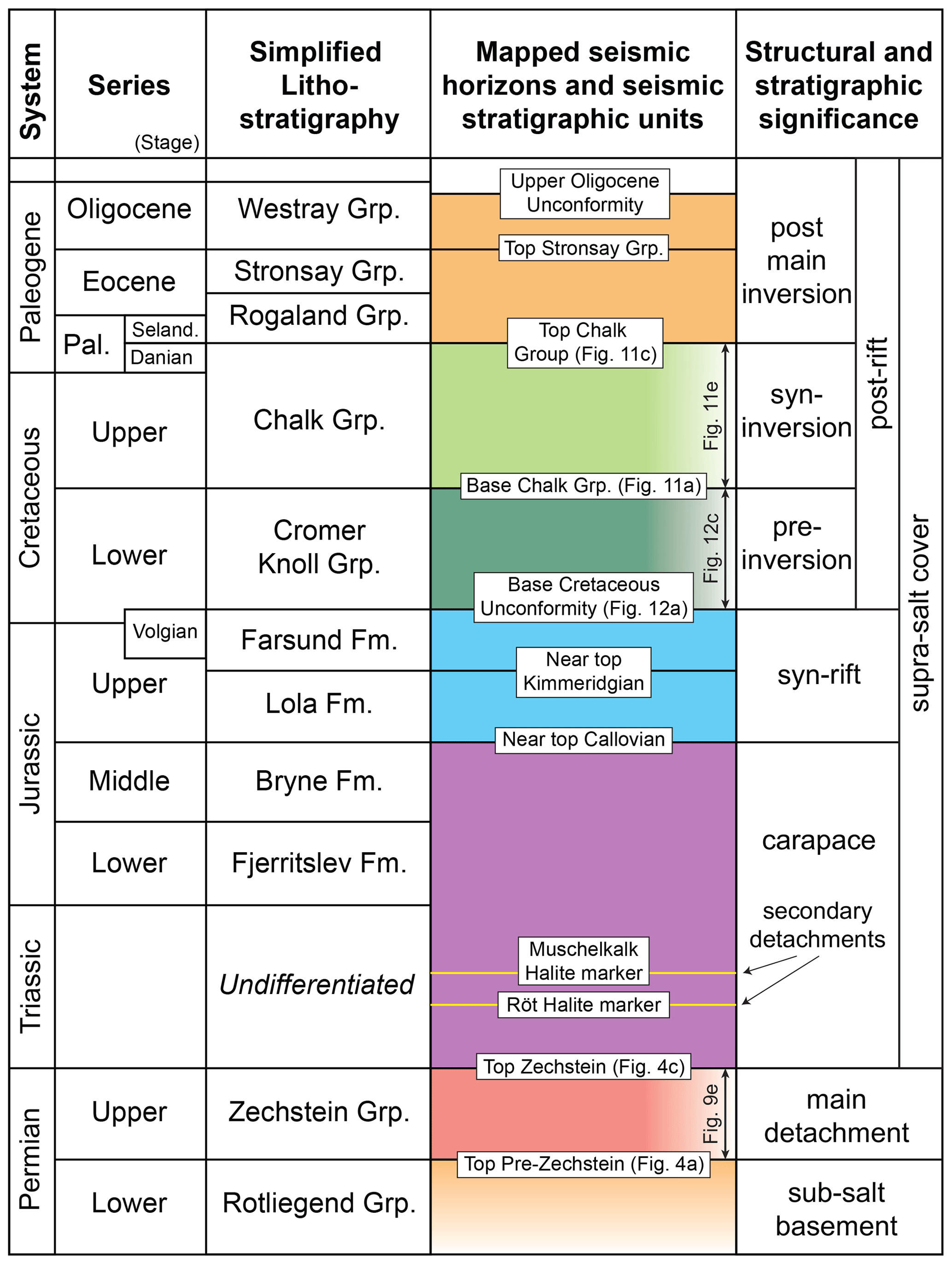
Figure 3Stratigraphic table indicating the seismic surfaces and stratigraphic units used for this study. Other figures presenting depth and isochore maps are referenced. In the rightmost column, the structural and stratigraphic significance of each unit is indicated. The simplified Jurassic lithostratigraphy is based on Michelsen et al. (2003) and the simplified Paleogene lithostratigraphy is based on Schiøler et al. (2007).
3.2 Methods
3.2.1 Seismic-stratigraphic analysis
The methods applied in this study follow common procedures applied in tectono-stratigraphic basin analyses from seismic data. Initially, relevant seismic surfaces were mapped (Fig. 3), along with prominent deformational features, i.e. faults, folds, and salt structures. Our seismic surfaces from Top pre-Zechstein to Top Chalk Group are equivalent to surfaces of the same names illustrated by van Buchem et al. (2018). The upper surfaces, Top Stronsey Group and Upper Oligocene Unconformity, are equivalent to those used by Clausen et al. (2012). Surfaces following continuous reflections of moderate to high amplitudes were favoured in order to make mapping across the study area easier with the aid of formation tops in wells. For mechano-stratigraphic purposes, we refer to all deposits above the Zechstein units as (supra-salt) cover and everything below, including non-crystalline deposits, as (sub-salt) basement (sensu Duffy et al., 2013).
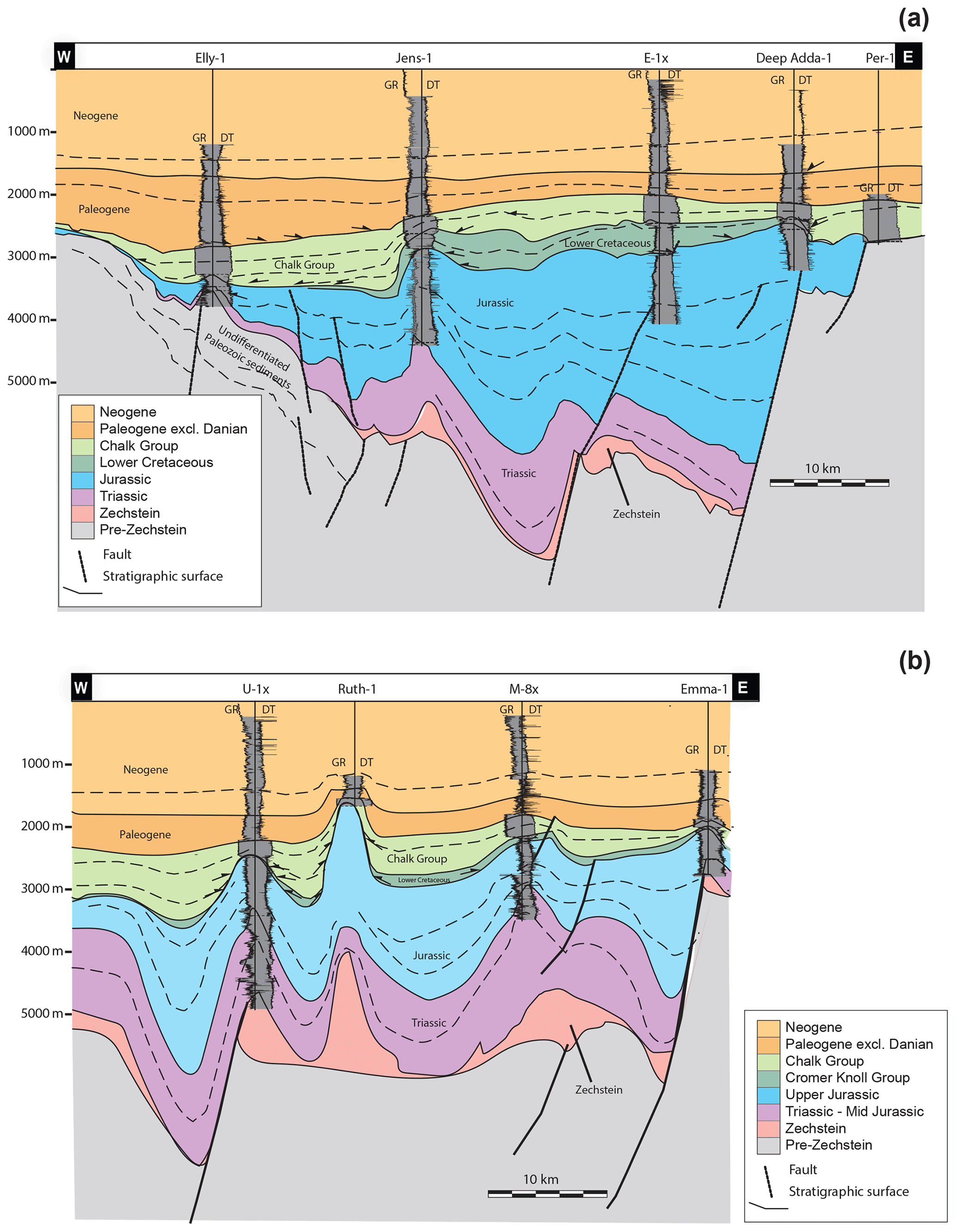
Figure 4The mapped horizons are tied to more than 25 exploration wells in the studied area. The position of the sections shown in panels (a) and (b) can be seen in Fig. 1. The lithologies in the wells are illustrated by means of the GR log and the DT log. Both sections emphasize the problem of most wells being drilled on the top of structures, which makes the pre-Jurassic stratigraphic interpretation (and thus structural timing) more difficult to constrain. The geometry of the horizons between the wells are given from the seismic interpretations (see text for further information).
Two W–E-striking well panels (Fig. 4) show the stratigraphic subdivision (based on petrophysical well logs and biostratigraphy) and the position of the mapped seismic surfaces. Only a few wells reach the basement in the study area, either on the Ringkøbing–Fyn High where the Cretaceous directly overlies crystalline basement or in the western part where Zechstein Group deposits are absent. Here, the Mesozoic overlies Lower Permian Rotliegend deposits. In addition, Zechstein evaporites are only reached by wells atop salt structures. We therefore mapped the top and base of the Zechstein Group away from these structures with the aid of seismic-facies analysis (see Duffy et al., 2013). The Zechstein salt is recognizable due to its chaotic seismic facies with low-amplitude and discontinuous reflections in contrast to the parallel and better-defined reflections of the deposits above and below.
Depth–structure maps were produced for the mapped surfaces to investigate the current structural configuration and in order to generate isochore maps (vertical thickness) for the Zechstein Group (Upper Permian), Cromer Knoll Group (Lower Cretaceous), Chalk Group (Upper Cretaceous and Danian), and Paleogene excl. Danian. We then analysed the isochore maps in order to identify differential subsidence caused by faulting, folding, or mobile-evaporite movements. This assumes that the observed differences in thickness are a proxy for subsidence variations due to these movements. However, differential compaction, water level, and sedimentary processes and supply also affect subsidence to a significant degree (see, e.g. Sclater and Christie, 1980; Bertram and Milton, 1989). Therefore, we integrated observations of stratal relationships to obtain a higher degree of certainty in the delineation of subsidence patterns and the reconstruction of past basin geometries.
The isochore maps presented later indicate structures that were active during the Cretaceous and Paleogene when basin inversion occurred, and these structures have been analysed. Based on observations of their geometries, magnitudes, and age relationships, these analyses include qualitative descriptions of the kinematics and the mechanics involved in generating these structures. We describe their kinematic relationships with deeper structures, especially Zechstein salt and basement faults, in order to infer the deformation of the deeper basin due to inversion.
3.2.2 Analysis of mobile-salt migration
In accordance with the assumptions and method of Duffy et al. (2013), we classify the Zechstein units as immobile in areas where their thickness is generally below 200 m and they are restricted to local topographical lows in the Top pre-Zechstein surface. Duffy et al. (2013) used <100 ms two-way travel time. This corresponds to 225 m, with a typical seismic velocity of 4500 m/s for halite. On this basis, we constructed a “mobile-salt pinch-out” to separate the present-day domains characterized by either immobile (thin) or potentially mobile Zechstein salt (thick; Fig. 5f).
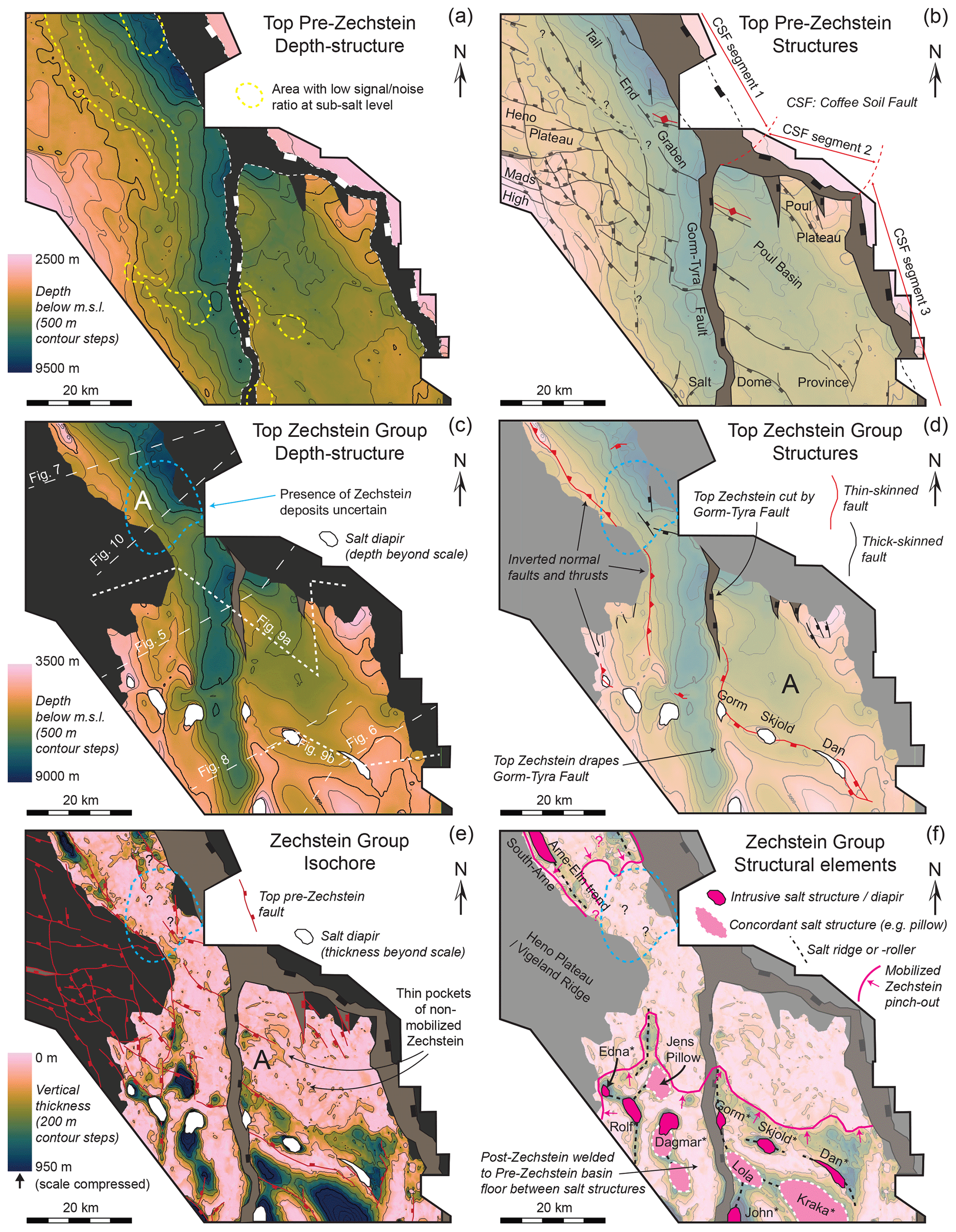
Figure 5Depth and structure maps constructed from seismic data illustrating the deformational geometries and extent of the sub-salt basement and the Zechstein (salt) units. In the Top-Pre Zechstein depth map (a), areas with a low signal/noise ratio are indicated by a dashed yellow line. In Top pre-Zechstein structures (b), all the names of the structures used in the text are indicated. The same counts for the Top Zechstein Group depth (c) and Top Zechstein Group structures (d). Note the distinction in (d) between thick-skinned faults that are linked between the cover and basement (black lines) and thin-skinned faults that sole out into Zechstein units (red lines). Within the area outlined in bright blue (marked as “A”) in (c), no wells penetrate to Zechstein levels, and the conspicuous contrast between the smooth Top-Zechstein reflection and the rugged Top pre-Zechstein reflection is not present as it is in other areas (compare with Figs. 9 and 10). If Zechstein units are present here, it may be only as a thin succession of marginal facies. (e) Zechstein Group isochore (thickness) map and (f) structural elements. Major mobile-salt structures are indicated, as well as the current-day pinch-out of mobilized Zechstein salt. An overview of the stratigraphic units and mapped surfaces is found in Fig. 3. The colour scale used (Batlow) was constructed by Crameri (2018).
Duffy et al. (2013) demonstrated that “tongues” of Zechstein units were initially present beyond the modern-day pinch-out of mobilized Zechstein east of the Gorm–Tyra Fault. These either dissolved or evacuated southward into the larger mobile-salt structures. Similar movements may have taken place in the hanging wall of the Gorm–Tyra Fault and in the Tail End Graben (for the location, see Fig. 1), where salt could have migrated towards areas of lower-pressure inversion. As mobile evaporites impose controls on deformation of the supra-salt succession (Stewart, 2007, 2014), the differences between the syn-inversion and modern-day distributions of mobile Zechstein units have significant implications for the kinematics of inversion. We have therefore included an analysis of the subsidence patterns of the Cromer Knoll Group (Early Cretaceous, pre-inversion) to aid in constraining the extent of the mobile Zechstein salt at the onset of inversion. Vejbæk (1986) indicated that halokinesis influenced the subsidence pattern during the Early Cretaceous, and it is possible that similar salt movements continued into the Late Cretaceous and modified some inversion structures. In our analyses, we have only considered the salt budget qualitatively, but based on the relatively small volumes of salt withdrawal inferred from local Cretaceous depocentres, we consider the continued growth of several large salt structures into even Neogene times as realistic. In addition, dissolution of salt from diapirs may have removed some amounts through time (Korstgård et al., 1993; Rank-Friend and Elders, 2004), but it is generally accepted that dissolution has only a minor impact on the salt budget (Jackson and Hudec, 2017).
In this chapter, we present findings from our analysis of the seismic data. We first describe the structures and geometries of the sub-salt basement and the Zechstein Group along with the current areal distribution of potentially mobile and non-mobile Zechstein units (Fig. 5). We then characterize the structural styles of inversion-related deformation during the Late Cretaceous. Finally, we infer the distribution and movements of mobile Zechstein units during Early and Late Cretaceous times, as these may have implications for the contemporary kinematics.
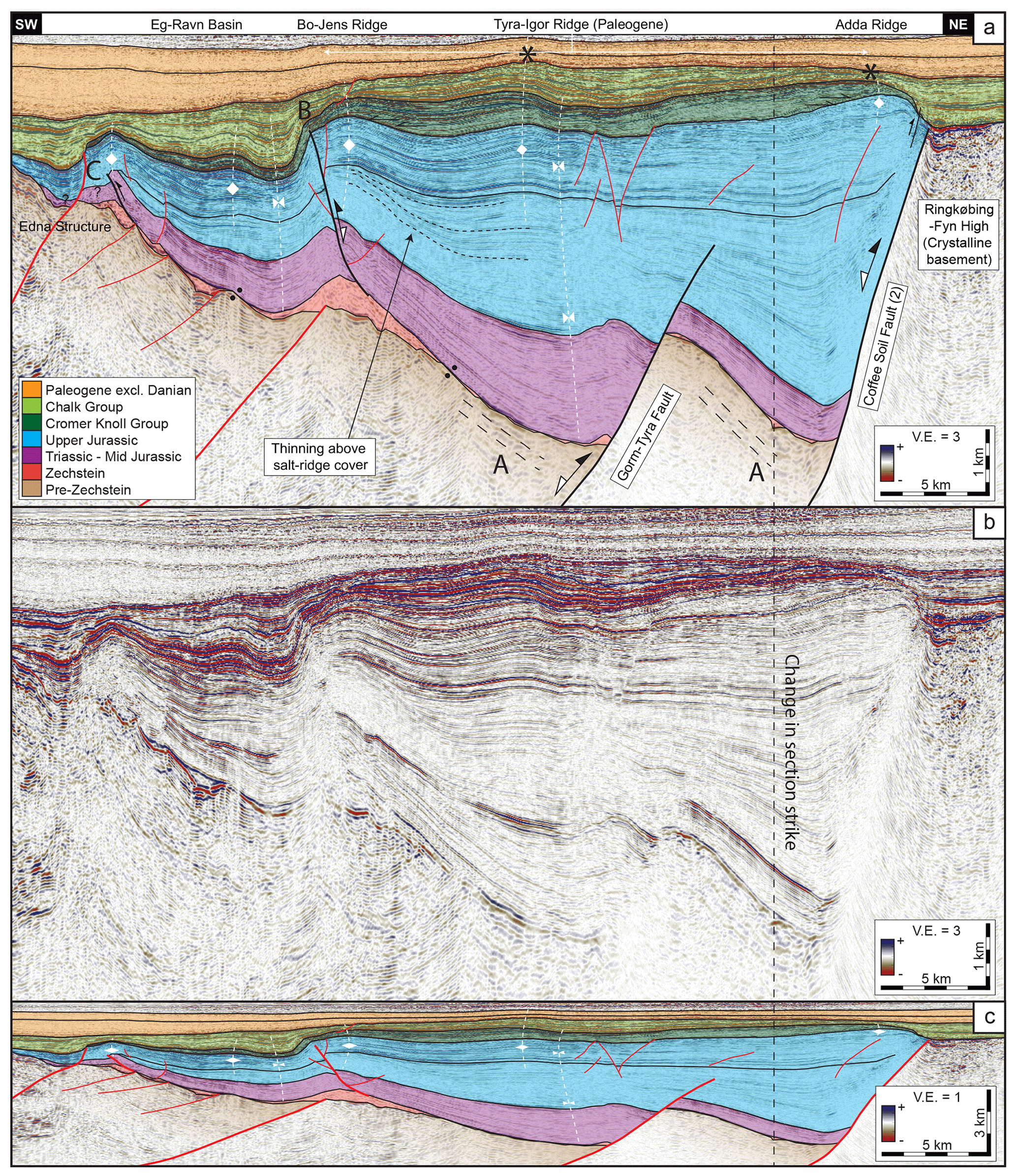
Figure 6(a) Interpreted seismic section across the Bo–Jens and Adda Ridges. The Tyra–Igor Ridge (Paleogene inversion) is also indicated. Note the thin-skinned structures detached by Zechstein units (marked as “B” and “C”) and a salt roller (Edna Structure) in the left portion of the section. Indicated synclines can be traced deep into the cover units (marked as “∗”). Suggested pre-Zechstein sediment layering across the Gorm–Tyra Fault is marked “A”. Named structures in the header and marked fold axes indicate Late Cretaceous topographical elements unless otherwise noted. See the text for further details. (b) Uninterpreted section. (c) Interpreted section with no vertical exaggeration. An overview of the stratigraphic units and mapped surfaces is found in Fig. 3. The location of the section is indicated in Figs. 1, 5, 12a, and 11c. Seismic data are supplied by DUC.
4.1 Sub-salt structures and geometry
Two major rift faults occur in the study area: the Coffee Soil Fault and the Gorm–Tyra Fault (Figs. 1, 6). The overall structural architecture of the pre-Cretaceous in the study area approximates that of a NW–SE-trending half-graben bounded by the Coffee Soil Fault (Fig. 6) (Gowers and Sæbøe, 1985; Cartwright, 1991). This major structure constitutes the master rift fault along the northeastern boundary of the Central Graben throughout the Danish North Sea sector. In our study area, it consists of three linked normal-fault segments with different strike directions (Fig. 5b): segment 1 in the north and segment 3 in the south strike approximately NNW–SSE, while segment 2 has an approximately WNW–ESE strike. The fault is generally well imaged on the seismic data and is even traceable below the rift basin floor in some places (Fig. 6). This reveals the planar shape of each segment along the Triassic–Jurassic units in the hanging wall, and relatively small dip angles (see also Cartwright, 1991) of segments 1 and 3 with dip angles of ca. 37 and ca. 32∘, respectively (Figs. 6, 7). This contrasts the ca. 50∘ dip angle of segment 2. The other major basement fault in the study area, the Gorm–Tyra fault is a west-dipping normal fault striking approximately N–S (Figs. 5b, 6). It extends southwards from the intersection of segments 1 and 2 of the Coffee Soil Fault and shows a consistent dip angle of ca. 40∘. Its throw at Top pre-Zechstein level is generally ca. 2 km along its length, and unlike the Coffee Soil Fault it does not extend up through the Mesozoic syn-rift succession. In the hanging wall of segment 1 of the Coffee Soil Fault (Fig. 8) and at the hanging wall of the Gorm–Tyra Fault (Fig. 6), the basin floor, i.e. Top pre-Zechstein, dips significantly towards the faults, up to ca. 20∘. The Top pre-Zechstein reaches its deepest points of ca. 9.5 km in the Tail End Graben and nearly 9 km at the confluence of segments 1 and 2 of the Coffee Soil Fault and the Gorm–Tyra Fault (Fig. 5b). This equates to fault throws of more than 6 km, although this is a minimum estimate as no pre- or syn-rift deposits are preserved in the footwall. To the east of the Gorm–Tyra Fault (i.e. in the area between the Coffee Soil Fault and the Gorm–Tyra fault), the basin floor is generally closer to horizontal (Fig. 9) and does not steepen toward the Coffee Soil Fault, except in the immediate hanging wall of segment 2 (Fig. 6). The Poul Plateau at the confluence of segments 2 and 3 and the Mads High in the west constitute the two shallowest basement elements in the study area apart from the Ringkøbing–Fyn High.
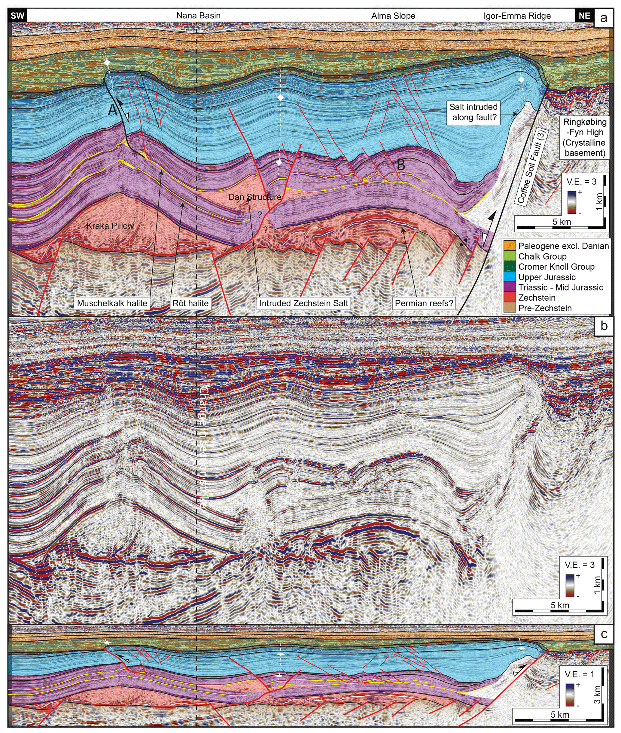
Figure 7(a) Interpreted seismic section across the Kraka structure and Igor–Emma Ridge. Thick-skinned inversion of the Coffee Soil Fault was possibly enhanced by Zechstein salt along the fault surface. Thin-skinned inverted faults sole out into a detachment in the Muschelkalk halite on the NE flank of the Kraka Pillow carapace (marked as “A”). In the Dan Structure, Zechstein salt has intruded along the Triassic evaporite layers. Late Cretaceous folding above it is evident. Named structures in the header and marked fold axes indicate Late Cretaceous topographical elements unless otherwise noted. See the text for further details. (b) Uninterpreted section. (c) Interpreted section with no vertical exaggeration. An overview of the stratigraphic units and mapped surfaces is found in Fig. 3. The location of the section is indicated in Figs. 1, 5c, 12a, and 11c. Seismic data are supplied by DUC.
A large number of subsidiary normal faults offset the Top pre-Zechstein with a significantly higher density in the western part of the study area (Heno Plateau) compared to east of the Gorm–Tyra Fault (Figs. 1, 6, 7). Although they are often difficult to map with certainty due to limited data quality at depth, their strike trends are generally between E–W and N–S, i.e. equivalent to those of the Coffee Soil Fault segments and the Gorm–Tyra Fault. We have observed no reverse faults at Top pre-Zechstein level.
Lower Permian Rotliegend units underlie the Top pre-Zechstein in the western part of the study area, where Zechstein units are absent (Figs. 4a, 5c). No wells penetrate beyond the Triassic in the deeper parts of the DCG in the study area, meaning that the nature of the pre-Zechstein basement is unknown here. Parallel reflections on both sides of the Gorm–Tyra Fault suggest that Paleozoic deposits may extend across much of the study area below the Zechstein salt (marked “A” in Fig. 6a)
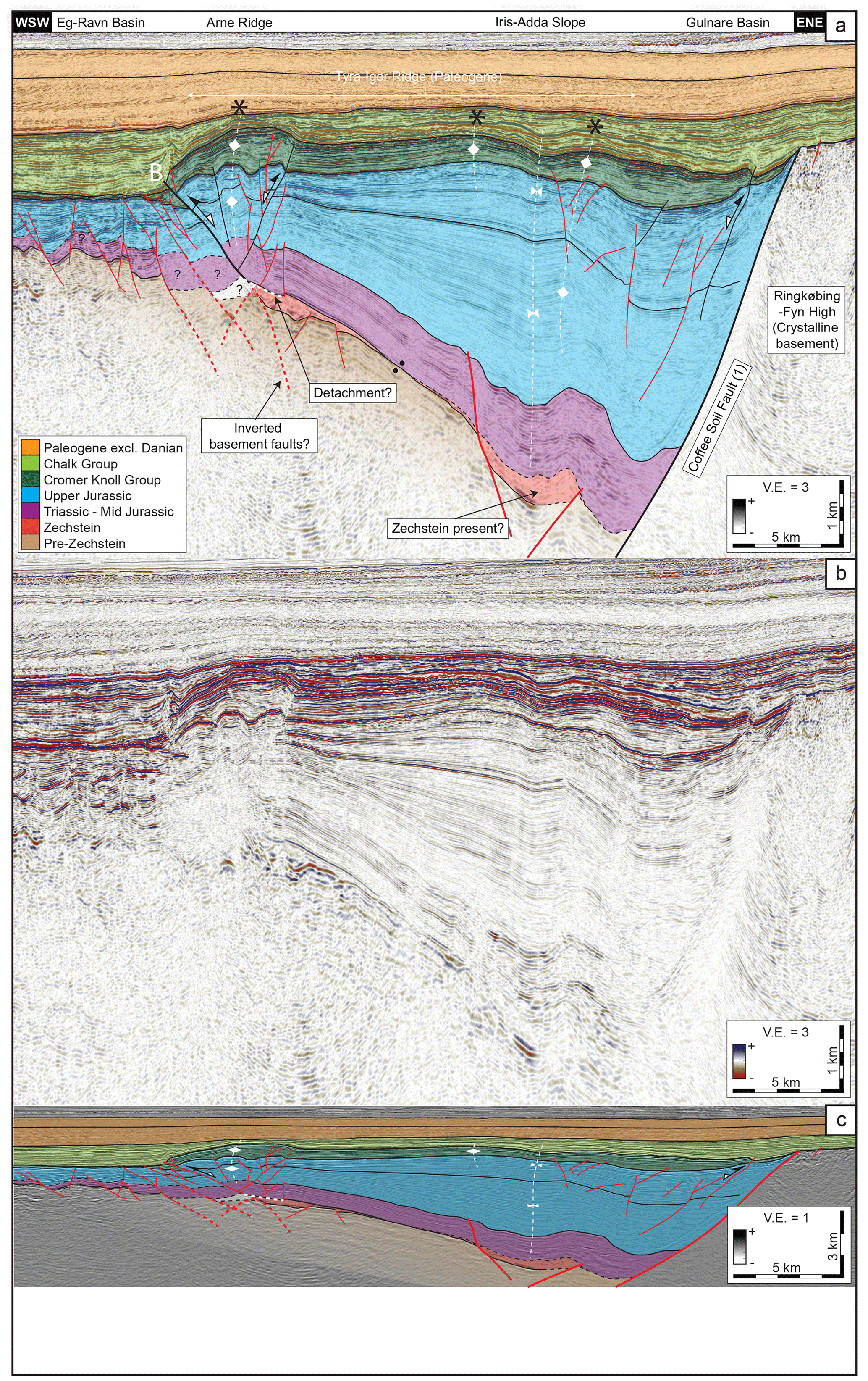
Figure 8(a) Interpreted seismic section across the Arne Ridge and Coffee Soil Fault (segment 1). The Tyra–Igor Ridge (Paleogene inversion) covering several of the Mesozoic structures is also indicated. The prominent Arne Ridge formed with the inversion of the Arne–Elin Graben above the western limit of the Zechstein units. An inverted fault at the western limit of the Arne Ridge detaching in the Zechstein salt is marked “B”. Observed anticlines are indicated with “∗” and a trace line. Note the lack of buttressed folds in the immediate hanging wall of the Coffee Soil Fault. Named structures in the header and marked fold axes indicate Late Cretaceous topographical elements unless otherwise noted. See the text for further details. (b) Uninterpreted section. (c) Interpreted section with no vertical exaggeration. An overview of the stratigraphic units and mapped surfaces is found in Fig. 3. The location of the section is indicated in Figs. 1, 5c, 12a, and 11c. Seismic data supplied by DUC.
4.2 Current distribution and geometry of Zechstein units
Zechstein units range in thickness from thin (< 50 m) or below seismic resolution in the central part of the study area, to extreme local maxima (> 3000 m) in diapiric structures in the southern (Salt Dome Province) and very northwestern parts (Figs. 5e–f, 9). Zechstein deposits are absent where the Top pre-Zechstein is the shallowest i.e. on the Heno Plateau to the west (cf. Vigeland Ridge of Gowers and Sæbøe, 1985) and on the Ringkøbing–Fyn High. Only a few significant faults offset the Top Zechstein surface within the larger basin (Figs. 5d, 6). Along the western pinch-out of Zechstein deposits on the half-graben dip-slopes, we have interpreted three reverse faults or thrusts that sole out into Zechstein units (Figs. 6, 8, 10). The two largest occur along the Arne Ridge and Bo–Jens Ridge, where they reach Cretaceous levels (Fig. 12b and marked “B” in Figs. 6, 8, 10). The third occurs in relation to folded overburden strata at the Edna structure (marked “C” in Fig. 6). Also detaching into the Zechstein, a prominent normal-fault trend links the Gorm, Skjold, and Dan structures (marked “A” in Fig. 5d). The northern part of the Gorm–Tyra Fault offsets the thin package of Zechstein found here (Fig. 6), while to the south (Fig. 9), an initial thicker Zechstein deposit “drapes” the Gorm–Tyra Fault, forming pillows at the footwall crest and up-dip in the hanging wall. Therefore, the Gorm–Tyra Fault is only expressed as a large monocline at shallower levels (Fig. 9).
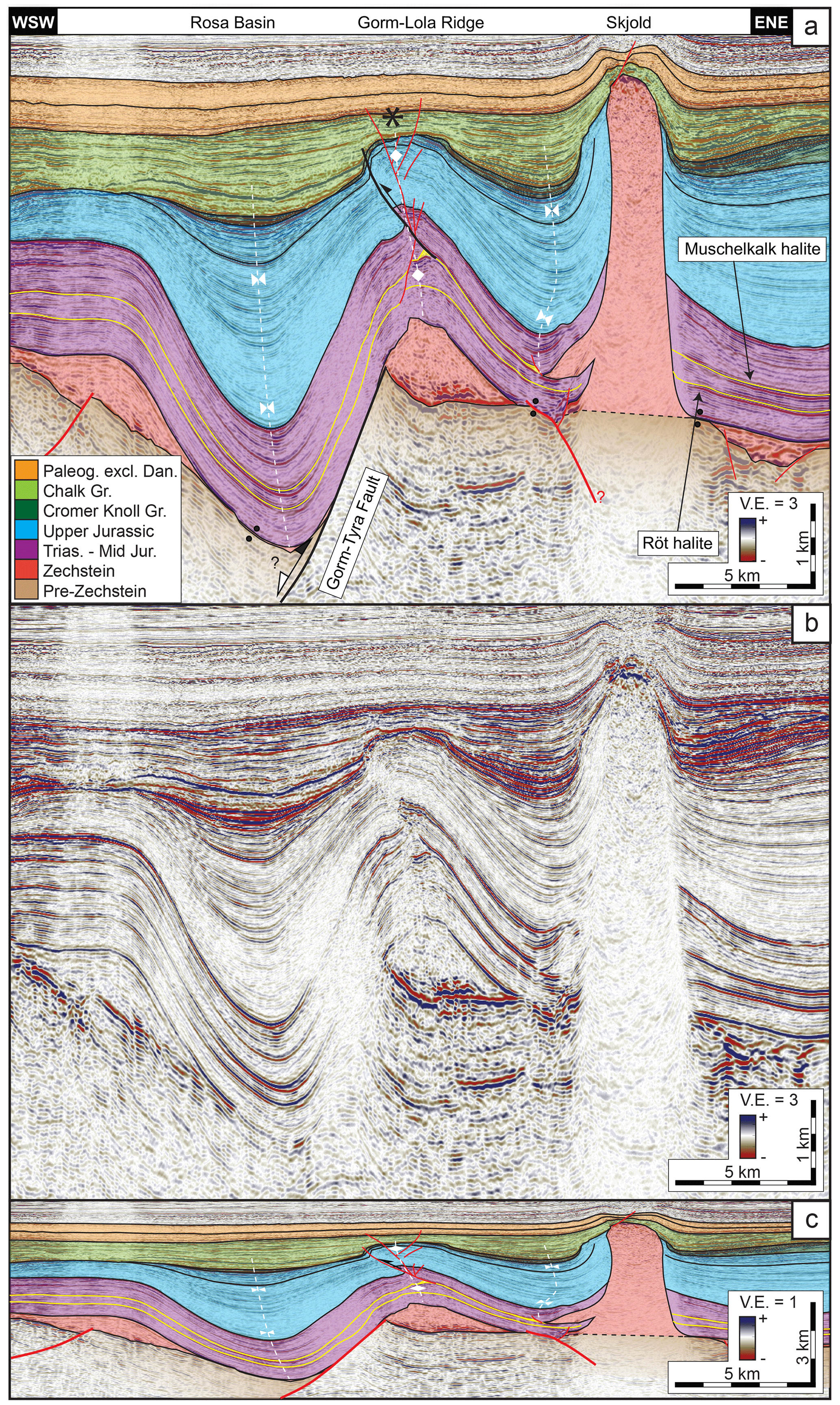
Figure 9(a) Interpreted seismic section across the Gorm–Lola Ridge and Skjold structure. Note the salt weld along the Gorm–Tyra fault surface and the position of the Gorm–Lola ridge above the Lola Salt structure. A thin-skinned reverse fault sole out into a detachment along a Triassic evaporite layer in the flank of the structure. Observed anticlines are indicated with “∗” and a trace line. Named structures in the header and marked fold axes indicate Late Cretaceous topographical elements unless otherwise noted. See the text for further details. (b) Uninterpreted section. (c) Interpreted section with no vertical exaggeration. An overview of the stratigraphic units and mapped surfaces is found in Fig. 3. The location of the section is indicated in Figs. 1, 5c, 12a, and 11c. Seismic data are supplied by DUC.
The constructed mobile-salt pinch-out effectively marks the boundary of the Salt Dome Province in the south, while only a small area in the north contains potentially mobile Zechstein (Fig. 5f). In the Poul Basin area, only pockets of Zechstein reaching thicknesses > 200 m occur (Fig. 5e). These pockets fill topographical lows in the Top pre-Zechstein surface that seem to have formed from erosion rather than faulting (Duffy et al., 2013). The Salt Dome Province and the northern Tail End Graben area are characterized by large salt pillows, ridges, and rollers with extreme thicknesses of Zechstein (> 400 m; Fig. 5f). In the Salt Dome Province, the areas of thin or absent Zechstein between these structures show typical signs of salt deflation and evacuation, which led to the formation of minibasins, e.g. in the hanging wall of the Gorm–Tyra Fault (Figs. 6 and 9) and west of Kraka (Fig. 7). The Triassic–Jurassic cover is folded into synclinal minibasins that trend parallel to the salt structures and show thickening in their centres. Late Jurassic units show significant onlap onto the margins of the synclinal mini-basin centres. However, onlaps also occur in older units (e.g. Fig. 9). We therefore infer that Zechstein salt was initially deposited relatively evenly across the Salt Dome Province (in agreement with Duffy et al., 2013), including the area west of the Gorm–Tyra Fault. The Zechstein salt was subsequently mobilized due to rifting and eventually evacuated from below subsiding minibasins and into growing salt structures and diapirs. This process left behind the overburden welded (sensu Wagner and Jackson, 2011) to the pre-Zechstein units (see also Rank-Friend and Elders, 2004; Duffy et al., 2013).
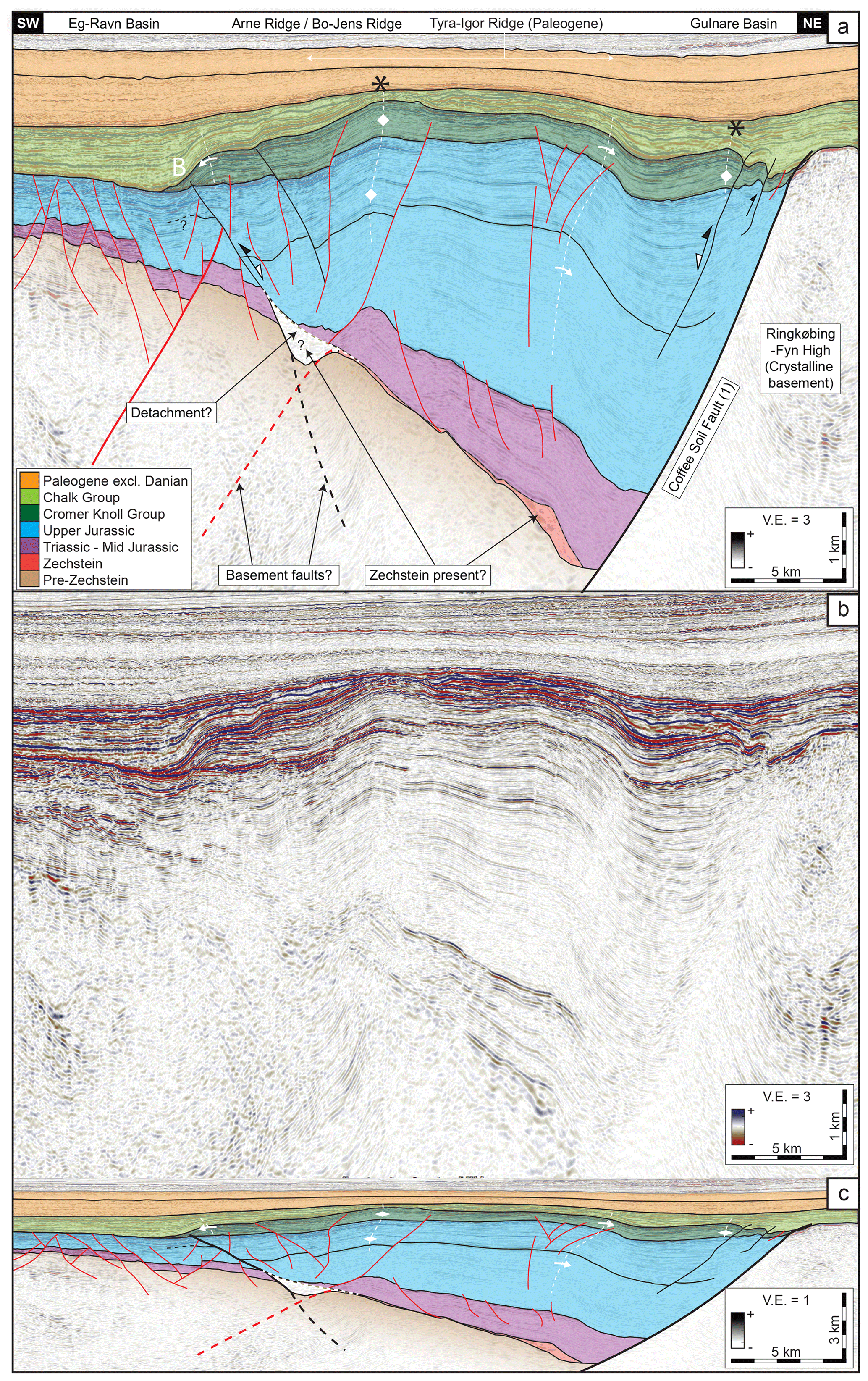
Figure 10(a) Interpreted seismic section across the confluence of the Arne and Bo–Jens ridges and the Coffee Soil Fault (segment 1). Zechstein units may be absent in this area, although they are indicated. Note the high degree of folding in the sedimentary cover relative to reverse throw on inverted faults. Named structures in the header and marked fold axes indicate Late Cretaceous topographical elements unless otherwise noted. (b) Uninterpreted section. (c) Interpreted section with no vertical exaggeration. An overview of the stratigraphic units and mapped surfaces is found in Fig. 3. The location of the section is indicated in Figs. 1, 5c, 12a, and 11c. Seismic data are supplied by DUC.
Several prominent salt structures of varying maturities populate the current-day mobile-salt domains (Figs. 5f, 6, 8, 9). Salt stocks of different sizes populate the Salt Dome Province, including the Edna, Rolf, Dagmar, John, and Skjold structures. These all penetrate Cretaceous strata (Fig. 11c) with the John structure reaching the shallowest level around 0.6 km below sea level in the borehole John-1 (Fig. 1; Chevron Petroleum Company of Denmark, 1983). Other intrusive diapirs (sensu Jackson and Talbot, 1986) include the Gorm, South Arne, and Dan structures. At a glance, their 3D shapes are elliptical in map view and parallel to the underlying faults (Fig. 5f). Although their influence is evident at base Cretaceous levels (Fig. 11e), they have not penetrated into Cretaceous strata. The Dan structure is remarkable, as Zechstein salt has delaminated the Triassic succession laterally along weak Triassic evaporite layers to form wings or salt wedges (sensu Kockel, 2003) that extend laterally for several kilometres (Rank-Friend and Elders, 2004; Fig. 7). A handful of concordant (sensu Jackson and Talbot, 1986; e.g. pillows, anticlines, and rollers) salt structures with more than 1000 vertical metres of salt are present in the modern-day mobile-salt domains (Fig. 5f). One of them may be considered part of the Dagmar structure, whereas the four others are isolated structures. These include the named structures Kraka (ca. 1800 vertical metres of salt) and Lola, as well as a previously unnamed structure near the Jens-1 well, which we refer to as the Jens Pillow. A network of smaller salt rollers connect the larger structures in the southern part of the study area (Fig. 5f). The elongated axes of all salt structures appear to align with the underlying basement fault trends (Fig. 5f). This is especially evident to the east of the Gorm–Tyra fault. In the northeastern part of the Tail End Graben, a local Zechstein thickness maximum may represent a significant volume of non-mobilized salt considering its depth, although the data are noisy in this area (Fig. 5). Korstgård et al. (1993) interpreted such remnant Zechstein units to be present in the immediate hanging wall of the Coffee Soil Fault just north of our study area, which lends supports to this interpretation.

Figure 11Depth and structure maps constructed from seismic data illustrating the deformational geometries of the base and top of the Chalk Group (Late Cretaceous, syn-inversion). (a) Base Chalk Group depth and (b) structures. A high number of smaller normal faults offset this surface (b). These were induced mostly from compaction or crestal collapse above or across inversion structures, i.e. local extension. (c) Top Chalk Group depth and (d) structures. Note the expression of the Tyra–Igor Ridge, which formed due Paleogene basin inversion. Crestal faults are evident above some prominent inversion ridges. (e) Chalk Group isochore (thickness) map and (d) structural elements. This illustrates the marked change in subsidence patterns compared to the pre-inversion basin (Fig. 12c and d). In this case, depocentres are located outside the zone affected by significant inversion, while thinning occurs above areas of relative uplift. In panels (c) and (e), A marks the post-Chalk Group and syn-Chalk Group effect of an active Arne Structure. See the text for more information. Names in brackets indicate pre-existing structural elements; ∗ indicates names from Jakobsen (2014). An overview of the stratigraphic units and mapped surfaces is found in Fig. 3. The colour scale used (Batlow) was constructed by Crameri (2018).
Beyond the mobile-salt pinch-out, we infer the presence of mechanically weak Zechstein units from the observation that the Top Zechstein reflection (base of the Triassic carapace) is smooth and continuous, while the Top pre-Zechstein is more uneven and discontinuous. In parts of the Tail End Graben, this contrast in morphology is not apparent (marked “A” on Fig. 5c). Zechstein units may be absent here or only present in thicknesses near the limit of seismic resolution. Due to low data quality at depth in this area, the exact position of the western pinch-out of the Zechstein units and their thicknesses are unclear along the southern Arne–Elin trend (Figs. 1, 5f).
4.3 Structural styles of Late Cretaceous inversion
Our following descriptions of Late Cretaceous inversion structures agree overall with those of Vejbæk and Andersen (1987, 2002) and Cartwright (1989). Unlike these works, we do not take into account the diachronous and gradual development of many of the structures. Instead, we address the structural connections between the upper inversion structures and the Zechstein units and pre-Zechstein basement below.
Across our study area, Late Cretaceous inversion is evident from the geometry of the open growth folds and their relations to reverse faults along the outer margins of the uplifted basins (Figs. 6–10). Relative uplift is evident especially from Lower Cretaceous units (Cromer Knoll Group) that sit at shallower levels compared to adjacent areas with no preserved Lower Cretaceous units (Figs. 6, 7, 9, 10). The distribution of major growth folds, characterized by onlapping Chalk Group strata, is evident from the isochore map of the syn-inversion Chalk Group (Fig. 11e–f). Thinning of Chalk Group units and truncations are also evident on the fold crests (marked with ∗ in Figs. 6, 8, 9, 10). Major folds generated by inversion are mostly recognizable as monoclines and asymmetric anticlines with steeper forelimbs facing the marginal troughs and more gently sloping backlimbs (Figs. 6, 8, 9, 10c, e.g. Koopman et al., 1987; Badley et al., 1989). In the most extreme cases (e.g. Bo–Jens Ridge, Fig. 6), inversion ridges express a relief of ca. 1000 m relative to the adjacent marginal basins at Base Chalk Group level.
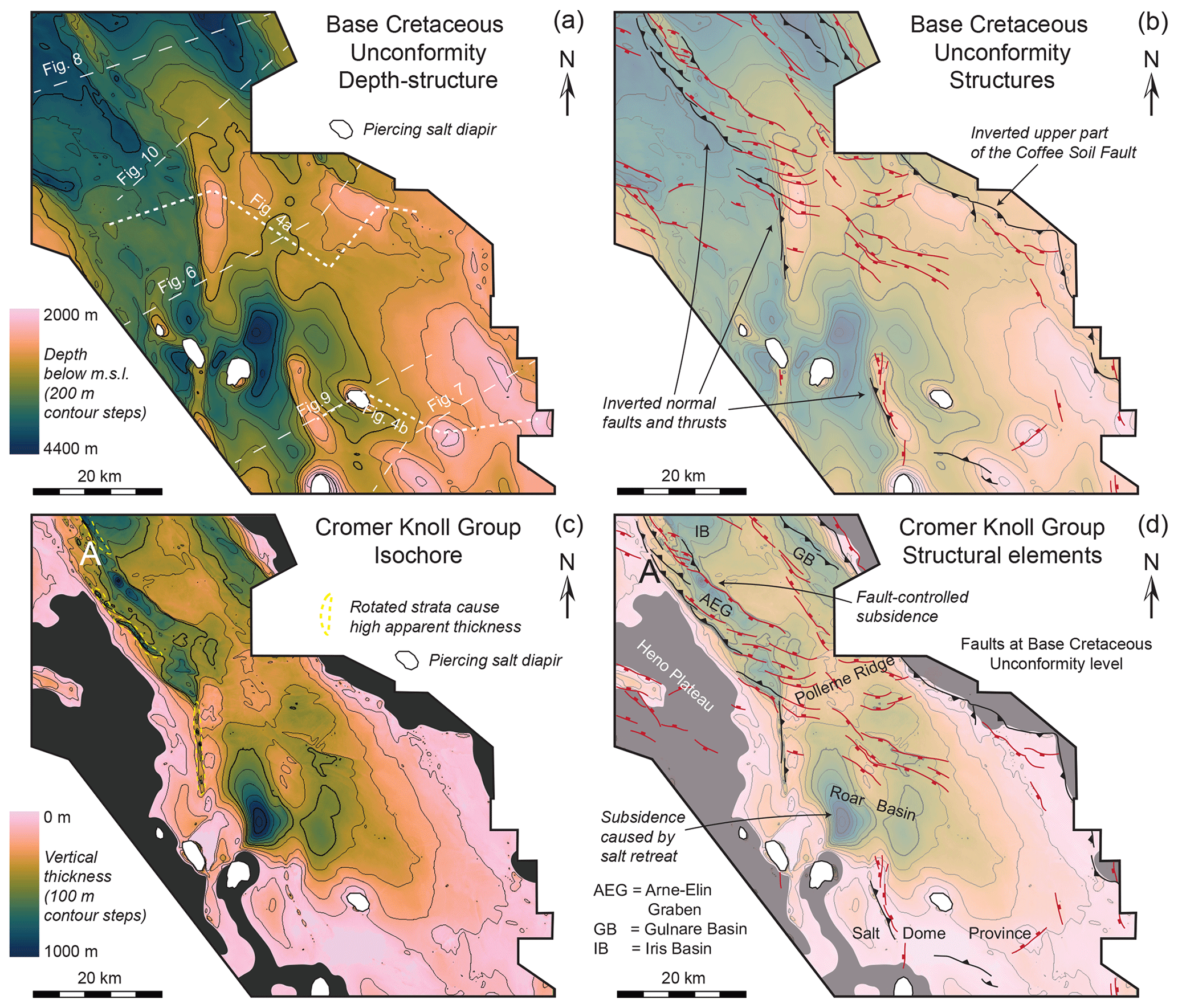
Figure 12Depth and structure maps constructed from seismic data illustrating the deformational geometries and extent of the Cromer Knoll Group (Lower Cretaceous, post-rift and pre-inversion). (a) Base Cretaceous Unconformity depth and (b) structures. The fault map illustrates the selective inversion of inherited normal faults during Late Cretaceous shortening, which caused the abundance of reverse faults and thrusts at this level. (c) Cromer Knoll Group isochore (thickness) map and (d) structural elements. These illustrate the pre-inversion position of depocentres in the study area. Thickness changes can be linked to migration of mobile Zechstein salt towards the northwest (marked as “A”) and south, respectively. See the text for further information. An overview of the stratigraphic units and mapped surfaces is found in Fig. 3. The colour scale used (Batlow) was constructed by Crameri (2018).
The faults related to inversion are mostly inverted extensional faults that grew slightly upwards during shortening, giving them the typical expression with reverse offsets only in their highest parts (e.g. Figs. 6, 8, 10). Relative to folding, reverse faulting is significantly less prominent at Base Chalk Group level and in the syn-inversion strata above (Fig. 11b), as seen from e.g. the Bo–Jens Ridge and the Adda Ridge (Fig. 6). Much of the shallow reverse faulting only reached into the pre-inversion Lower Cretaceous units, while fault propagation folding probably accounted for the strain at seafloor level. Faults offsetting the base Cretaceous unconformity (Fig. 12b) reveal that reverse reactivation of normal faults was selective, as not all faults with similar strike directions inverted, as can be observed by comparing Figs. 5f, 6, and 12b, where, e.g. the Gorm–Tyra Fault does not invert in contrast to the Coffee Soil Fault. All inversion folds and faults show strike directions within WNW–ESE to N–S, which concurs with the structural trends of the sub-salt basement. From our observations, we outlined the margins of the inverted areas (indicated on Fig. 11f) outside of which no significant signs of Late Cretaceous inversion are apparent. The zone within the margins spans the entire southern study area and becomes narrower towards the north.
A number of smaller extensional growth faults occur locally in the Chalk Group, which formed and were active in Late Cretaceous times, possibly during inversion. Some likely formed due to differential compaction across large but inactive extensional faults (Fig. 11b). Others populate the crests of inversion ridges (e.g. Bo–Jens Ridge, Fig. 6, and Gorm–Lola Ridge, Fig. 9) or appear near the inversion margins (Fig. 11b and d). Local extension, e.g. due to outer-arc stretching or slope instabilities, could have generated these faults (see, e.g. Back et al., 2011).
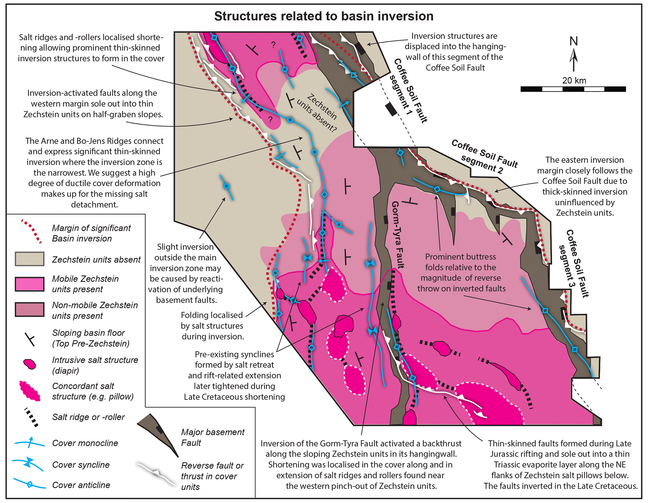
Figure 13Overview of active structures during Late Cretaceous basin inversion in the study area. This illustrates the spatial relationships between the main sub-salt basement structures, Zechstein units and salt structures, and inversion structures in the cover units. Note the concentration of thin-skinned inversion structures along the western pinch-out of the Zechstein units and directly above the adjacent salt ridges and rollers. Note the different expressions of inversion or lack thereof directly above the major basement fault tips. Reverse reactivation of the Coffee Soil Fault segment 1 and the Gorm–Tyra Fault is inferred in order to balance the thin-skinned shortening expressed along the western margin of the inversion zone. See the text for further explanation.
Post-Danian inversion is evident from the wide and gentle Tyra–Igor Ridge (Fig. 6), which is expressed in the Top Chalk Group topography (Fig. 11d; see also Vejbæk and Andersen, 1987, 2002). Compared to the structural styles of Late Cretaceous inversion, this is markedly different. Instead of prominent folds along the margins of the uplifted areas, a broad and low-amplitude anticline, which is centred above the Late Jurassic rift depocentres, characterizes this inversion. In addition, no associated reactivation of extensional faults in the cover units is evident.
4.3.1 Eastern inversion margin
The eastern margin of the inverted zones follow the upper trace of the Coffee Soil Fault, although slightly more basinward along segment 1 (Fig. 11f). Striking parallel to segments 2 and 3, the prominent Adda (D in Fig. 6) and Igor–Emma ridges display buttressed folds situated directly above inverted rift-bounding faults (Figs. 6, 7 and 11f). This structural configuration is observable in a wealth of similar settings (Williams et al., 1989). The axial traces of these folds are traceable ca. 1–2 km into the deeper pre-inversion units. Below this, the Jurassic and Triassic units show no apparent reverse drag along the surface of the Coffee Soil Fault. Noticeably, a possible Zechstein salt structure is located along the plane of the Coffee Soil Fault below the southern part of the Igor–Emma Ridge (Fig. 7). The top of this structure coincides with the base of the anticline axial trace, indicating a genetic relationship with the inversion structure above. Local salt movements may have enhanced or even controlled the geometry of the inversion anticline. The basin units above the Poul Plateau are not significantly uplifted and show no buttress folds at Cretaceous levels, although reverse offsets in the upper part of the Coffee Soil Fault segments are evident. To the southwest, the extensive Alma Slope is seemingly unaffected by distinct folds or reverse faults.
Only a narrow but prominent anticline overlies the southernmost part of segment 1 of the Coffee Soil Fault northwest of Adda Ridge. Unfortunately, this structure is obscured by the gap in the seismic data here (Fig. 11f). Following the Coffee Soil Fault northwest, no significant inversion structures occur directly above it. Instead, the northeast-dipping Iris–Adda Slope (Fig. 11) provides a more gradual transition from non-inverted footwall to inverted basin. Syn-inversion faults and folds populate this area; most noticeably, a large monocline is traceable several kilometres downwards into the Tail End Graben fill (Fig. 10).
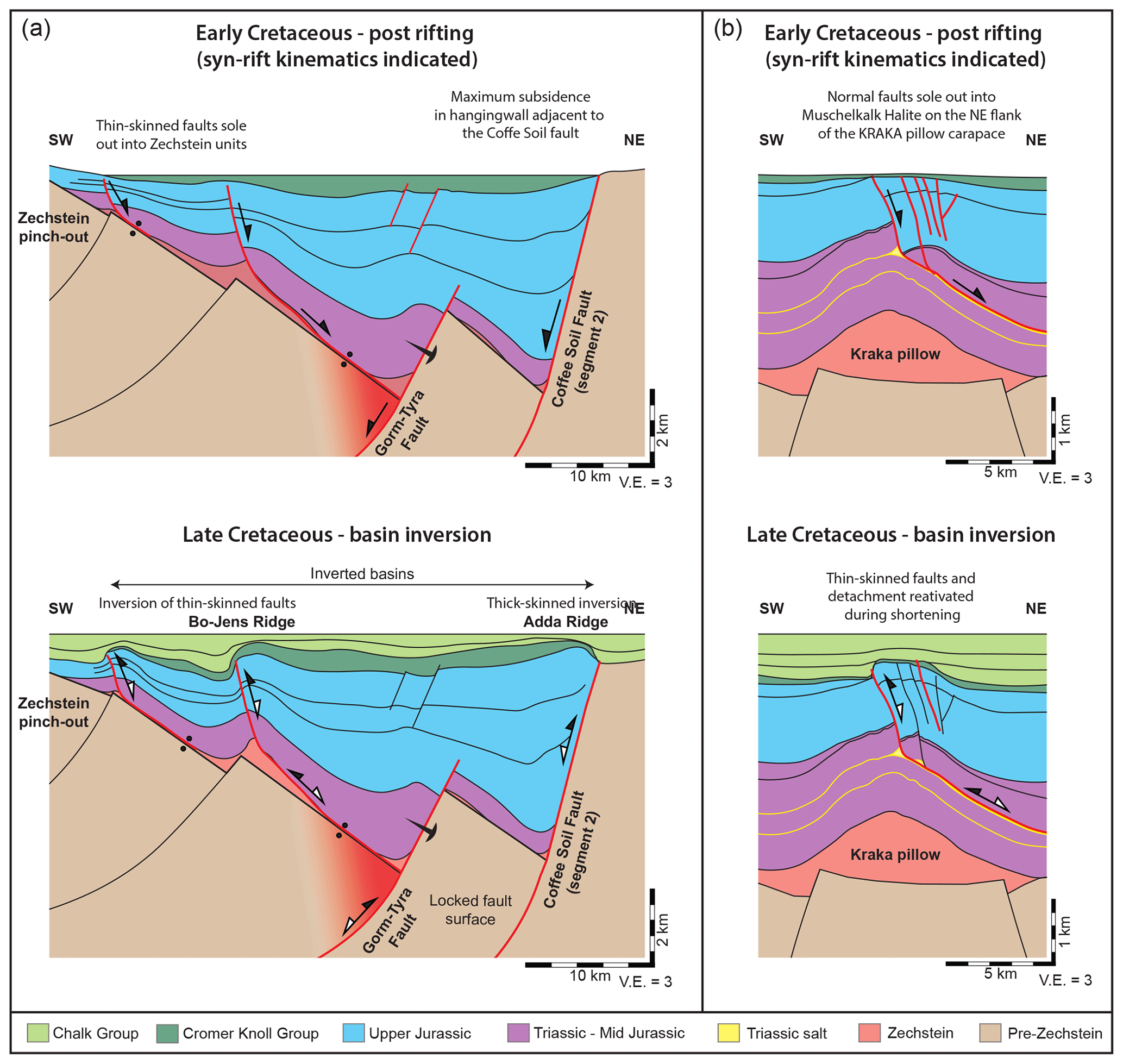
Figure 14Simplified 2D sections illustrating the development of various structural styles of basin inversion from the pre-inversion rift basins in our study area. Active faults are indicated in red. Note the different scales for the two sections. (a) Section constructed from the interpretation seen in Fig. 6 (See Fig. 1 for location). The western margin of inversion is characterized by thin-skinned inversion with Zechstein units acting as detachment. Thin-skinned structures initially developed during rifting at the pinch-out of the Zechstein units and above salt ridges. Thick-skinned inversion of the Coffee Soil Fault formed along the eastern margin, e.g. the Adda Ridge. Inversion of the deeper Gorm–Tyra fault caused a triangle zone (indicated by red area) to develop with a thrust detachment through the thin Zechstein units along the basin floor. The upper part of the Gorm–Tyra Fault did not reactivate and hence no inversion structures formed directly above it. Instead, shortening was accommodated in the cover units by inversion of the thin-skinned faults soling out into Zechstein units. This mechanism is also inferred for segment 1 of the Coffee Soil Fault and the development of Arne Ridge (Fig. 8). (b) Section constructed from the interpretation seen in Fig. 7 (See Fig. 1 for location), illustrating the Kraka structure before and after Late Cretaceous inversion. Note the detachment in a Triassic salt unit (Muschelkalk halite).
4.3.2 Western inversion margin
Going north to south, the western margin of the inverted areas separates the Eg–Ravn Basin from the Arne Ridge and Bo–Jens Ridge (Figs. 1c, 6, 8, 10), after which it follows a group of smaller ridges connecting the Edna and Rolf salt structures (Figs. 1c, 5d, 6). The Arne Ridge formed due to inversion of the Arne–Elin Graben (Fig. 1a), which was a fault-bounded depocentre in Early Cretaceous times (Vejbæk and Andersen, 1987; see Fig. 12c–d). The Arne Ridge represents the most pronounced inversion structure in the northern part of our study area (Fig. 8). In the northwest, it connects to the South Arne salt structure, and in the southeast it connects to the Bo–Jens Ridge. Although it seems to follow a fault trend in the Top pre-Zechstein surface, these faults are poorly visualized in the seismic data and their dip directions are uncertain. The extent of the Zechstein salt below the Arne Ridge is also uncertain towards the southeast. It may extend along most of the structure as a small salt body into which the southwest-verging thrusts and reverse faults sole out (Figs. 8, 10).
The Bo–Jens Ridge strikes north to south and expresses significantly less faulting relative to the Arne Ridge (Fig. 6). This coincides with the thin Lower Cretaceous units in the structure (Fig. 12c–d), indicating that this was not a pre-inversion depocentre. The anticlinal fold is larger to the north and plunges towards the south, where it is more monoclinal and eventually undistinguishable from folding related to the Jens Pillow. It follows a west-dipping normal fault in the basement, which is either absent or obscured below the northern part. The associated reverse fault in the cover below the fold soles out into Zechstein units along the crest of a salt roller. This roller forms the northernmost point of the southern mobile-salt domain. Notably, the reverse fault here records the deepest net reverse offset on a fault in the study area along the Near Top Callovian surface. Judging from the thickening towards the east of the Upper Jurassic units, the fault probably formed during rifting before it was inverted in the Late Cretaceous. Slight folding of the cover units in the adjacent part of the Eg–Ravn Basin reveals the effect of inversion in front of Bo–Jens Ridge.
A group of narrow anticlinal folds cored by mobile Zechstein units emerge from the southern Eg–Ravn basin (Fig. 11e–f). These record shortening and relative uplift on their east-facing flanks, while only a single small break-thrust emerges from the detachment (marked by “C” in Fig. 6). The folds connect the Edna and Rolf salt structures before continuing southwards out of the study area.
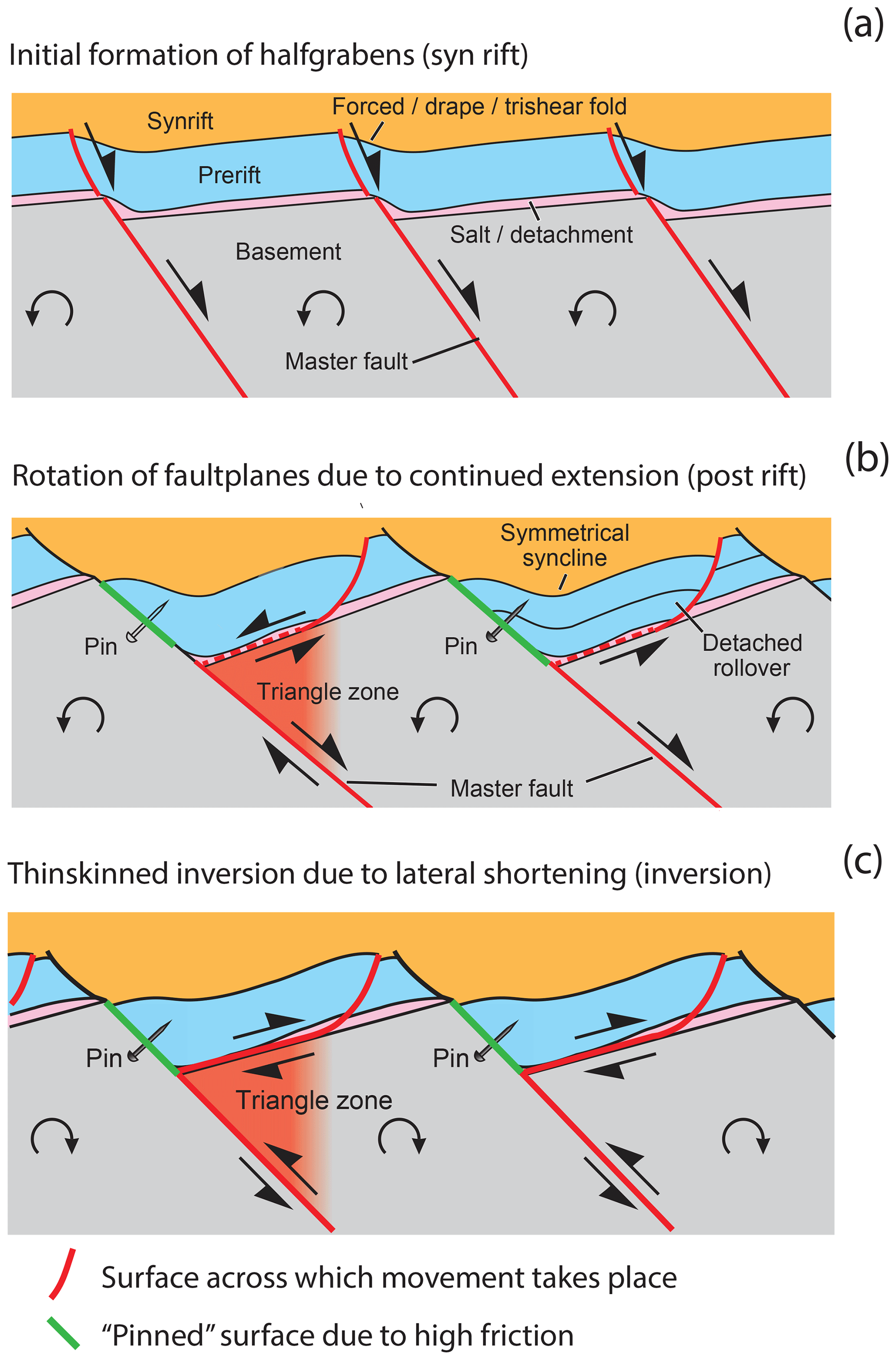
Figure 15This schematic diagram modified from Stewart (2014) shows both thick-and thin-skinned extension and inversion in an area with a relatively thin salt layer. Panel (a) shows the initial domino block rotation and decoupled basement and cover faults. Salt is accumulated on the hanging wall at the fault plane. Panel (b) shows the geometry at increased extension where the basement fault planes are rotated to a shallower dip and salt is no longer present at the fault plane. The sediment–basement contact is interpreted to have a high friction (pinned and marked in green) which facilitates the formation of thin-skinned faults taking up the extension (along the red fault). Panel (c) shows the movements during inversion. The shortening is taken up by the same fault planes, along which there was movement during the late extension, (b) whereas the high-friction pinned segment remains fixed.
4.3.3 Salt Dome Province
The wide zone between the inverted margins in the southern part of our study area is dominated by large salt structures as described above (Fig. 5f). There are few structures that unequivocally indicate shortening in the cover units, and there are none below the salt (Figs. 7, 9). Two thin Triassic evaporite units act as secondary detachment horizons for Mesozoic faults above the Zechstein (Fig. 7): the Muschelkalk Fm. halite and the Röt Fm. halite, which Michelsen and Clausen (2002) documented from U-1 well logs. According to them, the Main Röt halite member is ca. 50 m and the Muschelkalk halite member ca. 50 m thick in the U-1 well (for location see Fig. 1).
Above the footwall of the Gorm–Tyra Fault, the Gorm–Lola Ridge is a prominent and complex structure connecting the Gorm diapir and the Lola pillow (Figs. 5f, 9). Stratal thinning indicates that it formed in the Late Jurassic and remained a topographical high well into the Late Cretaceous. Onlaps in the Upper Cretaceous and a reverse fault soling out into the Muschelkalk halite, indicate uplift and shortening related to inversion. WSW–ESE-striking faults sole out into the Muschelkalk halite above the Kraka pillow as well (marked A in Fig. 7a). Only the southernmost of these faults records both Late Jurassic extension and later inversion as seen from the reverse offset in its upper part. Although not apparent from Cretaceous levels, this reverse fault offset at the base of the Upper Jurassic can be traced westwards to where the fault connects to the reverse fault below the Gorm–Lola Ridge. Late Cretaceous folding above the Dan structure (Fig. 7) may be a result of shortening or halokinesis. Nearby along the same seismic section, a group of extensional faults sole out into the deeper Röt halite (marked B in Fig. 7a). These faults are of Early Jurassic age and indicate no reactivation during inversion.
4.4 Mobile-salt distribution and movements during the Cretaceous
The thickness of the Lower Cretaceous units in the study area is small compared to that of Upper Jurassic units (Figs. 7–10). Locally pronounced thickness maxima indicate areas of increased Early Cretaceous subsidence, namely in the Arne–Elin Graben, Iris, Gulnare, and Roar basins (Fig. 12d). Of these, only the Gulnare Basin and the Arne–Elin Graben show fault-controlled subsidence as indicated by the thickness changes across adjacent faults. Along segments 2 and 3 of the Coffee Soil Fault, the Lower Cretaceous thins and onlaps towards the fault trace, suggesting no syn-depositional activity of the fault (marked as “D” in Fig. 6). In the Salt Dome Province adjacent to segments 2 and 3 of the Coffee Soil Fault (CSF), we lack a basal sub-salt slope dipping towards the master fault (Coffee Soil Fault) along with a weakened (thin and faulted) cover above the upper part of this slope. This configuration of weak zones seems to have provided ideal conditions for the thin-skinned inversion ridges along the western inversion margin. This is because the detachment and inverted cover faults, both antithetical to the relevant major basement fault (CSF 1 or the Gorm–Tyra Fault), approximate a plane dipping ca. 20–30∘, which is ideal for reverse slip. Vejbæk (1986) showed that the depocentre of the Roar Basin shows characteristic onlaps onto the flanks of a large syncline in the units below, which, along with a lack of remaining Zechstein units below the Roar Basin (marked as “A” in Fig. 5e), indicates that it formed as salt moved towards the neighbouring salt structures (see Vejbæk, 1986). The Gulnare and Iris basins may also have seen increased subsidence due to on-going salt movements towards the west and northwest after Late Jurassic rifting ceased (see also Korstgård et al., 1993).
Significant Early Cretaceous faulting occurred in the Arne–Elin Graben, focusing subsidence along its northeastern flank, which is defined by a southwest-dipping fault (Fig. 12d). Thinned units towards the northwest (marked “A” in Fig. 12c) indicate that the South Arne structure (Fig. 1a) may have been growing at this point. As mentioned, remnants of a salt ridge may extend southeast below the Arne–Elin Graben. Salt movements from this ridge towards the South Arne structure could have focused and enhanced the tectonically induced subsidence of the narrow graben, which commenced in the Late Jurassic (Møller and Rasmussen, 2003).
Continued halokinesis in the Late Cretaceous is evident from the Chalk Group isochore map (Fig. 11e–f). Here, the South Arne structure is even more pronounced as indicated by thickness variations (marked as ”A” in Figs. 11e, 12c), suggesting that it accentuated contemporaneously with the inversion of the Arne–Elin Graben. Distinct synclinal minibasins occur parallel to inversion anticlines and monoclines above the Tail End Graben and in the southern study area (Figs. 6, 8, 9), indicating that the lower part of the Chalk Group was folded and subsequently onlapped by younger units. The synclines widen with depth in the units below until they reach the basin floor. We interpret these structures as the results of combined salt movement and buckling due to inversion. Comparing the isochore maps of the Cromer Knoll Group (Fig. 12c) and the Chalk Group (Fig. 11e) shows a southward migration of the depocentre in the Early Cretaceous Roar Basin (marked as ”A” in Figs. 11e, 12c). This may indicate the progressive welding of the Triassic units to the basin floor as mobile salt migrated south along the Gorm–Tyra Fault. Additionally, Late Cretaceous synclinal minibasins formed adjacent to the Dagmar and Skjold structures (see Fig. 5f for salt structure locations) due to salt evacuation into these structures (Fig. 11e–f). As indicated by post-Danian subsidence around them (marked as ”A” in Fig. 11c), the South Arne and Edna structures continued their growth into Cenozoic times. Thickening around the Dagmar and (to some degree) John structures point towards continued growth as well (Fig. 11).
In this chapter, we will as announced earlier compile and discuss our results and interpretations in relation to the following points.
-
The controls of evaporites on inversion structures in the study area and mildly inverted basins in general.
-
The kinematics of basement shortening and basement fault inversion.
-
The magnitude and direction of shortening during inversion.
-
The mechanisms responsible for ductile deformation styles in the cover units.
Our most important observations and interpretations for the following discussion are as follows.
-
All basement faults record net normal offsets at Top pre-Zechstein level (Fig. 5b), and we have not interpreted compressional structures below the salt with certainty.
-
Zechstein units extend across most of the deeper basin floor in the hanging wall of the Coffee Soil Fault and the Gorm–Tyra Fault (Fig. 5c). Zechstein units pinch out on the western half-graben dip-slopes and along the Coffee Soil Fault. Mobile-salt structures are restricted to the Salt Dome Province and the northern mobile-salt domain, although salt ridges extend towards the centre of the study area below the Bo–Jens Ridge and possibly the Arne Ridge (Fig. 5d).
-
Prominent folding and selective fault reactivation, which characterize Late Cretaceous basin inversion, affected the deeper syn-rift units in several places (e.g. Fig. 10). Along the western margin of the inverted zones, the dominating structure is thin-skinned inversion structures with reverse faults soling out into Zechstein units (Fig. 11f). The major inversion folds not only follow basement fault trends but also overlie salt ridges (Fig. 13). Along the eastern margin, thick-skinned inversion ridges follow the upper trace of the Coffee Soil Fault, except along segment 1 where the inverted basin rises only gradually into the hanging wall (Fig. 8). In the Salt Dome Province, a few smaller inverted faults sole out into the thin Triassic Muschelkalk halite below the Gorm–Lola Ridge (Fig. 9) and above the Kraka salt pillow (Fig. 7).
-
During the Early Cretaceous, salt evacuation formed the Roar Basin depocentre and possibly contributed to the development of the Arne–Elin Graben, the Iris Basin, and the Gulnare Basin in combination with extensional tectonism (Fig. 12c–d). Salt flow into or away from an area may have enhanced, respectively, anticlinal or synclinal folding in the cover above. These interpretations imply that mobile Zechstein salt was initially present in significant amounts beyond the modern-day mobile-salt pinch-out in the area.
5.1 Evaporite controls on inversion structures
In addition to the correlation between the major Late Jurassic rift depocentres and the Late Cretaceous inversion zones (Vejbæk and Andersen, 1987, 2002; Cartwright, 1989), our results show a strong correlation between the extent of the Zechstein units and salt structures and the areas affected by Late Cretaceous basin inversion along the western inversion margin (Fig. 13). In the southern part of the study area where mobile Zechstein salt is abundant, the outer margins sit far apart. The more prominent inversion folds are limited to the margins, while the effects of shortening are relatively subdued in between. In the northern part, the inversion zone is narrower, mimicking the extent of Zechstein units below, and much more pronounced across its width (Fig. 10). Thick-skinned inversion structures along segments 2 and 3 of the Coffee Soil Fault show typical geometries related to inversion of master rift faults as outlined in Williams et al. (1989, their Fig. 1).
The physical models of Letouzey et al. (1995) illustrate kinematics that are directly applicable to the geometries observed along the western inversion margin. As known from fold and thrust belts, evaporite pinch-outs impose a major control on deformation geometries, regardless of whether they are of structural or depositional origin. This is because the pinch-outs limit the possible extent of detachment horizons for thin-skinned faults and thus localize the formation of compressional structures in the sedimentary overburden. Pre-existing salt structures, e.g. ridges, pillows, and reactive diapirs, also localize folding, reverse faulting, and thrusting in the cover during inversion (Letouzey at al., 1995). According to our interpretation (Fig. 14a), the Zechstein detachment and salt rollers along the western margin (Fig. 13) decoupled the thin-skinned inversion structures from the basement faults below. The only potential exception to this pattern (marked B in Fig. 10) is below the confluence of the Arne and Bo–Jens ridges. Due to the limited visibility here and possible absence of the Zechstein detachment, thick-skinned faults may be present. To the northwest along the base of the Arne–Elin Graben (Fig. 8) and to the south along the base of the Bo–Jens Ridge (Fig. 6), small salt ridges localized shortening, and thin-skinned faulting and folding formed the prominent inversion structures in the thinned and weakened cover units above.
We propose that the salt structures along the western inversion margin formed along the pinch-out of the Zechstein units, as mobile salt flowed up-dip on the hanging wall away from the main fault (i.e. westward) due to the tilting Top pre-Zechstein surface and the differential loading (e.g. Korstgård et al., 1993 and Geil, 1991). Late Jurassic onlaps onto the salt-ridge cover below the Bo–Jens Ridge support this (Fig. 6). In the case of the Arne–Elin Graben, passive diapirism likely occurred beneath during the Early Cretaceous.
These localizations of shortening by salt structures imply that the inverted cover units along the western margin were pushed up-dip along the Zechstein detachment relative to the basement below during shortening (Figs. 13, 14a). Segment 1 of the Coffee Soil Fault and the Gorm–Tyra Fault lie parallel to the inverted structures along the western margin and can be considered the master faults of the respective half-graben in their hanging walls. Reverse reactivation of these faults potentially provided the basement shortening needed to balance the observed thin-skinned shortening higher on the half-graben dip-slopes. If so, it seems curious that the typical folds indicating such reactivation and thick-skinned inversion do not occur directly above segment 1 of the Coffee Soil Fault (Fig. 8) and the Gorm–Tyra Fault (Fig. 6), as is the case along segments 2 and 3 of the Coffee Soil Fault (Fig. 6: Adda Ridge; Fig. 13: Igor–Emma Ridge). In the following, we apply a conceptual model described by Stewart (2014; Fig. 15) to explain this geometry. It balances thin-skinned extension and subsequent shortening along the western margin to normal and reverse slip on the master basement faults without generating inversion structures directly above them. Figure 15 shows the development of an initial half-graben with a weak basal detachment (corresponding to the Zechstein salt) that eventually sees thin-skinned inversion focused in the hanging wall opposite to the basement fault. There are no direct signs of inversion above the main graben-bounding fault. This geometry occurs in several inverted basins in the North Sea and elsewhere (Stewart, 2014). The evolution in the study area can thus be subdivided into the following phases.
-
Extension. A thick-skinned master fault (corresponding to the Coffee Soil Fault segment 1 and the Gorm–Tyra Fault) bounding a half-graben initially offsets both basement and cover. During continued extension, domino-block rotation gradually reduces the dip angle of the master fault while increasing the detachment dip angle towards it. The resultant increase in normal stress along the plane of the master fault means that friction eventually inhibits slip on the upper part of it. Instead, it becomes more mechanically feasible to accommodate slip along the now sloping detachment. This causes a fault weld to form as the cover starts rolling down the plane of the master fault with continued extension. An extensional triangle zone sensu Stewart (2014; Figs. 14a, 15) is now apparent in the hanging wall basement. Higher on the dip-slope, thin-skinned normal faults soling out in the detachment now form in the thinner and weaker cover here (corresponding to the Arne–Elin Graben and pre-existing structure at the Bo–Jens Ridge). Along the master fault, a symmetrical syncline becomes apparent directly above the triangle zone (Fig. 15). The formation of salt rollers at the top of a rotated “domino block” is enhanced by the increasing dip of the basal salt. These later become important during shortening (Ferrer et al., 2014).
-
Inversion. Following the extensional phase and resulting from regional shortening, the upper part of the master fault remains locked by friction while the lower part reactivates in a reverse sense. Gradually, the syncline is unfolded and the fault weld reopened along the master fault, while the typical buttress fold remains absent in the hanging wall above. To accommodate basement shortening, the extensional triangle zone reactivates in a reverse sense, causing a large-scale back thrust to form via the detachment. This in turn causes reverse reactivation of the thin-skinned faults above the upper part of the detachment, forming thin-skinned inversion structures here (corresponding to the Arne Ridge and Bo–Jens Ridge; Fig. 14a).
Arguably, the formation of extensional structures soling out into the sloping Zechstein salt (e.g. the Arne–Elin Graben; Fig. 8) could very well be related to downslope gravity-gliding of the cover units (see, e.g. Stewart et al., 1997), instead of being linked to movement on the major basement faults. However, the lack of interpreted down-slope compressional structures to balance upslope extension does not point toward purely gravity-driven extension prior to Late Cretaceous basin inversion.
The rate of displacement during rifting and inversion must have been relatively low to allow the up-dip push of the cover units along the thin Zechstein detachments during shortening. Additionally, the precise areal extent of slip on the Zechstein detachments remains unknown. The absence of resolvable Zechstein units and the consequent unlikelihood of a basal detachment prove to be a problem for the triangle zone model in part of the Tail End Graben (marked “A” in Fig. 5c). This area without salt underlies the intersection of the Arne and Bo–Jens ridges (Fig. 10) that are both decoupled by salt to the northwest (Fig. 8) and south (Fig. 6). At the same time, a higher intensity of folding in the cover units is apparent across this part of the inverted Tail End Graben. In those adjacent areas, folding is more localized along the western inversion margin above salt structures. We suggest that the broader zone of inversion-related folding in part of the Tail End Graben followed as a consequence of the local lack of a basal salt detachment.
Even when salt is present in its hanging wall, thick-skinned inversion styles occur along segment 3 of the Coffee Soil Fault (Igor–Emma Ridge, Fig. 7). This is consistent with the observations of Jackson et al. (2013) from the Egersund Basin (offshore Norway). We suggest that the relatively horizontal basin floor in the Salt Dome Province does not provide a geometry enabling initial gravity-driven thin-skinned extension along faults detaching along the Top Zechstein and consequently no thin-skinned inversion. The present dip may however be limited precisely because of the inversion along the Coffee Soil Fault, but there are no signs of basement inversion of a magnitude justifying such an interpretation. On the contrary, the main inverted faults atop the Kraka structure (Fig. 7) and the reverse fault of the Gorm–Lola Ridge (Fig. 9) both sole out into thin Triassic detachments with significant dip angles. Along with the interpretations of thin-skinned structures mentioned above, this demonstrates that even thin evaporite layers and apparent welds (sensu Jackson et al., 2014) can be activated as detachments during inversion if their orientations are favourable. Additionally, if mobile evaporites are present in sufficient amounts to form ridges or reactive diapirs, thin-skinned folds and faults in the overburden will initiate from these or from dipping detachment horizons above their flanks. Figure 14b illustrates the pre-inversion Kraka structure and the reactivation of thin-skinned faults soling out into Triassic evaporites on its flank in the Late Cretaceous.
In central areas with potentially mobile Zechstein units at the time of inversion, the effects of shortening are not as evident as along the inversion margins. As mentioned, we interpret the narrow Late Cretaceous synclines as resulting from an interplay of inversion-related buckling and salt evacuation. Aside from the subtle reactivation along the crests of the Kraka structure and Gorm–Lola Ridge, we are able to infer basin inversion only from the Igor–Emma Ridge in the southern part of the study area. Still, the mobile-salt structures striking WNW–ESE to N–S are likely to have taken up a significant amount of shortening via lateral squeezing of the salt bodies. This would have tightened the cover folds above, explaining, e.g. the slightly anticlinal expression of the Dan structure on the Chalk Group isochore map (Fig. 11e), and made the shape of the structures elongate perpendicular to the shortening direction. Aside from the Gorm–Lola Ridge reverse fault (Fig. 9), no structures directly indicate shortening below the uppermost syn-rift deposits. This implies that if cover structures recording shortening cannot be identified, regional markers are absent, or the salt budget is unconstrained, then the thick mobile evaporites can mask the effects of shortening in mildly inverted rift basins.
Other inverted basins in the North Sea area show a similar strong control imposed by the Zechstein salt, e.g. the Broad Fourteens Basin (offshore Netherlands; e.g. Nalpas et al., 1995) and the Sole Pit Basin (offshore UK; Glennie and Boegner, 1981; van Hoorn, 1987). Where present in these basins, its ability to decouple deformation in basement and cover strongly controlled inversion, which resulted in structural styles comparable to those documented in our study area.
5.2 Kinematics of basement shortening
As explained above, we infer from the Late Cretaceous inversion structures that the Gorm–Tyra Fault and all three segments of the Coffee Soil Fault experienced reverse slip during inversion (Fig. 13). As also mentioned, all basement faults have conserved a net normal offset in spite of basement shortening, and there are no indications of reverse slip on any of the smaller basement faults. Reactivation in the basement during inversion therefore seems to be restricted to only the largest faults, which agrees with other studies of inverted basins (e.g. Grimaldi and Dorobek, 2011; Reilly et al., 2017). As indicated by the continuous inversion margins, the Gorm–Tyra Fault and segments 2 and 3 of the Coffee Soil Fault probably reactivated along their full lengths within the visible area (see below; see, e.g. Reilly et al., 2017). Following the eastern inversion margin, the Adda and Igor–Emma Ridges indicate higher degrees of shortening relative to the area above the Poul Plateau. Here, only minor reverse offsets in the upper parts of the bounding faults occur. Below the Adda and Igor–Emma Ridges (Figs. 6, 7), the normal throw of the Coffee Soil Fault is significantly larger than along the Poul Plateau area, as indicated by the depth to the Top pre-Zechstein surface in the immediate hanging wall (Fig. 5a). This agrees with earlier studies into the variations of reverse displacement along the upper parts of mildly inverted normal faults. These found that the magnitude of reverse displacement along the upper parts of the faults mimic that of their deeper normal-displacement variations (Jackson et al., 2013; Reilly et al., 2017).
The triangle zone concept of Stewart (2014) mentioned above offers an explanation as to why no reverse displacement is evident from the upper parts of segment 1 of the Coffee Soil Fault and the Gorm–Tyra Fault (Fig. 14a). Roberts et al. (1990) provided a similar explanation of the inversion structure, Lindesnes Ridge, in the Norwegian part of the Feda Graben (Fig. 1a). Here, the application of the triangle zone concept provided a simple basin geometry, free of inferred and unlikely basement geometries or basement faults that coincidentally inverted to net zero displacement. Likewise, in our case, the concept resolves the need to include large antithetic basement faults below the western inversion margin, where they are not indicated by the seismic data, e.g. below the Arne–Elin Graben (Fig. 8; cf. Vejbæk and Andersen, 1987; Cartwright, 1989).
5.3 Magnitude and direction of shortening
To explain the Late Cretaceous inversion structures of the DCG, Vejbæk and Andersen (1987, 2002) proposed a NNE–SSW-directed shortening, which induced a mildly dextral transpressional component along NNW–SSE-striking structural lineaments in the area. They note, however, that N–S-striking folds (e.g. Bo–Jens Ridge and Gorm–Lola Ridge) are not consistent with this tectonic regime, and suggest that Zechstein-salt movements played a role in their formation (Vejbæk and Andersen, 2002). Our results strongly support this hypothesis. Cartwright (1989) discarded the need for a strike-slip component and argued for a simple NE–SW-directed shortening to explain the range of strike orientations seen in inversion folds (WNW–ESE to N–S, Fig. 11f). We tend to agree with Cartwright (1989), as we have found only few indications of strike-slip components related to inversion. The most significant are a group of small normal faults atop the crest of the Bo–Jens Ridge (Fig. 11b and d). These strike approximately NE–SW, which is compatible with a dextral shear along the N–S-striking axis of the fold according to the oblique-inversion models of Letouzey et al. (1995). However, we propose that a few minor faults cannot justify the idea that the entire DCG underwent transpression.
The average NW–SE strike of the inversion-related structures indicate an apparent overall NE–SW shortening. As casually pointed out by Cartwright (1989), the total apparent shortening of the rift during Late Cretaceous inversion amounted to only “a few percent” along this axis. We have performed no quantitative analyses to test this claim as, e.g. Jackson et al. (2013) did on data from the Egersund Basin. We concur by referring to our observation that inversion-related folds are open and that the degree of inversion (sensu Cooper et al., 1989) is low, as evident from the interpreted seismic sections and the net extensional offset on basement structures. Still, standard methods such as line-length balancing have been shown to grossly underestimate the amount of shortening in physical models using wet clay (Eisenstadt and Withjack, 1995). If shortening occurred without producing significant reverse movement on basement faults, the magnitude of shortening due to inversion of the DCG may be greater than expected.
5.4 Mechanisms responsible for ductile deformation styles
Here, “ductile” refers to deformation that is apparently continuous at the seismic scale but may be brittle at a smaller scale. A significant amount of cover folding occurred during Late Cretaceous inversion, especially in the narrow northern inverted area (Figs. 10 and 11f), even though Zechstein salt may not have been present at depth to form a thrust detachment for this thin-skinned deformation. An overall impression of a diffusely distributed ductile style of shortening is apparent from the cover units in this zone, especially when also considering the gentle basin-wide flexure with no significant seismic-scale faults associated with the Paleogene inversion at the Tyra–Igor Ridge (Figs. 6, 10). Cartwright (1989) suggested that the Late Jurassic shales in the DCG (see, e.g. Michelsen et al., 2003) could have retained anomalously high pore pressures at the time of inversion and that tectonic compaction of these units could have taken up a significant amount of shortening during inversion. We concur, as this explains the high degree of folding and ductile thickening of the cover units in the mentioned area, while reverse faults are less abundant. This implies that the degree of shortening could be greater than anticipated from quantitative analyses, as explained above.
Additionally, flexural slip (Tanner, 1989) probably occurred to a high degree across the inverted zones in the study area to allow the significant folding of kilometre-thick units and often limited faulting as resolved on the seismic data, e.g. in the Bo–Jens Ridge (Fig. 6). Again, overpressure could have greatly contributed to the implied shearing parallel to bedding. This mechanism may further explain the often high degree of folding relative to faulting in the Triassic to Lower Jurassic carapace in the southern part of the study area (e.g. Fig. 9), which resulted from both tectonic extension and compression.
Based on the mapping of surfaces and structures from a 3D seismic dataset, we have performed an analysis of structures and kinematics related to Late Cretaceous basin inversion in the Danish Central Graben. Our key conclusions are as follows.
In addition to the spatial correlation of inversion zones and Late Jurassic to Early Cretaceous depocentres, the western margin of the inverted basins correlates strongly to the westwards pinch-out of Zechstein evaporites in the study area. The prominent thin-skinned inversion structures found here directly overlie and extend parallel to salt ridges and rollers. These populate the shallowest parts of the half-graben slopes that dip east towards the major basement faults, Coffee Soil Fault segment 1 and the Gorm–Tyra Fault. Deformation was localized above and along the salt structures due to the reduced thickness and pre-existing faults in the cover above. The observed structural styles compare well to those produced with physical model experiments that simulate inversion of basins with a basal layer of mobile salt and also to structural styles found in other inverted basins with basal Zechstein evaporites in the region.
The eastern margin of the inverted basins follow the upper tip of the rift-bounding Coffee Soil Fault. We infer reverse reactivation of its fault segments 2 and 3 from the buttress folds in the cover units in the immediately adjacent hanging wall and the high degree of coupled deformation above and below the Zechstein units, i.e. thick-skinned inversion.
In the southern part of the study area where mobile Zechstein salt is abundant and widespread, the outer limits of the inverted basins sit far apart. Reverse faults soling out into a thin Triassic evaporite unit in the carapace of the Zechstein salt reveal thin-skinned shortening here. We infer that shortening of laterally extensive mobile-salt structures occurred as well, in spite of the lack of direct evidence thereof.
No basement structures except the Coffee Soil Fault unequivocally indicate post-rift shortening in our study area. To balance thin-skinned shortening in the cover units to basement shortening, we qualitatively apply a triangle zone concept proposed by Stewart (2014). Due to enhanced friction inhibiting slip along their upper fault planes, sub-salt reverse slip on the half-graben-bounding basement faults led to backthrusting along a detachment in the basal Zechstein units on the half-graben dip-slope. This effectively formed a triangle zone in the hanging wall block between the basal detachment and the subsalt fault plan. The observed thin-skinned faulting and folding high on the dip-slope are the consequence of these kinematics. Thereby, we infer reverse reactivation of the Gorm–Tyra Fault and segment 1 of the Coffee Soil Fault during basin inversion.
Salt evacuation may have enhanced synclinal folding of the cover above during inversion. Our interpretations imply that mobile Zechstein salt was initially present in significant amounts beyond the modern-day mobile-salt pinch-out in the area. The continued migration of mobile Zechstein salt towards the northern and southern mobile-salt domains persisted into at least the Late Cretaceous.
We have found very few indications of strike-slip components related to inversion in the study area. We therefore conclude that approximately NE–SW-directed shortening caused the basin inversion, i.e. shortening orthogonal to the overall strike trend of inversion structures. The overall degree of inversion is mild, implying a low magnitude of overall shortening. Ductile deformation of the cover units at the seismic scale accounts for some thin-skinned shortening in the study area, even in deeper parts of the cover.
In summary, Zechstein evaporites exerted strong controls on the development of thin-skinned faults and folds during basin inversion in the Danish Central Graben in a manner similar to other natural and experimental cases. We infer that only the two largest sub-salt faults in our study area experienced significant reverse reactivation during inversion, i.e. the rift-bounding Coffee Soil Fault and the Gorm–Tyra fault. Our results demonstrate that even thin evaporite units and apparent welds may be activated as detachments during inversion if their orientations are favourable, e.g. along inclined half-graben floors. If mobile evaporites are additionally present in sufficient amounts to form ridges or reactive diapirs, thin-skinned folds and faults in the overburden will initiate from these during both extension and shortening. Thick and extensive mobile evaporites may mask the effects of basin inversion in mildly inverted rift basins if cover structures recording shortening cannot be identified or where a regional marker horizon is absent and the salt budget is not constrained.
The Danish Underground Consortium (DUC; Total E&P Denmark, Noreco, and Nordsøfonden) owns the seismic data and well data used in this study. Access was granted the authors via the Danish Hydrocarbon Research and Technology Centre (DHRTC).
THH is the primary author of this paper and carried out the seismic interpretations and structural analyses in this study. Section 2 was written mainly by ORC. ORC and KJA provided discussions and input throughout the study and contributed to the writing and editing of the manuscript.
The authors declare that they have no conflict of interest.
This article is part of the special issue “Inversion tectonics –30 years later”. It is a result of the EGU General Assembly 2019, Vienna, Austria, 7–12 April 2019.
We kindly acknowledge DUC for providing seismic and well data and for the permission to publish this work. We thank DHRTC for funding the PhD of Torsten Hundebøl Hansen, during which this study was carried out. Aarhus University and DHRTC are thanked for their support of PhD supervisors, Ole Rønø Clausen and Katrine Juul Andresen. Schlumberger and Eliis have generously provided academic licenses for the interpretation software, Petrel and Paleoscan, respectively. We thank Piotr Krzywiec and Jonas Kley for inviting us to contribute to this special issue. The reviewers, Leonardo Muniz Pichel and Oriol Ferrer, are thanked along with Sian Evans for their positive, thorough, and constructive feedback on the first version of this paper. Lara Brown is thanked for correcting the language.
This work was funded by the Danish Hydrocarbon Research and Technology Centre (DHRTC) under the Tight Reservoir Development (TRD1) programme.
This paper was edited by Jonas Kley and reviewed by Oriol Ferrer and Leonardo Muniz Pichel.
Anell, I., Thybo, H., and Rasmussen, E.: A synthesis of Cenozoic sedimentation in the North Sea, Basin Res., 24, 154–179, 2012.
Back, S., Van Gent, H., Reuning, L., Grötsch, J., Niederau, J., and Kukla, P.: 3D seismic geomorphology and sedimentology of the Chalk Group, southern Danish North Sea, J. Geol. Soc., 168, 393–406, 2011.
Badley, M. E., Price, J. D., and Backshall, L. C.: Inversion, reactivated faults and related structures: Seismic examples from the southern North Sea, in: Inversion Tectonics edited by: Cooper, M. A. and Williams, G. D., Geological Society Special Publication, 44, 201–219, 1989.
Bertelsen, F.: Lithostratigraphy and depositional history of the Danish Triassic, Danmarks Geologiske Undersøgelse, Serie B, 4, 1–59, 1980.
Bertram, G. and Milton, N.: Reconstructing basin evolution from sedimentary thickness; the importance of palaeobathymetric control, with reference to the North Sea, Basin Res., 1, 247–257, 1989.
Bonini, M., Sani, F., and Antonielli, B.: Basin inversion and contractional reactivation of inherited normal faults: A review based on previous and new experimental models, Tectonophysics, 522, 55–88, https://doi.org/10.1016/j.tecto.2011.11.014, 2012.
Brun, J. P. and Nalpas, T.: Graben inversion in nature and experiments, Tectonics, 15, 677–687, https://doi.org/10.1029/95TC03853, 1996.
Cartwright, J.: The kinematics of inversion in the Danish Central Graben, in: Inversion Tectonics, edited by: Cooper, M. A. and Williams, G. D., Geological Society, London, Special Publications, 44, 153–175, 1989.
Cartwright, J.: The kinematic evolution of the Coffee Soil Fault, in: The geometry of normal faults, edited by: Roberts, A. M., Yielding, G., and Freeman, B., Geological Society, London, Special Publications, 56, 29–40, 1991.
Chevron Petroleum Company of Denmark: John-1, Completion Report, 1–57, 1983.
Clausen, O. R. and Korstgård, J. A.: Tertiary Tectonic Evolution along the Arne-Elin Trend in the Danish Central Trough, Terra Nova, 5, 233–243, 1993a.
Clausen, O. R. and Korstgård, J. A.: Faults and faulting in the Horn Graben area, Danish North Sea, First Break, 11, 127–143, 1993b.
Clausen, O. R., Nielsen, S. B., Egholm, D. L., and Goledowski, B.: Cenozoic structures in the eastern North Sea Basin – A case for salt tectonics, Tectonophysics, 514, 156–167, 2012.
Clausen, O. R., Andresen, K. J., and Rasmussen, J. A.: A Late Paleozoic sill complex and related paleo-topography in the eastern North Sea analysed using 3D seismic data, Tectonophysics, 674, 76–88, https://doi.org/10.1016/j.tecto.2016.02.010, 2016.
Cooper, M. A., Williams, G. D., de Graciansky, P. C., Murphy, R. W., Needham T., de Paor, D., Stoneley, R., Todd, S. P., Turner, J. P., and Ziegler, P. A.: Inversion tectonics – a discussion, in: Inversion tectonics, edited by: Cooper, M. A. and Williams, G. D., Geological Society, London, Special Publications, 44, 335–347, 1989.
Coward, M.: Balancing sections through inverted basins, in: Modern Developments in Structural Interpretation, Validation and Modelling, edited by: Buchanan, P. G. and Nieuwland, D. A., Geological Society, London, Special Publications, 99, 51–77, 1996.
Coward, M., Dewey, J., Hempton, M., and Holroyd, J.: Tectonic evolution, in: The Millennium Atlas: Petroleum Geology of the Central and Northern North Sea, edited by: Evans, D., Armour, C. G. A., and Bathurst, P., Geological Society, London, 17–33, 2003.
Crameri, F.: Scientific colour-maps, Zenodo, https://doi.org/10.5281/zenodo.1243862, 2018.
Damtoft, K., Andersen, C., and Thomsen, E.: Prospectivity and hydrocarbon plays of the Danish Central Trough, in Petroleum geology of north-west Europe, edited by: Brooks, J. and Glennie, K. W., Proc. 3rd conference London 1986, 1, 403–417, 1987.
Dooley, T. P., and Hudec, M. R.: Extension and inversion of salt-bearing rift systems, Solid Earth, 11, 1187–1204, https://doi.org/10.5194/se-11-1187-2020, 2020.
Duffy, O. B., Gawthorpe, R. L., Docherty, M., and Brocklehurst, S. H.: Mobile evaporite controls on the structural style and evolution of rift basins: Danish Central Graben, North Sea, Basin Res., 25, 310–330, https://doi.org/10.1111/bre.12000, 2013.
Eisenstadt, G. and Withjack, M. O.: Estimating inversion: results from clay models, Basin inversion, 119–136, 1995.
Ferrer, O., Roca, E., and Vendeville, B. C.: The role of salt layers in the hangingwall deformation of kinked-planar extensional faults: Insights from 3D analogue models and comparison with the Parentis Basin, Tectonophysics, 636, 338–350, 2014.
Ferrer, O., McClay, K., and Sellier, N.: Influence of fault geometries and mechanical anisotropies on the growth and inversion of hangingwall synclinal basins: insights from sandbox models and natural examples, in: The Geometry and Growth of Normal Faults edited by: Childs, C., Holdsworth, R., Jackson, C. A. L., Manzocchi, T., Walsh, J. J., and Yielding, G., Geological Society, London, Special Publications, 439, 487–509, 2017.
Geil, K.: The development of salt structures in Denmark and adjacent areas: the role of basin floor dip and differential pressure, First Break, 9, 458–466, 1991.
Glennie, K. W. and Boegner, P. L. E.: Sole Pit Inversion Tectonics, in: Petroleum Geology of the Continental Shelf of Northwest Europe, edited by: Illing, L. V. and Hobson, G. D., Institute of Petroleum, London, 110–120, 1981.
Glennie, K. W., Higham, J., and Stemmerik, L.: Permian, in: The Millennium Atlas: Petroleum Geology of the Central and Northern North Sea, edited by: Evans, D., Armour, C. G. A., and Bathurst, P., The Geological Society of London, London, 91–103, 2003.
Goldsmith, P., Hudson, G., Van Veen, P., Evans, D., Graham, C., Armour, A., and Bathurst, P.: Triassic, in: The Millennium Atlas: Petroleum Geology of the Central and Northern North Sea, edited by: Evans, D., Armour, C. G. A., and Bathurst, P., Geological Society, London, 105–127, 2003.
Gołedowski, B., Nielsen, S. B., and Clausen, O. R.: Patterns of Cenozoic sediment flux from western Scandinavia, Basin Res., 24, 377–400, 2012.
Gowers, M. B. and Sæbøe, A.: On the structural evolution of the Central Trough in the Norwegian and Danish sectors of the North Sea, Marine and Petroleum Geology, 2, 298–318, 1985.
Grimaldi, G. O. and Dorobek, S. L.: Fault framework and kinematic evolution of inversion structures: Natural examples from the Neuquén Basin, Argentina, AAPG Bull., 95, 27–60, https://doi.org/10.1306/06301009165, 2011.
Jackson, C. A. L. and Larsen, E.: Temporal constraints on basin inversion provided by 3D seismic and well data: a case study from the South Viking Graben, offshore Norway, Basin Res., 20, 397–417, https://doi.org/10.1111/j.1365-2117.2008.00359.x, 2008.
Jackson, M. P. A. and Talbot, C. J.: External shapes, strain rates, and dynamics of salt structures, Geol. Soc. Am. Bull., 97, 305–323, https://doi.org/10.1130/0016-7606(1986)97<305:ESSRAD>2.0.CO;2, 1986.
Jackson, C.-L., Chua, S.-T., Bell, R., and Magee, C.: Structural style and early stage growth of inversion structures: 3D seismic insights from the Egersund Basin, offshore Norway, J. Struct. Geol., 46, 167–185, 2013.
Jackson, C. A. L., Rodriguez, C. R., Rotevatn, A., and Bell, R. E.: Geological and geophysical expression of a primary salt weld: An example from the Santos Basin, Brazil, Interpretation, 2, 77–89, https://doi.org/10.1190/INT-2014-0066.1, 2014.
Jackson, M. P. A. and Hudec, M. R.: Salt Tectonics: Principles and Practice, Cambridge University Press, 1–498, 2017.
Jagger, L. J. and McClay, K. R.: Analogue modelling of inverted domino-style basement fault systems, Basin Res., 30, 363–381, 2018.
Jakobsen, F.: Late Cretaceous stratigraphy and basin development in the Danish Central Graben, Geological Survey of Denmark and Greenland Rapport 2014, 41, 1–49, 2014.
Jarsve, E. M., Maast, T. E., Gabrielsen, R. H., Faleide, J. I., Nystuen, J. P., and Sassier, C.: Seismic stratigraphic subdivision of the Triassic succession in the Central North Sea; integrating seismic reflection and well data, J. Geol. Soc., 171, 353–374, https://doi.org/10.1144/jgs2013-056, 2014.
Kley, J.: Timing and spatial patterns of Cretaceous and Cenozoic inversion in the Southern Permian Basin, in: Mesozoic Resource Potential in the Southern Permian Basin edited by: Kilhams, B., Kukla, P. A., Mazur, S., McKie, T, Mijnlieff, H. F. and van Ojik, K., Geological Society, London, Special Publications, 469, 19–31, 2018.
Kockel, F.: Inversion structures in Central Europe - Expressions and reasons, an open discussion, Neth. J. Geosci., 82, 367–382, 2003.
Koopman, A., Speksnijder, A., and Horsfield, W. T.: Sandbox model studies of inversion tectonics, Tectonophysics, 137, 379–388, https://doi.org/10.1016/0040-1951(87)90329-5, 1987.
Korstgård, J. A., Lerche, I., Mogensen, T. E., and Thomsen, R. O.: Salt and fault interactions in the northeastern Danish Central Graben: observations and inferences, B. Geol. Soc. Denmark, 40, 197–255, 1993.
Lassen, A. and Thybo, H.: Neoproterozoic and Palaeozoic evolution of SW Scandinavia based on integrated seismic interpretation, Precambrian Research, 204, 75–104, 2012.
Letouzey, J.: Fault reactivation, inversion and fold-thrust belt, in: Petroleum and tectonics in mobile belts, edited by: Letouzey, J., Paris, Technip, 101–128, 1990.
Letouzey, J., Werner, P., and Marty, A.: Fault reactivation and structural inversion. Backarc and intraplate compressive deformations. Example of the eastern Sunda shelf (Indonesia), Tectonophysics, 183, 341–362, https://doi.org/10.1016/0040-1951(90)90425-8, 1990.
Letouzey, J., Colletta, B., Vially, R. and Chermette, J. C.: Evolution of Salt-Related Structures in Compressional Settings, in: Salt Tectonics: A Global Perspective, edited by: Jackson, M. P. A., Roberts, D. G., and Snelson, S., Am. Assoc. Petr. Geol. B., AAPG Memoir, 65, 41–60, 1995.
McClay, K. R.: Analogue models of inversion tectonics, in: Inversion tectonics edited by: Cooper, M. A. and Williams, G. D., Geological Society, London, Special Publications, 44, 41–59, 1989.
McClay, K. R.: The geometries and kinematics of inverted fault systems: a review of analogue model studies, in: Basin Inversion edited by: Buchanan, J. G. and Buchanan, P. G., Geological Society, London, Special Publications, 88, 97–118, 1995.
McKenzie, D.: Some remarks on the development of sedimentary basins, Earth Planet. Sc. Lett., 40, 25–32, https://doi.org/10.1016/0012-821X(78)90071-7, 1978.
McKie, T., Jolley, S., and Kristensen, M.: Stratigraphic and structural compartmentalization of dryland fluvial reservoirs: Triassic Heron Cluster, Central North Sea, in: Reservoir Compartmentalization edited by: Jolley, S. J., Fisher, Q. J., Ainsworth, R. B., Vrolijk, P. J., and Delisle, S., Geological Society, London, Special Publications, 347, 165–198, 2010.
Megson, J.: The North Sea Chalk Play: examples from the Danish Central Graben, in: Exploration Britain edited by: Brooks, J., Geological Society, London, Special Publications, 67, 247–282, 1992.
Michelsen, O. and Clausen, O. R.: Detailed stratigraphic subdivision and regional correlation of the southern Danish Triassic succession, Mar. Petrol. Geol., 19, 563–587, 2002.
Michelsen, O., Nielsen, L. H., Johannessen, P. N., Andsbjerg, J., and Surlyk, F.: Jurassic lithostratigraphy and stratigraphic development onshore and offshore Denmark, Geol. Surv. Den. Greenl., 1, 147–216, 2003.
Mogensen, T. E. and Korstgård, J. A.: Triassic and Jurassic transtension along part of the Sorgenfrei-Tornquist Zone in the Danish Kattegat, Geol. Surv. Den. Greenl., 1, 439–458, 2003.
Møller, J. J. and Rasmussen, E. S.: Middle Jurassic-Early Cretaceous rifting of the Danish Central Graben, Geol. Surv. Den. Greenl., 1, 247–264, 2003.
Nalpas, T. and Brun, J. P.: Salt flow and diapirism related to extension at crustal scale, Tectonophysics, 228, 349–362, https://doi.org/10.1016/0040-1951(93)90348-N, 1993.
Nalpas, T., Le Douaran, S., Brun, J. P., Unternehr, P., and Richert, J. P.: Inversion of the Broad Fourteens Basin (offshore Netherlands), a small-scale model investigation, Sediment. Geol., 95, 237–250, https://doi.org/10.1016/0037-0738(94)00113-9, 1995.
Nielsen, L. H. and Japsen, P.: Deep wells in Denmark 1935-1990: Lithostratigraphic subdivision, Danmarks Geologiske Undersøgelse, Serie A, 31, 1–178, 1991.
Rank-Friend, M. and Elders, C. F.: The evolution and growth of central graben salt structures, Salt Dome Province, Danish North Sea, in: 3D Seismic Techonology edited by: Davies, R. J., Cartwright, J. A., Stewart, S. A., Lappin, M., Underhill, J. R., Geological Society, London, Memoirs, 29, 149–164, 2004.
Reilly, C., Nicol, A., and Walsh, J.: Importance of pre-existing fault size for the evolution of an inverted fault system, in: The Geometry and Growth of Normal Faults edited by: Childs, C., Holdsworth, R., Jackson, C. A. L., Manzocchi, T., Walsh, J. J., and Yielding, G., Geological Society, London, Special Publications, 439, 447–463, 2017.
Roberts, A. M., Yielding, G., and Badley, M. E.: A kinematic model for the orthogonal opening of the late Jurassic North Sea rift system, Denmark-mid Norway, in: Tectonic evolution of the North Sea rifts edited by: Blundell, D. J. and Gibbs, A. D., Oxford univ, Oxford, 180–199, 1990.
Roma, M., Ferer, O., McClay, K. R., Muñoz, J. A., Roca i Abella, E., Gratacós, O., and Cabello López, P.: Weld kinematics of syn-rift salt during basement-involved extension and subsequent inversion: Results from analog models, Geol. Ac., 16, 391–410, 2018a.
Roma, M., Vidal-Royo, O., McClay, K., Ferrer, O., and Muñoz, J. A.: Tectonic inversion of salt-detached ramp-syncline basins as illustrated by analog modeling and kinematic restoration, Interpretation, 6, 127–144, 2018b.
Schiøler, P., Andsbjerg, J., Clausen, O. R., Dam, G., Dybkjær, K., Hamberg, L., Heilmann-Clausen, C., Johannessen, E. P., Kristensen, L. E., and Prince, I.: Lithostratigraphy of the Palaeogene–lower Neogene succession of the Danish North Sea, Geol. Surv. Den. Greenl., 12, 1–77, 2007.
Sclater, J. G. and Christie, P. A. F.: Continental stretching: An explanation of the Post-Mid-Cretaceous subsidence of the central North Sea Basin, J. Geophys. Res.-Sol. Ea., 85, 3711–3739, 1980.
Stemmerik, L., Ineson, J. R., and Mitchell, J. G.: Stratigraphy of the Rotliegend group in the Danish part of the Northern Permian Basin, North Sea, J. Geol. Soc., 157, 1127–1136, 2000.
Stewart, S. A., Ruffell, A. H., and Harvey, M. J.: Relationship between basement-linked and gravity-driven fault systems in the UKCS salt basins, Mar. Petrol. Geol., 14, 581–604, 1997.
Stewart, S. A. and Clark, J. A.: Impact of salt on the structure of the Central North Sea hydrocarbon fairways, in: Petroleum Geology of Northwest Europe edited by: Fleet, A. J. and Boldy, S. A. R., Geological Society, London, Petroleum Geology Conference Series, 5, 179–200, 1999.
Stewart, S. A.: Salt tectonics in the North Sea Basin: A structural style template for seismic interpreters, in: Deformation of the Continental Crust: The Legacy of Mike Coward, edited by: Ries, A. C., Butler, R. W. H. and Graham, R. H., Geological Society Special Publication, 272, 361–396, 2007.
Stewart, S. A.: Detachment-controlled triangle zones in extension and inversion tectonics, Interpretation, 2, 29–38, 2014.
Surlyk, F., Dons, T., Clausen, C. K., and Higham, J.: Upper cretaceous, The Millennium Atlas: Petroleum Geology of the Central and Northern North Sea, in: The Millennium Atlas: Petroleum Geology of the Central and Northern North Sea, edited by: Evans, D., Armour, C. G. A., and Bathurst, P., Geological Society, London, 213–233, 2003.
Sørensen, K.: Danish Basin subsidence by Triassic rifting on a lithosphere cooling background, Nature, 319, 660–663, 1986.
Tanner, P. W. G.: The flexural-slip mechanism, J. Struct. Geol., 11, 635–655, 1989.
Turner, J. P. and Williams, G. A.: Sedimentary basin inversion and intra-plate shortening, Earth-Sci. Rev., 65, 277–304, 2004.
Van Buchem, F. S. P., Smit, F. W. H., Buijs, G. J. A., Trudgill, B., and Larsen, P.-H.: Tectonostratigraphic framework and depositional history of the Cretaceous–Danian succession of the Danish Central Graben (North Sea)–new light on a mature area, in Petroleum Geology of NW Europe: 50 Years of Learning – Proceedings of the 8th Petroleum Geology Conference, edited by: Bowman, M. and Levell, B., Geological Society, London, Petroleum Geology Conference series, 2018, 9–46, 2018.
Van Hoorn, B.: Structural evolution, timing and tectonic style of the Sole Pit inversion, Tectonophysics, 137, 239–284, 1987.
Vejbæk, O. V.: Seismic stratigraphy and tectonic evolution of the Lower Cretaceous in the Danish Central Trough, 11, Danmarks Geologiske Undersøgelse, Series A, 1–57, 1986.
Vejbæk, O. V. and Andersen, C.: Cretaceous Early Tertiary Inversion Tectonism in the Danish Central Trough, Tectonophysics, 137, 221–238, 1987.
Vejbæk, O. V. and Andersen, C.: Post mid-Cretaceous inversion tectonics in the Danish Central Graben – regionally synchronous tectonic events?, B. Geol. Soc. Denmark, 49, 129–144, 2002.
Vejbæk, O. V.: The Horn Graben, and its relationship to the Oslo Graben and the Danish Basin, Tectonophysics, 187, 29–49, 1990.
Vejbæk, O. V.: Dybe strukturer i danske sedimentære bassiner, Geologisk Tidsskrift, 4, 1–31, 1997.
Vendeville, B. C.: Champs de failles et tectonique en extension: Modélisation expérimentale, Tectonique, Université Rennes 1, France, 1–395, 1987.
Vendeville, B. C. and Jackson, M. P. A.: The rise of diapirs during thin-skinned extension, Mar. Petrol. Geol., 9, 331–354, 1992.
Wagner, B. H. and Jackson, M. P. A.: Viscous flow during salt welding, Tectonophysics, 510, 309–326, 2011.
Williams, G., Powell, C., and Cooper, M.: Geometry and kinematics of inversion tectonics, in: Inversion Tectonics edited by: Cooper, M. A. and Williams, G. D., Geological Society, London, Special Publications, 44, 3–15, 1989.
Withjack, M. O. and Callaway, S.: Active normal faulting beneath a salt layer: an experimental study of deformation patterns in the cover sequence, AAPG Bull., 84, 627–651, 2000.
Yamada, Y. and McClay, K. R.: 3-D analog modeling of inversion thrust structures, in: Thrust Tectonics and Hydrocarbon Systems edited by: McClay, K. R., AAPG Memoir., 82, 276–301, 2004.
Ziegler, P.: Late Cretaceous and Cenozoic intra-plate compressional deformations in the Alpine foreland – a geodynamic model, Tectonophysics, 137, 389–420, 1987.
Ziegler, P.: Geological Atlas of Western and Central Europe, Shell Internationale Petroleum Maatschappij B.V., The Hague, 1–238, 1990.