
Fatigue Behavior of Nonreinforced Hand-Holes in Aluminum Light Poles

1
Research Assistant, M.ASCE, Auburn Science and Engineering Center (ASEC 210), Department of Civil Engineering, The University of Akron, Akron, OH 44325, USA
2
Professor, Auburn Science and Engineering Center (ASEC 210), Department of Civil Engineering, The University of Akron, Akron, OH 44325, USA
*
Author to whom correspondence should be addressed.
Metals 2021, 11(8), 1222; https://doi.org/10.3390/met11081222
Submission received: 6 July 2021
/
Revised: 22 July 2021
/
Accepted: 28 July 2021
/
Published: 30 July 2021
(This article belongs to the Special Issue Fracture Mechanics and Fatigue Design in Metallic Materials)
Abstract
:Hand-holes are present within the body of welded aluminum light poles. They are used to provide access to the electrical wiring for both installation and maintenance purposes. Wind is the main loading on these slender aluminum light poles and acts in a very cyclic way. In the field, localized fatigue cracking has been observed. This includes areas around hand-holes, most of which are reinforced with a cast insert welded to the pole. This study is focused on an alternative design, specifically hand-holes without reinforcement. Nine poles with 18 openings were fatigue tested in four-point bending at various stress ranges. Among the 18 hand-holes tested, 17 failed in one way or another as a result of fatigue cracking. Typically, fatigue cracking would occur at either the 3:00 or 9:00 positions around the hand-hole and then proceed to propagate transversely into the pole before failure. Finite element analysis was used to complement the experimental study. Models were created with varying aspect ratios to see if the hand-hole geometry had an effect on fatigue life.
1. Introduction
Aluminum light poles support overhead light fixtures and are used to are illuminate sidewalks, roadways, parking lots, recreational areas, and others. This is due to its light weight, resistance to corrosion, high strength to weight ratio, and ease of handling and joining. Wind is the main contribution to loading to these light poles, which can be classified as slender structures. Fatigue cracking can occur in either steel or aluminum when exposed to any kind of repeated loads. In these aluminum light poles, electrical wires will run through conduit, into the hollow section of the pole, and then proceed up into the light [1,2].
Stress concentrations occur when there are changes within the cross-sectional area of a structural member, examples of which include connections, copes, keyways, cutouts, and others. In modern fatigue design, specifications will use the lower bound S-N curve established from full-scale test data as it will be the first to fail [3,4]. A series of S-N curves represents a ranking of the stress concentration condition that is associated with different mechanical and structural details. One way to increase fatigue life would be to minimize or eliminate abrupt changes in the cross-section or provide smooth, gradual transitions. In aluminum light poles, there are multiple structural details of interest. These include the base to pole connection, mono-tube or truss arm joints truss, and the hand-holes used for electrical access. The behavior of the fatigue in these electrical access hand-holes within these aluminum light poles is largely unknown. The majority of the existing data that have been collected were from large, welded steel poles [5].
Report number 176 from NCHRP (National cooperative Highway Research Program) web only found results of unreinforced and reinforced hand-hole fatigue tests for welded steel structures. Lehigh University studied detail associated with steel light poles under fatigue. During these experiments, 13 of the specimens had handholes with different geometries (as compared with aluminum poles). During testing, zero of the hand-holes failed or cracked. A finite element study was conducted and was used to provide an estimate of how the stress concentration around the pole and hand-hole. On the basis of the analysis, the research found the fatigue resistance of both the unreinforced and reinforced hand-holes to align with AASHTO (American Association of State High and Transportation Officals) Category E of the design S-N curves [6].
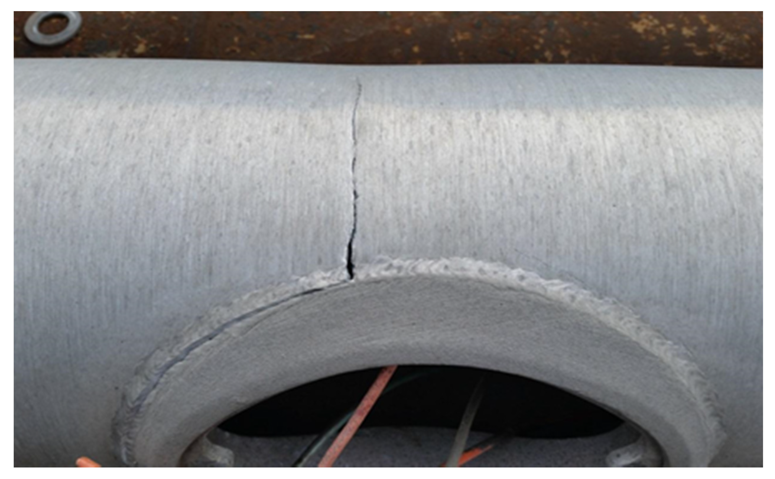
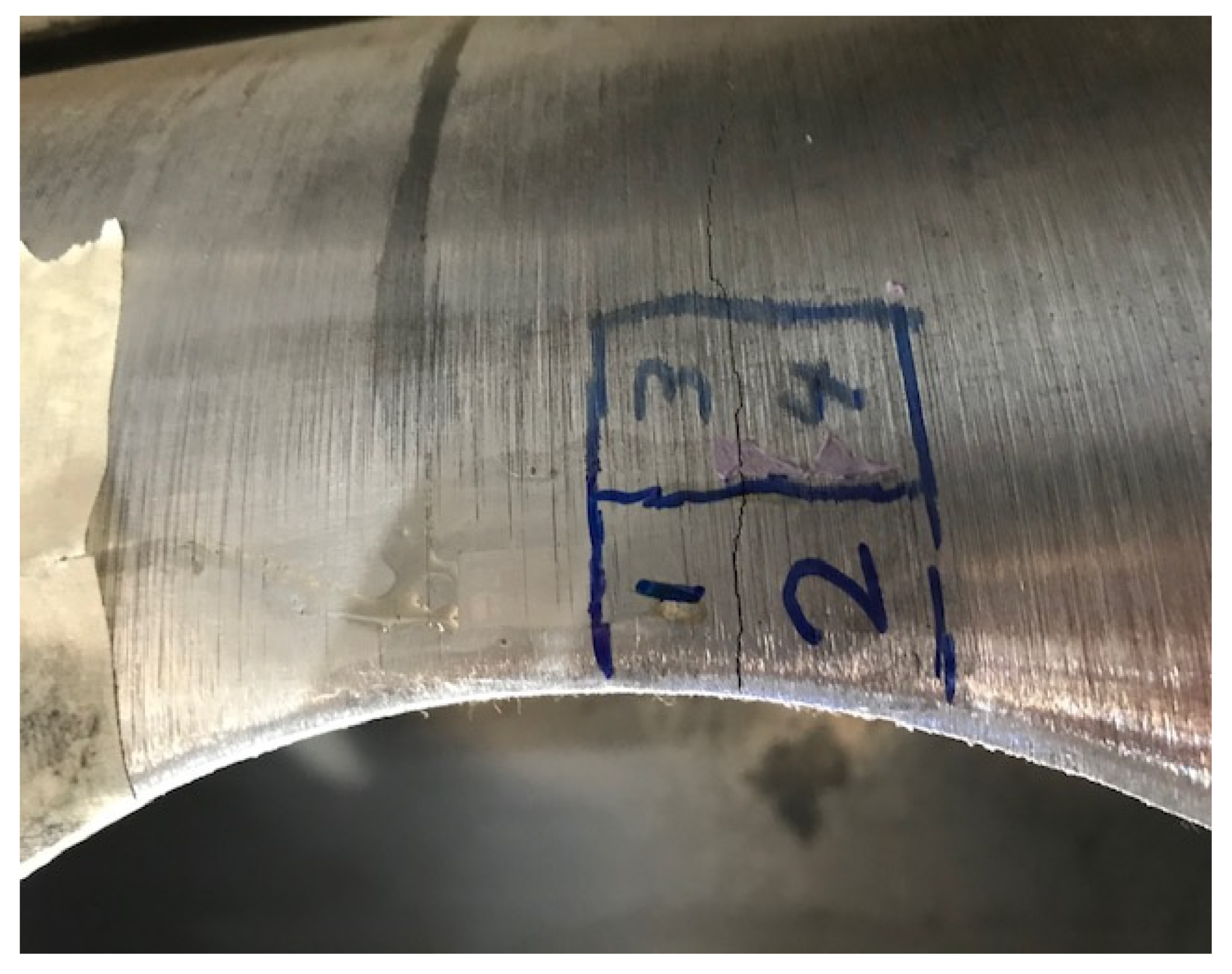
Field observations have shown that some hand-hole details are susceptible to failure due to fatigue cracking. NCHRP report number 469 [5] described these fatigue cracks of welded steel structures near the hand-hole in multiple states. These included California, New Mexico, New York, and Minnesota. Subsequent inspections of different poles occurred after the failure of a high mast light pole in Iowa. It was found that another tower had crack associated with the hand-hole. Cracks were found in some of the aluminum light poles along the Mullica River Bridge after a violent storm in 2011 [7]. A picture of one of these failures was taken and can be seen in Figure 1.
At the University of Akron, a study was conducted on 20 light-pole specimens, with fatigue tests conducted under bending loads. In addition to fatigue test, several static ones were conducted in order to see how the strain distributed around the hand-hole. This study found that the data from the welded hand-hole fatigue tests fell above the category D and E design S-N curves of the Aluminum Design Manual [8]. Another study found that the change in diameter of the pole has a modest effect on the fatigue life. In this companion study, seven eight-inch poles with 14 details were tested [9].
Nine aluminum light poles, each containing two separate hand-holes, were tested in fatigue under four-point bending. All poles were supplied to the University of Akron and were manufactured to standards typical for the industry. Finite element models were created to help improve the understanding of the stress concentrated around the hand-holes. The models created had different aspect ratios.
2. Materials and Methods
2.1. Pole Geometry and Material Properties
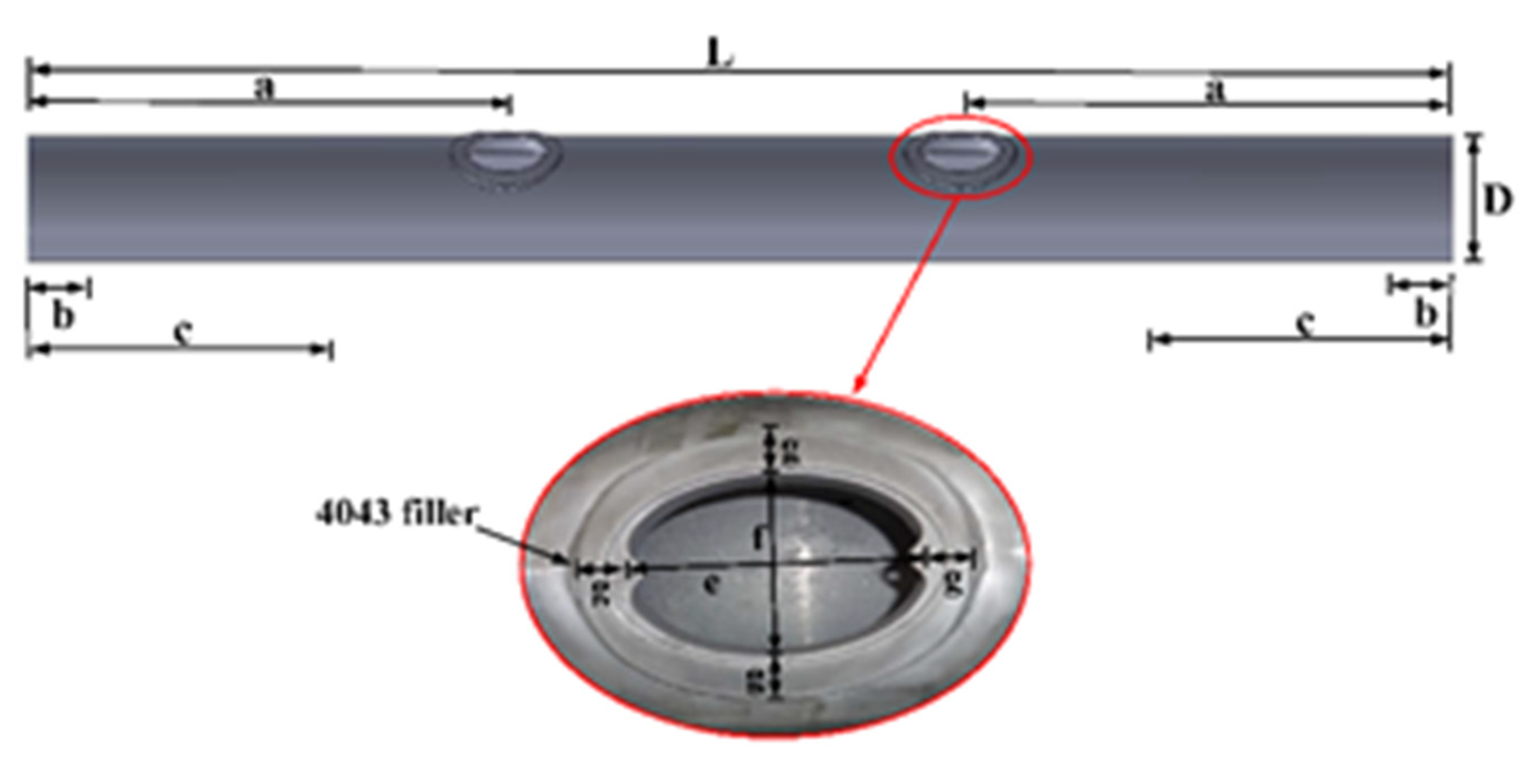
Nine aluminum light poles were tested under cyclic loading to examine the behavior of the unreinforced hand-hole. These specimens consisted of a 10 in (25.4 cm) diameter aluminum alloy extruded tube with a ¼ in (0.635 cm) thick wall. Each of the tubes was fabricated from aluminum alloy 6063. Typically, there is a reinforcement welded into the hand-hole opening, but these tests used only open holes (Figure 2). Hand-holes measured 6 in (150 mm) along the length of the pole in the longitudinal direction of the pole and 4 in (100 mm) in the transverse direction. Each specimen was 144 in (3.66 m), or 12 feet in length, with the hand-holes placed 54 in (1.37 m) in from either end. Support rollers for the specimens were inserted 6 in (15.2 cm) from each end [10].
Table 1 is a summary of the minimum mechanical properties of the aluminum tube.
2.2. Fatigue Tests
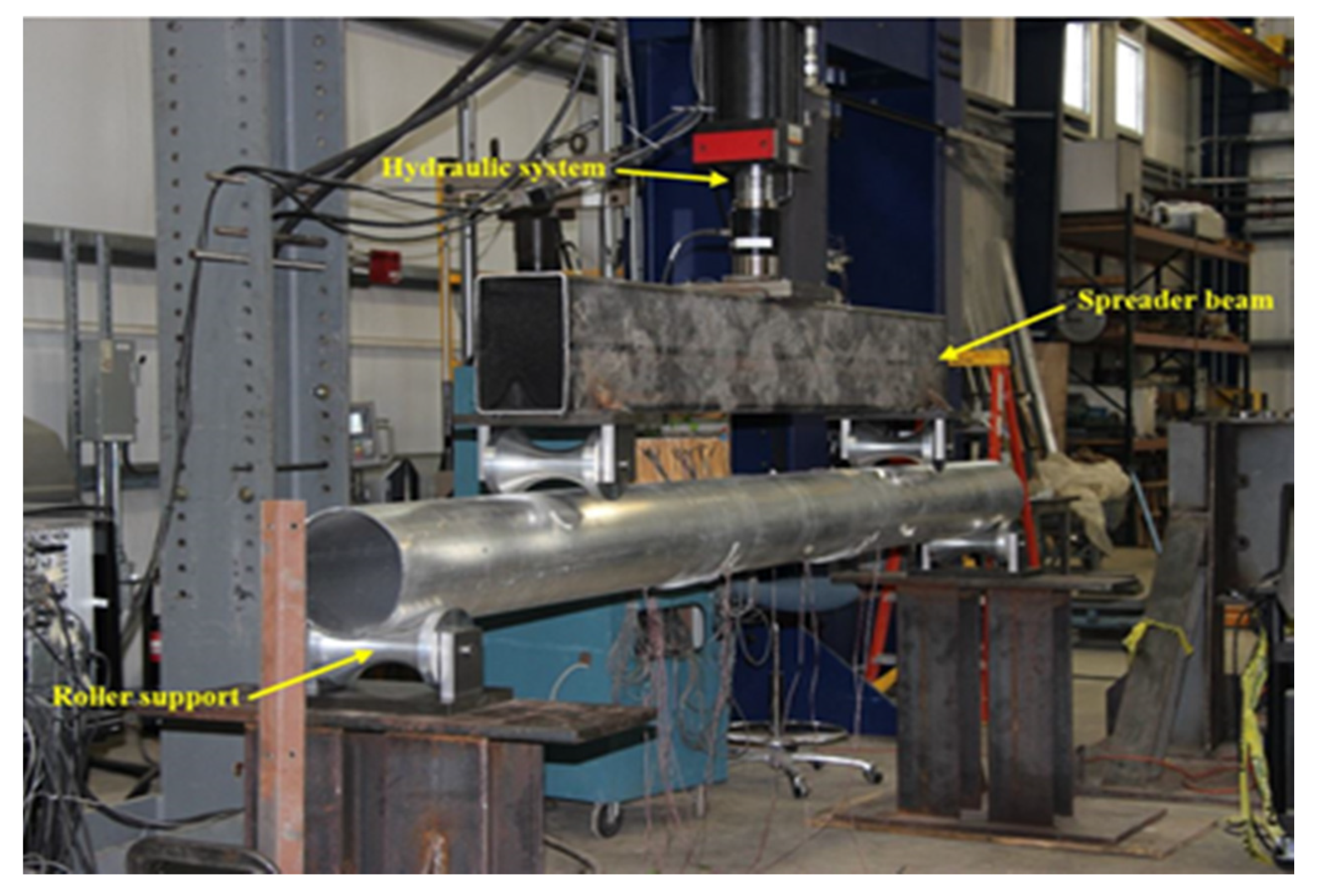
Figure 3 depicts a photo of the four-point bending fatigue test setup in the lab. During testing, a 55 kips (245 KN) MTS servo-hydraulic actuator (MTS Systems Headquarters, Eden Prairie, MN 55344, USA) along with a control system was used to apply the loads to the specimens. The actuator itself was mounted to a load frame capable of safely supporting 300 kips (1335 KN). Loads were applied to each of the specimens through a spreader beam that was attached to the hydraulic system. The supports the specimens rested on consisted of rollers that were machined to fit the cylindrical profile of the specimens.
Testing was conducted with a load control, while the strains were monitored using gages that were applied around the hand-holes, along with a single gage placed in the middle of the specimen. The typical location of the strain gages can be seen in Figure 4. Strain gages had a resistance of 350 ohms and were ⅛ in (3.175 mm) in length. Strain readings were taken every two hours intermittently for 10 seconds using a Micro-Measurements System 8000 data acquisition device (Micro-Measurements A VPG Brand Raleigh, NC 27611, USA) that was wired to the strain gages.
All of the specimens were oriented with the hand-holes facing downwards direction so that they were in tension during cyclic testing. Failure was achieved when the hand-hole region was cracked to the point that the loading on the specimen could no longer be supported. A maximum displacement was placed on the specimens for each of the fatigue tests to ensure that both hand-holes could be tested. The upper limit was set 10% larger than the maximum static displacement. When this maximum displacement was exceeded, the test would automatically shut down. Once this limit was reached and the test was stopped, the detail that failed was reinforced with a moment clamp. An image half of the moment clamp can be seen in Figure 5. Two halves were placed around the handhole and mechanically secured. The test was restarted and continued until the other hand-hole failed. With the specimen being loaded in four-point bending, the moment and hence applied stress does not change at the undamaged handhole after the moment clamp was applied. Of the nine specimens tested, only one resulted in a catastrophic failure where repair of the detail was not possible.
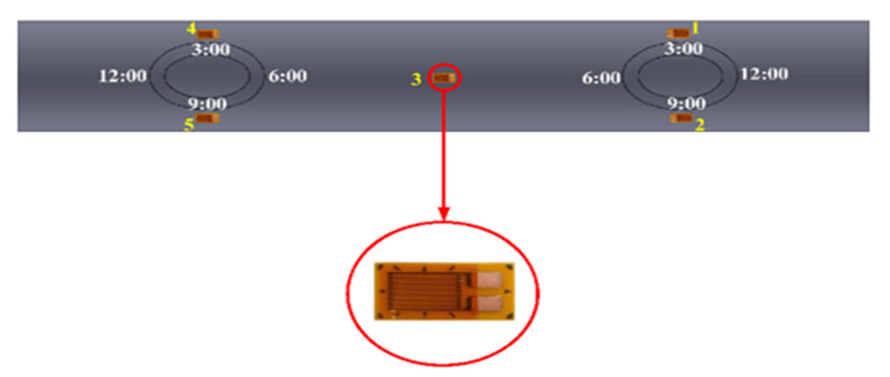
Nine poles, each with two hand-holes, were tested at stress ranges between 17.24 MPa (2.5 ksi) and 58.61 MPa (8.5 ksi). Figure 6 depicts a sketch of where the strain gages were installed adjacent to the hand-hole. Strain gages were placed at the 3 and 9 o’clock positions, with the addition of a strain gage in the middle of the specimen. This gage was within 2 to 3 times the tube thickness away from the edge of each hand-hole. All of the strain gages were wired to the data acquisition system to measure the applied strains. Five specimens were cycled at 1 Hz and four were cycled at 2 Hz. Testing continued around the clock. Visual inspections of the hand-holes were conducted daily.
2.3. Finite Element Models
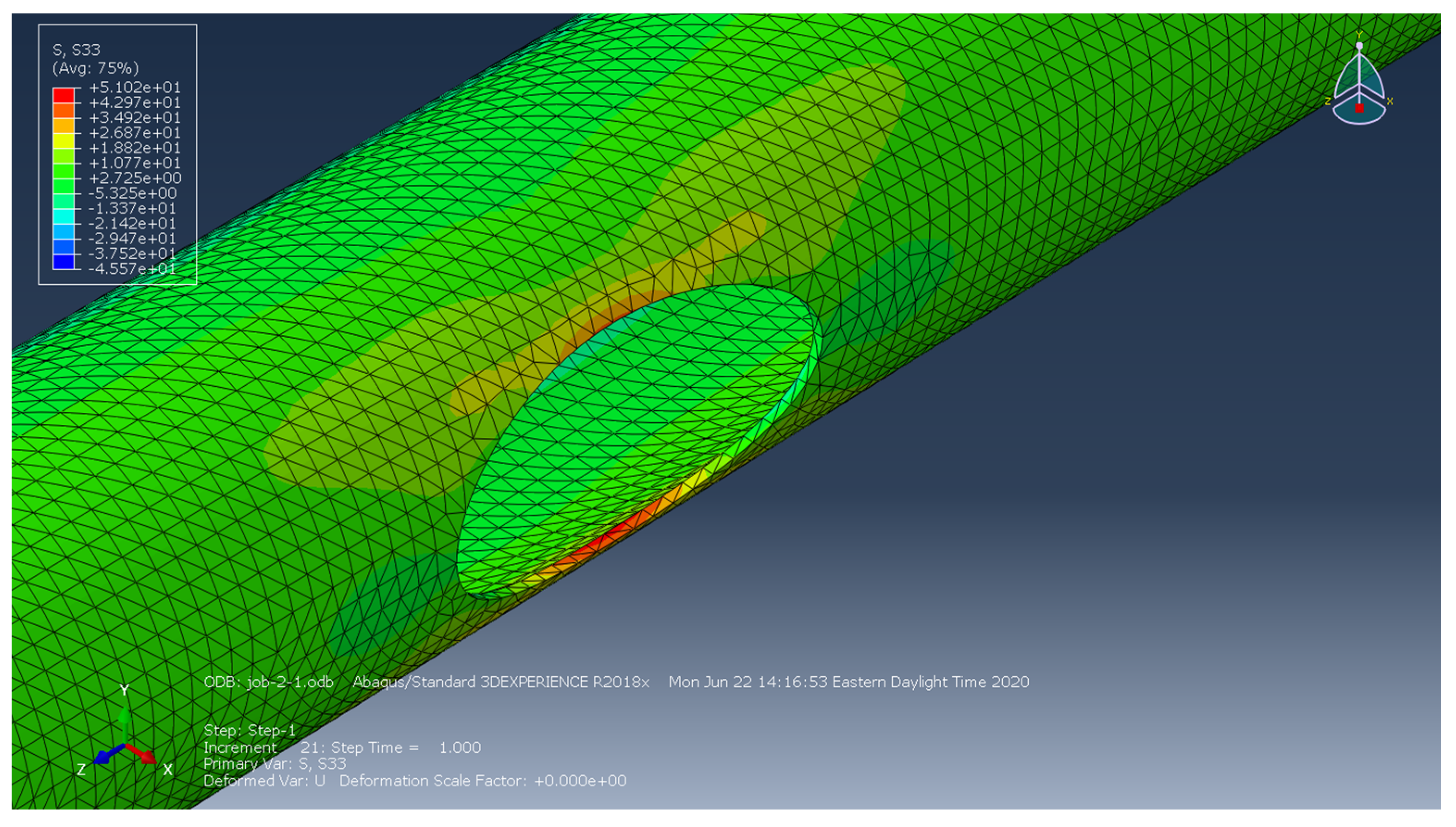
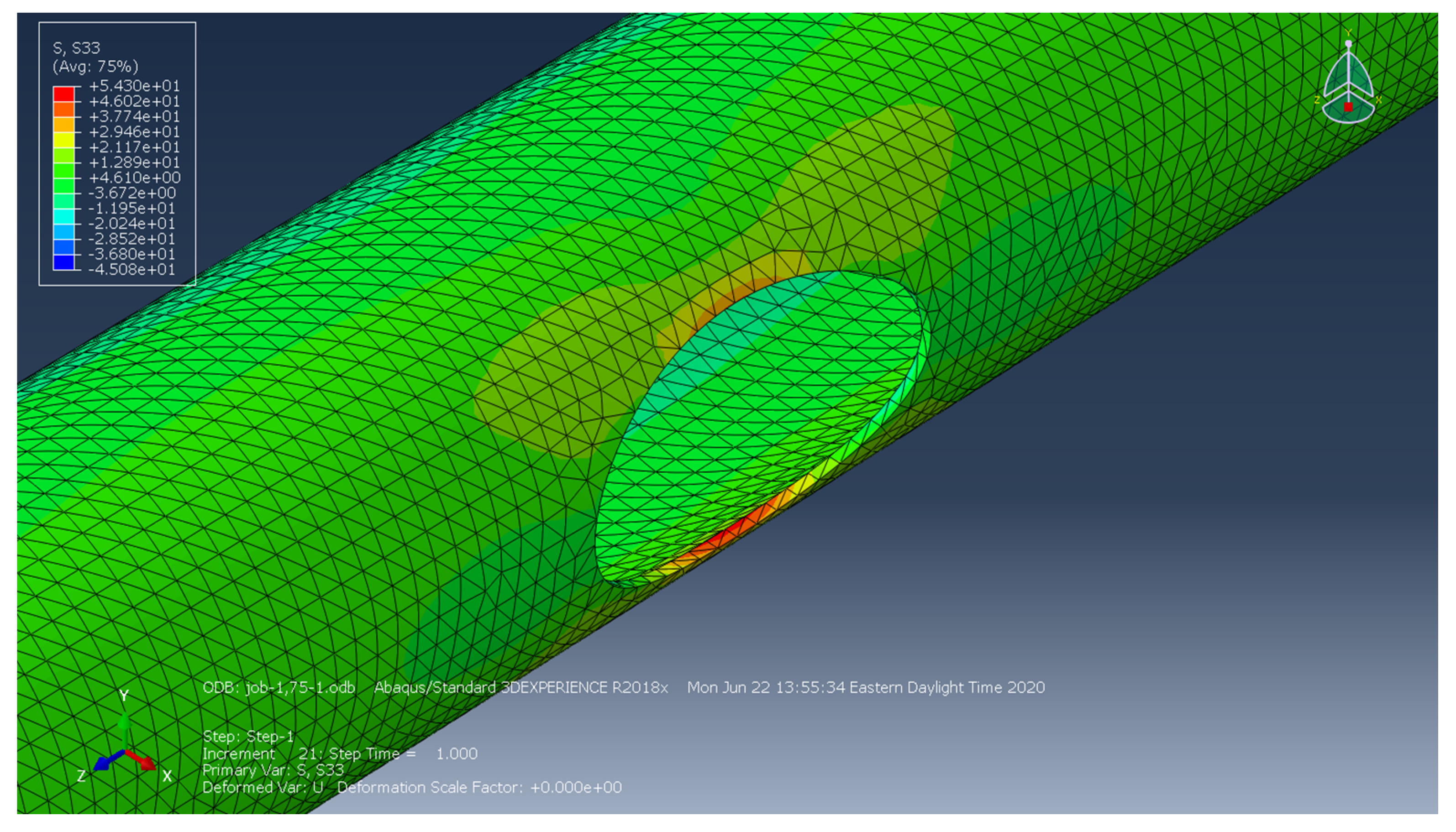
The finite element (FE) model was created for the four-point bending specimens in an attempt to gain a better understanding of the stress distribution around and adjacent to the hand-holes. All modeling was completed within Abaqus CAE (2018 version, Troy, MI 48084, USA). The material model was a general, linear elastic material with only the modulus of elasticity and Poisson’s ratio specified. The mechanical response and the influence of geometry on local stresses was the primary concern and focus of the FE analysis. As such, an advanced material model was not needed. Models were classified as “shell” models. Loading was applied by selecting the outermost nodes on the transverse plane where the rollers made contact with the pole. In the model, 365 individual nodes were selected, with a concentrated load of 0.01926 N of force applied to each. A total of 7.03 N was applied to the tube where the rollers were located. Multiple models were created with different aspect ratios. These included 2-1, 1.75-1, 1.5-1, 1-1, 1-1.25, and 1-1.5. The aspect ratio was calculated by dividing length of the hand-hole by the transverse dimension of the handhole. The purpose of the analyses was to determine whether a change in the aspect ratio had any effect on the local stress distribution around the hand-hole. Local stresses were mesh-dependent for this study. A finer mesh size typically increases the stresses local to important geometric details, whereas a more course mesh often results in a reduction in local stresses. The elements in the model consisted of a mix of both hexahedral and tetrahedral element types. Figure 7 depicts the mesh of the 1.5-1 model. In the field, the hand-holes with reinforcement have an aspect ratio of 1.5-1.
3. Results
3.1. Fatigue Tests Results
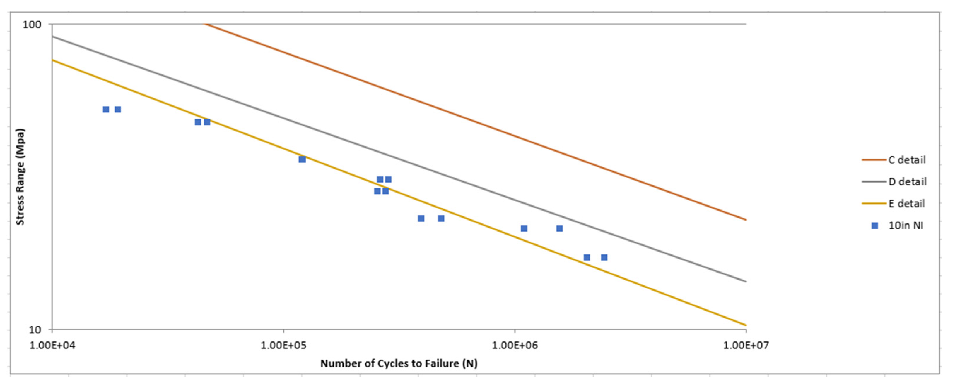
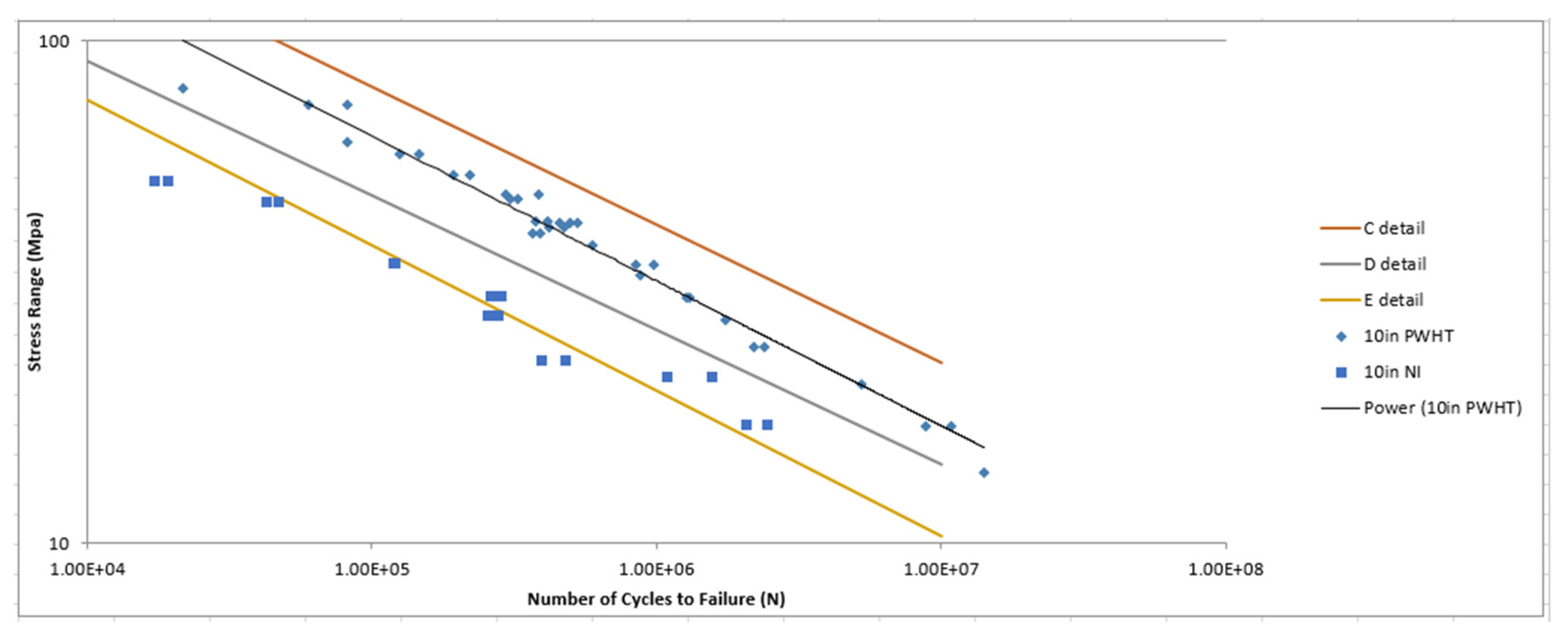
Of the 18 hand-holes tested, 17 failed, with the results shown in Figure 8.
All of the fatigue test data appears to follow the lower bound “E detail” S-N curve, even though the handholes themselves were not reinforced. Additional data would be needed to establish a lower bound for the unreinforced handholes but would be expected to be lower than Category E. Figure 9 shows a comparison between no insert specimens and a previous study conducted on reinforced hand-holes in 10 in diameter poles. This figure clearly demonstrates the benefit of having the welded reinforcement around the hand-holes [11].
During fatigue testing, cracks were observed at either the 3:00 or 9:00 position along the minor axis of the hand-hole. Typically, these cracks would initiate and then propagate transversely into the pole from the point of origin. Cracks would become visible and quickly progress into the pole, followed by failure. Figure 10 depicts a fatigue crack at the 3:00 position.
3.2. Finite Element Results
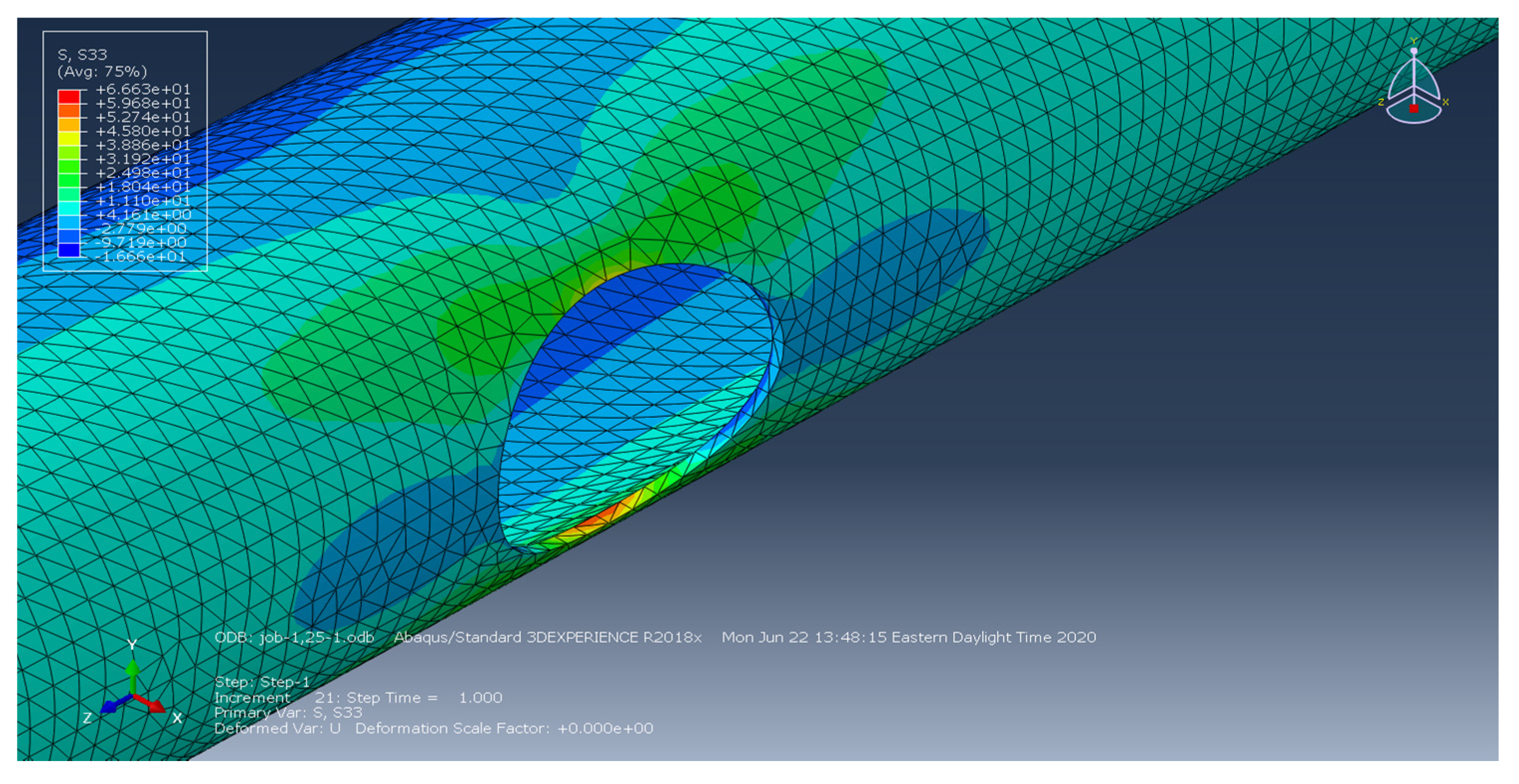
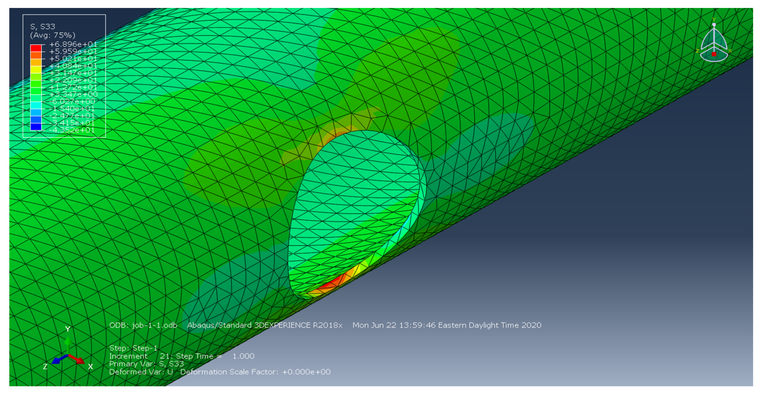
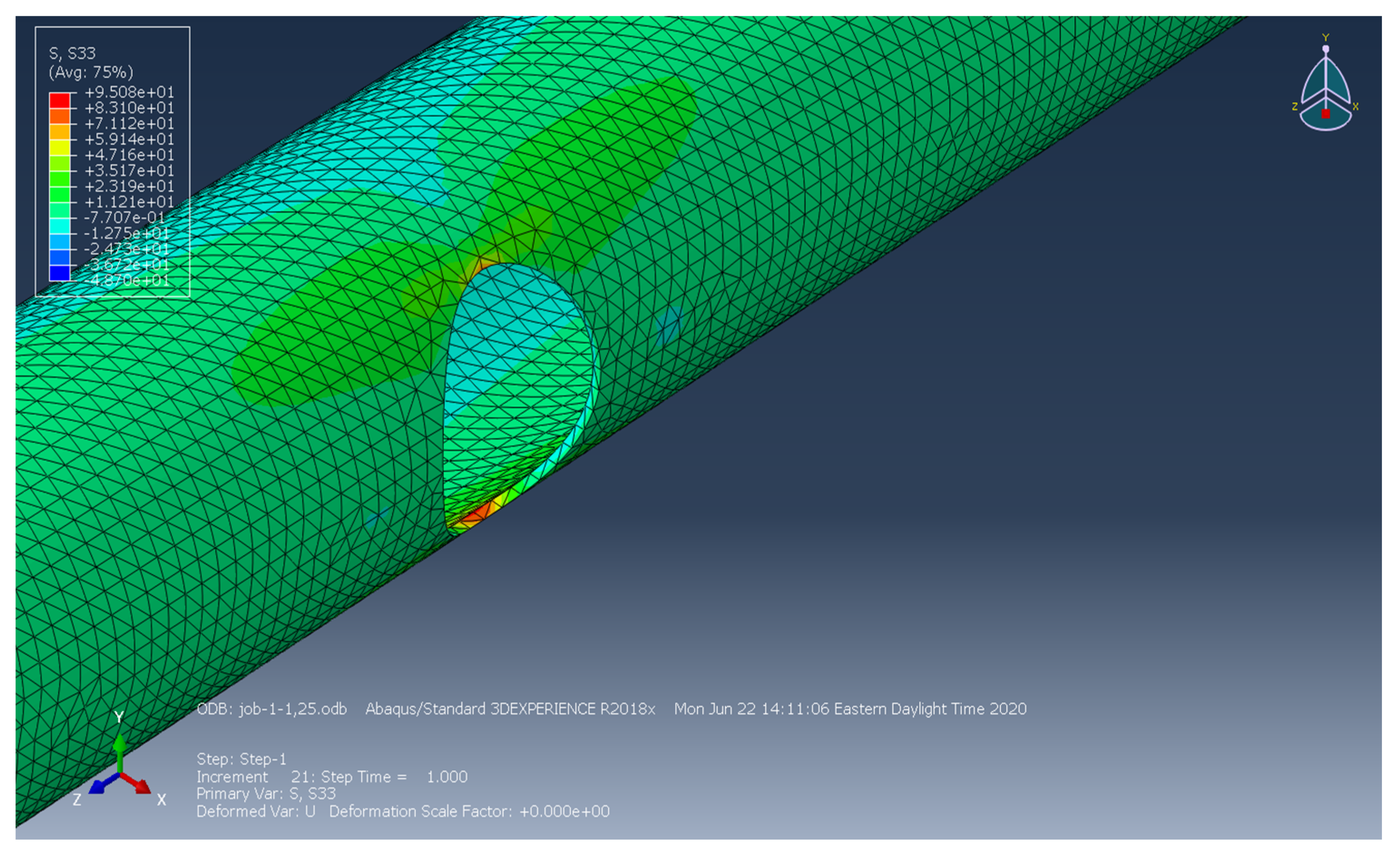
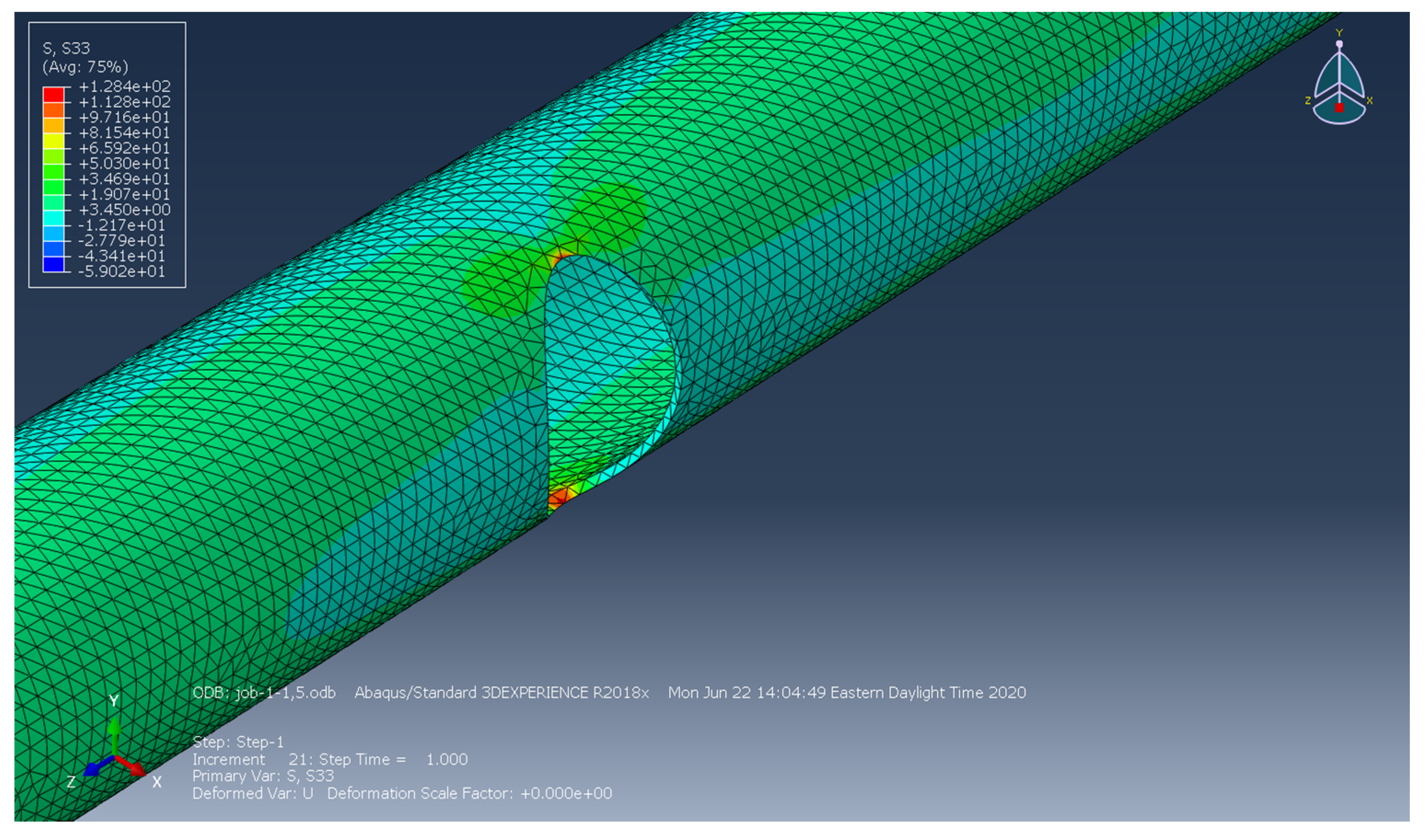
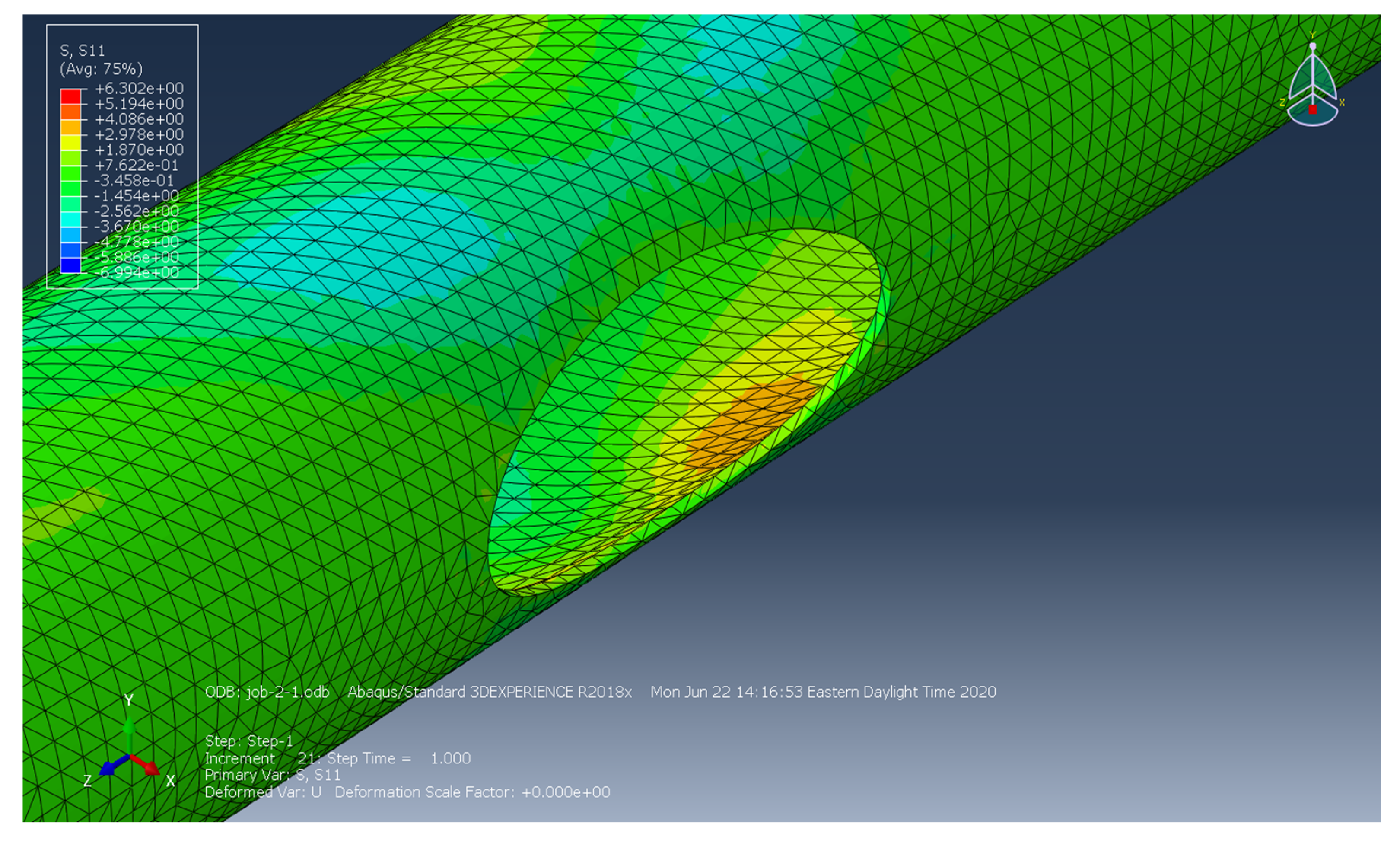
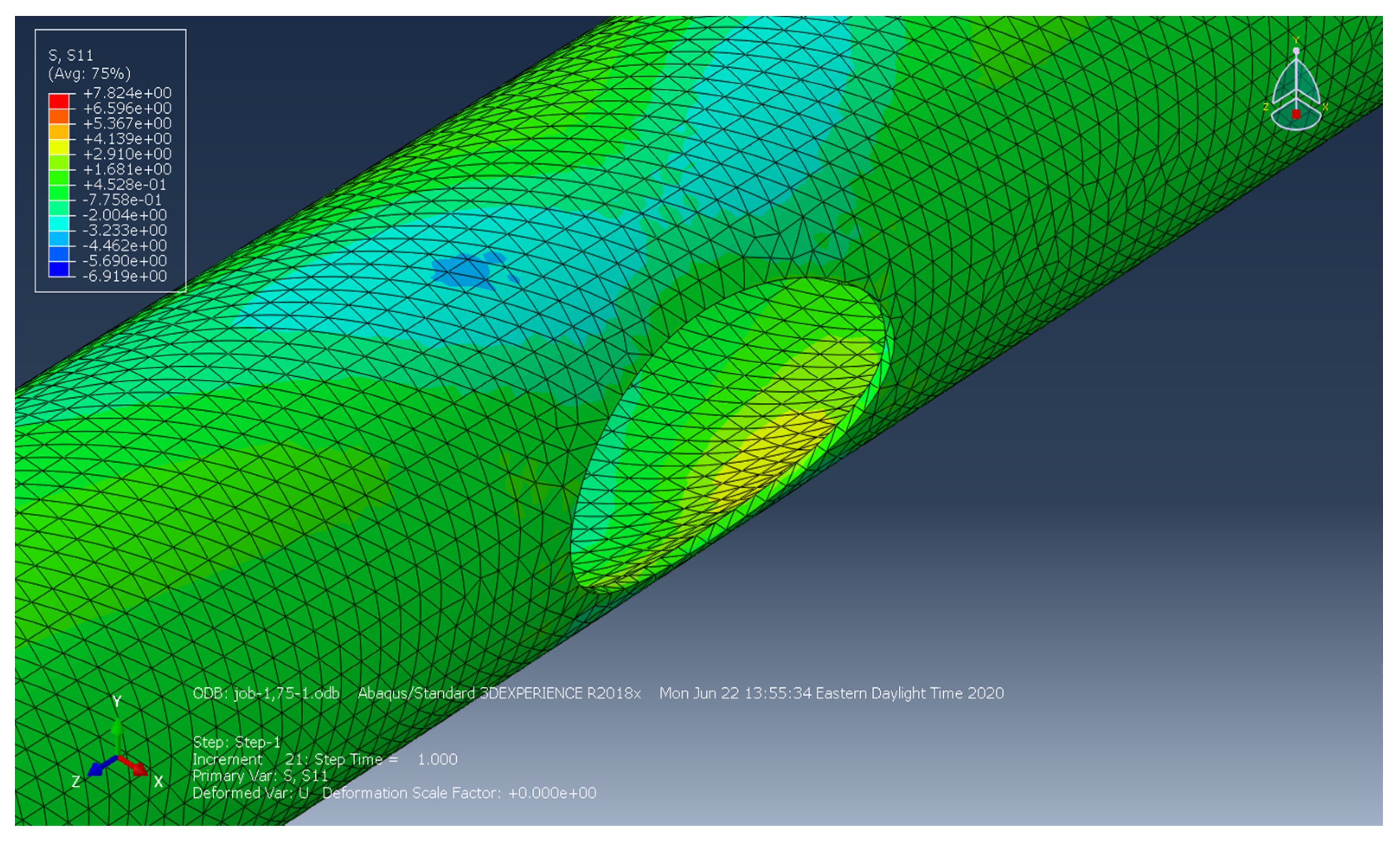
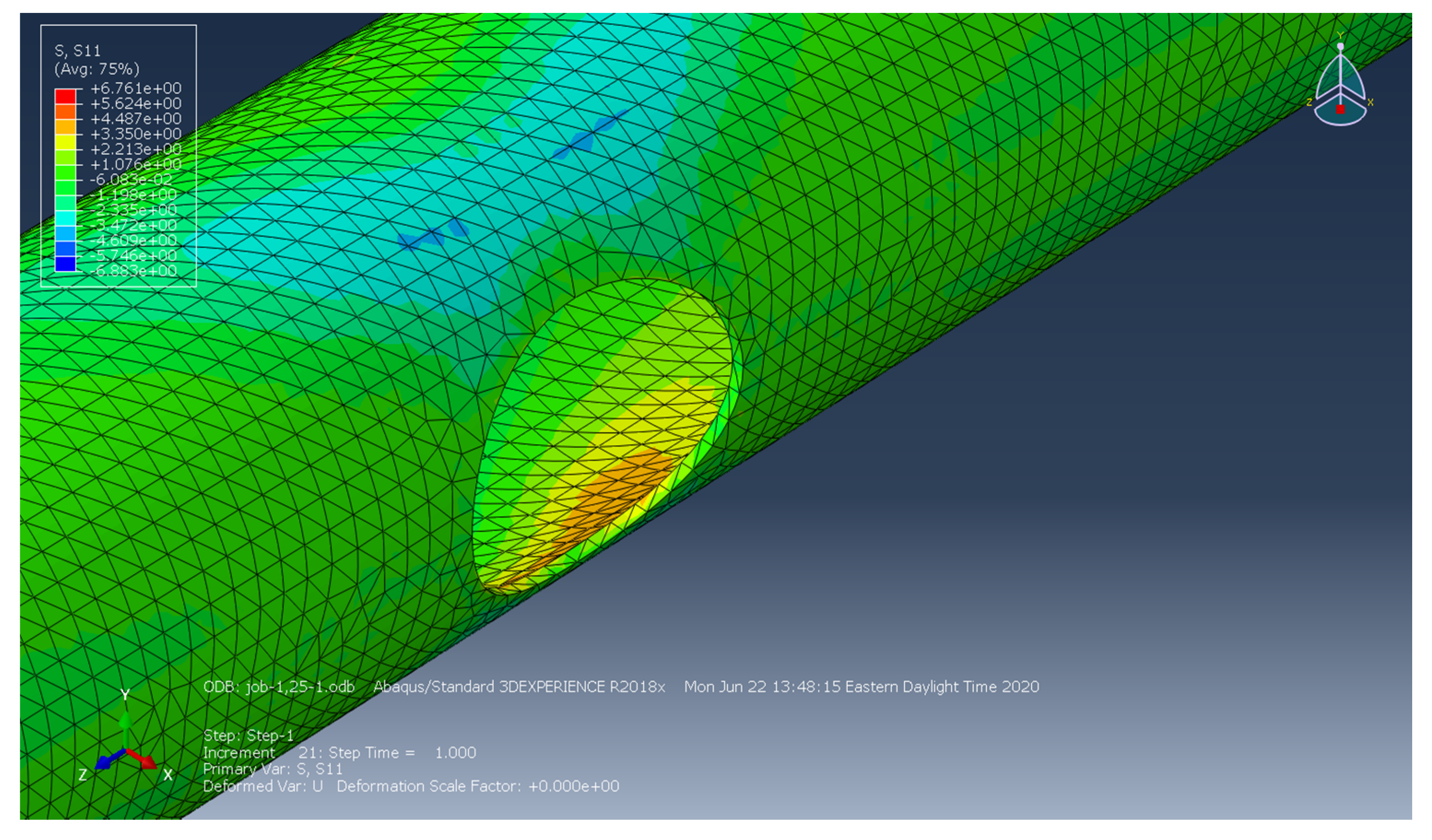
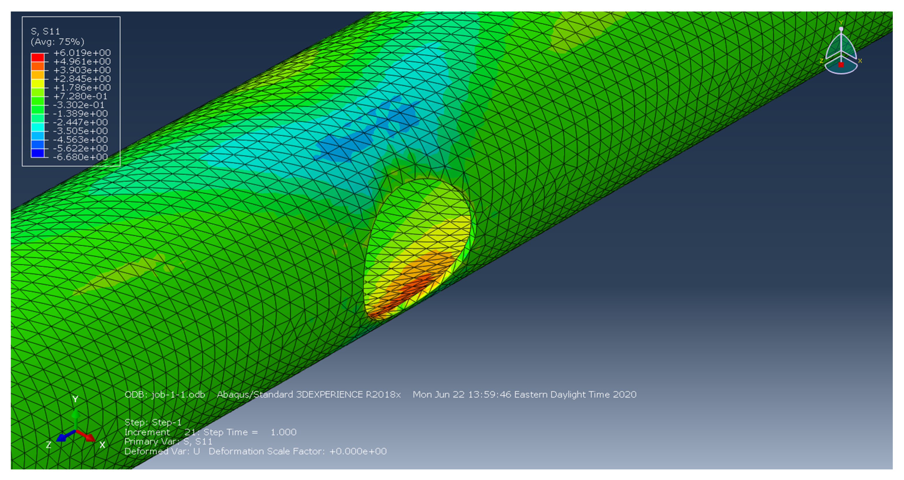
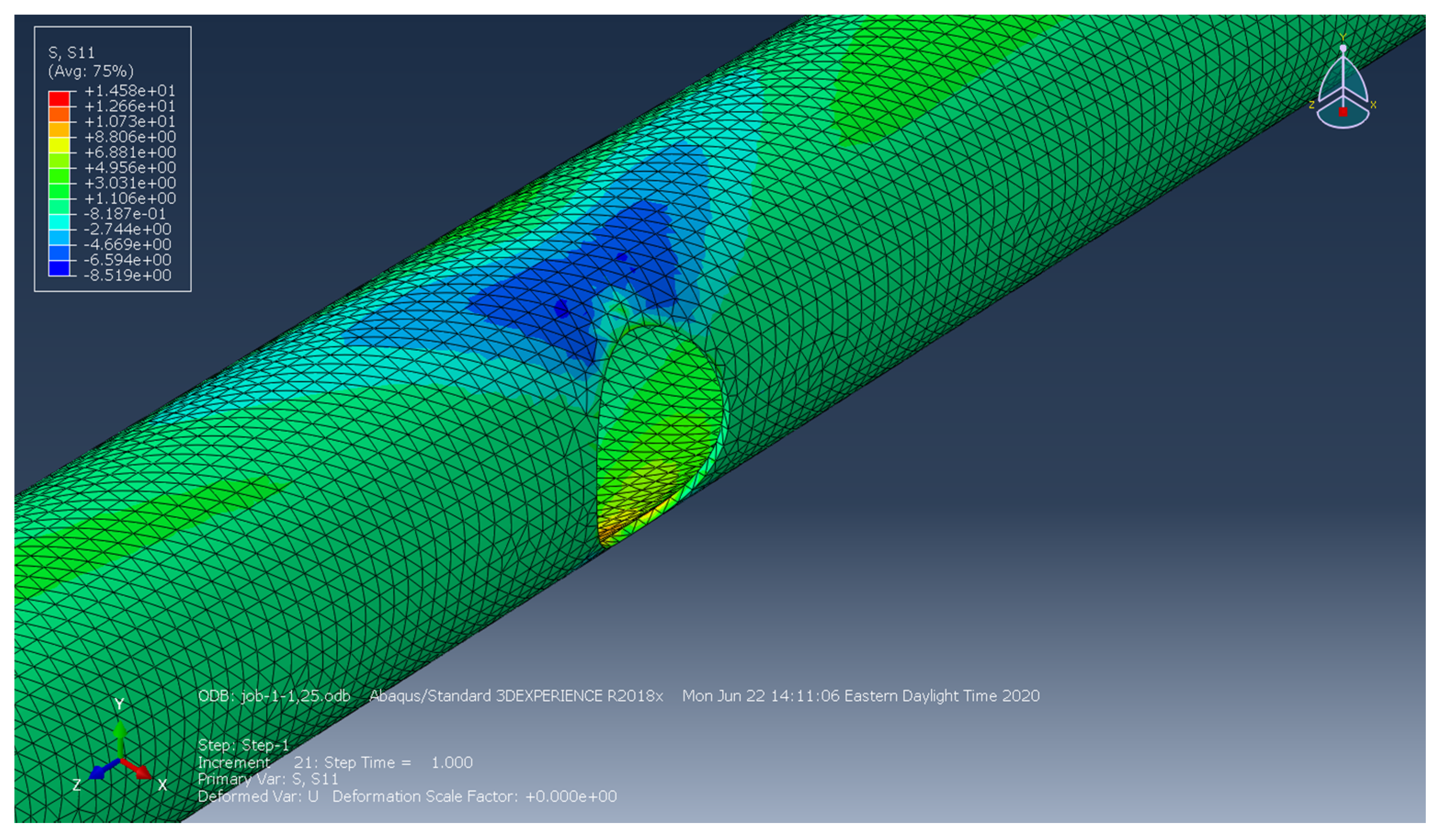
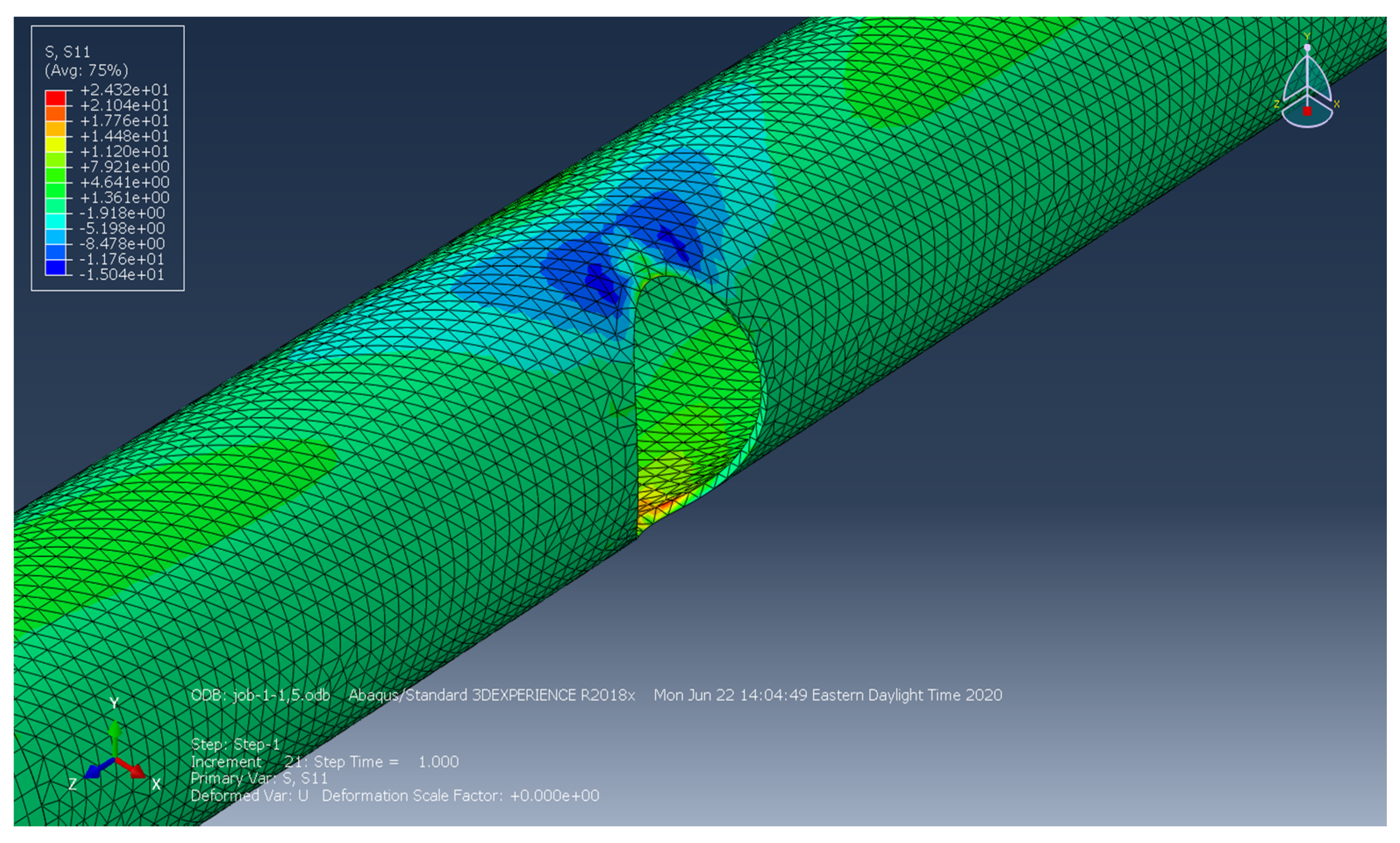
“Hot spots” are generally as local areas with elevated stresses and provide an indication where fatigue cracks may develop. Figure 11, Figure 12, Figure 13, Figure 14, Figure 15 and Figure 16 depict the stress contour maps along the Z-axis (longitudinal stress) for handholes with different aspect ratios. In all cases, hot spots were most prevalent at either the 3:00 or 9:00 position. The stress concentrations make sense due to how the loading is applied and how the hand-holes themselves are simply an opening within the specimen. The maximum stress increased as the aspect ratio changed from 2–1 to 1–1.5.
Figure 17, Figure 18, Figure 19, Figure 20, Figure 21 and Figure 22 show the maximum transverse stresses along the X-axis (transverse stress) around the hand-holes with different aspect ratios. The transverse stresses follow the same pattern as the longitudinal, with the 1-1.5 aspect ratio having the largest local stresses and the 2-1 having the mildest. These figures also show how stress accumulates inside of the pole apart from the hand-hole opening itself.
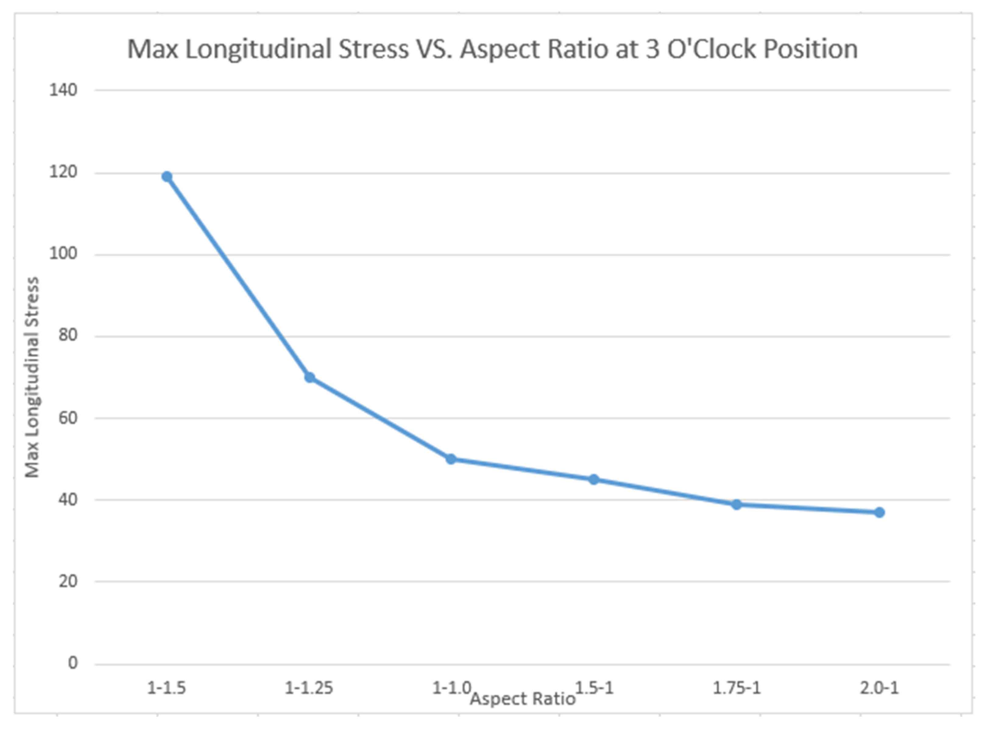
The maximum longitudinal stress was plotted against the aspect ratio in order to gain a better understanding of how the aspect ratio affects the local stress. The area was taken along the inside of the hand-hole at the 3:00 position. This location was chosen as this spot contained some of the largest stresses (Figure 23). Table 2 accompanies Figure 23 and provides not only longitudinal stresses, but transvers as well. Table 2 shows that the transverse stress was negligible at the location of interest, near the 3:00 position.
4. Conclusions
Four-point bending fatigue tests were conducted on aluminum light pole containing no reinforcement. Tests revealed that there was a negative effect on the fatigue life when the cast reinforcement was removed. This was most evident when the stress range was higher. This can be seen from Figure 9 from Section 3. A total of nine tests were conducted, resulting in 17 data points, stressed at various different stress ranges. Finite element models showed how different hand-hole aspect ratios affect the stress concentration. While a hand-hole aspect ratio of 2-1 may provide the lowest local longitudinal stress, it may not be the most practical out in the field. It is unknown how a hand-hole with an aspect ratio of 2-1 would behave if reinforced.
Author Contributions
For the duration of, C.R.R. did the conceptualization, methodology, software utilization, validation, formal analysis, investigation, resources, data curation, writing of the original draft, visualization with C.C.M. writing in the form of reviewing and editing. All authors have read and agreed to the published version of the manuscript.
Funding
This research was funded by HAPCO Light Pole Products.
Data Availability Statement
Not applicable.
Conflicts of Interest
The authors declare no conflict of interest.
References
- Murthy, M.V.V.; Rao, K.P.; Rao, A.K. On stresses around an arbitrarily oriented crack in a cylindrical shell. Int. J. Struct. 1974, 10, 1243–1269. [Google Scholar] [CrossRef]
- Durelli, A.J.; Parks, V.J.; Feng, H.C. Stresses around an elliptical hole in a finite plate subjected to axial loading. J. Appl. Mech. 1966, 33, 192–195. [Google Scholar] [CrossRef]
- The Aluminum Association. Aluminum Design Manual: Specification for Aluminum Structures; The Aluminum Association: Arlington, VA, USA, 2010. [Google Scholar]
- Fisher, J.W.; Kulak, G.L.; Smith, I.F.C. A Fatigue Primer for Structural Engineers; National Steel Bridge Alliance & AISC: Chicago, IL, USA, 1998. [Google Scholar]
- Roy, S.; Park, Y.C.; Sause, R.; Fisher, J.W.; Kaufmann, E.J. Cost-effective connection details for highway sign, luminaire, and traffic signal structures. In NCHRP 10-70 Web-Only Doc. 176; Transportation Research Board: Washington, DC, USA, 2011. [Google Scholar]
- AASHTO (American Association of State Highway and Transportation Officials). Standard Specifications for Structural Supports for Highway Signs, Luminaires and Traffic Signals (LRFDLTS-1); AASHTO (American Association of State Highway and Transportation Officials): Washington, DC, USA, 2015. [Google Scholar]
- Dexter, R.J.; Ricker, N.J. Fatigue-Resistant Design of Cantilevered Signal, Sign, and Light Supports. In NCHRP Report 469; University of Minnesota: Minneapolis, MN, USA, 2002. [Google Scholar]
- Menzemer, C. Examination of Several Mullica River Bridge Light Poles, Corresponding to J; Bowman, Hapco: Abingdon, VA, USA, 2012. [Google Scholar]
- Daneshkhah, A.R.; Schlatter, C.R.; Rusnak, C.R.; Menzemer, C.C. Fatigue behavior of reinforced welded hand-holes in aluminum light poles. Eng. Struct. Mater. 2019, 188, 60–68. [Google Scholar] [CrossRef]
- Rusnak, C.R. Fatigue Behavior in Reinforced Electrical Access Holes in Aluminum Light Pole Support Structures. Master’s Thesis, The University of Akron, Akron, OH, USA, 2019. [Google Scholar]
- Hilty, E.; Menzemer, C.; Manigandan, K.; Srivatsan, T. Influence of welding and heat treatment on microstructure, properties and fracture behavior of a wrought aluminum alloy. Emerg. Mater. Res. 2014, 3, 230–242. [Google Scholar] [CrossRef]
Figure 1.
Aluminum light pole containing a fatigue crack within the field.

Figure 2.
Typical geometry of a welded aluminum hand-hole detail in four-point fatigue testing. (In this study there was no welded detail). (L = 3.66 m (144 in); D = 25.4 cm (10 in); a = 1.37 m (54 in); b = 15.2 cm (6 in); e = 150 mm (6 in); f = 100 mm (4 in)).
Figure 2.
Typical geometry of a welded aluminum hand-hole detail in four-point fatigue testing. (In this study there was no welded detail). (L = 3.66 m (144 in); D = 25.4 cm (10 in); a = 1.37 m (54 in); b = 15.2 cm (6 in); e = 150 mm (6 in); f = 100 mm (4 in)).

Figure 3.
Four point bending fatigue test set-up.

Figure 4.
Typical strain gage location and position around the hand-holes.

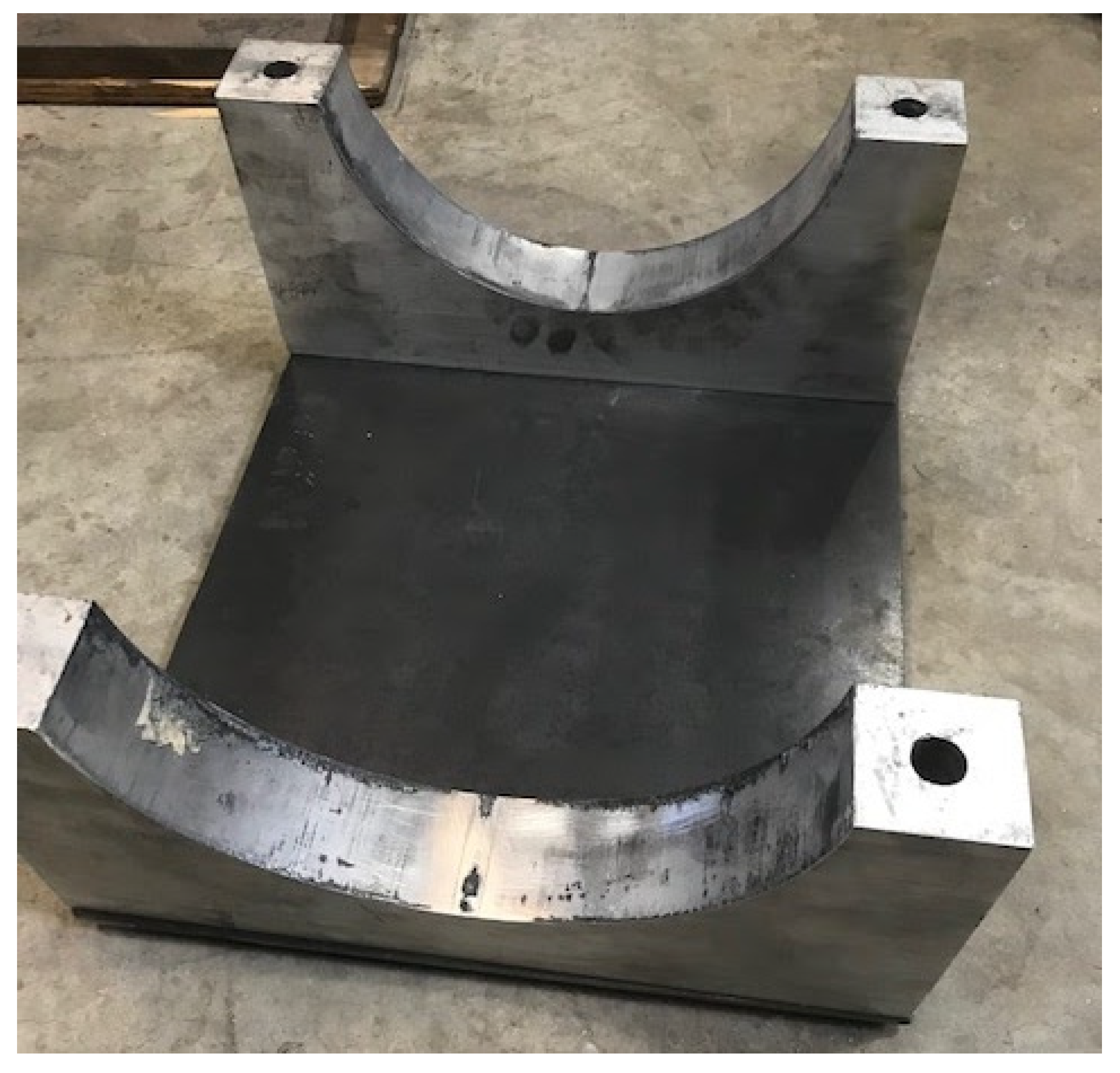
Figure 5.
Half of the moment clamp used to reinforce the hand-hole after initial failure.

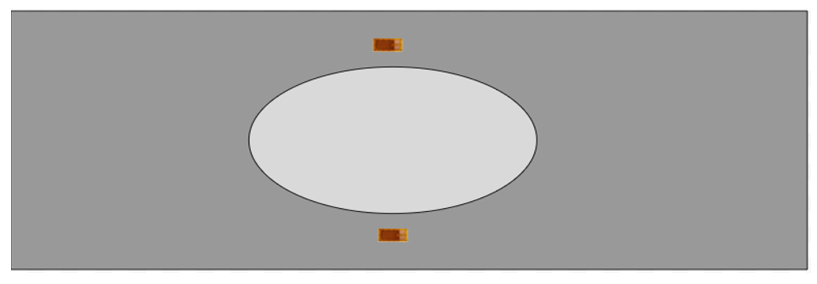
Figure 6.
The position of strain gages installed around a hand-hole.

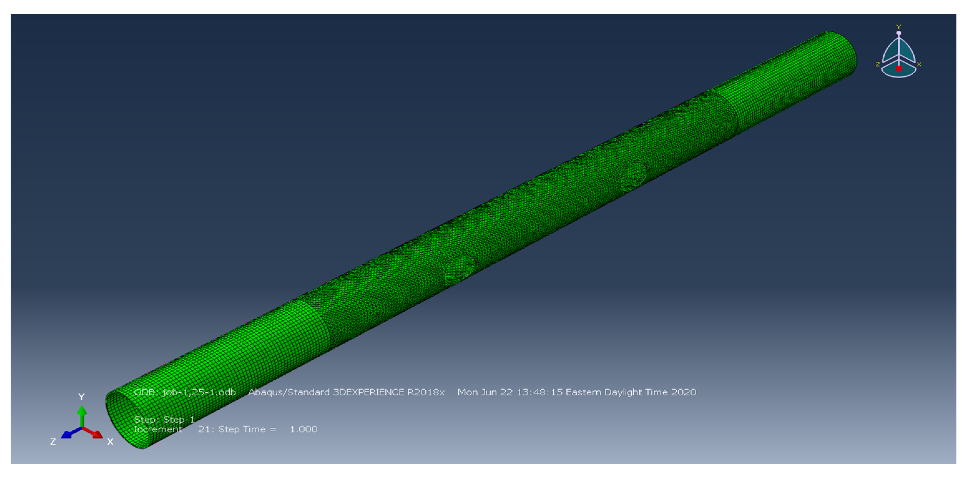
Figure 7.
Overall FE model of 1.5-1.

Figure 8.
Fatigue test results.

Figure 9.
No insert detail vs. old 10 in data.

Figure 10.
Fatigue crack through pole.

Figure 11.
Aspect ratio 2-1 in longitudinal (Z) direction.

Figure 12.
Aspect ratio 1.5-1 in longitudinal (Z) direction.

Figure 13.
Aspect ratio 1.25-1 in longitudinal (Z) direction.

Figure 14.
Aspect ratio 1-1 in longitudinal (Z) direction.

Figure 15.
Aspect ratio 1-1.25 in longitudinal (Z) direction.

Figure 16.
Aspect ratio 1-1.5 in longitudinal (Z) direction.

Figure 17.
Aspect ratio 2-1 in transverse (X) direction.

Figure 18.
Aspect ratio 1.5-1 in transverse (X) direction.

Figure 19.
Aspect ratio 1.25-1 in transverse (X) direction.

Figure 20.
Aspect ratio 1-1 in transverse (X) direction.

Figure 21.
Aspect ratio 1-1.25 in transverse (X) direction.

Figure 22.
Aspect ratio 1-1.5 in transverse (X) direction.

Figure 23.
Max longitudinal stress vs. aspect ratio.


Table 1.
Mechanical properties of the aluminum tube.
| Part Name | Alloy | Tensile Yield Strength | Ultimate Tensile Strength |
|---|---|---|---|
| Tube | 6063-T6 | 213.7 MPa (31 ksi) | 241.3 MPa (35 ksi) |
Table 2.
Longitudinal and transverse stress at the 3 o’clock position for the different aspect ratios.
Table 2.
Longitudinal and transverse stress at the 3 o’clock position for the different aspect ratios.
| Aspect Ratio | Longitudinal | Transverses |
|---|---|---|
| 1-1.5 | 118.8 | 5.0 |
| 1-1.25 | 72.0 | 0.9 |
| 1-1 | 48.4 | 0.1 |
| 1.5-1 | 44.0 | 0.0 |
| 1.75-1 | 38.5 | 0.0 |
| 2-1 | 36.7 | 0.1 |
Publisher’s Note: MDPI stays neutral with regard to jurisdictional claims in published maps and institutional affiliations. |
© 2021 by the authors. Licensee MDPI, Basel, Switzerland. This article is an open access article distributed under the terms and conditions of the Creative Commons Attribution (CC BY) license (https://creativecommons.org/licenses/by/4.0/).
Share and Cite
MDPI and ACS Style
Rusnak, C.R.; Menzemer, C.C. Fatigue Behavior of Nonreinforced Hand-Holes in Aluminum Light Poles. Metals 2021, 11, 1222. https://doi.org/10.3390/met11081222
AMA Style
Rusnak CR, Menzemer CC. Fatigue Behavior of Nonreinforced Hand-Holes in Aluminum Light Poles. Metals. 2021; 11(8):1222. https://doi.org/10.3390/met11081222
Chicago/Turabian StyleRusnak, Cameron R., and Craig C. Menzemer. 2021. "Fatigue Behavior of Nonreinforced Hand-Holes in Aluminum Light Poles" Metals 11, no. 8: 1222. https://doi.org/10.3390/met11081222
Note that from the first issue of 2016, this journal uses article numbers instead of page numbers. See further details here.