Article

X-ray Radiography Inspection of Pores of Thin Aluminum Foam during Press Forming Immediately after Foaming

1
Graduate School of Science and Technology, Gunma University, Kiryu 376-8515, Japan
2
Joining and Welding Research Institute, Osaka University, Ibaraki 567-0047, Japan
3
Applied Mechanical Engineering Section, Gunma Industrial Technology Center, Maebashi 379-2147, Japan
*
Author to whom correspondence should be addressed.
Metals 2021, 11(8), 1226; https://doi.org/10.3390/met11081226
Submission received: 19 June 2021 / Revised: 19 July 2021 / Accepted: 28 July 2021 / Published: 31 July 2021
(This article belongs to the Special Issue Advances and Applications in Cellular Metals)

Abstract

:
Forming aluminum foam to the desired shape while retaining its pore structures is essential for manufacturing aluminum foam products. Recently, a press forming process for aluminum foam that is performed after precursor foaming but before solidification has been proposed. In this study, to track individual pores throughout press forming immediately after foaming, X-ray radiography inspection was applied. A thin precursor was used, and foaming was constrained to the X-ray transmission direction. It was shown that, although some pores coalesced with other pores, the pores did not collapse during press forming. In addition, the porosity of aluminum foam evaluated from X-ray transmission images was constant during press forming. Some pores retained their shape during press forming but their position was changed by the material flow generated by press forming. These results show that by press forming before the solidification of aluminum foam, aluminum foam can be shaped without the collapse of pores.

1. Introduction

Products with high functionality and reduced weight are essential in many industries such as the automobile and construction industries. Aluminum foam has low density, allowing it to float on water, with excellent energy absorption and vibration damping characteristics [1,2]. To meet the requirements of various industrial fields, it is indispensable to form aluminum foam with the desired shape. It is difficult to shape aluminum foam by a general cutting process because the collapsed cell walls fill the surface pores, resulting in a dense aluminum layer [3,4,5].
A precursor foaming process has been developed for manufacturing aluminum foam products [6,7]. In this foaming process, solid aluminum containing foaming agent powder is prepared as the precursor in advance. Next, the precursor is placed in a mold and then foamed by heat treatment. The foaming agent powder decomposes and releases gas during heat treatment. The foamed precursor fills the mold and acquires its shape [8,9]. A problem with this foaming process is that the mold is also heated, resulting in excessive power consumption. In addition, using the mold makes it difficult to control the temperature of the precursor during foaming. This is because changes in precursor temperature are delayed owing to the heating and cooling processes first affecting the mold. The delay in cooling before the solidification of aluminum foam induces the coarsening and coalescence of the pores of aluminum foam. Furthermore, unmolding is necessary after cooling.
Recently, the press forming of aluminum foam immediately after foaming but before solidification has been proposed [10,11,12]. In this forming process, the precursor can be directly heated because of the absence of the mold, and the cooling rate is high owing to the use of a cold die as the press-forming die. In addition, press forming is a high-productivity process. Furthermore, immediately after foaming the foamed precursor is soft enough for press forming with a lower force than that used in the general compression of aluminum foam at room temperature. Generally, pores collapse during the formation of aluminum foam [13,14,15], similarly to the one observed [16,17,18]. In contrast, the surface of the die can be transferred to the aluminum foam while retaining the pores by press forming immediately after foaming [10]. In our previous study [11], X-ray transmission was attempted as a means of observing pores during press forming to confirm their retention without collapsing during press forming. However, several pores overlapped in their projection on X-ray transmission images. In particular, when the direction of X-ray transmission was perpendicular to that of press forming, the number of pores gradually increased during press forming, which was induced by the expansion of aluminum foam caused by the material flow. Therefore, it was difficult to track individual pores and to evaluate porosity throughout press forming.
In this study, a thin precursor was foamed while constraining foaming to the X-ray transmission direction so that only one or two non-overlapping pores appeared during press forming, which could be easily observed without overlapping. X-ray radiography inspection was carried out to observe the movement of individual pores and the change in porosity during press forming. Moreover, to confirm that the X-ray radiography inspection process can be used to clearly observe individual pores, X-ray computed tomography (CT) inspection was applied to the aluminum foam.

2. Experimental

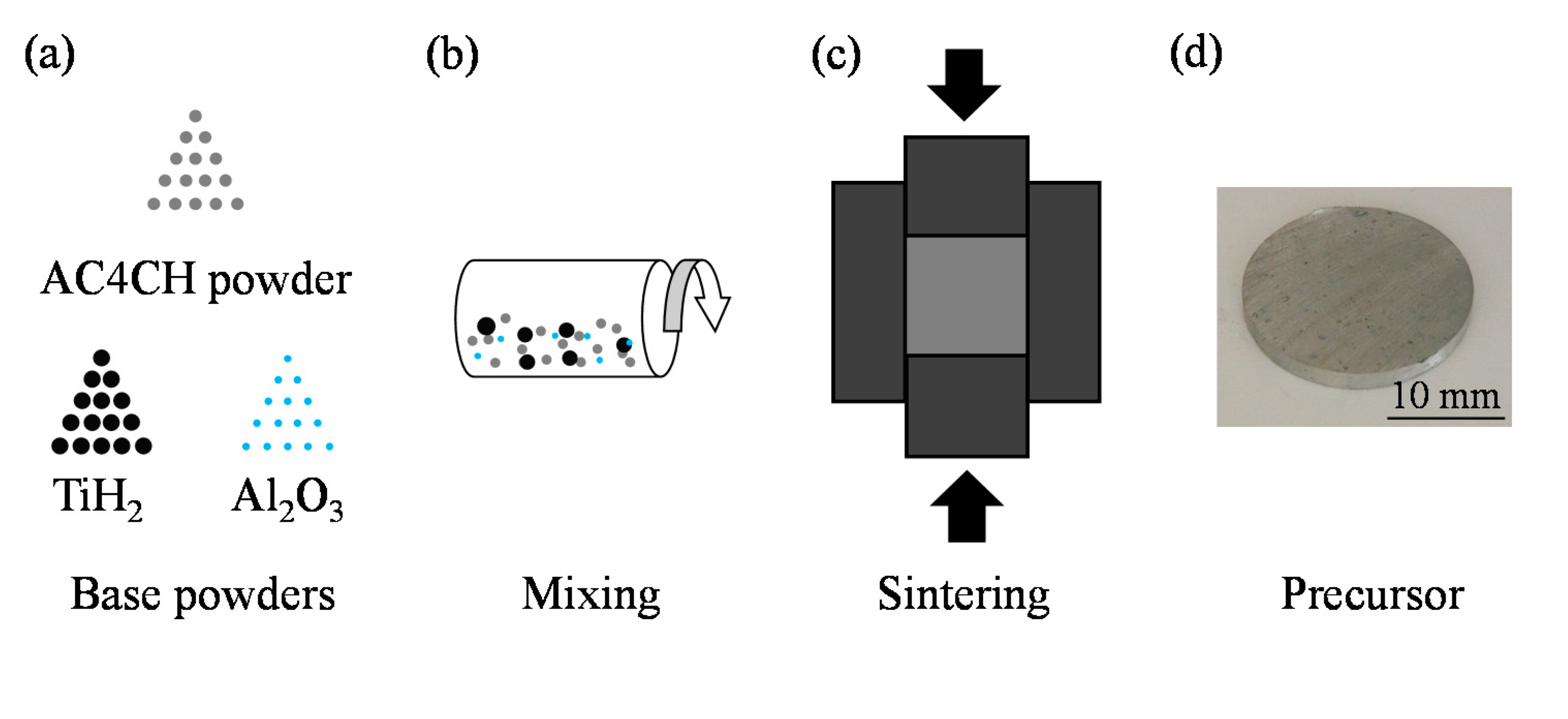
2.1. Precursor of Aluminum Foam

The precursor was prepared by the powder metallurgy route as shown in Figure 1. As shown in Figure 1a,b, Al-Si-Mg (AC4CH) alloy powder, titanium hydride (TiH2) powder as a foaming agent, and alumina (Al2O3) powder as a thickening agent were first mixed. The AC4CH powder (Toyo Aluminium K.K., Osaka, Japan), TiH2 powder (Kojundo Chemical Lab. Co., Ltd., Sakado, Japan), and Al2O3 powder (Kojundo Chemical Lab. Co., Ltd.) had particle sizes of approximately 25 μm, less than 45 μm, and approximately 1 μm, respectively. The amounts of TiH2 and Al2O3 powders were 1 mass% and 5 mass%, respectively, with respect to the mass of AC4CH powder, in accordance with the work in [19]. Then, as shown in Figure 1c, the mixed powder was sintered using spark plasma sintering (SPS) equipment. The holding temperature was 520 °C, the holding time was 5 min, and the holding pressure was 50 MPa, in accordance with the work in [20]. Then, a sintered mixture with a diameter of 20 mm and a height of 20 mm was obtained, and then cut to obtain a precursor with a diameter of 20 mm and a thickness of 3 mm, as shown in Figure 1d.

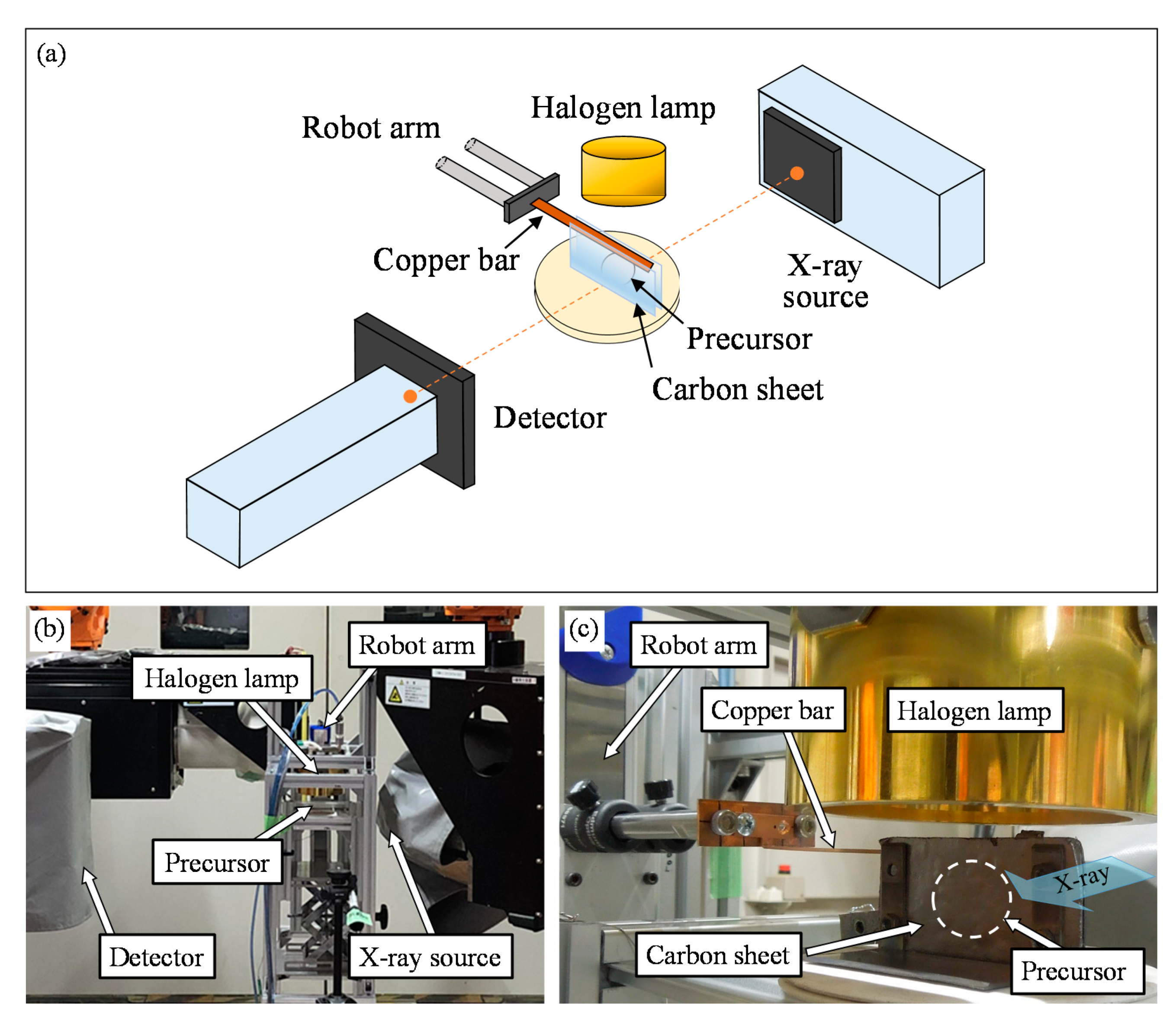
2.2. X-ray Radiography Inspection

An image and photograph of the setup for observing pores during press forming is shown in Figure 2a,b. An X-ray transmission system, which Morisada et al. [21,22] adopted to observe the material flow during friction stir welding (FSW), was used for the observation. The equipment for precursor foaming and press forming was introduced between the X-ray source and the detector, which were placed horizontally. The tube voltage and tube current of the X-ray source were 40 kV and 4.5 mA, respectively. The resolution of the obtained images was 960 × 1280. The frame rate of the scanning was 50 fps. The precursor was placed between two 1-mm-thick carbon sheets, which were held by a copper jig to constrain a thin aluminum foam during foaming and press forming as shown in Figure 2c. The precursor was placed on the copper plate to adjust the height of the precursor so that it could be clearly observed by X-ray transmission imaging during foaming and press forming. Then, they were placed on a ceramic plate. The carbon sheets were used because of their high thermostability and sufficient strength to constrain the precursor in the thickness direction and easily transmitted X-rays. This precursor with the carbon sheets was heat treated using a 2 kW halogen lamp from above. The current and voltage were approximately 15 A and 80 V, respectively, throughout the experiment. After the precursor had sufficiently foamed, the X-ray irradiation began, then press forming was conducted using a copper bar with a thickness of 1 mm and a width of 3 mm. The width of the copper bar was similar to the distance between the two carbon sheets to enable the copper bar to be easily placed between the carbon sheets and to move down. During press forming, the copper bar was moved down by a robot arm (Single Axis Robots RS2; MISUMI Group Inc., Tokyo, Japan) at 7 mm/s to form a 7-mm-height aluminum foam. Then, the X-ray irradiation was stopped and the lamp was turned off. The press-formed aluminum foam was cooled between the carbon sheets with the copper bar kept in contact with the foam. After the aluminum foam had sufficiently solidified, X-ray transmission began again and an X-ray transmission image of the solidified aluminum foam was obtained. The same experiment was conducted on two samples (Samples I and II, hereinafter). In addition, a sample that was only foamed between the carbon sheets without press forming was fabricated.

2.3. X-ray CT Inspection

The obtained aluminum foam was subjected to X-ray CT observation after it had solidified and been taken out from the carbon sheets. As the copper bar was embedded in the aluminum foam and could not be removed, X-ray CT inspection was conducted on the foam including the copper bar. An SMX-225CT micro-focus X-ray CT system (Shimadzu Corporation, Kyoto, Japan) was used for the observation with X-ray tube voltage and current of 80 kV and 30 μA, respectively. The voxel size of the obtained X-ray CT images was 114 μm. Cross-sectional X-ray CT images in the desired direction were obtained by using image processing software.

3. Results and Discussion

3.1. Foaming without Press Forming

By constraining foaming using carbon sheets, a thin aluminum foam was obtained as shown in Figure 3a, which shows the aluminum foam without press forming. The thickness of the Al foam measured by a caliper was 4.54 mm (average of ten points). The slight foaming for the thickness direction was considered to be the deformation of carbon sheets. Figure 3b shows the X-ray transmission image of the foam at the end of the heat treatment. Dark gray areas show cell walls and light gray areas show pores. Figure 3c shows a cross-sectional X-ray CT image of the aluminum foam obtained after solidification observed from the same direction as in Figure 3b. Gray areas show cell walls and black areas show pores. Although the X-ray transmission image has a slightly lower resolution than the X-ray CT image, it was found that individual pores can be observed even by X-ray transmission imaging. For example, pores A and B shown by arrows in Figure 3c can also be seen in Figure 3b. Figure 3d shows the cross-sectional X-ray CT image in the thickness direction, which was obtained from above the sample in Figure 3c. Although the slight foaming occurred for the thickness direction, it can be seen that only one or two pores existed in the thickness direction. These images confirm that X-ray transmission can be used to observe individual pores by constraining the precursor to foam in the thickness direction.

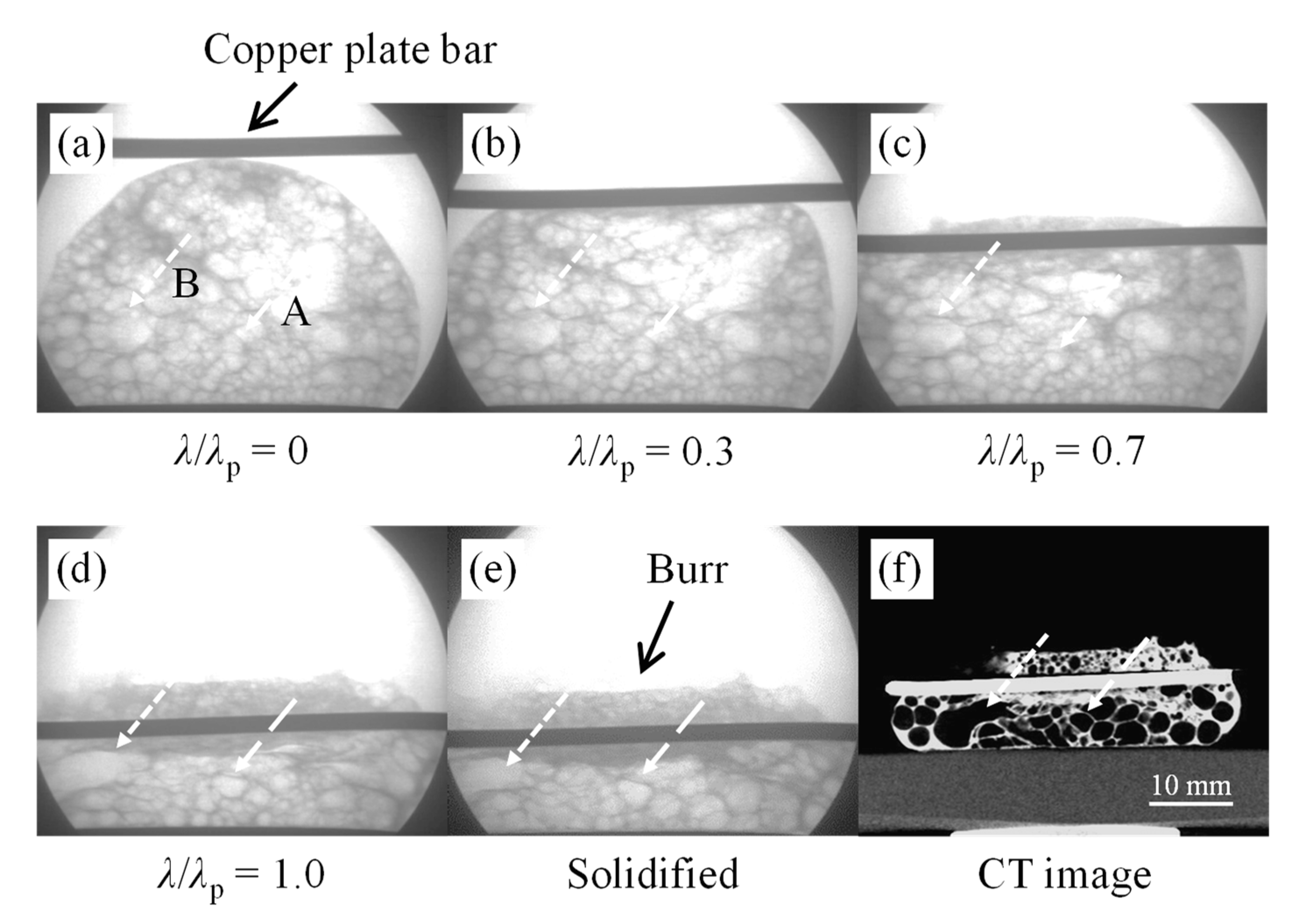
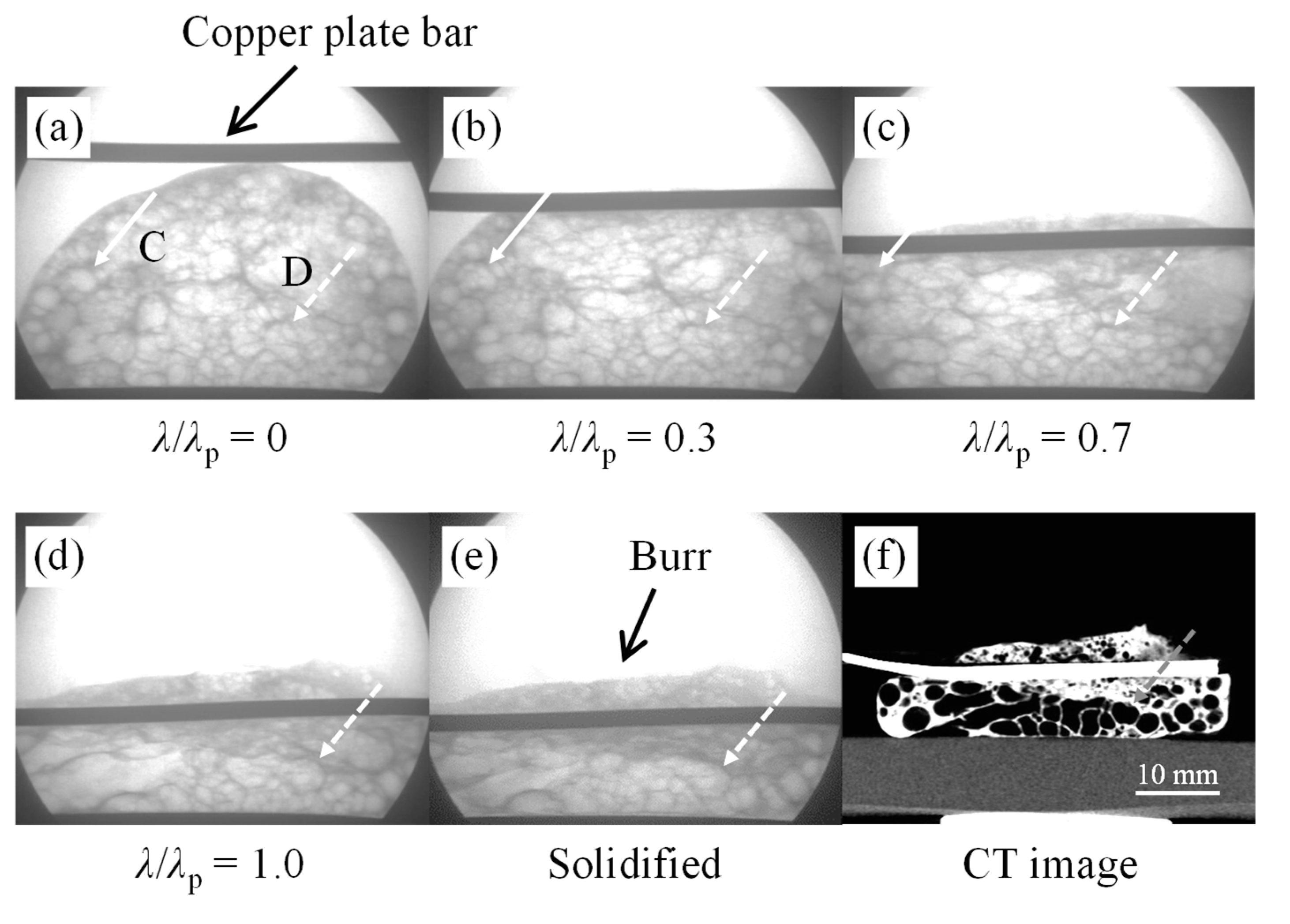
3.2. Observation of Pores during Press Forming

X-ray transmission images for Sample I taken during press forming are shown in Figure 4. Figure 4a shows the image obtained when press forming began after the precursor had sufficiently foamed and the copper bar (gray horizontal bar in the images) touched the aluminum foam. The precursor was sufficiently foamed even though it was covered with the carbon sheets and copper bar. The amount of press forming, λ, was defined as λ = 0 at this point and λ = λp at the end of press forming. Figure 4b–d shows sequential deformation images taken during press forming at λ/λp = 0.3, 0.7, and 1.0, respectively. It can be seen that the aluminum foam retained its pores without collapsing and expanded only laterally as a result of the material flow generated during press forming. Arrows in these images show examples of individual pores, which were tracked throughout press forming. Pore A retained its shape during press forming, but its position was changed by the material flow generated by press forming. Although pore B coalesced with other pores around λ/λp = 0.7–1.0, the pores did not collapse. In the general compression test of aluminum foam at room temperature, aluminum foam deforms with the collapse of pores [16,17,18]. In contrast, it was shown that by press forming before the solidification of aluminum foam, the aluminum foam deformed without the collapse of pores. Figure 4e shows an X-ray transmission image taken after the aluminum foam had sufficiently solidified. It was found that the pore shape slightly differed between Figure 4d,e. This indicated that the pore shape slightly changed during cooling until solidification. Figure 4f shows a cross-sectional X-ray CT image of the solidified aluminum foam taken from the same direction as Figure 4e. Although the field of view of the X-ray transmission image was small and part of the sample cannot be observed, it can be seen that the pore structures observed by X-ray transmission (Figure 4e) corresponded to those observed by X-ray CT (Figure 4f). Note that a burr with a dense part was generated around the copper bar. This was due to the gap between the copper bar and the carbon sheets during press forming. It is considered that the burr can be minimized by adjusting the press-forming die in actual production.
The X-ray transmission images taken during the press forming of another sample (Sample II) are shown in Figure 5. Pores C and D changed their position during press forming without collapsing, although pore C had moved out of the image by the end of press forming. Pore D can be observed even after the solidification of the aluminum foam in Figure 5e, as well as in the X-ray CT image shown in Figure 5f. Note that some pores coalesced and became large during press forming and cooling. This is because the heat treatment continued during press forming. Therefore, the pores continued to grow and coalesce. In addition, the heating rate was lower than the general optical heating rate because the light was cut off by the carbon sheets and copper bar, and the precursor was heated by the transfer of heat from them. Furthermore, the cooling rate was low because the aluminum foam was surrounded by them. Therefore, the foaming and cooling behaviors were considered to be different from those of the general foaming process. Despite these issues, individual pores could be observed and tracked during press forming, and the pores were retained without collapsing during press forming.
Photographs of Samples I and II and their cross-sectional X-ray CT images in the thickness direction are shown in Figure 6. The upper part of the sample above the copper bar was the burr generated between the copper bar and carbon sheets during press forming. The thickness, tf, of Samples I and II measured by a caliper was 4.66 mm and 4.68 mm (average of ten points), respectively. The figure shows that press forming can be conducted without the generation of cracks in the aluminum foam, which indicates that ductile deformation was achieved by press forming immediately after foaming. This tendency is consistent with our previous study [11]. In addition, as shown in Figure 6b,d, only one or two pores existed in the thickness direction. Therefore, it is considered that individual pores can be observed by X-ray transmission as shown in Figure 4 and Figure 5.
The changes in the porosity p (%) of Samples I and II during press forming are shown in Figure 7. X-ray transmission images of Sample I for λ/λp = 0, 0.4, 0.8, and 1.0 are also shown. The actual porosity was difficult to obtain from the X-ray transmission images because of their low resolution, making it difficult to separate aluminum cell walls and pores. Therefore, the porosity was estimated from the average gray scale value of the analysis area enclosed in a box in the X-ray transmission images. First, the actual thickness of Al without pores, t, was estimated on the basis of the Lambert–Beer law [23] using the following equation:
t   ln ( I 0 I ) ,
where I0 and I are the transmission intensities before and after X-ray transmission for a sample. Here, we assumed that I0 was assigned the average grayscale value (220.4) estimated from the X-ray transmission image of the carbon sheets alone without the precursor (open beam), as shown in Figure 8a. The grayscale value was obtained using the image processing software ImageJ. For comparison, the average grayscale value (116.1) estimated from the X-ray transmission image of the 3-mm-thick precursor between the carbon sheets before foaming, as shown in Figure 8b, was obtained. Then, t was estimated using the gray scale value of the Al foam sample and p was defined as
p = t f t t f 100
where tf is the thickness of the Al foam sample measured using a caliper. The analysis area was the same during press forming. This was to eliminate the effect of the variation in grayscale value with the location of the analysis area on the image. It was found that the porosity of aluminum foam exhibited little variation during press forming and retained its initial porosity. Note that the porosity evaluated from the X-ray CT images was approximately 60% for all the samples, i.e., the non-press formed sample (Figure 3) and the press-formed samples (Samples I and II in Figure 4 and Figure 5). To evaluate the porosity, an appropriate threshold was set to distinguish the Al substrate and the pores to establish binarized images using the ImageJ image processing software. Consequently, there was a negligible difference in porosity between the aluminum foam samples with and without press forming.
These results show that the press forming of aluminum foam immediately after foaming the precursor can be used to shape aluminum foam while retaining its pores. One reason for the retention of pores without their collapse is that the decomposing TiH2 continues to release gas throughout the foaming process according to the works in [24,25,26,27]. Therefore, the release of gas continues until solidification, which maintains the inner pressure of the pores, resulting in them keeping their shape even during press forming.
Recently, continuous acquisition of three-dimensional images by applying fast X-ray tomoscopy have been conducted to clarify nucleation and growth, rearrangements of pores during foaming [28]. It is expected that using the fast X-ray CT scanning can be useful as a means of obtaining information during press forming immediately after foaming.

4. Conclusions

X-ray radiography inspection was applied to track individual pores and to evaluate porosity throughout the press forming of aluminum after foaming. A thin precursor was used and foaming was constrained to the X-ray transmission direction. The following conclusions were obtained from the experimental results.
(1)
It was found that only one or two pores existed in the X-ray transmission direction. Therefore, individual pores can be observed and tracked during press forming.
(2)
Press forming can be conducted without the generation of cracks in the aluminum foam, indicating that ductile deformation can be achieved by press forming immediately after foaming.
(3)
Although some pores coalesced with other pores, the pores retained without collapsing. In addition, the porosity retained constant during press forming.
(4)
Some pores retained their shape during press forming, but their position was changed by the material flow generated during press forming.

Author Contributions

Conceptualization, Y.H., H.F. and K.A.; investigation, D.K., M.O., M.A., T.O., Y.M., Y.K. and H.M.; writing—original draft preparation, Y.H.; writing—review and editing, Y.H., H.F. and K.A. All authors have read and agreed to the published version of the manuscript.

Funding

This research was funded by the Light Metal Education Foundation, JST-Mirai Program, grant number JPMJMI19E5, Japan, and Amada Foudation.

Institutional Review Board Statement

Not applicable.

Informed Consent Statement

Not applicable.

Data Availability Statement

The data presented in this study are available on request from the corresponding author.

Acknowledgments

This work was partly performed under the Cooperative Research Program of Institute for Joining and Welding Research Institute, Osaka University. The authors are grateful to Toyo Aluminium K.K. for providing the AC4CH alloy powder. The authors would like to thank Osamu Kuwazuru, for his insightful comments and discussion.

Conflicts of Interest

The authors declare no conflict of interest.

References

  1. Banhart, J. Aluminium foams for lighter vehicles. Int. J. Veh. Des. 2005, 37, 114. [Google Scholar] [CrossRef] [Green Version]
  2. García-Moreno, F. Commercial Applications of Metal Foams: Their Properties and Production. Materials 2016, 9, 85. [Google Scholar] [CrossRef]
  3. Matsumoto, R.; Tsuruoka, H.; Otsu, M.; Utsunomiya, H. Fabrication of skin layer on aluminum foam surface by friction stir incremental forming and its mechanical properties. J. Mater. Process. Technol. 2015, 218, 23–31. [Google Scholar] [CrossRef]
  4. Hangai, Y.; Minh, N.N.; Morita, T.; Suzuki, R.; Matsubara, M.; Koyama, S. Cutting process for aluminum foam fabricated by sintering and dissolution process. Adv. Powder Technol. 2017, 28, 1426–1429. [Google Scholar] [CrossRef]
  5. Matsumoto, R.; Mori, S.; Otsu, M.; Utsunomiya, H. Formation of skin surface layer on aluminum foam by friction stir powder incremental forming. Int. J. Adv. Manuf. Technol. 2018, 99, 1853–1861. [Google Scholar] [CrossRef]
  6. Baumgartner, F.; Duarte, I.; Banhart, J. Industrialization of powder compact foaming process. Adv. Eng. Mater. 2000, 2, 168–174. [Google Scholar] [CrossRef]
  7. Duarte, I.; Banhart, J. A study of aluminium foam formation—Kinetics and microstructure. Acta Mater. 2000, 48, 2349–2362. [Google Scholar] [CrossRef]
  8. Reglero, J.; Perez, M.A.R.; Solórzano, E.; de Saja, J. Aluminium foams as a filler for leading edges: Improvements in the mechanical behaviour under bird strike impact tests. Mater. Des. 2011, 32, 907–910. [Google Scholar] [CrossRef]
  9. Duarte, I.; Vesenjak, M.; Vide, M.J. Automated Continuous Production Line of Parts Made of Metallic Foams. Metals 2019, 9, 531. [Google Scholar] [CrossRef] [Green Version]
  10. Hangai, Y.; Ohashi, M.; Nagahiro, R.; Amagai, K.; Utsunomiya, T.; Yoshikawa, N. Press Forming of Aluminum Foam during Foaming of Precursor. Mater. Trans. 2019, 60, 2464–2469. [Google Scholar] [CrossRef]
  11. Hangai, Y.; Kawato, D.; Ando, M.; Ohashi, M.; Morisada, Y.; Ogura, T.; Fujii, H.; Nagahiro, R.; Amagai, K.; Utsunomiya, T.; et al. Nondestructive observation of pores during press forming of aluminum foam by X-ray radiography. Mater. Charact. 2020, 170, 110631. [Google Scholar] [CrossRef]
  12. Hangai, Y.; Ando, M.; Ohashi, M.; Amagai, K. Fabrication of Two-Layered Aluminum Foam with Closed-Cell and Open-Cell Structures and Shaping of Closed-Cell Layer by Press Forming Immediately after Foaming. Metals 2021, 11, 140. [Google Scholar] [CrossRef]
  13. Contorno, D.; Filice, L.; Fratini, L.; Micari, F. Forming of aluminum foam sandwich panels: Numerical simulations and experimental tests. J. Mater. Process. Technol. 2006, 177, 364–367. [Google Scholar] [CrossRef]
  14. Nassar, H.; Albakri, M.; Pan, H.; Khraisheh, M. On the gas pressure forming of aluminium foam sandwich panels: Experiments and numerical simulations. CIRP Ann. 2012, 61, 243–246. [Google Scholar] [CrossRef]
  15. Zhang, X.; Cai, Z.-Y.; Liang, X.-B.; Gao, J.-X. Numerical investigation on the plastic forming of aluminum foam sandwich panel based on three-dimensional mesoscopic and macroscopic models. Int. J. Adv. Manuf. Technol. 2020, 109, 1431–1445. [Google Scholar] [CrossRef]
  16. Gibson, L.J. Mechanical Behavior of Metallic Foams. Annu. Rev. Mater. Res. 2000, 30, 191–227. [Google Scholar] [CrossRef]
  17. Toda, H.; Kobayashi, T.; Niinomi, M.; Ohgaki, T.; Kobayashi, M.; Kuroda, N.; Akahori, T.; Uesugi, K.; Makii, K.; Aruga, Y. Quantitative assessment of microstructure and its effects on compression behavior of aluminum foams via high-resolution synchrotron X-ray tomography. Met. Mater. Trans. A 2006, 37, 1211–1219. [Google Scholar] [CrossRef]
  18. Hangai, Y.; Takahashi, K.; Yamaguchi, R.; Utsunomiya, T.; Kitahara, S.; Kuwazuru, O.; Yoshikawa, N. Nondestructive observation of pore structure deformation behavior of functionally graded aluminum foam by X-ray computed tomography. Mater. Sci. Eng. A 2012, 556, 678–684. [Google Scholar] [CrossRef]
  19. Hangai, Y.; Ando, M.; Ohashi, M.; Amagai, K.; Suzuki, R.; Matsubara, M.; Yoshikawa, N. Compressive properties of two-layered aluminum foams with closed-cell and open-cell structures. Mater. Today Commun. 2020, 24, 101249. [Google Scholar] [CrossRef]
  20. Hangai, Y.; Morita, T.; Utsunomiya, T. Functionally graded aluminum foam consisting of dissimilar aluminum alloys fabricated by sintering and dissolution process. Mater. Sci. Eng. A 2017, 696, 544–551. [Google Scholar] [CrossRef]
  21. Morisada, Y.; Imaizumi, T.; Fujii, H. Determination of strain rate in Friction Stir Welding by three-dimensional visualization of material flow using X-ray radiography. Scr. Mater. 2015, 106, 57–60. [Google Scholar] [CrossRef] [Green Version]
  22. Morisada, Y.; Imaizumi, T.; Fujii, H. Clarification of material flow and defect formation during friction stir welding. Sci. Technol. Weld. Join. 2014, 20, 130–137. [Google Scholar] [CrossRef]
  23. Toda, H. X-ray Computed Tomography; KYORITSU SHUPPAN CO., LTD.: Tokyo, Japan, 2019; p. vii. 449p. [Google Scholar]
  24. Matijasevic-Lux, B.; Banhart, J.; Fiechter, S.; Görke, O.; Wanderka, N. Modification of titanium hydride for improved aluminium foam manufacture. Acta Mater. 2006, 54, 1887–1900. [Google Scholar] [CrossRef] [Green Version]
  25. Illeková, E.; Harnúšková, J.; Florek, R.; Simančík, F.; Maťko, I.; Švec, P. Peculiarities of TiH2 decomposition. J. Therm. Anal. Calorim. 2011, 105, 583–590. [Google Scholar] [CrossRef]
  26. Peng, Q.; Yang, B.; Friedrich, B. Porous Titanium Parts Fabricated by Sintering of TiH2 and Ti Powder Mixtures. J. Mater. Eng. Perform. 2017, 27, 228–242. [Google Scholar] [CrossRef]
  27. Hangai, Y.; Matsushita, H.; Suzuki, R.; Koyama, S.; Amagai, K.; Nagahiro, R.; Utsunomiya, T.; Matsubara, M.; Yoshikawa, N. Refoaming of deformed aluminum foam by precursor foaming process. J. Porous Mater. 2019, 26, 1149–1155. [Google Scholar] [CrossRef]
  28. García-Moreno, F.; Kamm, P.H.; Neu, T.R.; Bülk, F.; Mokso, R.; Schlepütz, C.M.; Stampanoni, M.; Banhart, J. Using X-ray tomoscopy to explore the dynamics of foaming metal. Nat. Commun. 2019, 10, 1–9. [Google Scholar] [CrossRef]
Figure 1. Schematic illustration of preparing AC4CH precursor. (a) Base powders used in this study, (b) mixing the powders, (c) sintering by spark plasma sintering (SPS), and (d) photograph of obtained precursor.
Metals 11 01226 g001
Figure 2. X-ray transmission system for observing pores during press forming of aluminum foam immediately after foaming. (a) Image of setup, (b) Photograph of equipment and (c) enlarged photograph around precursor.
Metals 11 01226 g002
Figure 3. (a) Aluminum foam obtained without press forming. (b) X-ray transmission image of foam (a). (c) X-ray CT image corresponding to foam (b). (d) Cross-sectional X-ray CT image of foam (a) in thickness direction.
Metals 11 01226 g003
Figure 4. (af) X-ray transmission images of Sample I taken during press forming and X-ray CT image of obtained aluminum foam.
Metals 11 01226 g004
Figure 5. (af) X-ray transmission images of Sample II taken during press forming and X-ray CT image of obtained aluminum foam.
Metals 11 01226 g005
Figure 6. (a) Sample I and (b) its cross-sectional X-ray CT image in thickness direction. (c) Sample II and (d) its cross-sectional X-ray CT image in thickness direction.
Metals 11 01226 g006
Figure 7. Porosity distribution during press forming.
Metals 11 01226 g007
Figure 8. X-ray transmission images of (a) carbon sheets and (b) precursor between carbon sheets.
Metals 11 01226 g008
Publisher’s Note: MDPI stays neutral with regard to jurisdictional claims in published maps and institutional affiliations.

