
The Influence of Bulb Position on Hydraulic Performance of Submersible Tubular Pump Device


Jiangyang Road South Campus, College of Hydraulic Science and Engineering, Yangzhou University, Yangzhou 225000, China
*
Author to whom correspondence should be addressed.
J. Mar. Sci. Eng. 2021, 9(8), 831; https://doi.org/10.3390/jmse9080831
Submission received: 6 June 2021
/
Revised: 19 July 2021
/
Accepted: 27 July 2021
/
Published: 31 July 2021
(This article belongs to the Section Ocean Engineering)
Abstract
:In order to study the influence of the position of the bulb on the hydraulic performance of a submersible tubular pump device, based on a large-scale pumping station, two schemes—involving a front-mounted bulb and a rear-mounted bulb, respectively—were designed. The front-mounted scheme uses the GL-2008-03 hydraulic model and its conventional guide vane, while the rear-mounted scheme uses the optimized design of a diffuser vane. The method of combining numerical simulation and experimental testing was used to analyze the differences between the external and internal characteristics of the two schemes. The results show that, under the condition of reasonable diffusion guide vane design, the efficiency under the rear-mounted scheme is higher than that under the front-mounted scheme, where the highest efficiency difference is about 1%. Although the front-mounted bulb scheme reduces the hydraulic loss of the bulb section, the placement of the bulb on the water inlet side reduces the flow conditions of the impeller. Affected by the circulation of the guide vane outlet, the hydraulic loss of the outlet channel is greater than the rear-mounted scheme. The bulb plays a rectifying function when the bulb is placed behind, which greatly eliminates the annular volume of the guide vane outlet, and the water outlet channel has a smaller hydraulic loss. In the front-mounted scheme, the water flow inside the outlet channel squeezes to the outer wall, causing higher entropy production near the outer wall area. The entropy production of the rear-mounted scheme is mainly in the bulb section and the bulb support. This research can provide reference for the design and form selection of a submersible tubular pump device, which has great engineering significance.
1. Introduction
A submersible tubular pump device is a type of electromechanical integrated pump device that closely combines a water pump and a submersible motor. Compared with pump devices using a conventional motor, it has the advantages of compact structure and convenient installation. The submersible tubular pump device is divided into vertical and horizontal types, according to the form of the device. A horizontal submersible tubular pump device is also called a bulb-type submersible tubular pump device. With the development of submersible motors, the diameter of the impeller also increases. These have been widely used in low-lift pumping stations, such as those used for cross-basin water transfer, agricultural irrigation, and urban drainage. According to the different bulb arrangements, bulb-type submersible tubular pump devices can be divided into bulb front-mounted schemes (the motor is arranged on the water inlet side) and bulb rear-mounted schemes (the motor is arranged on the water outlet side).
Research on the performance of front- and rear-mounted schemes has been very active in recent years. At present, the rear-mounted scheme is commonly used in large-scale tubular pumping stations in China. The six-bulb tubular pumping stations constructed and put into use in the first phase of the South-to-North Water Transfer Project all utilize a rear-mounted scheme, and they have demonstrated excellent hydraulic performance. Among them, the hydraulic efficiency of Hanzhuang pumping station (in the ninth pumping station) is as high as 83.77%, which is close to the hydraulic efficiency of the pump section [1,2,3]. The application of bulb front-mounted tubular pumps is less common; only the Woman River pumping station and Luyang pumping station in Jiangsu Province have adopted this scheme, and the impeller diameter of the two pumping stations is small, only 1450 mm. Zhang [4] designed two schemes (bulb front-mounted and rear-mounted) for Woman River Pumping Station and carried out model test research. It was found that the front-mounted scheme was about 5% more efficient than the rear-mounted scheme, where the maximum efficiency was about 72.88% at an angle of 0 degrees. Yang [5] introduced the structural characteristics and selection basis of Luyang Pumping Station from the aspects of hydraulic model, gear, and bearing, which provided reference for the design and selection of the bulb front-mounted tubular pump device. In order to solve the problem of low efficiency at Huai’an Third Station—the first large-scale bulb tubular pumping station in China—Lu [6] carried out CFD research on its internal flow field from a research perspective. It was considered that, under the existing inlet and outlet channel types, it is difficult to meet the efficiency requirements. On this basis, the inlet and outlet flow channels of the bulb front-mounted and rear-mounted schemes have been optimized [7]. The results show that the internal flow pattern of the flow channel under the front scheme is better, and the loss is smaller than that with the rear-mounted scheme. The front-mounted scheme can directly use the original guide vane of the pump model without redesigning the guide vane, but the results have not yet been applied. The bulb rear-mounted scheme is still being used in the reconstruction of Huai’an Third Station. Lu [8] analyzed the internal flow field of the two submersible tubular pump device schemes using a CFD method. It was considered that the internal pressure of the front submersible tubular pump motor arranged in the inlet side is low, which provides benefits, in terms of improving the safety of the motor seal structure and prolonging the service life of the motor. Usually, the guide vane is located between the impeller and the bulb body when the bulb is rear-mounted, and the hub of the guide vane is diffuse, such that a diffusion guide vane is needed. However, the above research focused on the flow channel and did not optimize the design of the diffusion guide vane, while the front-mounted scheme adopts the conventional axial flow pump guide vane with good performance, and some studies have not compared the two devices through model tests. Tang [9], based on model tests and CFD analysis, found that the flow out of the diffuser vane is the main factor limiting the efficiency of bulb rear-mounted tubular pump devices. By reducing the diffusion angle of the diffuser, the efficiency of the pump device can be improved. Tang [10] also used a symmetric S-foil bidirectional impeller to design a bidirectional submersible tubular pump device. As the forward and reverse performance of the bidirectional impeller is the same, in theory, the forward flow is the bulb rear-mounted scheme, and the reverse flow is the bulb front-mounted scheme. When there is no guide vane on both sides of the impeller, the forward efficiency is about 4% higher than the reverse efficiency. Wu [11] designed a two-way submersible tubular pump device with a short straight guide vane before and after the two-way impeller, which takes into account both positive and negative operations. Through use of the straight guide vane to recover circulation, the efficiency of the front-mounted scheme is 3% higher than that of the rear-mounted scheme. Xu [12] conducted an analysis from the perspective of structure and stated that the guide vane of the pump could play a supporting role when the bulb was rear-mounted. The structure was compact and the safety and stability were high. At the same time, the combined bearing was installed on the non-driving side of the motor, and the installation and maintenance were more convenient. Yang [13] analyzed the influence of the bulb section on the performance of a bidirectional submersible tubular pump using a CFD method and found that, when the bulb was rear-mounted (i.e., forward operations), the supporting key of the bulb not only plays the role of supporting the bulb, but also played a guiding role. Dai [14] studied the influence of the diffusion guide vane position on the performance of a rear bulb tubular pump device and found that there was an optimal matching between the blade position and the distance between the impeller. Jin [15] used an LDV laser test system to measure the flow field of the impeller outlet and diffuser guide vane of a bulb rear-mounted tubular pump, thus optimizing the design of the diffuser guide vane. Jin [16] also used CFD to predict the performance of bulb front-mounted and rear-mounted devices and studied the influence of the bulb support key on the hydraulic performance of the tubular pump. It was also found that the hydraulic performance under the rear-mounted scheme was better. Xia [17] optimized the bulb body and equal flow components of the bulb rear-mounted submersible tubular pump device and proposed that the tail of the bulb body should be elliptical. Shi [18] designed a number of excellent bulb rear-mounted tubular pumps, with efficiency greater than 80%. However, no comparison between the two forms of device systems has been conducted, and it is difficult to evaluate the advantages and of the two forms of devices, due to a lack of relevant model tests.
In view of the above limitations, this article considers a large-scale submersible tubular pump station, through a combination of experiments and numerical simulation, in order to systematically compare the hydraulic performance of bulb front-mounted and rear-mounted submersible tubular pumps. It provides a reference for the subsequent construction of similar pumping stations and has high research significance and application value.
2. Research Object
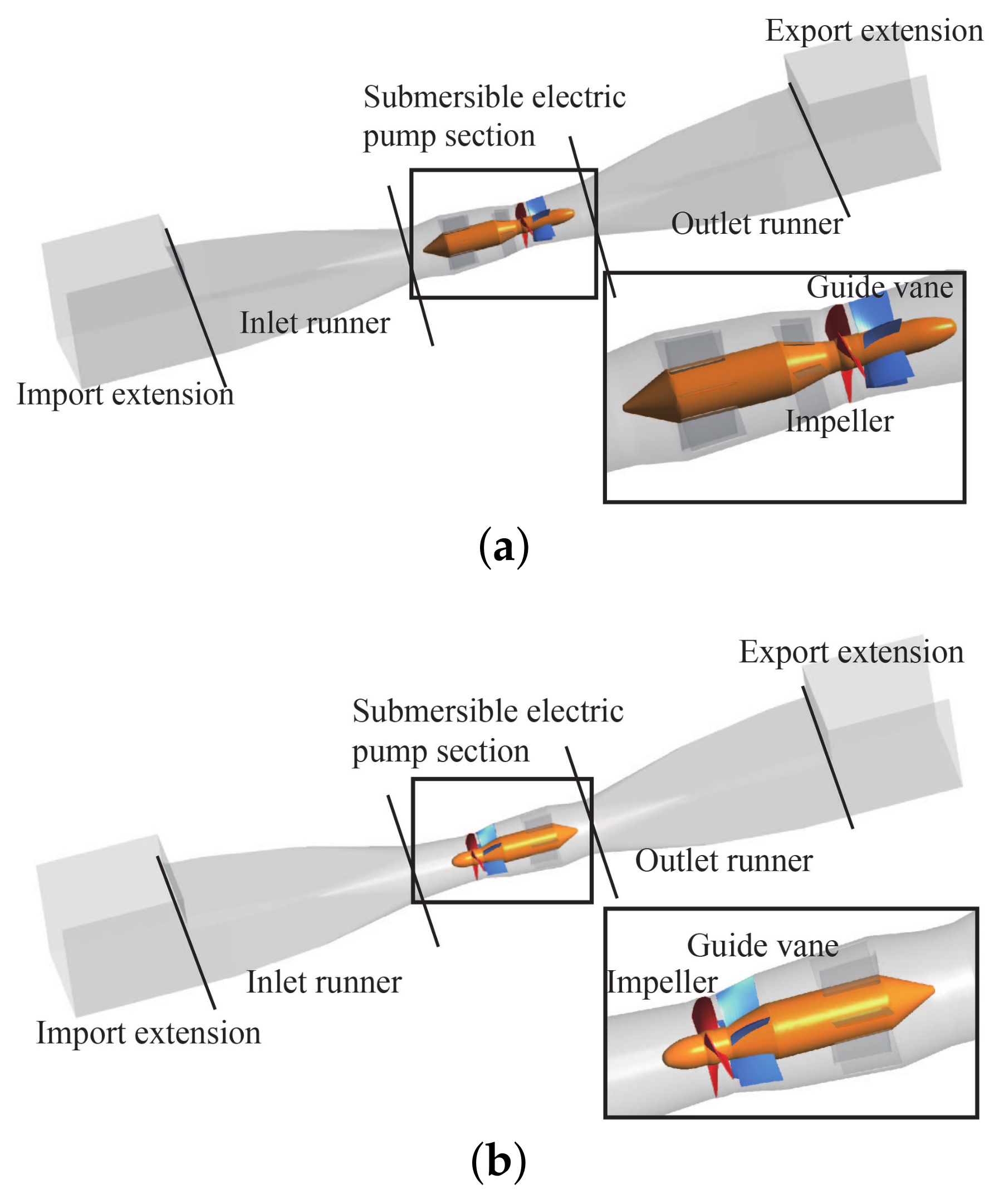
Taking a large-scale submersible tubular pumping station as the object of study, the designed head was 2.84 m and the maximum head was 3.81 m. The diameter and speed of the impeller of the prototype pump were 2400 mm and 169 r/min, respectively. The water pump impeller was selected from the GL-2008-03 hydraulic model with three blades. This hydraulic model is a major project of the National Science and Technology Support Plan of the “Eleventh Five-Year Plan”, for the research and application of several key technologies for the South-to-North Water Diversion Project. The impeller diameter of the model pump was 300 mm, which was scaled according to the principle of equal nD value, and the model speed was 1352 r/min. In the case of the same main control size, the submersible tubular pump device bulb front and motor rear solutions were optimized based on CFD, and the three-dimensional structure of the model was finally obtained, as shown in Figure 1. In the picture, the dimensions of the inlet flow passage and the outlet flow passage are exactly the same. The rear-mounted scheme replaces the five supports at the front of the impeller inlet of the front-mounted scheme with diffusion guide vanes. At the same time, in order to fully develop the flow, an extension section was added at the inlet and outlet in the model.
The vortex energy at the impeller outlet of the axial flow pump accounts for 6–20% of the axial flow pump, and a rear guide vane must be used to effectively convert most of the vortex energy at the impeller outlet into pressure energy [19,20]. The front-mounted solution used conventional guide vanes, designed according to the GL-2008-03 impeller. The number of guide vanes was 5, and the impeller plus guide vane model code was ZM25. This model has excellent hydraulic performance, a nominal specific speed of 1200, and a pump section with a maximum efficiency of 85.2%. The rear-mounted solution adopted diffuser guide vanes designed according to the size of the motor and used the plane cascade method to design the guide vanes, where the number of guide vanes was also 5. The design was carried out after the CFD analysis of the impeller. The three-dimensional flow field of the impeller outlet at the characteristic operating point was taken as the inlet flow field of the guide vane design, and the water flow direction of the guide vane outlet was set to the axial direction.
3. Numerical Simulation and Experimental Setup
3.1. Turbulence Model and Boundary Conditions
The numerical calculation was carried out based on Ansys CFX. The control equation was the incompressible Reynolds time-averaged equation, and the turbulence model was the SST model. The SST model was modified by the standard and models. The model takes into account the near-wall performance of the model and the far-field accuracy of the model, and it can accurately predict the internal flow characteristics of the pump [21]. The transport equations for the turbulent kinetic energy k and the specific dissipation rate in the SST model can be expressed as follows:
The turbulent viscosity of the SST model is defined as:
where u represents the speed (m/s); is the density (kg/m); is the turbulence generation rate; , , , , , and are model constants; S is a module of the strain rate tensor; and are mixed functions. The SST model mixing function construction and constant value can be found in reference [22].
The inlet adopted the flow inlet condition, while the outlet adopted the pressure outlet condition. The entire calculation domain was divided into a rotating domain and a static domain. The impeller formed the rotating domain, and the rest was the static domain. The “Stage” interface was used to process the flow parameter transfer when the impeller inlet and outlet were coupled with dynamic and static conditions. For the solid wall surfaces of the submersible tubular pump device (e.g., the inlet and outlet channels, the hub of the impeller, the casing, and the guide vane body), non-slip conditions were applied. At the same time, the wall function was used in the near-wall area, in order to adapt to the turbulence model.
3.2. Computational Grid
The computational domain adopted a block grid division strategy, in which the impeller and guide vane area were divided by a hexahedral structured grid using Turbogrid. The bulb section had a complex structure, ICEM was used for unstructured meshing, and the rest of the calculation area was a hexahedral structured meshing constructed by ICEM. The grid parameter is a dimensionless quantity describing the distance from the first layer of the grid to the wall. In this study, the values of the main flow components, such as the impeller, were all within 30, which basically met the requirements for the application of the SST turbulence model for the quality of the near-wall grid.
3.3. Grid Independence Test
At a speed of 1352 r/min and flow rate of 0.295 m/s, the full flow channel calculation was performed, and the grid independence test was performed using the calculation result of the head as an index. Maintaining the same topological structure, we used the global maximum grid size to control the grid density of each computational domain and, at the same time, we specially refined the local grid of each computational domain to ensure the quality of the grid. We used the grid convergence method (GCI, Grid Convergence Index) recommended by Roache and Patrick [23], based on Richardson’s extrapolation theory; the results are shown in Table 1. Three sets of different-sized computational grids were determined, and the number of grids varied from large to small. The GCI value of the fine-grid scheme was based on the medium-grid scheme, and the GCI value of the medium-grid scheme was based on the coarse-grid scheme. The numerical uncertainty of the medium-grid scheme and the fine-grid scheme for the front- and rear-mounted schemes was less than 3%, and the discrete error was small. Considering the calculation time and accuracy, the medium-grid scheme was selected as the final computational grid. The main component grid is shown in Figure 2.
3.4. Model Test
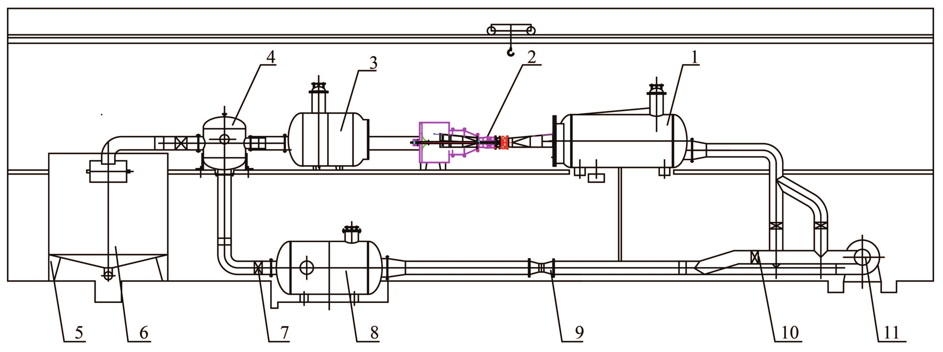
A model test was carried out on a high-precision hydraulic machinery test bench. The test bench passed the appraisal organized by the Jiangsu Science and Technology Department in September 2001. The efficiency test system has a comprehensive error of ±0.39% and passed the national metrology certification. The test bench is a vertical closed loop system, as shown in Figure 3. The total length of the hydraulic closed circulation system of this test bench is 60.0 m, and the pipe diameter is 0.5 m. Only the 10 times straight pipe before and after the electromagnetic flowmeter is installed as a 0.4 m pipe, and the water volume of the entire system is 50 m.
The main instrumentation of the test measurement system is shown in Table 2. The primary sensors, differential pressure transmitters, and speed and torque sensors used for testing flow, head and torque, speed, and so on, were all calibrated by a nationally recognized metrology calibration department and were within the validity period. The system uncertainty of the test bench pump unit performance efficiency test is the square sum root of each individual system uncertainty, with a system uncertainty of ±0.24%.
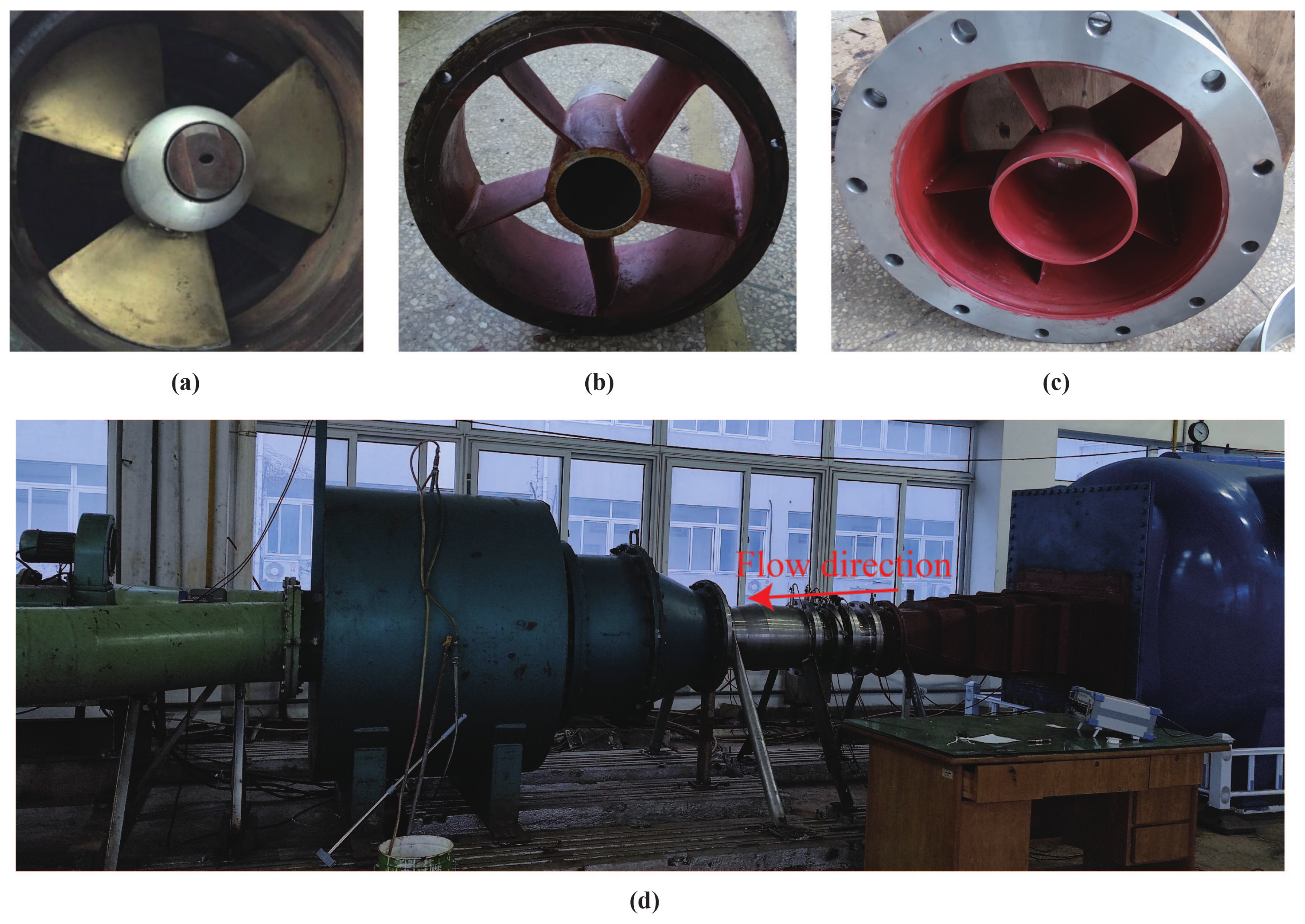
The same axial impeller was used in the front- and rear-mounted schemes. Figure 4a shows the axial flow pump impeller used, which was made of brass material. The number of blades was three, and the impeller chamber adopted a split structure to facilitate disassembly and blade angle adjustment. Conventional guide vanes for the front-mounted schemes and diffusion guide vanes for the rear-mounted schemes are shown in Figure 4b,c. They were made of cast steel and the number of guide vanes was 5. The inlet and outlet channels were welded by steel plates, and the motor section was precisely processed, according to the CAD dimensions. The model pump was checked during installation. The axial runout of the positioning surface of the guide vane and impeller was 0.10 mm, the radial runout of the outer surface of the hub was 0.08 mm, and the tip clearance was controlled within 0.15 mm. The rear-mounted model pump device is shown in Figure 4d. The outlet flow channel is placed inside the water tank, and the motor, torque meter, and so on, were placed on the outside of the water tank. The impeller was driven through the long axis of the water tank. After many improvements, installation, and debugging, the operation was basically stable, in line with the actual pump conditions. As the sizes of the inlet flow passage and the outlet flow passage were exactly the same, it can become a front-mounted submersible tubular pump device, by replacing the impeller steering and corresponding guide vanes.
4. Results and Discussion
4.1. Comparison of External Characteristics
The test was carried out according to the “Hydraulic turbines, storage pumps and pump-turbines-Model acceptance tests” (IEC 60193-2019) standard. The energy characteristics of the front- and rear-mounted solutions, with a speed of 1352 r/min, were obtained; the results are shown in Figure 5. The test results show that the head of the rear-mounted scheme was slightly higher than that of the front-mounted scheme under different flow conditions, and the efficiency of the rear-mounted scheme was generally higher than that of the front-mounted scheme, especially under high-flow conditions. The maximum efficiency point flow of the front- and rear-mounted solutions were both around 295 L/s, the maximum efficiency of the rear-mounted solution was about 78.4%, the maximum efficiency of the front-mounted solution was about 77.5%, and the difference in efficiency was about 1%. This is consistent with the results in the literature [24], which indicate that the efficiency of the rear-mounted submersible tubular pump device is higher than that of the front-mounted scheme under the premise of a good guide vane design.
4.2. Analysis of Hydraulic Loss and Flow Field
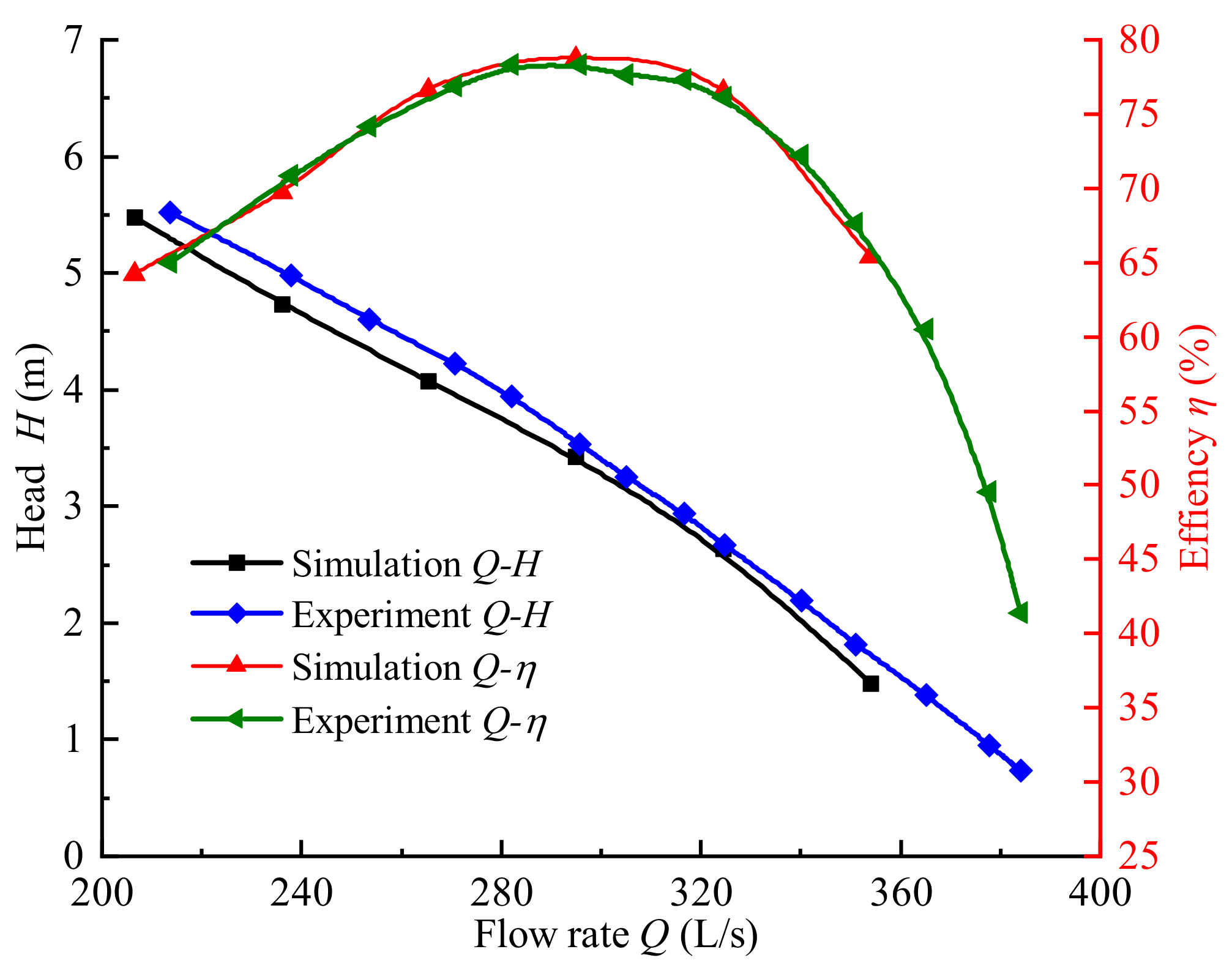
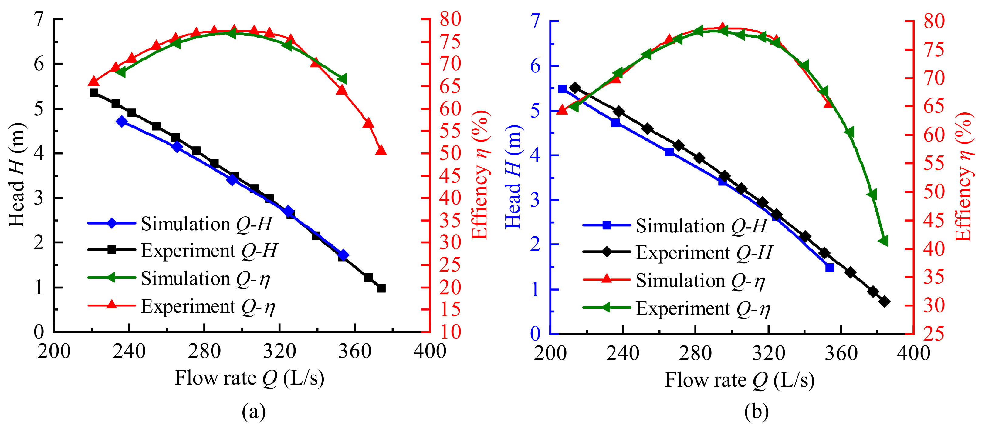
The difference in external characteristics is often caused by the internal flow field, and the performance difference of the two schemes is further analyzed in combination with numerical simulation. Figure 6 shows a comparison between the numerical calculation results and the experiment of the two schemes. The figure shows that, in the whole calculation range, the law of the external characteristic relationship curve obtained from the numerical simulation result and the experimental result was basically the same, and there was a certain deviation in the head under the small flow condition. This was mainly because the small flow conditions were close to the saddle area, and the internal flow was more complicated; however, the overall results were in good agreement and, thus, the results of the numerical simulation can be considered to be highly reliable.
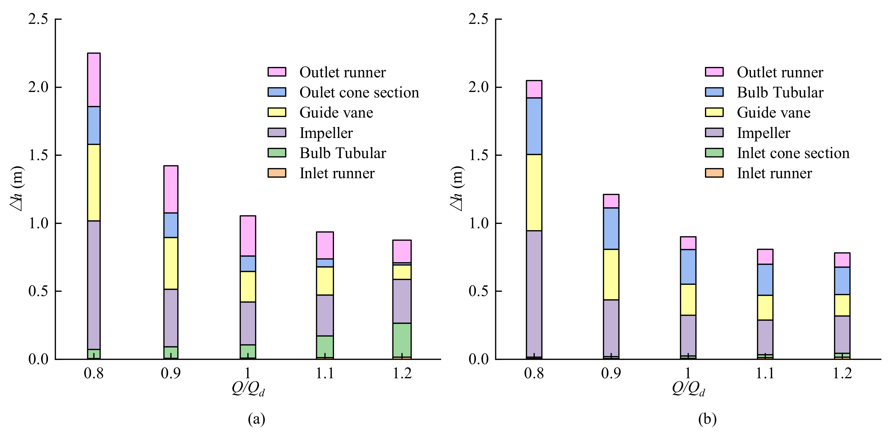
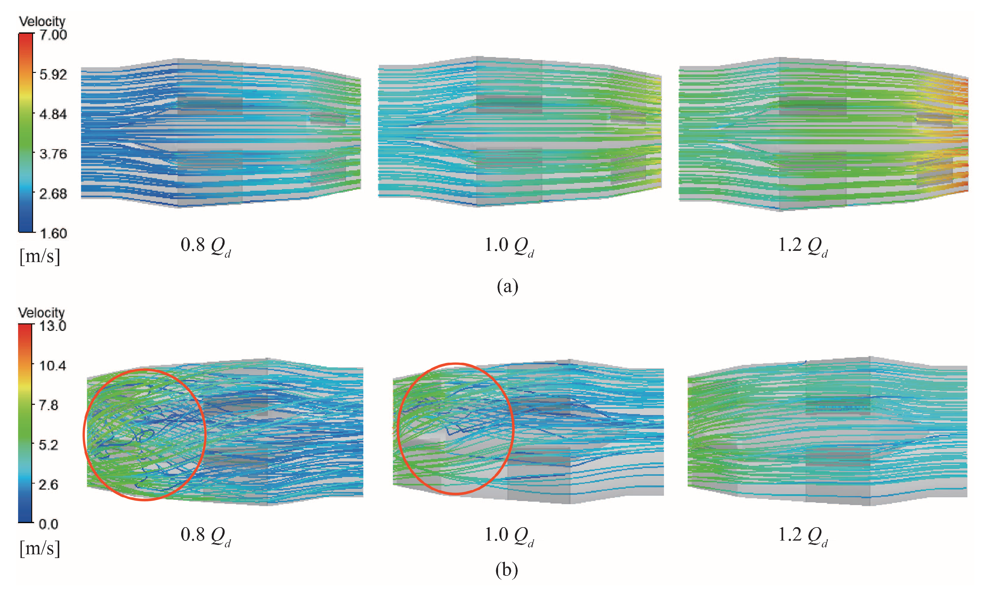
Under different flow conditions, the hydraulic loss of the main flow-passing parts of the front-mounted and rear-mounted schemes is shown in Figure 7, is the flow rate corresponding to the highest efficiency point, equal to 295 L/s. The hydraulic loss of the fixed part was calculated using the total pressure difference value, and the rotation input power of the rotating part was calculated by subtracting the total pressure rise of the fluid. The loss of the inlet channel for the two schemes increased with the increase in the flow, but the hydraulic loss was very small, and the efficiency of the pump device mainly depended on other flow-through components. The hydraulic loss of the bulb section of the front-mounted scheme was significantly smaller than that of the rear-mounted scheme. Similar to the water inlet channel, the hydraulic loss gradually increased with the increase of the flow rate, which basically satisfied the linear function relationship with the second power of the flow velocity. Under large flow conditions, the hydraulic loss accounted for an important part of the pump device loss, while the rear-mounted bulb loss did not satisfy the linear relationship of the flow quadratic. Figure 8 shows the internal three-dimensional streamline of the bulb segment. Under different flow conditions, the front-mounted solution bulb was located on the water inlet side, its internal flow line was straight, and the internal flow state was good. In the case of small flow and design flow, the rear-mounted solution of the bulb was affected by the guide vane outlet ring. Before the bulb body is supported, the water flows into an obvious vortex and, thus, there was obvious de-flow near the hub, while the axial velocity of the large flow was relatively high. The flow was dominated by the axial speed, and the water flow was relatively straight. After rectification of the support and contraction of the bulb section tail, the streamline became smooth and straight when it reached the outlet. The hydraulic loss of the section increased but, at the same time, it also plays the role of rectification and recycling, such that the outlet flow channel had better inflow conditions.
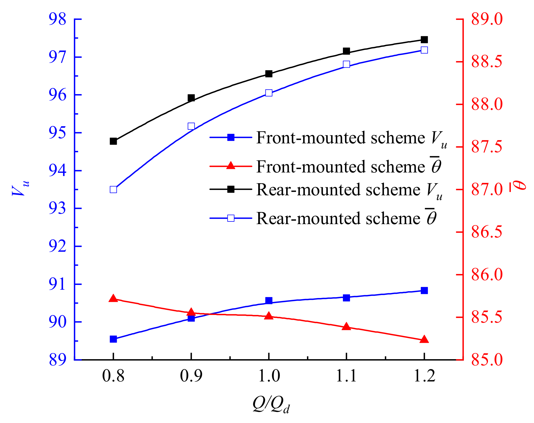
From the perspective of impeller hydraulic loss, the hydraulic loss of the impeller of the front-mounted scheme is greater than that of the rear-mounted scheme, mainly because the bulb was arranged on the water inlet side, which made the inflow state of the impeller worse and reduced the hydraulic efficiency of the impeller. The non-dimensional parameters of axial velocity distribution uniformity and the weighted average angle were used to quantitatively evaluate the inflow state of the impeller inlet [25,26], defined as follows:
where n is the number of units in the numerical calculation section, is the average axial velocity of the section (m/s), is the axial velocity of each calculation unit at the outlet section of the flow channel (m/s), is the area of each unit on the section (m), A is the area of the outlet section (m), and is the tangential velocity of each grid cell in the inlet section (m/s). The formula uses the mass flow average to maximize the calculation error of the wall caused by the grid. In an ideal state, the impeller inlet has uniform and vertical inflow. Therefore, the higher is the uniformity of the velocity distribution and the closer to is the weighted average angle, the better is the inflow state. The calculation results of the impeller inlet section under different working conditions are shown in Figure 9. The axial velocity distribution uniformity and weighted average angle of the impeller inlet section under the rear-mounted scheme were obviously better than those under the front-mounted scheme. In the calculation conditions, the maximum difference in the flow velocity distribution uniformity was about 6.63%, the minimum difference was about 5.23%, the maximum difference of the weighted average angle was about , and the minimum difference was more than . As the flow rate increased, the axial velocity became dominant, and the flow velocity distribution uniformity and weighted average angle of the impeller inlet of the rear-mounted scheme gradually increased. In the front-mounted scheme, the bulb body in front of the impeller inlet shrank rapidly, the bulb body support had an obstructive effect on the water flow, and the weighted average angle decreased with an increase in the flow rate, showing different change trends. From the perspective of hydraulic loss, the diffuser guide vane adopted by the rear-mounted scheme was not much different from the guide vane of the conventional axial flow pump adopted in the front-mounted scheme. The impeller outlet has a large vortex energy. After the rectification of the guide vane, part of it is converted into the loss of the guide vane, while the other part is converted to the pressure of the water flow. The kinetic energy recovery coefficient, , can be used to measure the circulation recovery capacity of the guide vane [27]. The calculation formula is:
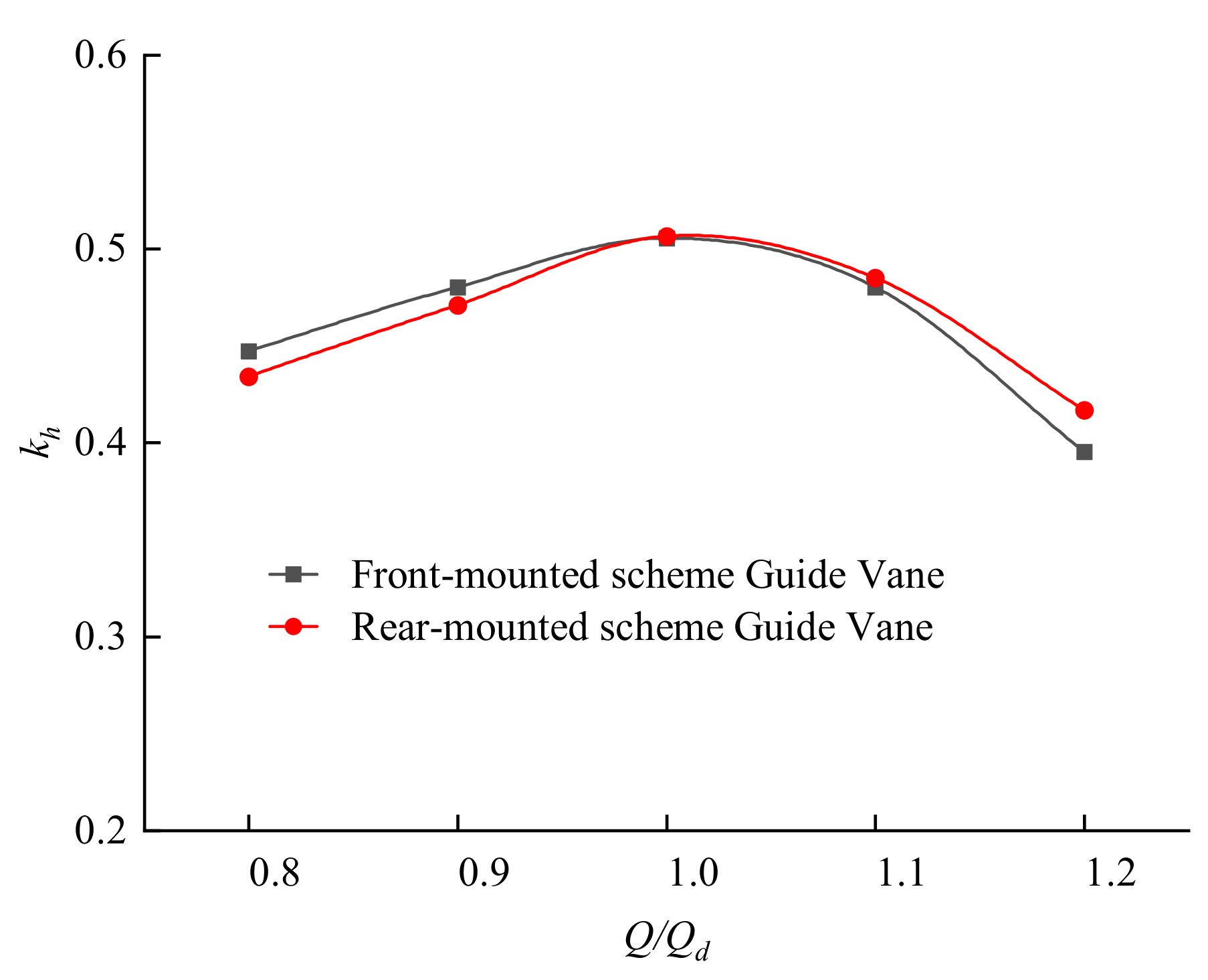
where and are the average velocity of the inlet and outlet, respectively (m/s); is the hydraulic loss of the guide vane section (m); g is the acceleration due to gravity (m/s). Figure 10 shows the kinetic energy recovery coefficient of the guide vane outlet under different flow conditions. It can be found that, under the design conditions, the kinetic energy recovery coefficients of the diffuser vane and the conventional axial flow pump vane were basically the same. Under the small flow condition, the conventional vane was higher than the diffuser vane, while the diffuser vane was higher in the large flow condition. This is related to the design of the guide vane and does not have a universal law, but it can also demonstrate that the hydraulic performance of the diffuser guide vane is equivalent to that of an excellent conventional guide vane when the design is good.
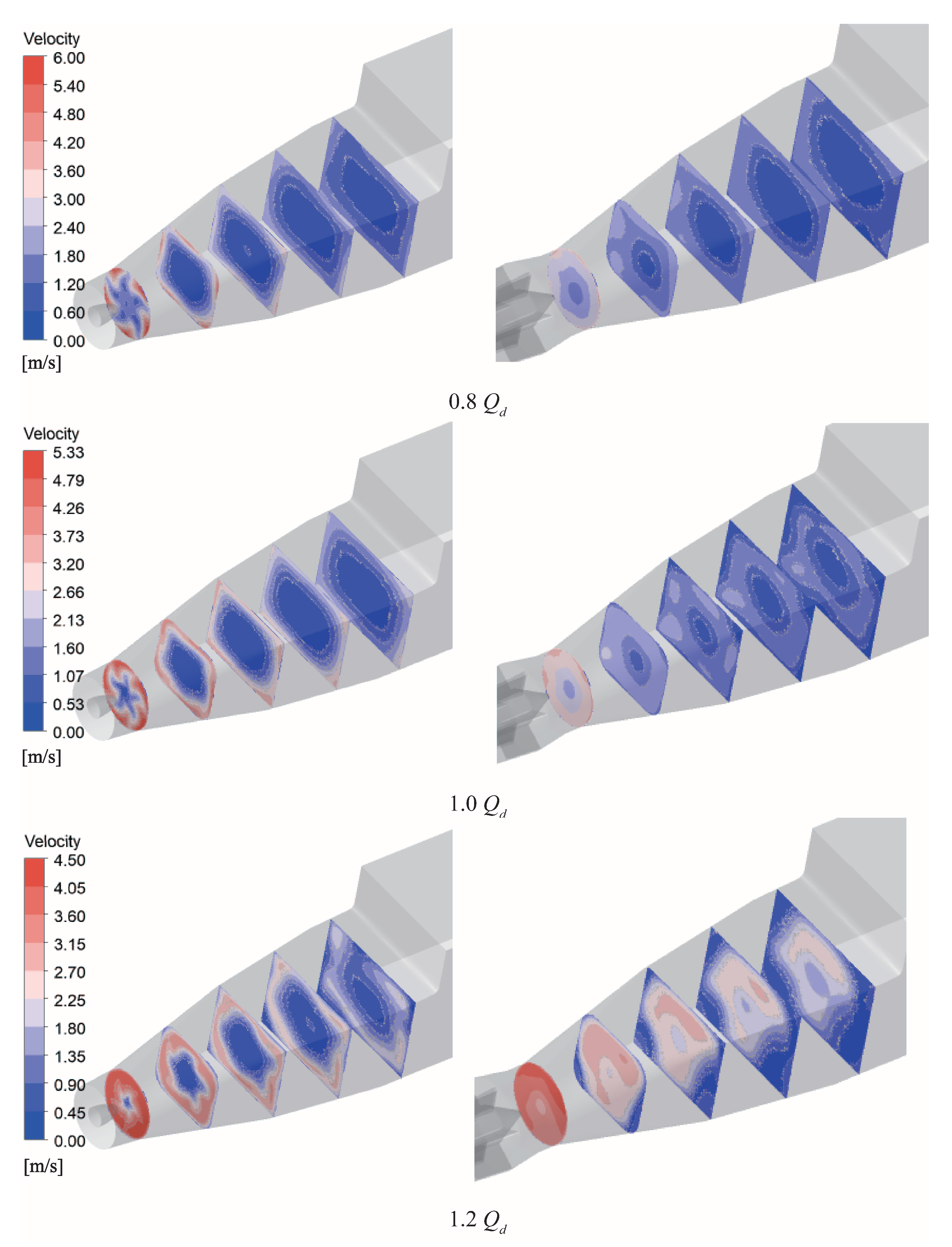
The hydraulic loss of the outlet channel under the rear-mounted scheme was significantly less than that under the front-mounted scheme, which is related to the flow field at the inlet of the outlet channel. Figure 11 shows the velocity distribution inside the outlet channel under characteristic conditions. In the front-mounted scheme, the outlet flow channel was affected by the circulation of the guide vane outlet. There was an obvious low-velocity zone inside the flow channel, and the diffusion of the outlet flow channel caused a large drain inside. The water flow was affected by the centrifugal force and squeezed to the surroundings to produce an obvious adhesion effect, which increased the loss of the flow channel. In the rear-mounted scheme, the water flow was rectified by the guide vanes and the bulb section, while the volume at the inlet of the outlet flow channel was small. This made the outlet flow area under the rear-mounted scheme significantly smaller than that under the front-mounted scheme, which explains the low hydraulic loss of the outlet channel under the rear-mounted scheme.
4.3. Entropy Generation Analysis
The principle of entropy increase is one of the expressions of the second law of thermodynamics; that is, the micro-increase of entropy in an irreversible process is always greater than zero. Entropy generation refers to the inevitable existence of effects caused by irreversibility in a process, which converts the lost mechanical energy into internal energy, resulting in energy dissipation. In recent years, entropy generation theory has been widely used in the analysis of internal flow losses and hydraulic machinery stability [28]. For turbulent flows, the entropy generation rate can be divided into two parts: the first is caused by the average velocity, called the direct dissipation term, while the second is caused by the pulsating velocity, called the turbulent dissipation term, defined as:
where is the total entropy production rate (W/(m·K)), is the entropy production rate caused by the average speed (W/(m·K)), and is the entropy production rate caused by the pulsating speed (W/(m·K)). The entropy production caused by the average speed is
and the entropy production caused by the pulsating speed is
where , , and are the components of the average velocity in the x, y, and z direction (m/s), respectively; , , and are the components of the pulsating velocity in the x, y, and z directions (m/s), respectively; is the hydrodynamic viscosity (Pa/s); is the effective viscosity of the fluid (Pa/s); T is the temperature (K). However, the pulsation component cannot be calculated directly in the Reynolds time-average equation. This paper adopts the SST model, and the pulsation entropy production can be approximated by:
where the empirical coefficient is 0.09, f is the characteristic frequency of turbulent pulsation (s), k is the turbulent kinetic energy (m/s), and is the density. Herwig and Kock [29,30] found that there are wall effects in the above two parts of the entropy generation rate. If the entropy generation rate formula given above is directly used near the wall surface, it will cause large errors. Zhang [31] gave the calculation method for wall friction loss, and the calculation formula of the local wall entropy production rate per unit area is as follows:
where is the wall shear stress (Pa) and is the velocity at the center of the first layer near the wall (m/s). The direct dissipation entropy production (W/k), turbulent dissipation entropy production (W/k), and wall surface entropy production (W/k) can be obtained for the above-mentioned parts of the entropy production rate in the integral region.
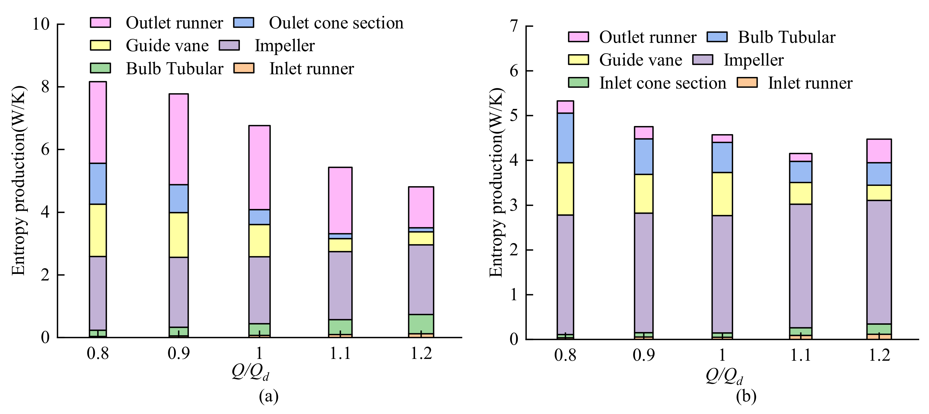
Figure 12 shows the entropy production distribution of each flow component under different working conditions, where its entropy production change trend is basically the same as the hydraulic loss, indicating that the entropy generation theory can well-reflect the internal flow loss. In order to visually display the specific location of the hydraulic loss, the entropy generation rate of the longitudinal section of the pump device under the two schemes is shown in Figure 13. Under the same flow conditions, the high value area of entropy production rate under the rear-mounted scheme was smaller than that under the front-mounted scheme. The high-value areas, in terms of the entropy production rate, under the front-mounted scheme were mainly in the impeller, the guide vane, and the outlet flow channel, and there was a large area of high entropy production in the outer wall of the outlet flow channel. This was caused by the internal flow out of the water outlet channel, as shown in Figure 11. Affected by the annular volume of the guide vane outlet, the water flow was squeezed around to increase the entropy production rate of the outer wall of the water outlet channel, thus reducing the efficiency of the device. In addition to the impeller and guide vanes in the rear-mounted scheme, a high entropy production rate was observed in the bulb section, and there was also higher entropy production near the bulb support. Therefore, optimizing the shape of the bulb section and the bulb support, reducing the hydraulic loss of the bulb section and the bulb support, and, at the same time, exerting its rectification effect can lead to optimization of the rear-mounted submersible tubular pump device.
5. Conclusions
In this study, a method combining model testing and numerical simulation was used to compare the hydraulic performances of front- and rear-mounted bulb submersible tubular pumps. The following conclusions were reached:
- In the case of a well-designed diffusion guide vane, the efficiency under the rear-mounted scheme was higher than that under the front-mounted scheme. The maximum efficiency under the rear-mounted solution was about 78.4%, and the maximum efficiency under the front-mounted solution was about 77.5%.
- Although the front-mounted scheme can reduce the hydraulic loss of the bulb section, it may worsen the flow state of the impeller inlet. The rear of the bulb has better water inlet conditions and the impeller is more efficient. The bulb body is located on the water outlet side, which plays the role of recovering the guide vane outlet circulation and rectification, reducing the hydraulic loss of the water outlet channel.
- The entropy generation under the front-mounted scheme was mainly on the outer wall of the outlet flow channel, as the drained water inside the outlet flow channel was squeezed around, causing large-scale entropy production in the outer wall area. The high value area of the entropy production rate under the rear-mounted solution was in the bulb section, and the bulb support also caused higher entropy production. For the bulb rear-mounted submersible tubular pump device, how to reduce the hydraulic loss of the bulb segment and the bulb support while, at the same time, exerting its rectification function will be key to optimizing its design in the future.
Author Contributions
Data curation, Z.S.; Formal analysis, F.T.; Writing—original draft, Z.S.; Writing—review and editing, J.Y. All authors have read and agreed to the published version of the manuscript.
Funding
This work was supported by the National Natural Science Foundation of China (grant number 51376155); the Natural Science Foundation of Jiangsu Province of China (grant number BK20190914); China Postdoctoral Science Foundation Project (2019M661946); the Natural Science Foundation of Jiangsu Higher Education Institutions of China (grant number 19KJB570002); the National Science Foundation of Yangzhou of China(grant number YZ2018103); the Priority Academic Program Development of Jiangsu Higher Education Institutions (grant number PAPD).
Institutional Review Board Statement
Not applicable.
Informed Consent Statement
Not applicable.
Data Availability Statement
Not applicable.
Acknowledgments
This project funded by the Priority Academic Program Development (PAPD) of Jiangsu Higher Education Institutions Support for construction. Assembly of the facility was also provided by the Hydrodynamic Engineering Laboratory of Jiangsu Province.
Conflicts of Interest
The authors declare no conflict of interest.
References
- Zhang, R. Study on Application of Tubular Pumps in the Project of South to North Water Transfer Project. Drain. Irrig. Mach. 2004, 5, 1–6. [Google Scholar]
- Rentian, Z.; Shan, H.; Bu, G.; Zhou, W.; Zhu, H.; Yao, L. Structural features of bulb tubular pumps in first phase of South-to-North Water Diversion Eastern Route Project in China. J. Drain. Irrig. Mach. Eng. 2016, 34, 767–775. [Google Scholar]
- Zhang, R. Performance analysis of bulb tubular pumps in the first phase of South-to-North Water Diversion Eastern Route Project in China. J. Drain. Irrig. Mach. Eng. 2017, 35, 32–41. [Google Scholar]
- Zhang, D.; Dai, Z.; Liao, R.; Cheng, M.; Xia, J. Characteristic experiment on flow pump set model and energy-saving. Energy Res. Util. 2003, 3, 22–24. [Google Scholar]
- Yang, H.; Huang, L.; Xia, J.; Wang, J. The Choice of Umbrella-Gear Transmission Routing Through Pump Unit’s Structure Types in Luyang Pumping Station Project of the Channel Which Leading Huaihe River Into Sea. Drain. Irrig. Mach. 2004, 22, 9–13. [Google Scholar]
- Lu, L.-G.; Huang, J.-J.; Chen, J.; Chen, A.P.; Wang, X.-M.; Zou, J.-G. Numerical study of 3D flow in a bulb Tubular pump system. Drain. Irrig. Mach. 2007, 25, 15–20. [Google Scholar]
- Lu, L.G.; Chen, J.; Liang, J.D.; Leng, Y. Optimal hydraulic design of bulb tubular pump system. J. Hydraul. Eng. 2008, 39, 355–360. [Google Scholar]
- Lu, W.; Wang, D.; Shi, W.; Liu, J.; Xu, L. Comparison of hydraulic performance between submersible tubular pump device with motor front and rear arrangements. J. Drain. Irrig. Mach. Eng. 2020, 38, 325–331. [Google Scholar]
- Tang, F.; Liu, C.; Zhou, J.; Yuan, J.; Li, C. Experimental Research on Scale Model of Low Head Tubular Axial-Flow Pumps Installation. Pump Technol. 2004, 4, 28–31. [Google Scholar]
- Tang, F.; Liu, C.; Xie, W.; Yuan, J.; Zhou, J.; Li, C. Experimental Studies on Hydraulic Models for a Reversible, Tubular, and Submersible Axial-flow Pump Installation. Trans. Chin. Soc. Agric. Mach. 2004, 35, 74–77. [Google Scholar]
- Wu, C.; Jin, Y.; Wang, D.; Yang, H.; Yang, F.; Liu, C. Study and application of large bidirectional submersible tubular pump system. J. Hydroelectr. Eng. 2012, 31, 265–270, 293. [Google Scholar]
- Xu, H. Tubular Pumping Station; China Water Conservancy and Hydropower Press: Beijing, China, 2008. [Google Scholar]
- Yang, F.; Jin, Y.; Liu, C.; Tang, F.; Cheng, L.; Yang, H. Numerical analysis and performance test on diving tubular pumping system with symmetric aerofoil blade. Trans. Chin. Soc. Agric. Eng. 2012, 28, 60–67. [Google Scholar]
- Dai, J.; Dai, Q.; Wang, H. Effect of Diffuser Blade Position on Hydraulic Performance of Bulb Tubular Pump. Water Resour. Power 2017, 35, 168–171. [Google Scholar]
- Jin, Y.; Liu, C.; Tang, F. 3D Numerical Simulation of Turbulent Flow in Postpositional Bulb Tubular Pump. J. Mech. Eng. 2010, 46, 167–174. [Google Scholar] [CrossRef]
- Jin, Y.; Liu, C.; Tang, F.; Zhou, J. Influence of Supporting Shape on the Hydraulic Performance of Bulb Tubular Pumps. Transac. Chin. Soc. Agric. Mach. 2009, 40, 78–82. [Google Scholar]
- Xia, C.; Cheng, L.; Jiang, H.; Xin, J. Hydraulic performance analysis and optimization on flow passage components of diving tubular pumping system. Trans. Chin. Soc. Agric. Eng. 2018, 34, 45–51. [Google Scholar]
- Shi, W.; Zhang, D.; Guan, X.; Cao, W. Optimization and experimental investigation on post bulb type tubular pump device model. J. Hydraul. Eng. 2010, 41, 1248–1253. [Google Scholar]
- Tang, F.; Shi, L.; Lei, C.; Yang, H.; Yang, F. Multidisciplinary Design Optimization of Axial-flow Pump Blades. Trans. Chin. Soc. Agric. Mach. 2014, 45, 96–100. [Google Scholar]
- Tang, F. Design of Waterjet Axial Flow Pump and Numerical Analysis of Turbulent Flow. Ph.D. Thesis, Shanghai Jiao Tong University, Shanghai, China, 2007. [Google Scholar]
- Langtry, R.B.; Menter, F.R. Correlation-Based Transition Modeling for Unstructured Parallelized Computational Fluid Dynamics Codes. AIAA J. 2009, 47, 2894–2906. [Google Scholar] [CrossRef]
- Menter, F.R.; Kuntz, M.; Langtry, R. Ten years of industrial experience with the SST turbulence model. Heat Mass Transf. 2003, 4, 625–632. [Google Scholar]
- Roache, P.J. Conservatism of the Grid Convergence Index in Finite Volume Computations on Steady-State Fluid Flow and Heat Transfer. J. Fluids Eng. 2003, 125, 731–732. [Google Scholar] [CrossRef]
- Jin, Y. Research on Numerical Simulation and Three-dimensional LDV Measurement of Tubular Pump Internal Flow. Ph.D. Thesis, Yangzhou University, Yangzhou, China, 2010. [Google Scholar]
- Liu, C. Water Pumps and Water Pumping Stations; China Water Conservancy and Hydropower Press: Beijing, China, 2009. [Google Scholar]
- Zhu, H.; Yuan, S.; Liu, H.; Shi, W. Numerical simulation of three-dimensional turbulent flow in volute outlet channel of large pumping station. Trans. Chin. Soc. Agric. Mach. 2007, 38, 49–53. [Google Scholar]
- Wang, Z.; Peng, G.; Zhou, L.; Hu, D. Hydraulic performance of a large slanted axial-flow pump. Eng. Comput. 2010, 27, 243–256. [Google Scholar] [CrossRef]
- Bejan, A. Entropy Generation Minimization: The Method of Thermodynamic Optimization of Finite-Size Systems and Finite-Time Processes. J. Appl. Phys. 1996, 79, 1191–1218. [Google Scholar] [CrossRef] [Green Version]
- Herwig, H.; Kock, F. Direct and indirect methods of calculating entropy generation rates in turbulent convective heat transfer problems. Heat Mass Transf. 2007, 43, 207–215. [Google Scholar] [CrossRef]
- Kock, F.; Herwig, H. Local entropy production in turbulent shear flows: A high-Reynolds number model with wall functions. Int. J. Heat Mass Transf. 2004, 47, 2205–2215. [Google Scholar] [CrossRef]
- Zhang, X.; Wang, Y.; Xu, X.; Wang, H. Energy Conversion Characteristic within Impeller of Low Specific Speed Centrifugal Pump. Trans. Chin. Soc. Agric. Mach. 2011, 42, 75–81. [Google Scholar]
Figure 1.
Three-dimensional model of submersible tubular pump device: (a) front-mounted scheme; (b) rear-mounted scheme.
Figure 1.
Three-dimensional model of submersible tubular pump device: (a) front-mounted scheme; (b) rear-mounted scheme.

Figure 2.
Grid diagram of submersible tubular pump installation: (a) Pump unit; (b) front-mounted scheme; (c) rear-mounted scheme.
Figure 2.
Grid diagram of submersible tubular pump installation: (a) Pump unit; (b) front-mounted scheme; (c) rear-mounted scheme.

Figure 3.
Schematic diagram of high-precision hydraulic machinery test bench: (1) Inlet tank; (2) Tested pump device and drive motor; (3) Pressure outlet tank; (4) Bifurcated water tank; (5) Weighing sensor; (6) In-situ calibration device; (7) Adjusting gate valve; (8) Stabilized rectifier cylinder; (9) Electromagnetic flowmeter; (10) Control gate valve; (11) Auxiliary pump unit.

Figure 4.
Submersible tubular pump device: (a) GL-2008-03 impeller; (b) conventional guide vane; (c) diffuser guide vane; (d) bulb rear-mounted submersible tubular pump device.
Figure 4.
Submersible tubular pump device: (a) GL-2008-03 impeller; (b) conventional guide vane; (c) diffuser guide vane; (d) bulb rear-mounted submersible tubular pump device.

Figure 5.
Energy test results.

Figure 6.
Comparison between numerical simulation and experimental results: (a) front-mounted scheme; (b) rear-mounted scheme.
Figure 6.
Comparison between numerical simulation and experimental results: (a) front-mounted scheme; (b) rear-mounted scheme.

Figure 7.
Hydraulic loss analysis: (a) front-mounted scheme; (b) rear-mounted scheme.

Figure 8.
Three-dimensional flow lines in the bulb: (a) front-mounted scheme; (b) rear-mounted scheme.
Figure 8.
Three-dimensional flow lines in the bulb: (a) front-mounted scheme; (b) rear-mounted scheme.

Figure 9.
Velocity distribution of the impeller inlet section.

Figure 10.
Kinetic energy recovery coefficient of the guide vane.

Figure 11.
Internal velocity distribution of the outlet flow channel under different flow conditions: (left) front-mounted scheme; (right) rear-mounted scheme.
Figure 11.
Internal velocity distribution of the outlet flow channel under different flow conditions: (left) front-mounted scheme; (right) rear-mounted scheme.

Figure 12.
Entropy generation analysis: (a) front-mounted scheme; (b) rear-mounted scheme.

Figure 13.
Distribution of entropy production rate inside the pump device under different flow conditions: (a) 0.8 (b) 1.0 (c) 1.2 .
Figure 13.
Distribution of entropy production rate inside the pump device under different flow conditions: (a) 0.8 (b) 1.0 (c) 1.2 .


Table 1.
Comparison of calculation results of pump device head under different grid numbers.
| Scheme | Number of Grids (106) | Head (m) | GCI (%) | |
|---|---|---|---|---|
| Front-mounted scheme | Fine | 8.64 | 3.421 | 0.97 |
| Medium | 6.63 | 3.413 | 2.29 | |
| Coarse | 4.63 | 3.389 | ||
| Rear-mounted scheme | Fine | 8.53 | 3.431 | 1.23 |
| Medium | 6.53 | 3.423 | 1.54 | |
| Coarse | 4.54 | 3.409 |
Table 2.
Main equipment of test measurement system.
| Measuring Items | Instrument | Instrument Model | Measuring Range | Calibration Accuracy |
|---|---|---|---|---|
| Head | Differential pressure transmitter | EJA110A | 0–200 kPa | ±0.1% |
| Flow rate | Electromagnetic Flowmeter | E-mag | DN400 mm | ±0.2% |
| Torque and rotation speed | Speed and torque sensor | JC2C | 200 N·m | ±0.1% |
Publisher’s Note: MDPI stays neutral with regard to jurisdictional claims in published maps and institutional affiliations. |
© 2021 by the authors. Licensee MDPI, Basel, Switzerland. This article is an open access article distributed under the terms and conditions of the Creative Commons Attribution (CC BY) license (https://creativecommons.org/licenses/by/4.0/).
Share and Cite
MDPI and ACS Style
Sun, Z.; Yu, J.; Tang, F. The Influence of Bulb Position on Hydraulic Performance of Submersible Tubular Pump Device. J. Mar. Sci. Eng. 2021, 9, 831. https://doi.org/10.3390/jmse9080831
AMA Style
Sun Z, Yu J, Tang F. The Influence of Bulb Position on Hydraulic Performance of Submersible Tubular Pump Device. Journal of Marine Science and Engineering. 2021; 9(8):831. https://doi.org/10.3390/jmse9080831
Chicago/Turabian StyleSun, Zhuangzhuang, Jie Yu, and Fangping Tang. 2021. "The Influence of Bulb Position on Hydraulic Performance of Submersible Tubular Pump Device" Journal of Marine Science and Engineering 9, no. 8: 831. https://doi.org/10.3390/jmse9080831
Note that from the first issue of 2016, this journal uses article numbers instead of page numbers. See further details here.