1. Introduction
Recent studies on the fatigue of metals have shown that compressive residual stresses can improve the fatigue resistance [
1]. Nowadays, many different approaches that are based on the generation of compressive residual stresses are widely used in the industry. For example, cold expansion [
2], shot peening [
1], deep rolling [
3], low plasticity burnishing [
4], and laser surface heating [
5].
One of the most promising approaches to surface treatment is laser shock peening (LSP), which enables the creation of significant compressive residual stresses, up to a depth of several mm [
6]. The first study of this effect was carried out in the USSR in Lebedev Physical Institute in 1962 [
7]. It has been shown that mechanical pressure from the surface is 100 times higher than the pressure generated by the photons of the laser beam. This effect was studied in detail in [
8,
9,
10], but was not found to have industrial application in that time. The development of high-power solid-state lasers allows the proposal of an alternative way of using these technologies for generating deep residual stresses.
LSP Technologies Inc. and Metal Improvement Company (business unit of the Surface Technologies Division of Curtiss-Wright Corporation), who gained access to high energy solid state pulsed laser technology in the late 1980s, developed industrial processes of generating deep compressive residual stresses for metal structures in order to improve their crack resistance [
11].
Nowadays, a large number of research teams [
12,
13,
14,
15,
16,
17] actively study LSP, including the effect of LSP process parameters (focus size, pulse energy, laser power density, surface preparing procedure) on the value and depth of compressive residual stresses. From a mechanical point of view, laser shock peening induces change in the material structure in a short characteristic time. The formed defect structures have an increased level of stored energy, and its evolution can lead to anomalous dissipative behavior of the material during cyclic deformation.
Specimen heating during cyclic deformation induced by the movement and annihilation of defects is used in Risitano’s test as an express technique for the evaluation of the fatigue limit in metals [
18]. Nowadays, Risitano’s test and infrared thermography is actively used in the investigation of various mechanical and material science problems [
19,
20,
21,
22].
Previously, it has been shown that the initial structure of the material significantly affects the results of the Risitano’s test, and can lead to unexpected results. For example, the study of submicrocrystalline titanium, obtained by equal channel angular extrusion, has shown that a high level of structural defects leads to an intense energy dissipation at low stress amplitudes. Furthermore, the applied stress amplitude has a linear relationship with the temperature, up until the macroscopic crack initiation [
19,
23].
In this work, we investigate the effects of LSP on self-heating of ARMCO iron specimens during cyclic deformation. We follow Risitano’s experimental procedure for fatigue limit evaluation [
18,
19]. A comparative analysis of the samples before and after LSP has been conducted. This showed that surface treatment significantly affects fatigue and dissipative properties of the material. The structural analysis of the specimens before and after LSP processing revealed a change in structural deformation mechanisms, which led to a change in the dissipative properties of metals.
The microstructure of the specimens was examined using transmission (TEM) and scanning (SEM) electron microscopy, as well as electron backscattering diffraction (EBSD). Additionally, measurements of the microhardness were carried out on various distances of the surface. As a result, this showed that LSP significantly affects the evolution of the material structure during cyclic deformation, and can lead to a decrease in the fatigue life of the specimen. Dissipative properties of the specimen changed simultaneously with the fatigue properties.
2. Experimental Conditions
The experiments were carried out on ARMCO iron specimens in the initial state and after LSP. The chemical composition of ARMCO iron is presented in
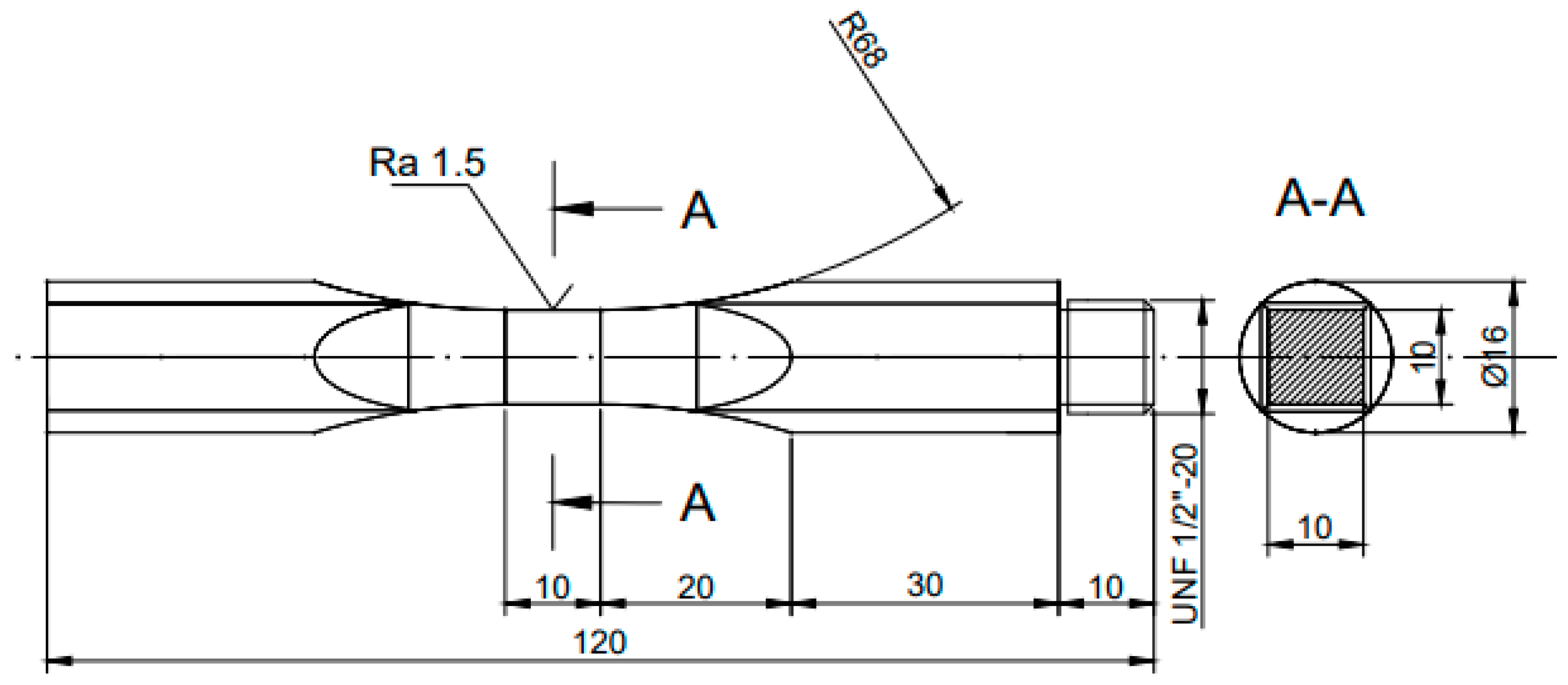
Table 1. The geometry of specimens for mechanical tests is presented in
Figure 1. Mechanical properties of ARMCO iron: elastic limit, 120 MPa; ultimate stress, 260 MPa [
24]. The fatigue properties of ARMCO iron is a well-studied problem, first investigated in 1963 [
24]. The effect of structure refinement on the fatigue properties of ARMCO iron has been studied in [
25,
26].
The self-heating test (Risitano test) allows one to link deformation-induced energy dissipation with the fatigue properties of the materials [
18]. The temperature increase in the representative volume of the material could be considered as a measure of energy that has dissipated, due to the structure evolution of metals. In order to investigate the effect that LSP has on energy dissipation and study the corresponding structure evolution, we designed the sample with a flat gauge surface. This specimen can be easily treated by LSP, and is appropriate for an infrared thermography study. The carried out self-heating test corresponds well to the Wöhler curve, determined in [
26]. To improve the quality of infrared measurement, the middle part of the sample has a cubical shape with a side of 10 mm. Two series of the specimens were prepared for the tests. The first one was in a virgin state. In the second series, each side of a cubical part was treated with LSP [
27]. The LSP process was carried out at Helmholtz-Zentrum Hereon using a Q-switched Nd:YAG laser (Quantel Laser, Les Ulis, France) operating at 5 J energy pulse, with a spot size of 2.5 mm (square spot) and a 50% overlap. The duration of the pulse was 20 ns (full width at half maximum).
In regards to the LSP process, the specimen surface is usually covered by a flowing water layer [
28]. Having passed through the water layer, the focused laser beam is absorbed by the material surface, which turns into plasma. At this stage, the plasma expansion occurs very rapidly, by absorbing the laser energy during the short laser pulse period. The transparent water layer traps the plasma, and, therefore, a higher pressure at the material surface is generated. The energy of the high-pressure plasma partially turns into mechanical shock waves, propagating through the material. If the shock wave pressure exceeds the dynamic yield strength of the material, plastic deformation occurs. The plastic deformation in the LSP treated area leads to the generation of compressive residual stresses, which are in balance with the tensile residual stresses in the surrounding areas. To avoid any thermal damage of the specimen surface, the target surface is generally covered a priori with an ablative layer. For this purpose, in the current study, the specimen surface was covered with a stainless steel foil, with the thickness of 0.1 mm.
The microstructure of the specimens was examined using transmission (TEM) and scanning (SEM) electron microscopy, as well as electron backscattering diffraction (EBSD).
TEM was done with a JEOL JEM 2100 microscope (JEOL Ltd., Tokyo, Japan); the analysed specimens were cut from the surface layer (300 μm thickness) and polished mechanically only from the inner side. Then, the specimens were prepared using twin-jet electro-polishing in a mixture of 90% acetic acid and 10% perchloric acid at 20 °C and 20 V.
SEM was carried out using FEI Quanta 600 FEG microscope (Thermo Fisher Scientific, Hillsboro, OR, USA). EBSD was conducted by FEI Nova NanoSEM 450 FEG SEM (ThermoFisher Scientific, Hillsboro, OR, USA) equipped with Hikari EBSD detector (EDAX Inc., Mahwah, NJ, USA) and TSL OIM™ system (version 6.0, EDAX Inc., Mahwah, NJ, USA) The step size of the EBSD scan was 1 μm. TSL OIM Analysis 6.2 was used to process EBSD data, and generate inverse pole figure (IPF) maps. On the presented maps, high angle boundaries (HABs) are indicated with black lines and low angle boundaries (LABs) are indicated with white lines. Points with a low confidence index (CI ≤ 0.1) were excluded from analysis and are depicted as black dots in the presented IPF maps. This software was used to generate inverse pole figures (IPF) and kernel average misorientation (KAM) maps. The results of the KAM showed a local grain misorientation, and can therefore be used to identify regions of high local strain. Specimens for SEM and EBSD were cut from a transversal section near the surface, and prepared by careful mechanical polishing.
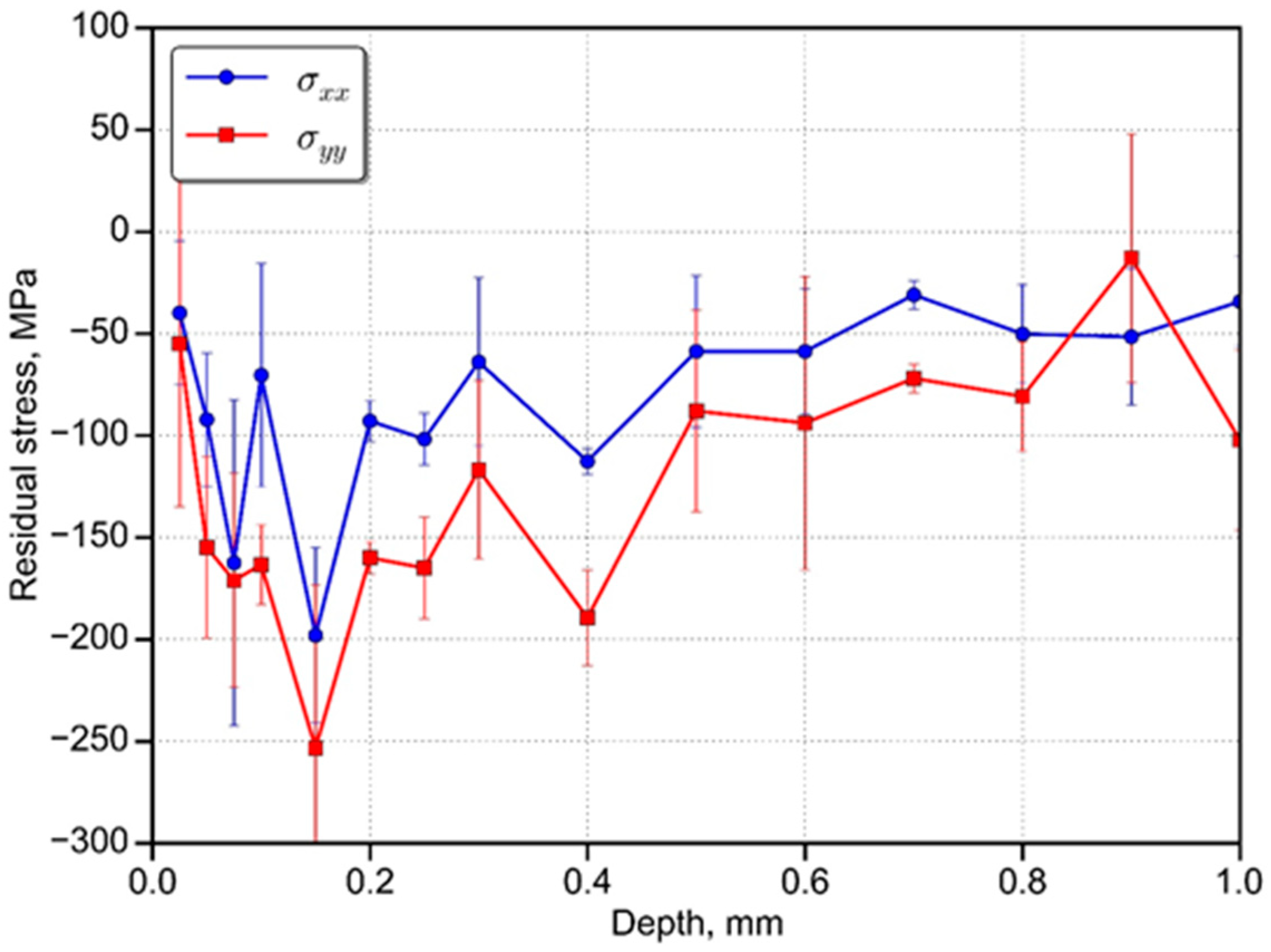
To determine the depth-resolved residual stresses (
Figure 2), the incremental hole drilling equipment “Prism” was used. “Prism” is equipped with an optical electronic speckle pattern interferometer (ESPI) system that provides high-quality full-field data for accurate residual stress determination. This technique has been described in detail in [
29]. The maximum compressive stress is 250 MPa, which corresponds to the depth of 0.17 mm. According to
Figure 2, there is a difference between the residual stresses obtained in the longitudinal direction of the specimen (σ
xx) and the transverse direction (σ
yy). Such nonequibiaxiality in residual stress profiles was observed e.g., for Al-alloys [
30,
31]. The authors explained the possible reason of the LSP treatment sequence and/or material texture. The movement of the laser beam in the same direction with the crystal initiates a different stress than the laser beam movement that is orthogonal with the crystal direction. The depth of compressive residual stresses is approximately 1 mm. The specimen surface was covered with a steel foil before the LSP treatment. The metal foil on the surface of the specimen for LSP is necessary for cover the surface, due to the high increase of roughness of the specimen during the treatment.
5. Structure and Mechanical Properties
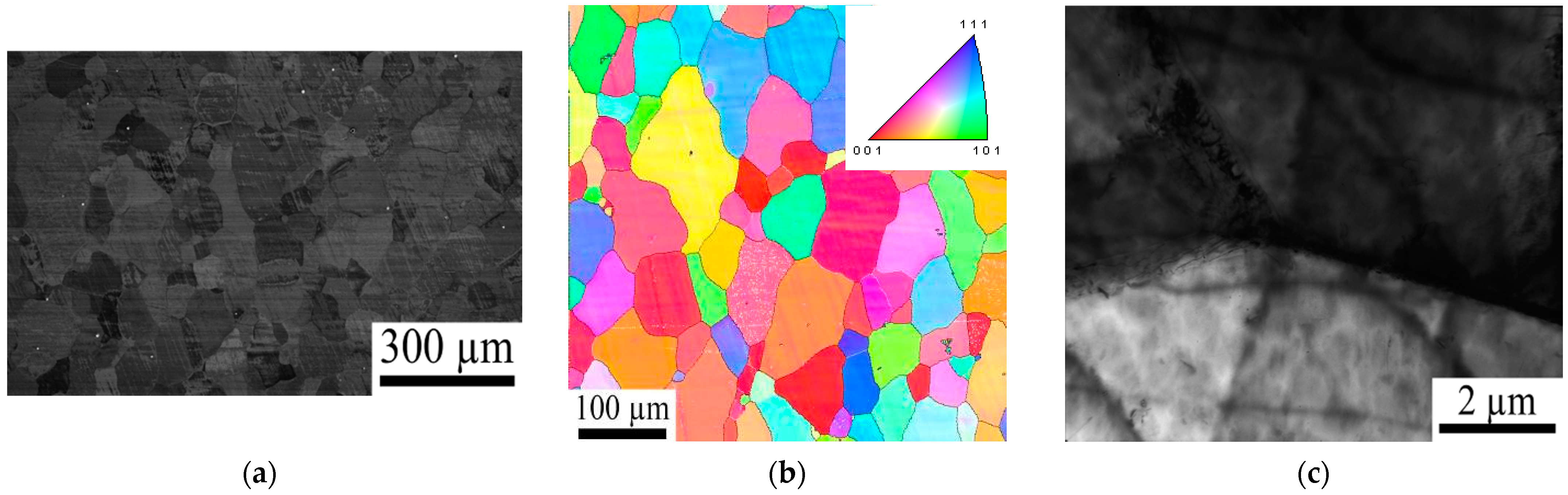
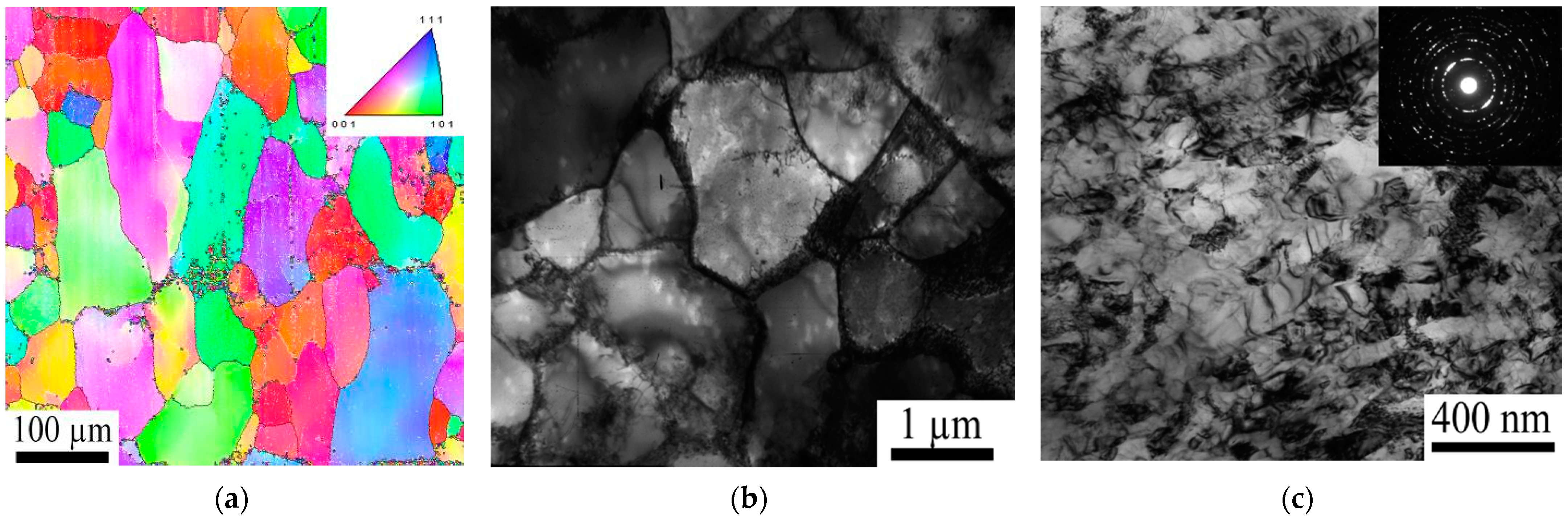
Material in the initial state has a uniform microstructure with a grain size of about 70 μm (
Figure 5a). TEM image (
Figure 5c) shows a low dislocation density in the ARMCO iron. EBSD analysis (
Figure 5b) shows that material structure is homogeneous. Therefore, it can be concluded that the investigated material has a nearly annealed structure.
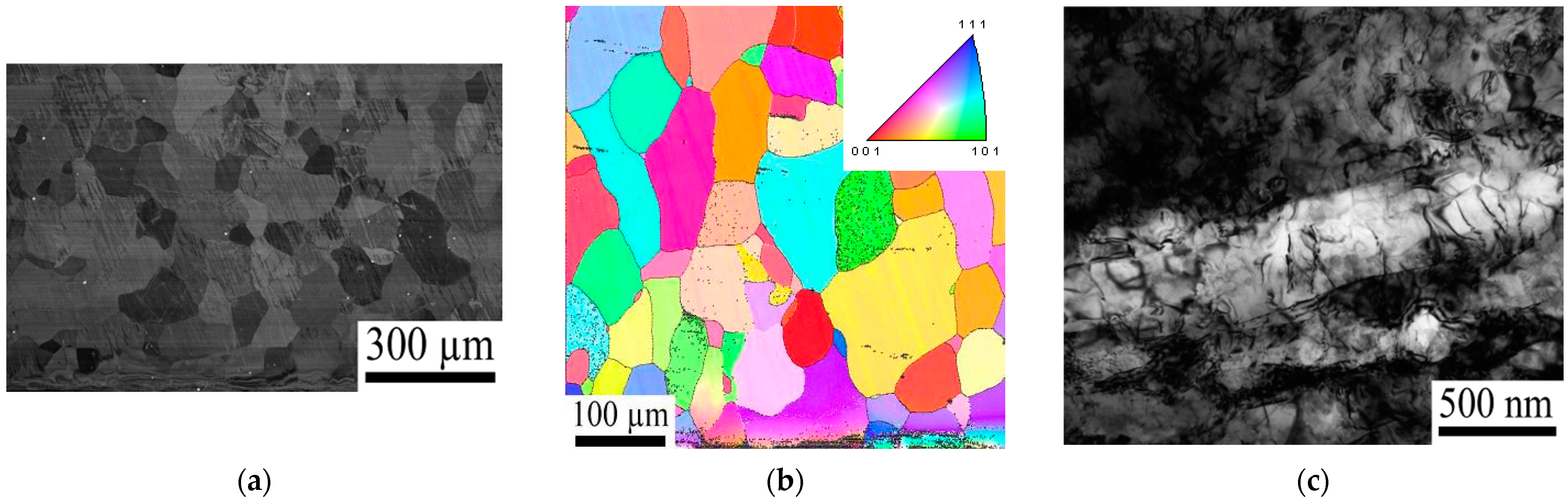
LSP induces considerable plastic deformation of the surface layer (
Figure 6a,b). The thickness of the layer with the visible distortion was about 25 μm. The microstructure below this layer did not noticeably change, in comparison with the initial state. EBSD analysis (
Figure 6b) also shows a homogeneous structure. TEM shows (
Figure 6c) a considerable increase in the dislocation density as a result of LSP treatment. In some places, dislocation pile-ups rearranged in sub-boundaries with a fringe contrast. Separate fragments of 100–500 nm can also be seen in the microstructure.
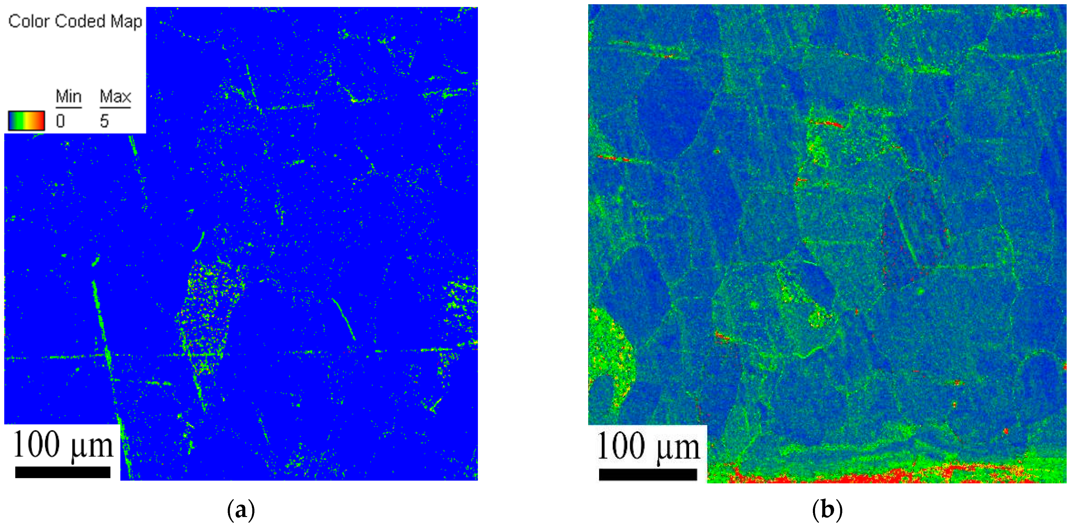
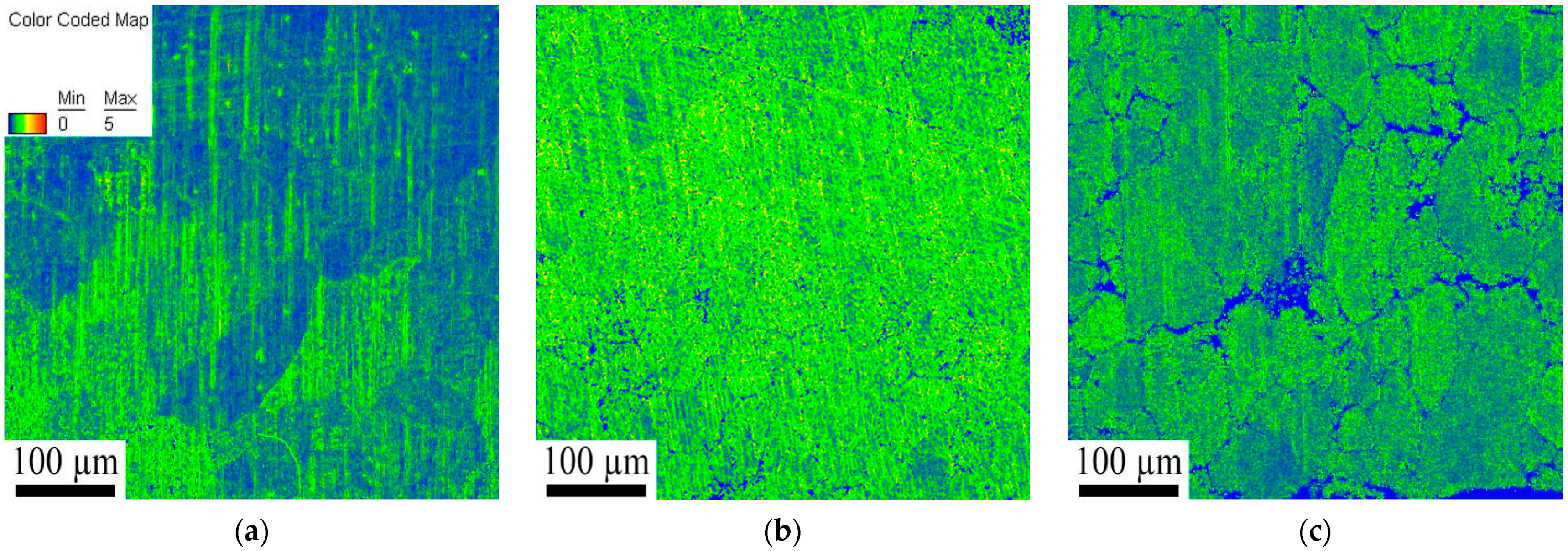
The kernel average misorientation map shows a very low level of local deformation in the initial state (
Figure 7a), which is confirmed by TEM results (
Figure 5c). After LSP treatment, the kernel map (
Figure 7b) displays a layer of about 30 μm with the maximum local misorientation. Similar results are observed in the SEM image (
Figure 6a). Moreover, local misorientations are increased in the whole scanned area, which allows the authors to conclude that the effect of LSP is not limited to 25 μm, but reaches the depth of at least 500 μm (size of the viewed area). In fact, a larger EBSD scan (not shown here) shows an increased level of distortion at the depth of even 1000 μm. These findings are in agreement with the data presented in
Figure 2 and the data reported earlier in [
28].
The fatigue test modified the microstructure in both cases, i.e., with and without LSP. Although neither SEM nor EBSD showed any noticeable changes (e.g.,
Figure 8a), the fatigue test of the non-treated sample led to some increase in the dislocation density; the dislocations were mainly observed near grain boundaries (
Figure 8b).
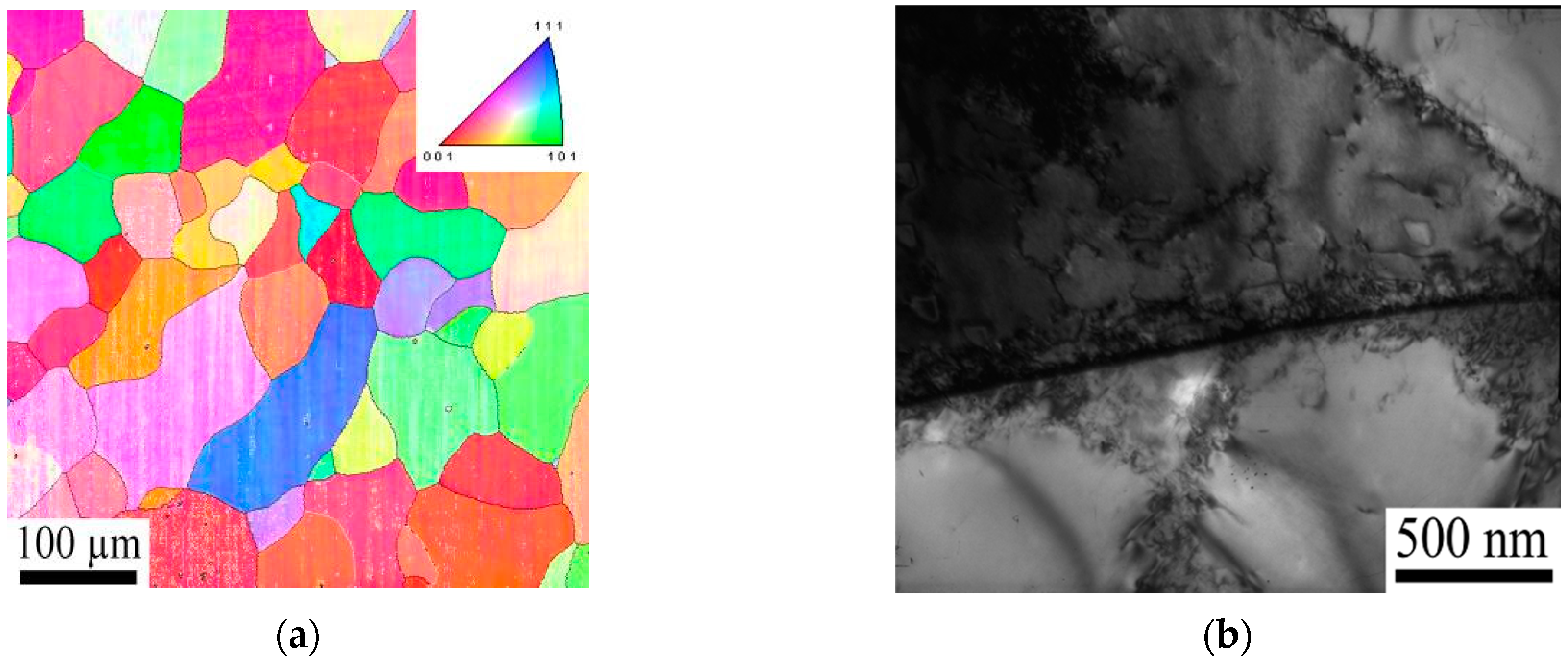
The fatigue test of the specimen modified by LSP resulted in more noticeable changes. The presence of the defect structures and substructures located mainly along grain boundaries can be observed in the EBSD map (
Figure 9a). TEM images obtained in the center of the specimen also show the dislocations at the grain boundaries (
Figure 9b). This microstructure is similar to the microstructure of the non-treated specimen after the fatigue test (
Figure 8b). However, the (sub)grain size in the specimen after LSP and the fatigue test was much smaller (~2 μm) (
Figure 8b and
Figure 9b). As the grain size in the EBSD map is nearly the same as in the initial state, the misorientation of these sub-boundaries is only a few degrees. More surprising was the severe microstructure refinement in the LSP modified surface after the fatigue test (
Figure 9c). The microstructure was elongated along the specimen axis; the size of the (sub)grains in the transversal direction was 100–150 nm. The dislocation density in the microstructure was relatively high. A ring-like selected area diffraction pattern (inserted in
Figure 9c) suggests a relatively high misorientation between the (sub)grains.
KAM analysis of the specimens with and without LSP after the fatigue test shows different responses to cyclic loading. For the non-treated sample, the fatigue test resulted in an increase in the level of local strain, especially in some grains which, most likely, had a “soft” orientation (i.e., with a high Schmid factor) with respect to the loading scheme.
Cyclic loading of the specimen after LSP resulted in a much higher level of KAM, thereby suggesting a higher local residual strain (
Figure 10b,c). The level of local strain was similar in the center of the specimen (
Figure 10b) and close to the surface (
Figure 10c). However, in the latter case, the misorientation of local strain near grain boundaries is above 5°. This is why these areas have been excluded from consideration, and are shown in a blue color in
Figure 10. A similar high local misorientation (5°, shown in blue) was observed at the bottom edge of the KAM map corresponding to the surface of the specimen.
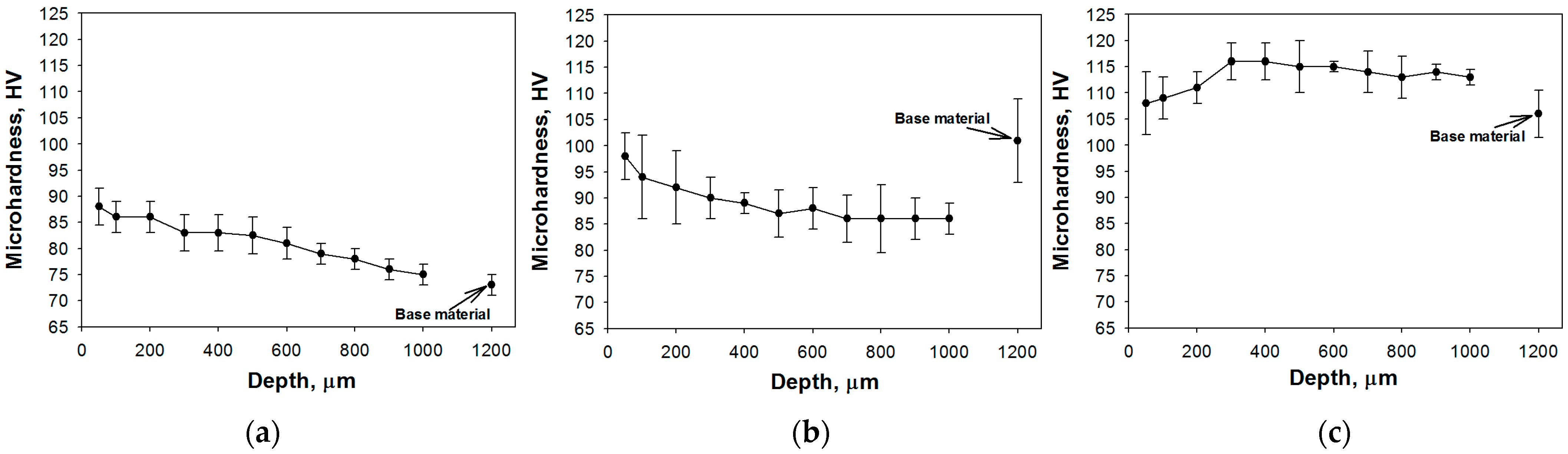
The microhardness of the specimen, measured from the surface towards the center of the specimen (
Figure 11), showed different mechanical properties, depending on the material state. The condition of the microhardness measurements was 2 N during 15 s. As expected, LSP increased the surface microhardness up to 87 HV (
Figure 11a). This value gradually decreased with depth, reaching the level of the initial state (73 HV).
For the specimen in the initial state, the fatigue test resulted in some softening (~15 HV) of the near-surface layer, in comparison to both surface and the base material (
Figure 11b). This microhardness profile can possibly be associated with a heterogeneous strain distribution across the specimens during cyclic loading.
The qualitatively different profile was observed in the specimen modified by LSP surface after the fatigue test (
Figure 11c). Irrespective of the microstructure refinement in the surface layer, the microhardness at a depth of 20 μm was rather low (107 HV), in comparison with deeper layers. The maximum microhardness of 117 HV was attained at a depth of ~400 μm, and then slightly decreased with depth. The microhardness of the base material was found to be 106 HV, i.e., higher than in other specimens.
The microhardness values of the sample subjected to LSP were maximum in the surface zone, ~100 µm, which is consistent with the results of kernel average misorientation (KAM) analysis, where KAM maps showed a low level of local deformation in the initial state (
Figure 7a) and after LSP (
Figure 7b). As expected, the kernel maps display a layer of about 30 µm in the maximum local misorientation. In addition, it is noted that the microhardness values of the samples subjected to the fatigue tests are higher compared to the initial sample after LSP, and the microhardness curves are uniform in the distribution of the depth of the work pieces (
Figure 11b,c). Characteristically, the uniformity of the distribution of the qualitative values of the dislocation density for the sample can also be traced on KAM maps, taken from the central and surface zones after LSP treatment and fatigue tests (
Figure 10b,c).
The analysis of the microstructure and microhardness distribution suggest a rather pronounced effect of LSP on the fatigue behavior of ARMCO iron. Cyclic loading itself resulted in some increase in dislocation density and hardness (
Figure 8,
Figure 10a and
Figure 11b), which were more or less homogeneous through the cross-section. LSP additionally increases these parameters near the surface (up to 1 mm thickness [
6]), even leading to considerable grain refinement (
Figure 9,
Figure 10a,b and
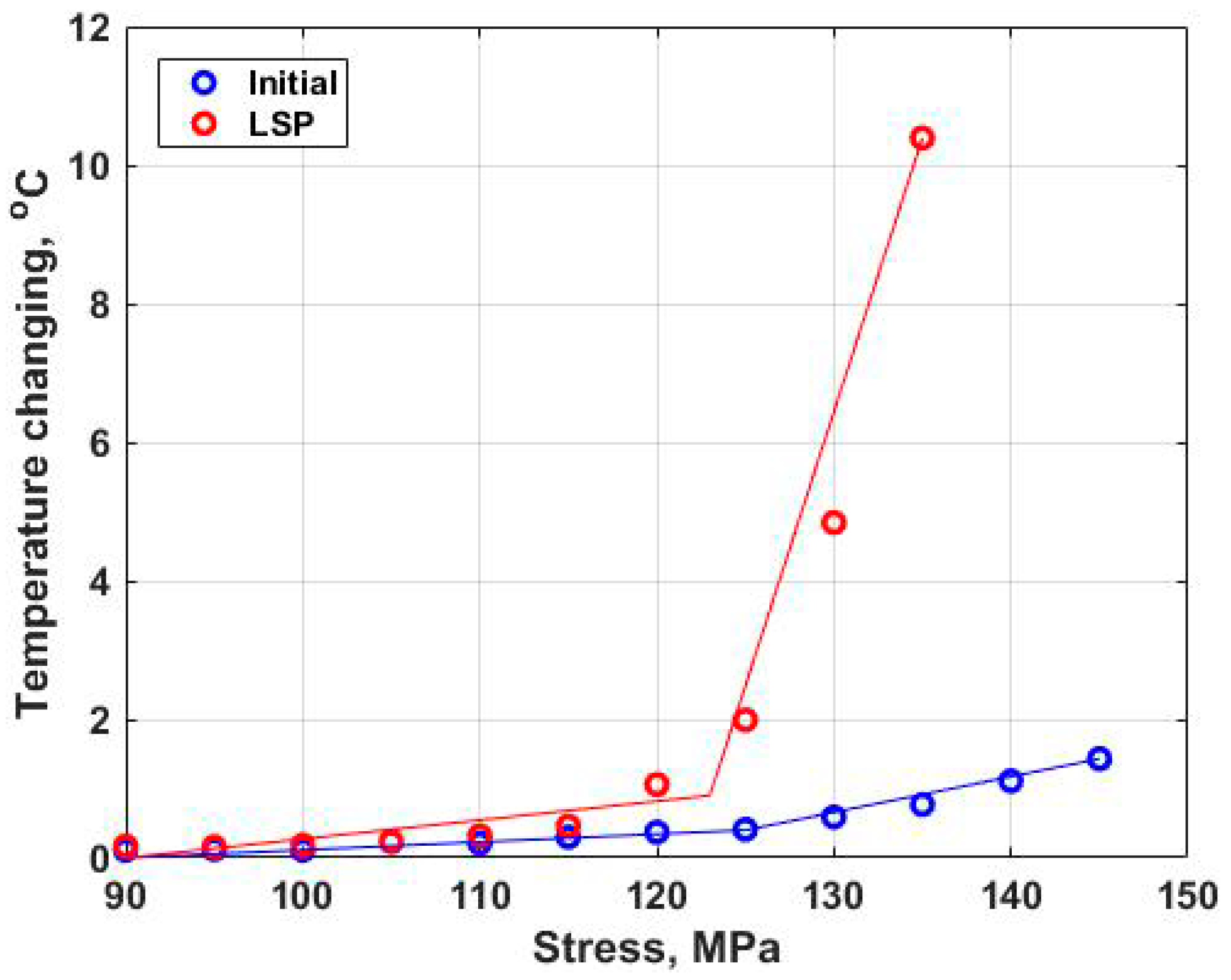
Figure 11c). This aggregate effect of two treatments (cyclic loading and LSP) gives rise to a greater amount of latent elastic energy, which can be released faster during the fatigue test (
Figure 3). Similar results were earlier observed during the fatigue test of specimens after severe plastic deformation, in comparison with specimens in the initial (undeformed) condition [
19].
Author Contributions
Conceptualization, O.P., N.K. and S.Z.; Investigation, A.P., A.V., F.F. and M.O.; Project administration, O.P., N.K. and S.Z.; Writing—original draft, A.P.; Writing—review & editing, O.P., N.K., F.F., M.O. and S.Z. All authors have read and agreed to the published version of the manuscript.
Funding
This research was funded by Ministry of Education and Science of the Russian Federation (Agreement No. 075-15-2020-925 of 16 November 2020).
Data Availability Statement
Data presented in this article are available at request from the corresponding author.
Acknowledgments
This paper was prepared in the framework of the program for the creation and development of the world-class scientific center “Supersonic” for 2020–2025, with the financial support of the Ministry of Education and Science of the Russian Federation.
Conflicts of Interest
The authors declare no conflict of interest.
References
- McClung, R.C. A literature survay on the stability and significance of residual stresses during fatigue. Fatigue Fract. Eng. Mater. Struct. 2007, 30, 173–205. [Google Scholar] [CrossRef]
- Liu, Q.; Baburamani, P.; Loader, C. Effect of High Temperature Exposure on the Mechanical Properties of Cold Expanded Open Holes in 7050-T7451 Aluminium Alloy; Report No. DSTO-TN-0844; Air Vehicles Division, DSTO Defence Science and Technology Organisation: Melbourne, Australia, 2008.
- LAMBDA Technology Group. Low Plasticity Burnishing. 23 August 2013. Available online: http://www.lambdatechs.com/low-plasticity-burnishing-LPB.html (accessed on 20 July 2021).
- Jayaraman, N.; Hornbach, D.J.; Prevey, P.S. Mitigation of Fatigue and Pre-Cracking Damage in Aircraft Structures through Low Plasticity Burnishing (LPB). In Proceedings of the ASIP, Palm Springs, CA, USA, 4–6 December 2007. [Google Scholar]
- Schnubel, D.; Horstmann, M.; Ventzke, V.; Riekehr, S.; Staron, P.; Fischer, T.; Huber, N. Retardation of Fatigue Crack Growth in Aircraft Aluminium Alloys via Laser Heating-Experimental Proof of Concept. Mater. Sci. Eng. 2012, 546, 8–14. [Google Scholar] [CrossRef] [Green Version]
- Ding, K.; Ye, L. Laser Shock Peening: Performance and Process Simulation; Woodhead Publishing Ltd.: Cambridge, UK, 2006. [Google Scholar]
- Askar’Yan, G.A.; Moroz, E.M. Pressure on evaporation of matter in a radiation beam. J. Exp. Theor. Phys. Lett. 1963, 16, 1638–1644. [Google Scholar]
- Neuman, F. Momentum Transfer and Cratering Effects Produced by Giant Laser Pulses. Appl. Phys. Lett. 1964, 4, 167–169. [Google Scholar] [CrossRef]
- Braginskii, V.B.; Minakova, I.I.; Rudenko, V.N. Some Mechanical Effects in the Interaction between Pulsed Electromagnetic Radiation and a Metal (in Russian). J. Exp. Theor. Phys. 1967, 37, 1045–1051. [Google Scholar]
- Skeen, C.H.; York, C.M. Laser Induced “Blow-off” Phenomena. Appl. Phys. Lett. 1968, 12, 369–371. [Google Scholar] [CrossRef]
- LSP Technology. What Is Laser Peening. Available online: http://www.lsptechnologies.com/ (accessed on 20 July 2021).
- Peyre, P.; Fabbro, R.; Merrien, P.; Lieurade, H. Laser shock processing of aluminium alloys. Application to high cycle fatigue behaviour. Mater. Sci. Eng. 1996, 210, 102–113. [Google Scholar] [CrossRef]
- Fabbro, R.; Peyre, P.; Berthe, L.; Scherpereel, X. Physics and applications of laser-shock processing. J. Laser Appl. 1998, 10, 265–279. [Google Scholar] [CrossRef]
- Berthe, L.; Fabbro, R.; Peyre, P.; Bartnicki, E. Experimental study of the transmission of breakdown plasma generated during laser shock processing. Eur. Phys. J. Appl. Phys. 1998, 3, 215–218. [Google Scholar] [CrossRef]
- Brockman, R.A.; Braisted, W.R.; Olson, S.E.; Tenaglia, R.D.; Clauer, A.H.; Langer, K.; Shepard, M.J. Prediction and characterization of residual stresses from laser shock peening. Int. J. Fatigue 2012, 36, 96–108. [Google Scholar] [CrossRef]
- Keller, S.; Chupakhin, S.; Staron, P.; Maawad, E.; Kashaev, N.; Klusemann, B. Experimental and numerical investigation of residual stresses in laser shock peened AA2198. J. Mater. Process. Tech. 2018, 255, 294–307. [Google Scholar] [CrossRef]
- Sticchi, M.; Schnubel, D.; Kashaev, N.; Huber, N. Review of residual stress modification techniques for extending the fatigue life of metallic aircraft components. Appl. Mech. Rev. 2015, 67, 010801-1. [Google Scholar] [CrossRef]
- La Rosa, G.; Risitano, A. Thermographic methodology for rapid determination of the fatigue limit of materials and mechanical components. Int. J. Fatigue 2000, 22, 65–73. [Google Scholar] [CrossRef]
- Plekhov, O.A.; Naimark, O.B.; Valiev, R.Z.; Semenova, I.P.; Saintier, N.; Palin-Luc, T. Experimental investigations of anomalous energy absorption in nanocrystalline titanium under cyclic loading conditions. Tech. Phys. Lett. 2008, 34, 557. [Google Scholar] [CrossRef]
- Wei, W.; Li, C.; Sun, Y.; Xu, H.; Yang, X. Investigation of the Self-Heating of Q460 Butt Joints and an S-N Curve Modeling Method Based on Infrared Thermographic Data for High-Cycle Fatigue. Metals 2021, 11, 232. [Google Scholar] [CrossRef]
- Guo, S.; Liu, X.; Zhang, H.; Yan, Z.; Fang, H. Fatigue Limit Evaluation of AZ31B Magnesium Alloy Based on Temperature Distribution Analysis. Metals 2020, 10, 1331. [Google Scholar] [CrossRef]
- Naksuk, N.; Nakngoenthong, J.; Printrakoon, W.; Yuttawiriya, R. Real-Time Temperature Measurement Using Infrared Thermography Camera and Effects on Tensile Strength and Microhardness of Hot Wire Plasma Arc Welding. Metals 2020, 10, 1046. [Google Scholar] [CrossRef]
- Crupi, V.; Epasto, G.; Guglielmino, E.; Marinò, A. Influence of Weld-Porosity Defects on Fatigue Strength of AH36 Butt Joints Used in Ship Structures. Metals 2021, 11, 444. [Google Scholar] [CrossRef]
- Ferro, A.; Montalenti, G. Fatigue of pure iron and of iron containing a small quantity of carbon after strain ageing. Philos. Mag. 1963, 8, 105–119. [Google Scholar] [CrossRef]
- Bruder, E. Mechanical Properties of ARMCO® Iron after Large and Severe Plastic Deformation—Application Potential for Precursors to Ultrafine Grained Microstructures. Metals 2018, 8, 191. [Google Scholar] [CrossRef] [Green Version]
- Muñoz, J.A.; Higuera, O.F.; Cabrera, J.M. High cycle fatigue of ARMCO iron severely deformed by ECAP. Mater. Sci. Eng. A 2017, 681, 85–96. [Google Scholar] [CrossRef] [Green Version]
- Kashaev, N.; Ventzke, V.; Horstmann, M.; Chupakhin, S.; Riekehr, S.; Falck, R.; Maawad, E.; Staron, P.; Schell, N.; Huber, N. Effects of laser shock peening on the microstructure and fatigue crack propagation behaviour of thin AA2024 specimens. Int. J. Fatigue 2017, 98, 223–233. [Google Scholar] [CrossRef] [Green Version]
- Montross, C.S.; Wei, T.; Ye, L.; Clark, G.; Mai, Y.W. Laser shock processing and its effects on microstructure and properties of metal alloys: A review. Int. J. Fatigue 2002, 24, 1021–1036. [Google Scholar] [CrossRef]
- Steinzig, M.; Ponslet, E. Residual stress measurement using the hole drilling method and laser speckle interferometry: Part 1. Exp. Tech. 2003, 27, 43–46. [Google Scholar] [CrossRef]
- Toparli, M.B.; Fitzpatrick, M.E. Effect of overlapping of peen spots on residual stresses in laser-peened aluminium sheets. Metall. Mater. Trans. A 2019, 50, 1109–1112. [Google Scholar] [CrossRef]
- Kallien, Z.; Keller, S.; Ventzke, V.; Kashaev, N.; Klusemann, B. Effect of laser peening process parameters and sequences on residual stress profiles. Metals 2019, 9, 655. [Google Scholar] [CrossRef] [Green Version]
- Luong, M.P. Infrared thermographics scanning of fatigue in metals. Nucl. Eng. Des. 1995, 158, 363–376. [Google Scholar] [CrossRef] [Green Version]
- Ivetic, G.; Meneghin, I.; Troiani, E.; Molinari, G.; Ocaña, J.L.; Morales, M.; Porro, J.; Lanciotti, A.; Ristori, V.; Polese, C.; et al. Fatigue in laser shock peened open-hole thin aluminium specimens. Mater. Sci. Eng. A 2012, 534, 573–579. [Google Scholar] [CrossRef] [Green Version]
Figure 1.
Geometry of samples for mechanical tests. All dimensions are in mm.
Figure 2.
The residual stress distribution in an ARMCO iron sample after LSP. The
x-axis (σ
xx) is parallel to the length of the specimen for the fatigue test in
Figure 1.
Figure 3.
Surface temperature evolution vs. applied stress amplitude for the fatigue specimen without LSP treatment (initial), and the fatigue specimen with LSP treatment.
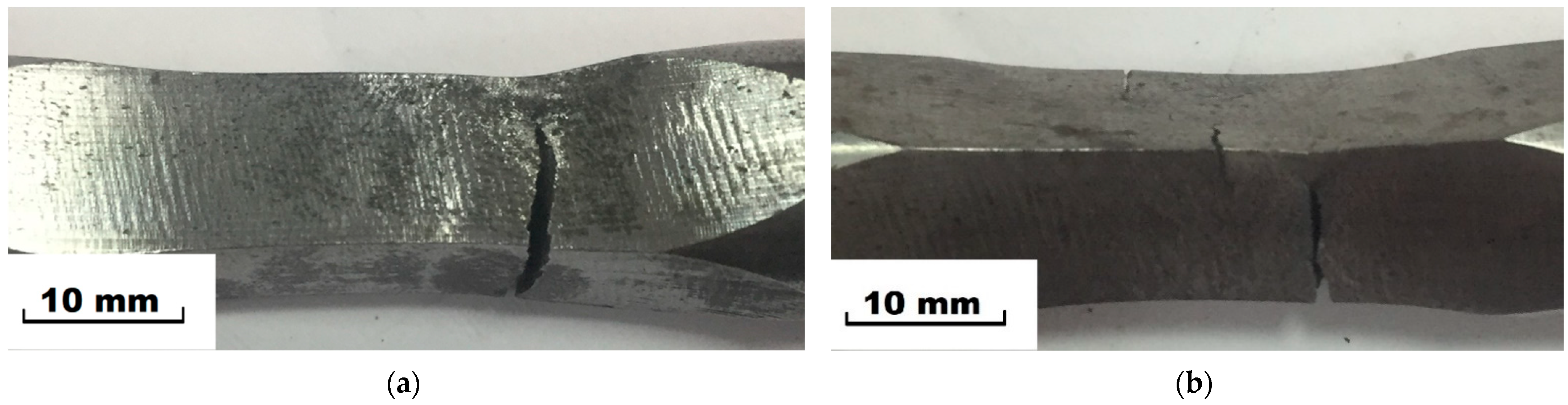
Figure 4.
Specimens after fatigue tests, (a) initial condition, (b) after LSP.
Figure 5.
Microstructure of ARMCO iron in the initial state: (a) SEM image, (b) EBSD IPF map and (c) TEM image; the bottom edge of the SEM image corresponds to the surface of the specimen.
Figure 6.
Microstructure of ARMCO iron after LSP: (a) SEM image, (b) EBSD IPF map and (c) TEM image; the bottom edge of the SEM image corresponds to the surface of the specimen.
Figure 7.
Kernel average misorientation maps of surface layers of ARMCO iron in the initial state (a) and after LSP (b); the bottom edge of the images corresponds to the surface of the specimen.
Figure 8.
Microstructure of ARMCO iron in the initial state after the fatigue test: (a) EBSD IPF map and (b) TEM images; the bottom edge of the EBSD map corresponds to the surface of the specimen.
Figure 9.
Microstructure of ARMCO iron after LSP and fatigue test: (a) EBSD IPF map and (b,c) TEM images; (b) the image was obtained in the center of the specimen and (c) at the surface layer and selected area diffraction pattern. The bottom edge of the EBSD map corresponds to the surface of the specimen.
Figure 10.
Kernel average misorientation maps of surface layers in ARMCO iron after the fatigue test for the initial (a) and LSP treated samples (b,c); (b) was obtained in the center of specimen and (c) was obtained at the surface layer. The bottom edge of the images (a,c) corresponds to the surface of the specimen.
Figure 11.
Distribution of microhardness from surface towards the ARMCO iron specimen center after LSP (a), without LSP after fatigue test (b) and after LSP and the fatigue test (c); microhardness for the base material was measured in the center of the specimens.
Table 1.
The chemical composition of ARMCO iron (wt.%).
| Fe | C | Si | Mn | Ni | S | Mo | Cr | P |
|---|
| ~99 | 0.004 | 0.05 | 0.04 | 0.06 | 0.005 | 0.01 | 0.038 | 0.005 |
Table 2.
Number of cycles to failure for the tested specimens.
| Specimen | LSP | Number of Cycles to Failure |
|---|
| Sp5 | Yes | 1.18 × 10⁵ |
| Sp4 | Yes | 9.12 × 10⁴ |
| Sp3 | No | 7.50 × 10⁵ |
| Sp6 | No | >3.00 × 10⁶ (run out) |
| Publisher’s Note: MDPI stays neutral with regard to jurisdictional claims in published maps and institutional affiliations. |
© 2021 by the authors. Licensee MDPI, Basel, Switzerland. This article is an open access article distributed under the terms and conditions of the Creative Commons Attribution (CC BY) license (https://creativecommons.org/licenses/by/4.0/).


 ,
, 


