An Overview of Underwater Connectors


1
Zhejiang University–Westlake University Joint PhD Program, Zhejiang University, Hangzhou 310058, China
2
Key Laboratory of Coastal Environment and Resources of Zhejiang Province, School of Engineering, Westlake University, Hangzhou 310024, China
3
Institute of Advanced Technology, Westlake Institute for Advanced Study, Hangzhou 310024, China
*
Author to whom correspondence should be addressed.
J. Mar. Sci. Eng. 2021, 9(8), 813; https://doi.org/10.3390/jmse9080813
Submission received: 21 June 2021
/
Revised: 23 July 2021
/
Accepted: 23 July 2021
/
Published: 27 July 2021
(This article belongs to the Section Ocean Engineering)
Abstract
:Underwater connectors are very essential and complex components of deep-sea engineering equipment and their design and manufacture have apparent multidisciplinary characteristics. Wet-mateable connectors (WMCs) represent the highest level of technology in this field, and only a very few countries in the world can produce WMCs. So, WMCs are likely to be a constraining factor to some maritime powers that might try to achieve breakthroughs in this field, constraining the innovation-driven development of deep-sea equipment. This paper gives a detailed overview of underwater connectors, both electrical and optical. First, the background of underwater connectors is introduced, and then the main available commercial off-the-shelf (COTS) products are described. Next, the new concept of functional units is proposed by the authors to help readers to have a better understanding of underwater connectors. Then, the basic theories of design are introduced according to different functional units, covering the aspects of electrical/optical connection, pressure-balanced oil-filled (PBOF) technology, penetrable self-sealing, aligning and locking structures. Finally, some discussions and conclusions are presented. This paper aims to reveal the secrets of key technologies used in underwater connectors, especially in WMCs.
1. Introduction
When 70.8% of our planet’s surface is covered by oceans, it seems perplexing that the Earth is called “Earth” [1]. Today, we have more detailed maps of the surface of the moon, while we have just explored less than 20% of this vast underwater realm, only 5% in detail [2,3]. The ocean, with the deepest part of approximately 11,034 m, has abundant resources (e.g., minerals, living creatures, genes, renewable energy, space, etc.), which are essential sources for human beings to achieve sustainable development [4]. The strategic development and deep utilization of marine resources have become an important index to evaluate a country’s comprehensive national power [5]. As the frontier region of ocean exploration, the hadal zone (depth of 6000 to 11,000 m) has lured explorers for decades [6]. Within the range of this depth, we can call it veritable “deep-sea”.
Efficient technical equipment is fundamental for the effective exploration and utilization of this vast blue ecological system [7]. Many manned and unmanned submersibles have been developed, such as remotely operated vehicles (ROVs) [8], autonomous underwater vehicles (AUVs) [7,9,10], human-occupied vehicles (HOVs) [10,11,12,13], and hybrid ROV and AUV (HROV or ARV) [14]. Many undersea observatories have been built [15], such as the Hawaii Undersea Geo-Observatory (HUGO) [16] and the Astronomy with a Neutrino Telescope and Abyss environmental RESearch (ANTARES) project [17,18]. Various kinds of marine engineering equipment have also been deployed, to exploit oil and gas, as well as offshore renewable energy (ORE) farms.
For submersibles, cables and connectors are the vital power and communication channels, corresponding to our human blood vessels and nerves [5]. Underwater connectors are the “articulus” of cables, which makes them undoubtedly become one of the most significant components of deep-sea equipment. It seems that most unsuccessful underwater and offshore projects are due to connection failures [19]. Just as Paul G. Slade says, the obsolescence of connectors occurs not in one’s life, but within one’s recent memory [20].
Essentially, underwater connectors can be categorized into dry-mateable connectors (DMCs) and wet-mateable connectors (WMCs). As the names suggest, the difference between DMCs and WMCs is whether connectors can be mated and de-mated in the subsea environment [19]. WMCs can reduce the time and the cost of total productive maintenance (TPM), and can provide an effective solution for the expansion and networking of the deep-sea system [21]. Dry-mate and wet-mate are two completely different technical challenges, and only a very few countries in the world can produce WMCs. WMCs represent the highest level of technology in this field, and the whole market is monopolized by several companies. Due to technical blockage by several developed countries, WMCs have become one of the 35 bottleneck techniques announced by China’s Science and Technology Daily in 2018.
To the authors’ knowledge, only one review paper on underwater connectors, written by Rémouit et al. [19], has been found. This paper provides a detailed overview of underwater electrical connectors, including a brief history, the main commercial types, and basic design principles. However, underwater optical connectors are not focused on in that paper, but they are normally the most difficult challenge. Furthermore, the key technologies of underwater connectors should be distilled from the main available top commercial off-the-shelf (COTS) products.
This paper aims to give a review on the state-of-the-art of underwater connectors, including both electrical and optical. As a result of the complicated structure of underwater connectors, the concept of functional units is proposed by the authors, which could be helpful for a better understanding of underwater connectors and the classification of their key technologies.
This paper consists of six parts after this introduction. In Section 2, the background of underwater connectors is introduced; the main available top COTS products are presented; and the concept of functional units of underwater connectors are proposed. Section 3 elaborates on the basic knowledge of electrical contacts and optical connections. Section 4 presents some basic types of sealing and pressure-balanced designs of underwater connectors. Section 5 introduces the aligning and locking structures of underwater connectors. Section 6 contains some discussions and conclusions.
2. Background and Functional Units
2.1. Characteristics, Classfication and Terminologies
Compared with general connectors, underwater connectors are more difficult to design. In general, the cost of developing an underwater connector is very high. It has to not only meet the specifications of the connector itself, but also ensure the reliability and stability of connection in a harsh underwater environment. Thus, the design of underwater connectors has obvious multidisciplinary characteristics, which involve electromagnetics, optics, mechanical engineering, electrical engineering, materials science, tribology and other disciplines.
The global market of underwater connectors is prosperous, because underwater connectors are widely used in a lot of fields, such as submersibles, oil and gas industry, ORE farms, underwater observatories, and so on. The detailed information of the abovementioned domains can be found in the review paper of Rémouit et al. [19].
In addition, as penetration components, underwater connectors play an essential role in the development of deep-ocean simulation systems (DOSs) that can provide an ideal means to perform pressure testing to validate the integrity of any marine equipment [22]. For DOSs, pressure control systems, data and images acquisition, and even the power supply for test models all need reliable underwater connectors to complete the internal and the external connection of cables [4,23]. This is another important application area of underwater connectors.
There are many other classification methods for underwater connectors, apart from the above-mentioned DMCs and WMCs. Based on signal types, underwater connectors can be divided into electrical, optical and hybrid connectors. A hybrid underwater connector has both electrical and optical channels. Moreover, underwater connectors can be classified according to different structures: rubber molded (RM) or plastic molded (PM), bulkhead (BH) or rigid-shell, pressure-balanced oil-filled (PBOF), inductive coupling (IC), and so on. The detailed descriptions of them can also be found in the review paper of Rémouit et al. [19]. Otherwise, underwater connectors can also be classified by voltage, current or pressure rating (e.g., low, medium, high, or very high, etc.) [24].
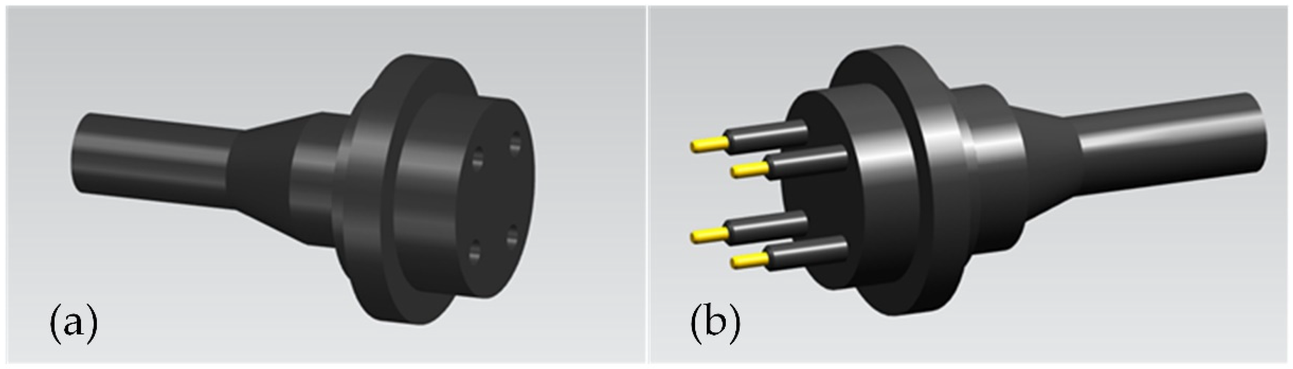
Now, we can define a complete underwater connector system as two parts: plug connector and receptacle connector. To simplify, we can call them plug and receptacle (or socket), respectively. The plug generally has one or more pins (or probes), while the receptacle contains the same number of matched sockets. Thus, male connector and female connector are commonly used to refer to plug and receptacle, respectively, even “male” and “female” for short. For connectors with complex structures, especially for optical connectors, it can be difficult to determine which is a “male” or a “female”, according to the definition mentioned above. The definition of what is a plug and what is a receptacle is not very strict. It is just a way to distinguish the two parts of one underwater connector system in one patent reference or in one serial of products. Furthermore, when a plug and a receptacle stay connected, it can be called mating state; and when the two parts disconnected, it is called de-mating state. Figure 1 depicts a basic 3D CAD view of a common underwater electrical connector.
2.2. History
The history of underwater connectors can be traced back to 1858, when the Atlantic Telegraph was installed successfully after many setbacks. It was the first telegraph communication in the world, which gave birth to underwater electrical connectors. This is why Rémouit et al. think that underwater connectors have more than 150 years of history [19]. However, connecting the two electrical cables for underwater application in the early days was accomplished in some makeshift ways, for example, splicing the two parts of the conductors together with tubing rubber over the junction [25].
Prior to the Second World War, there was no imperative requirement to produce special connectors for underwater application [26]. Until the early 1950s, the first underwater electrical connector was invented and then soon formed a market. The first connectors were dry-mateable RM and rigid-shell connectors, which are still in use today with their original forms [19]. So actually, underwater connectors may only have a short history of about 70 years. Since then, the needs of underwater electrical connectors have grown rapidly in response to both military and oil industry applications [25]. In the 1960s, the wet-mateable PBOF connectors were introduced, which greatly improved their reliability and functionality, making the market substantial [27]. Furthermore, during this period, engineers began to study how to apply the powerful optical fibers to the underwater system [28]. In the 1970s, the IC connectors were created, but they were never widely used due to the limitations of power and bandwidth [26]. During the 1960s and 1970s, the Golden Age of human exploration in the deep-sea, pushed by oil exploration by the United Kingdom and Norway under the North Sea, the market of underwater connectors grew rapidly once again [29]. In the 1980s, the first optical WMC was invented, and meanwhile, the optical DMCs were offered commercially. In the 1990s, the hybrid WMCs were developed by Ocean Design Inc. (ODI), which combined the best technologies [26].
By the time of the 21st century, thousands of different products with mature technologies were offered in the market worldwide [19]. Each manufacturer has its own unique technologies, and this will be illustrated next. Nowadays, the development of communication engineering has a hectic pace, which attracts researchers to design noncontact underwater connectors. Based on the ideas of IC connectors, modern transmission technologies (e.g., Bluetooth, Wi-Fi, optical infrared, acoustic modems, radio frequency, etc.) were increasingly applied to realize the wireless connection of data transmission in underwater application. However, these connectors will not be a concern of this paper, and can be found in the related references [24,30,31,32,33,34,35,36].
2.3. Main Available COTS Connectors
Today, the globally famous vendors of underwater connectors include Tyco Electronics (TE) Connectivity Ltd. (has acquired SEACON), MacArtney Underwater Technology Group, Teledyne Marine Group (has acquired ODI), and so on. Table 1 lists the main specifications of some first-class WMCs of the above three manufacturers.
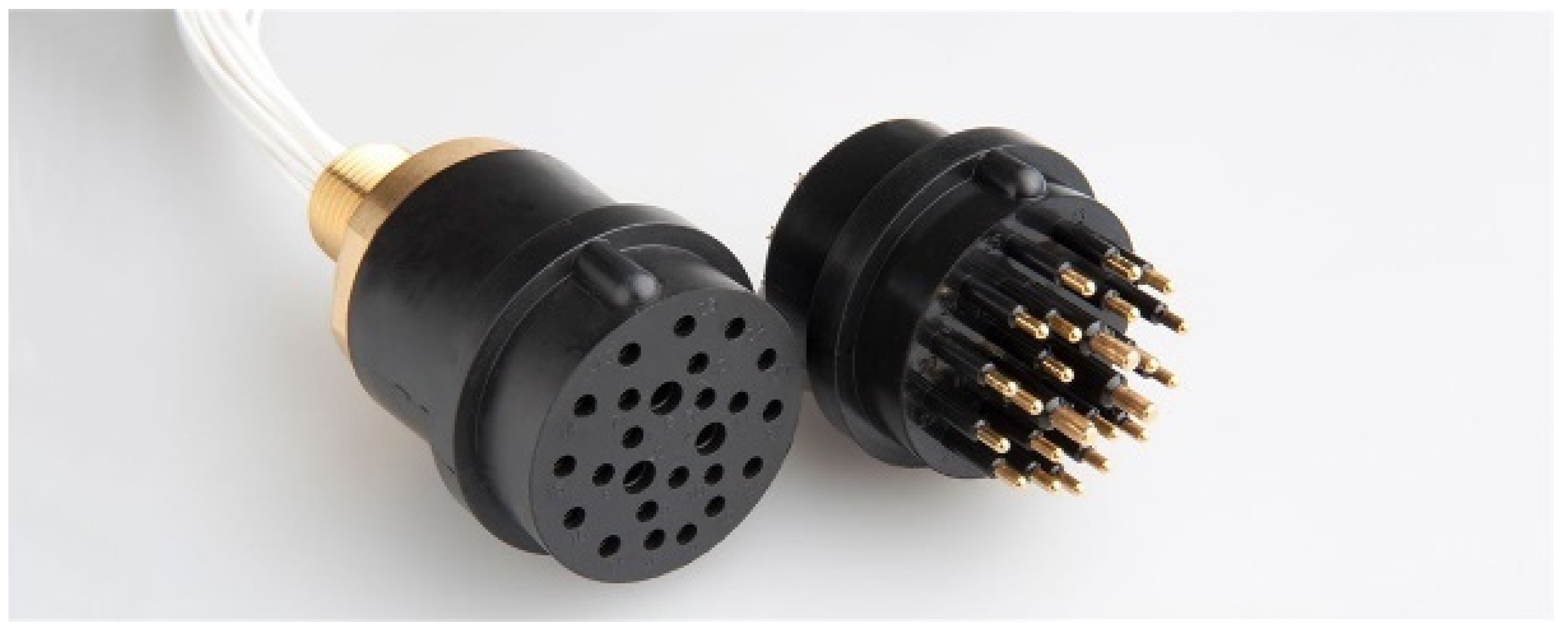
The SEACON Group (founded in 1964), a leading provider of underwater connector technology and systems, has more than 50 years of history. In the 1970s, SEACON began to supply underwater electrical connectors [37], and in the 1980s, SEACON introduced the MINI-CON electrical DMC with great success, and developed its electrical WMCs in the 1990s. Among them, the ALL-WET can be operated in full-ocean-depth (FOD) conditions, while the HydraElectric, a follow-up product, adopted the design of PBOF and shuttle pins. At the same time, the first optical WMC Hydra Star was also introduced, and its improved version the HydraLight (Figure 2) came out in 2000. SEACON used the design of ultra-physical contact (UPC) and angled-physical contact (APC) in the HydraLight, which can greatly improve the performance of the optical fiber connection. The innovative third generation of underwater optical connectors G3 was put into the market in 2010. Then, SEACON combined the advantages of the HydraLight and the G3 to produce the High Capacity Optical WMC (Figure 2) whose number of contacts increased six times at the same size of last generation [28]. In 2014, SEACON was acquired by TE Connectivity, another world leader in connectivity.
The MacArtney Group is a global supplier of underwater technology products and systems and was founded in 1978. Its most famous brand of underwater electrical connectors may be the SubConn® (Figure 3) of SubConn Inc., which has almost 40 years of history. The most representative and recognizable feature of the SubConn® connector is its red cap. The low-end series of the SubConn® Circular has big sales in the global market. Another well-known brand of underwater optical connectors is the OptoLink (Figure 4), and the multi-mode and single-mode optical fiber connectors were developed in 1986 and 1996, respectively. The distinctive technology of OptoLink is its optical connection type with expanded-beam ball lens. The lens protects the end-faces of the optical fibers, which is convenient for fiber cleaning and assembling.
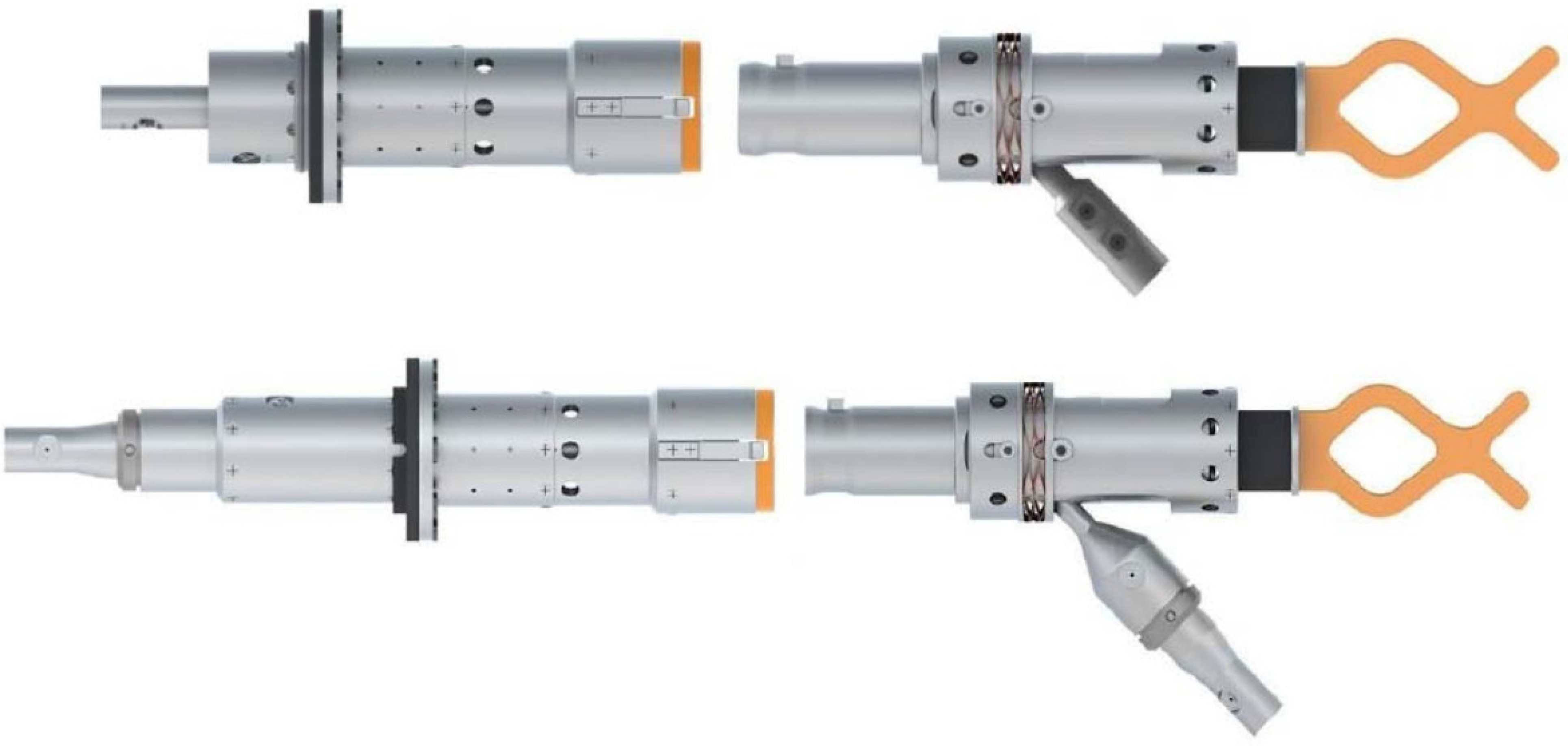
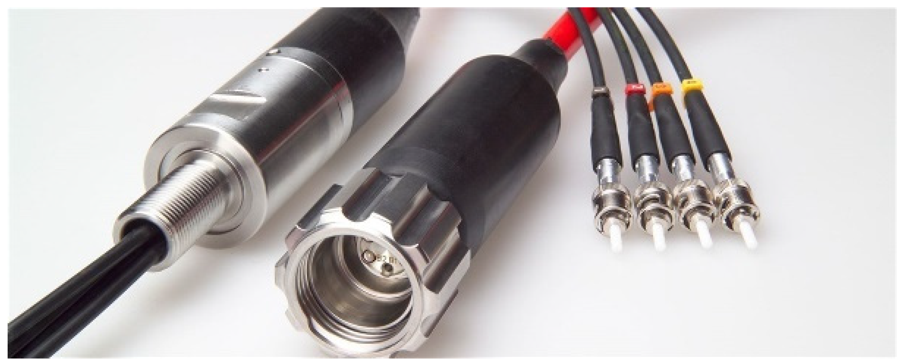
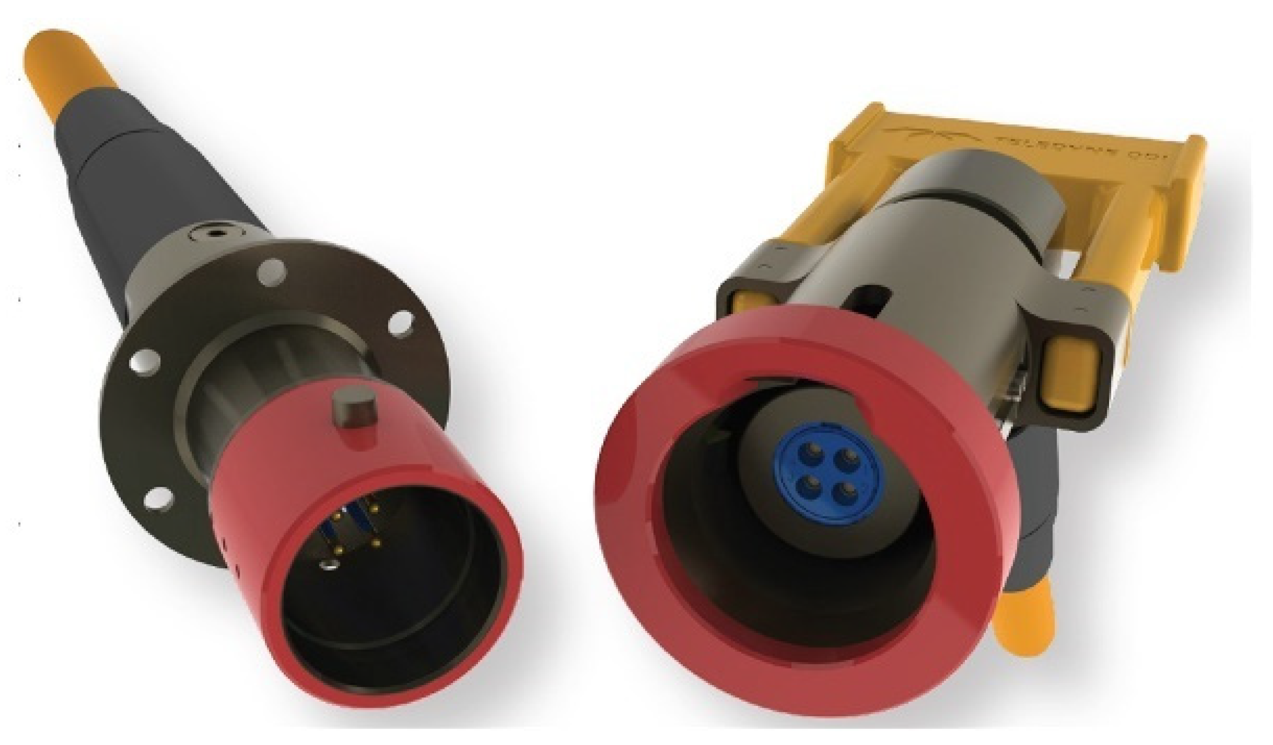
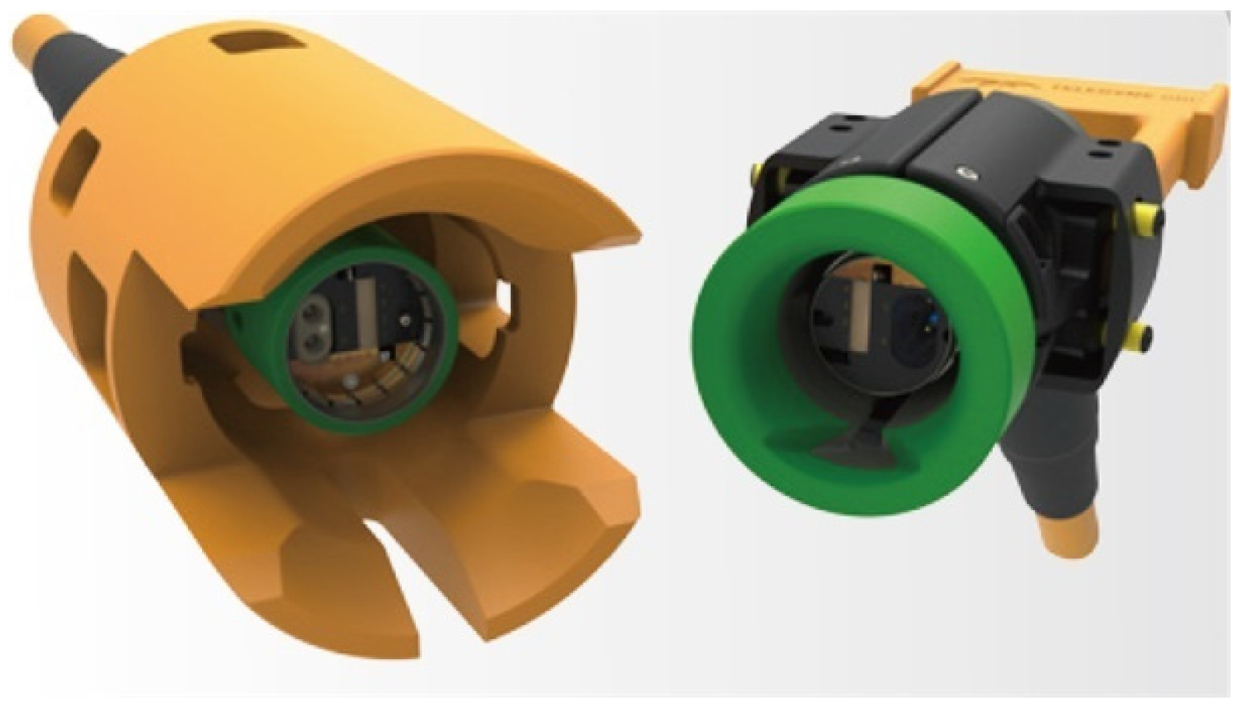
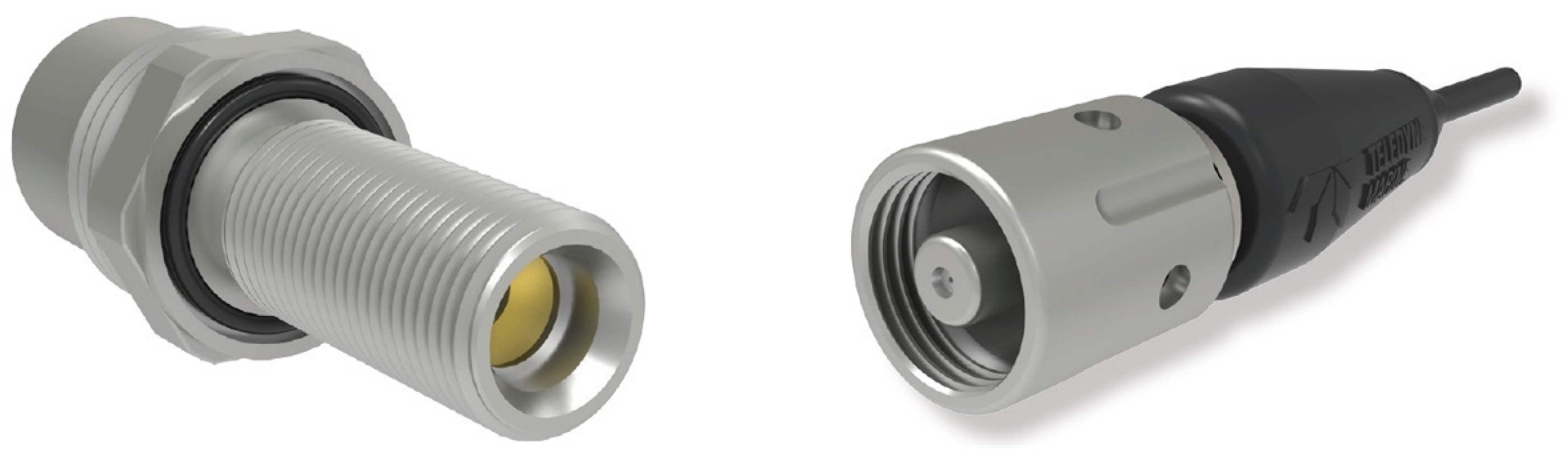
The Teledyne Marine Group is a leading-edge underwater technology company. In 2009, Teledyne Marine acquired ODI, an old brand of underwater systems, which became Teledyne ODI. The NautilusTM WM1.7-30 (Figure 5) is a famous electrical WMC of Teledyne ODI, which took the design of the PBOF and shuttle pins with wiping action. The Angled Physical Contact Rolling Seal Hybrid (APC-RSH) of Teledyne ODI is an advanced optical WMC, which employs the rolling seal design and APC technology. Teledyne ODI also combined the advantages of NautilusTM and APC-RSH to develop the NautilusTM Rolling Seal Hybrid Connector (NRH) (Figure 6). Furthermore, Teledyne Marine also has its own brand of underwater connectors: Impulse. The Optical 12,000 Meter Connector of Impulse-PDM (Figure 7) has been qualified for FOD operation, but it belongs to DMCs.
2.4. Functional Units
Underwater connectors have a very complicated structure, and it contains many precise and tiny parts. In order to help readers understand better and even facilitate design, the authors proposed the concept of functional units of underwater connectors, which refers to a certain portion of the structure that performs a specific function. This is not a specific structure of underwater connectors, but an abstract concept. Because some specific structures may undertake multiple functions, each functional unit is not independent but inseparable.
The functional units of underwater connectors can be categorized into connecting unit, sealing unit, pressure-balanced unit, aligning unit and locking unit. The definitions of them are as follows:
- (1)
- Connecting Unit provides the reliable and stable transmission of electricity or optical signal (or both) between plug and receptacle connectors with the desired specifications, when underwater connectors are in the mating state. The connecting unit is the primary functional unit, whose design is demanded not only to guarantee the stability and security of connections but also to reduce power loss on contact interfaces as much as possible.
- (2)
- Sealing Unit can provide enough water sealing performance for the underwater connectors. The sealing unit could be the most important functional unit, which should maintain a clean, stable and safe environment to the connecting unit. The sealing unit should prevent seawater, sediment, grit and any other contaminants from entering the interior of connectors, and prevent the oil leakage of PBOF connectors as well.
- (3)
- Pressure-Balanced (or Pressure-Compensated) Unit can produce an internal pressure to balance the ambient pressure automatically, reduce or even eliminate the differential pressure between the internal and the external of underwater connectors. An excellent pressure-balanced unit should have good reliability and sensitivity.
- (4)
- Aligning Unit aligns the electrical and optical connection to improve the quality of connection by its mechanical structure. It is an important functional unit to realize low power loss of underwater connectors, especially for optical connectors.
- (5)
- Locking Unit locks plug and receptacle connectors to improve reliability, stability and quality of connection after mating. The locking unit should be flexible to mate or de-mate the connectors.
It is necessary to emphasize again that all the above functional units are not independent; thus, the structural relationship between each of them must be fully considered in their design. The key technologies of each functional unit are discussed next.
3. Connecting Unit
3.1. Contact Resistance
The electrical connection of underwater connectors mainly depends on physical contact between two conductors directly. The design of the connecting unit must consider the theory of electrical contact that was developed by Ragnar Holm [42]. As there are many influencing factors, a unified model to describe the complex process occurring in the electrical contact area is still lacking today [20,43].
Electrical contact can be defined as an interface between two contact conductors, which guarantees the continuity of the electric circuit. However, the real contact surface is rough with many asperities that can penetrate the oxidation films and other contaminant films on the surfaces of conductors; therefore, localized contact areas are established. With the action of loads, the contact spots, termed a-spots in tribology, form the only conducting path of electrical contact. As a consequence, the current that passes through the contact interface, is constricted at the regions of the a-spots. This phenomenon increases the resistance in electrical contact, which is called constriction resistance Rc. If the a-spots are treated as circular, the total constriction resistance Rc in Ω of two contact conductors is [20,43]
where ρ1, ρ2 (Ω·mm) are the resistivities of two contact conductors, respectively; a (mm) is the radius of a circular a-spot.
Figure 8 depicts the current flow that passes through the electrical contact interface of the ideal and the real surface of two cylindrical conductors with the same radii. The constriction resistance Rc can be calculated from Laplace’s Equation with corresponding boundary conditions. An approximate solution was given by Timist first, and an exact solution was derived by Rosenfeld and Timist, shown as Equation (2) [44].
where R (mm) is the radius of the cylinder conductor.
Moreover, the surface of the conductors is not usually clean. Resistance increases because of the existence of contaminant films (e.g., thin oxidation films, sulfide films, inorganic films, etc.), which is called film resistance Rf [20,43]. The calculation of film resistance is very difficult, and the accurate numerical results can be obtained by using ANSYS Maxwell 2D or 3D simulations [45]. Consequently, the contact resistance Rcontact of electrical contact can be determined by [20,43].
What should be noted is that all the above discussions are based on the condition of direct current (DC). The contact resistance, affected by many factors, is one of the most important specifications of underwater electrical connectors. The value of per contact of main available COTS products is usually less than 0.01 Ω. The way of reducing contact resistance generally includes controlling surface finishing, using soft plating materials on the conductors, using pins and sockets with a wiping action, and so on [46,47,48,49]. The detailed discussion about contact resistance can be found in related book references [20,43], and the effects of alternating current (AC) can be found in the review paper of Rémouit et al. [19].
3.2. Electrical Insulation
Due to the electrical conductivity of seawater, electrical insulation is an essential issue for underwater electrical connectors [19]. Choosing the proper material is the primary task, and of course, reliable sealing design is also a key factor. A commonly used insulating material is epoxy resin that covers the outer surface of the conductor by injection molding. Other suitable plastics are also used in the same way [21]. Another choice is to use rubber as the insulating material directly. The conductors are covered by a rubber layer and fixed to the vulcanized rubber support [21]. This design can play a dual role of insulation and sealing.
In recent years, poly-ether-ether-ketone (PEEK) is widely used in the insulation of underwater connectors. PEEK was invented by Imperial Chemical Industries (ICI) in 1977. It has higher strength than ordinary plastic and can be machined by computer numerical control (CNC). Besides, PEEK has good insulation even under high-pressure and high-humidity conditions. Moreover, PEEK is self-lubricating with excellent fatigue resistance [21]. However, its high price limits its application.
An insulation design with inspiration concerns a micron insulation coating of polymeric-film, such a coating can be generated by physical vapor deposition (PVD) [48]. The coating material can be Teflon or Parylene. With wear-resistance, Teflon can be used in sliding insulation while Parylene can only be used in static insulation. Generally, such coatings as thin as 1 μm provide adequate electrical insulation of about 100~200 V [48], and coatings with the thickness of about 25 μm can meet the requirements of most underwater electrical connectors. The application of an insulation coating promotes the development of miniaturization and lightweight electrical connectors, which can increase the creepage distance and reduce the radial size of electrical connectors with multipins. The cost of the insulation coating is not very high, particularly in mass production, and the suitable PVD equipment is usually cheap. Insulation coating has a wide application prospect in the field of underwater connectors.
3.3. Coupling of Fiber-to-Fiber
Compared to the electrical connection, it is much more difficult to connect the light between two optical fibers together [50]. In the application of underwater connectors, the optical fibers that are commonly used are the single-mode fibers, which are the main concern of this paper. The two main types of optical connection in underwater connectors are called butt-jointing and expanded-beam [51].
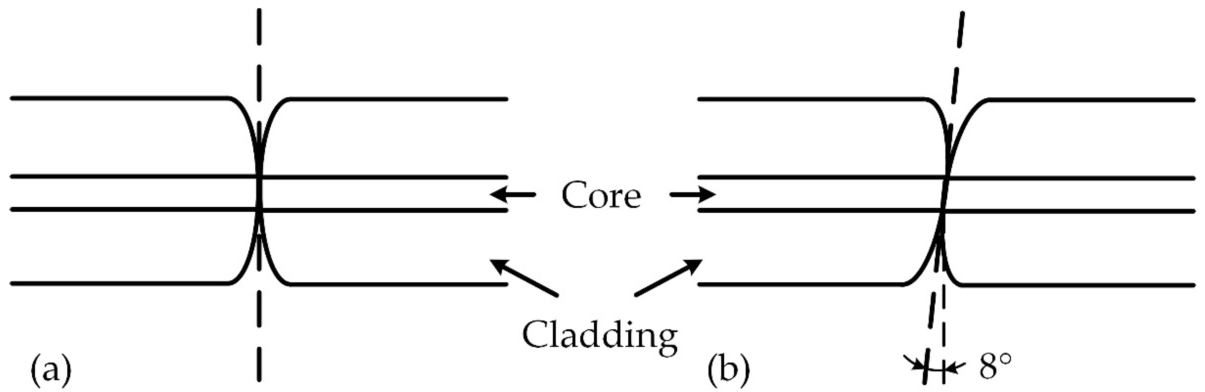
The butt-jointing type means that two optical fibers are connected directly by physical contacts of their end-faces. The finishing of physical contacts can be divided into UPC and APC (Figure 9), which are commonly used in ordinary optical connectors. The fiber end-faces of UPC connectors are processed into a slightly convex shape, so that they can conduce to eliminate the air-gap in the optical interface, while the fiber of APC connectors have angled end-faces, which can greatly improve performance with respect to reflectance loss [52]. The standard APC angle used in single-mode optical fibers of APC connectors is about 8° [50].
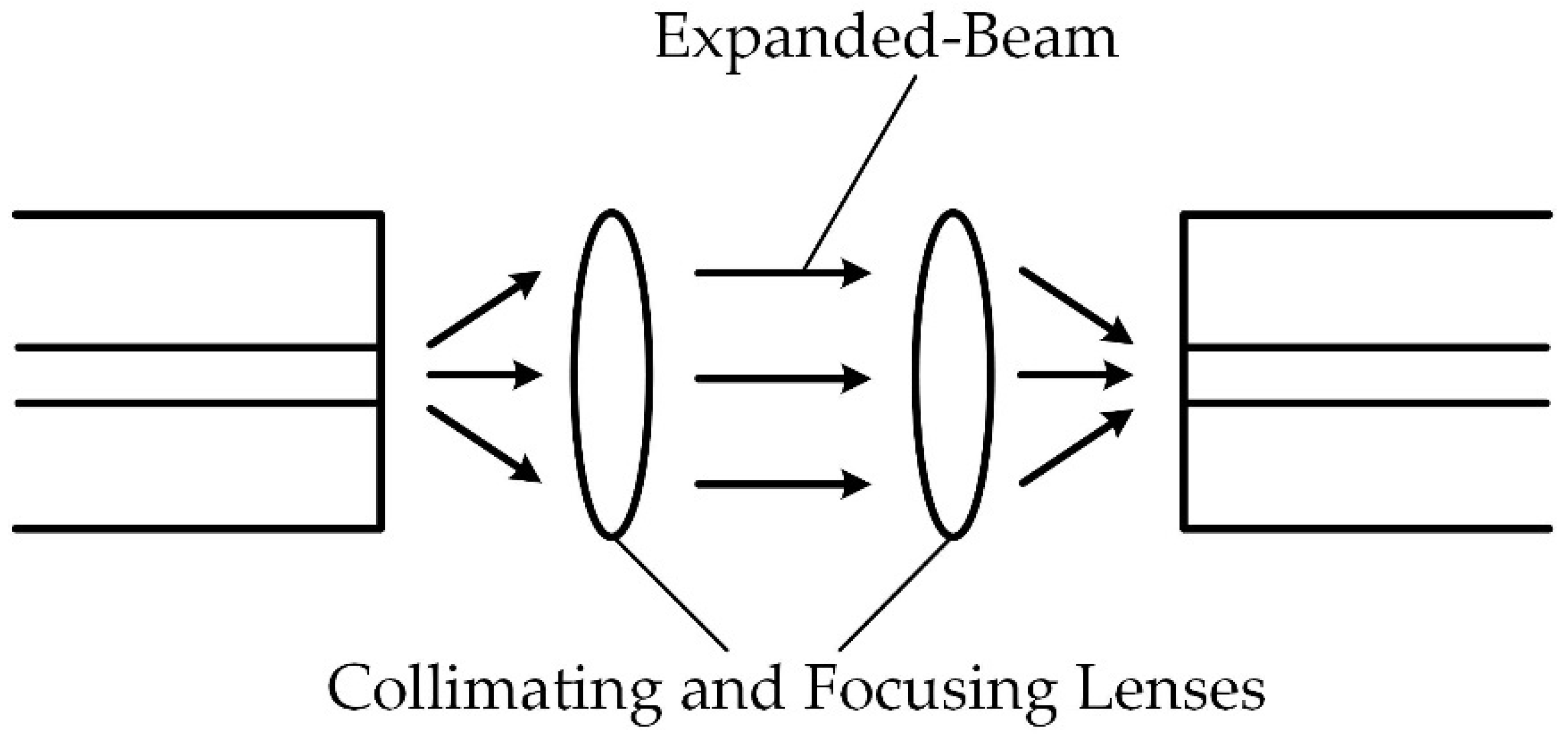
The expanded-beam type uses an optical (collimating and focusing) lens to assist in connecting the light between two optical fibers (Figure 10). The diffused light from one fiber can be collimated into a parallel extended beam via a collimating lens. Then, the extended beam goes through a focusing lens and can be refocused on the other fiber to complete the optical connection [51,53,54,55]. The commonly used lenses include thin lens, spherical lens, graded refractive index (GRIN) lens, aspheric lens and so on [50,56,57,58,59,60,61]. Cairns applied the quarter-pitch GRIN lens with glass caps (or sealing windows) to filter the selected portion of the infrared spectrum, which could improve the performance of optical connectors [54,62,63]. Compared with the butt-jointing type, the expanded-beam connectors have the following advantages:
- (1)
- The introduction of optical elements could not be affected by the offset and the end-gap between the end-faces of two optical fibers;
- (2)
- (3)
- The expanded-beam connectors are convenient for cleaning and assembling, and even easier for the integration of optical processing elements to achieve wavelength-division multiplexing, beam-splitting, switching and so on [55].
Due to the aberration of optical elements, the power loss of expanded-beam connectors is usually higher than that of butt-jointing connectors. That is why the butt-jointing type forms the majority among optical connectors. However, the expanded-beam type can still achieve low power loss, and with the advancement in lenses and the anticipation in the optical processing of signals, the study of expanded-beam connectors is of great significance [55].
3.4. Insertion Loss
Insertion loss (or coupling loss) Γinsertion is one of the significant specifications of underwater optical connectors, which can be defined by [50]
where η (%) is the optical connection efficiency or coupling efficiency; Pi (W) is the input power of the underwater connector system; Po (W) is the output power of the underwater connector system. The unit of insertion loss is the decibel (dB), and a connection efficiency of 89% corresponding to an insertion loss of 0.5 dB is a criterion of low-loss optical connectors [55].
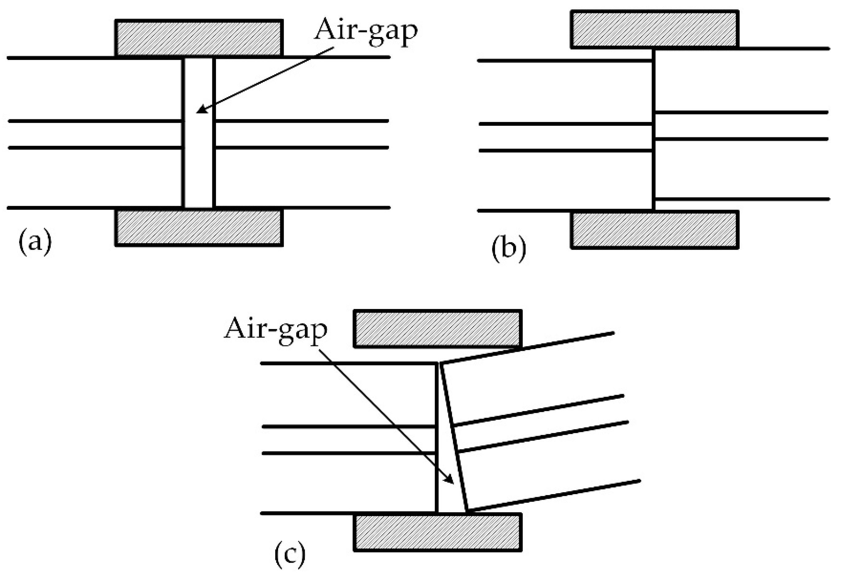
The major reason for power loss in optical connections is generally due to the offset of two optical fibers, which can be divided into transverse offset, longitudinal offset and angular offset (Figure 11). The air-gap could be the result of transverse offset which has the most significant influence on insertion loss among these three categories [51,65,66,67,68]. Besides, the concentricity of two optical fibers is dependent on longitudinal offset, and angular offset or tilt would also result in an air-gap on the optical interface, from which arises Fresnel reflection. This kind of air-to-glass interface has about 0.31 dB insertion loss. The tiny air-gap could also result in multiple reflections with a higher 0.7 dB insertion loss [69]. The ideal butt-jointing design could eliminate Fresnel reflection, but the damage of optical fibers because of mating and de-mating could still produce reflection. Thus, the commonly practice is to fill with index-matching medium (e.g., gel or fluid, etc.) into the optical interface [64,67,70,71,72]. Moreover, the antireflective coating can also be used on the end-faces of two optical fibers to reduce insertion loss effectively [62]. What is more, the end-face quality of the optical fibers, which should be controlled by polishing procedures to produce the desired flatness and surface finish, is another important influencing factor of insertion loss [51]. Generally, for low-loss connectors, the surface finish is 0.025 μm without the index-matching medium, and is 0.18 μm with it [55].
3.5. Return Loss
The reflection on the optical interface of two connected fibers will result in back reflection of light, causing light power loss, and this is called return loss Γreturn which can be defined by [50]
where ηf (%) is the optical reflection efficiency; Pr (W) is the reflection power of the underwater connector system. The unit of return loss is also the decibel (dB), and a reflection efficiency of 1‰ corresponds to a return loss of 30 dB [50]. The methods to reduce the power loss of reflection, or to increase return loss, include using the index-matching medium filled into the optical interface and using the technologies of UPC and APC. The return loss of index-matching connectors can reach 25 to 30 dB [55], and that of UPC connectors can be 40 dB. As for APC connectors, return loss will be up to 60 dB [50].
Here, what is worth mentioning is that the above-mentioned issues of misalignment and losses are very different in underwater conditions compared to terrestrial conditions. As we know, the refractive index of water is about 1.33, which increases with the increase of salinity under the sea [3]. It is much closer to the refractive index of optical fibers (about 1.45) compared with that of air. Thus, if seawater enters the interface of an optical connection, the reflection-induced losses will be reduced, especially in expanded-beam type connectors. Accordingly, some designs allow seawater to enter the optical interface between the collimating and focusing lenses, and the trapped water provides an index-matching medium to improve the performance of the optical coupling [54]. As will be introduced in the next section, the index-matching dielectric fluid closer to that of seawater, is widely used in PBOF connectors to provide better optical performance.
4. Sealing Unit and Pressure-Balanced Unit
4.1. Sealing Unit
The sealing design of underwater connectors is undoubtedly a great challenge, which makes the sealing unit become the most important functioning unit. For DMCs, rubber is directly molded into the body of a connector by vulcanization, that is RM connectors. It can perform the functions of water tightness and pressure-resistance. Generally, with a rigid body, BH connectors can be used in a depth of 7000 m. The main problem is how to prevent the deformation and the degradation of rubber [21], and this is related to the material compounds that are usually the secrets of manufacturers. The commonly used O-rings are also widely used in underwater connectors, which can be attached to the pressure housing of the rigid-shell of BH connectors [24]. Today, there are a lot of codes and standards of O-rings, and there are also numerous handbooks from their manufacturers [73]. Even so, the design of the O-ring static sealing is extremely important. The world-shaking dramatic destruction of the NASA space shuttle Challenger in 1986 was attributed to a static O-ring that cost seven humans their lives [74].
For the WMCs, the situation is quite different. In order to achieve wet-mating under the sea, especially in a deep-sea environment, it must eliminate the differential pressure between the inside and outside of connectors or at least reduce it to a minimum. Thus, PBOF technology, which is described next, is widely used in top WMCs. The benefits from PBOF technology, and the difficulty in designing a sealing unit is greatly reduced. Remember that the sealing designs of PBOF connectors are all based on the principle that the pressure differential between the inside and outside of the connectors is very small. For the static sealing design of WMCs, the ordinary O-ring design is generally enough. The key issue becomes the dynamic sealing design, because the seal failure of WMCs is mainly due to the mating and de-mating operation in engineering experiences, which will be illustrated later. Although the dynamic sealing performance in hydraulic systems has been basically understood, as reviewed by [75], it is still very important to study the dynamic sealing of PBOF connectors because of the different boundary conditions [27]. What is worth mentioning is that the theory of elastic hydrodynamic lubrication (EHL) can be used in the above analysis, as found by Dowson and Higginson [76]. The EHL theory is a powerful tool that can be used not only in the study of dynamic sealing [77,78], but also in the lubrication analysis of any kind of novel gear mechanisms [79]. Thus, the numerical model should consider the hyperelasticity of rubber materials, Reynolds equation, contact mechanics, tribology, and so on [27,78].
4.2. PBOF Technology
As was previously mentioned, to realize mating and de-mating under the sea, the differential pressure between the inside and outside of the connectors must be eliminated or reduced to a minimum. Otherwise, huge pressure will lead to a tremendous mate/de-mate force, which will make the wet-mating impossible. This is what a pressure-balanced unit means. The basic principle of pressure balanced is very simple. According to Pascal’s Law, fluid has such properties as incompressibility and uniform transfer of pressure. Thus, if we can introduce the seawater into a pressure-compensated element that is immersed into the filled fluid of the interior chamber of underwater connectors, the ocean pressure will be transferred to the interior of the rigid-shell of connectors by the filling fluid. Therefore, the differential of inner and outer pressure can be reduced and even eliminated.
For the filling fluid, engineers used dielectric viscous semi-mobile compounds (e.g., gel, silicone grease, etc.) from the beginning, which can also eliminate air-pockets and arcing [80,81]. However, the contaminants having entered are easier to form conductive paths. Then, the filled medium is substituted by dielectric oil gradually, which can improve the electrical degradation [82]. Thus, the dielectric oil, especially silicon oil today, becomes the most popular filling medium in WMCs, and that is why we often call this method PBOF technology. A commonly used filling oil is XIAMETER PMX-200 Silicone Fluid (previously known as DC 200) that is produced by Dow Corning. Its refractive index can be up to 1.4 [83], which is an ideal filling oil for optical WMCs.
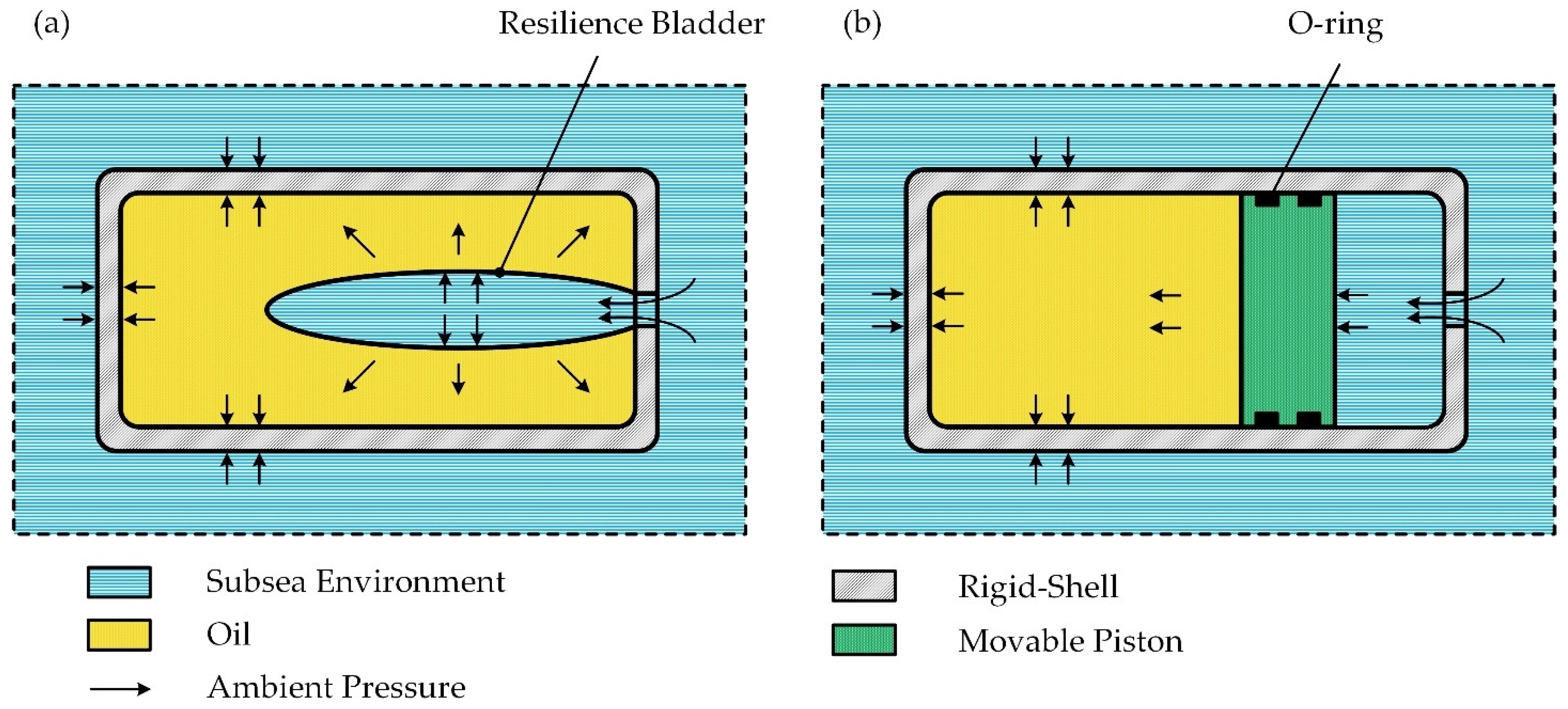
Pressure-balanced elements are the essential components of WMCs, which directly affect the performance of a pressure-balanced unit. There are mainly two types of pressure-balanced element, which are the resilience bladder and the movable piston. The mechanisms of the two kinds of pressure-balanced unit are illustrated simply in Figure 12, and we can also understand the mechanism of PBOF technology in Figure 12. The movable-piston type has a complex structure with lower sensitivity and reliability, while the resilience-bladder type has a simple structure and an immediate response to any pressure change of the outer environment without substantial force or friction. The resilience-bladder type is widely used in top WMCs. However, it is very difficult to produce, and it may be the most expensive component of WMCs. The resilience bladder can be made of fluoro-silicone rubber (even with a layer of special woven fabric to enhance strength) by molding, and the molds are generally customized to produce a variety of bladders.
Moreover, it is worth mentioning that there seems to be no literature to reveal how to calculate the differential pressure in a pressure-balanced unit. The Reference [27] says that this differential pressure is usually smaller than 0.5% of water pressure, but there is no citation or other details. This problem is very important because it is related to how to design such a bladder. This may involve some confidential technologies of the manufacturers of WMCs, which is one of the reasons why WMCs have easily become a bottle-neck product. The authors are devoted to the work in this area, and it has come to the experimental verification stage at the moment.
4.3. Penetrable Self-Sealing
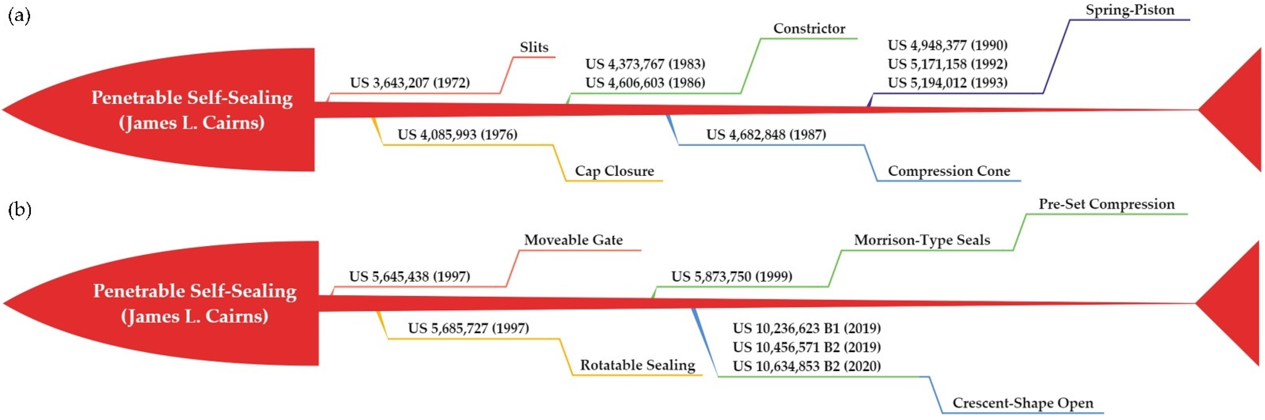
Another serious issue for WMCs is how to maintain the sealing performance in the dynamic process of mating and de-mating. Even with PBOF technology, it is still a tough task. James L. Cairns, one of the most famous inventors in the field of WMCs, seems to have devoted his whole life to seeking a satisfactory design for penetrable self-sealing. At first, the idea was very simple, that is, to make a slit in a rubber seal which could be passed by a blade-type pin [49,80]. However, only depending on the resilience of the rubber itself to make the slit close, usually caused failure. Then, Cairns designed many kinds of accessory component to assist the slit to close promptly, which made the structure very complex [63,82,84]. The successful application for the design in this field is called the lip seal.
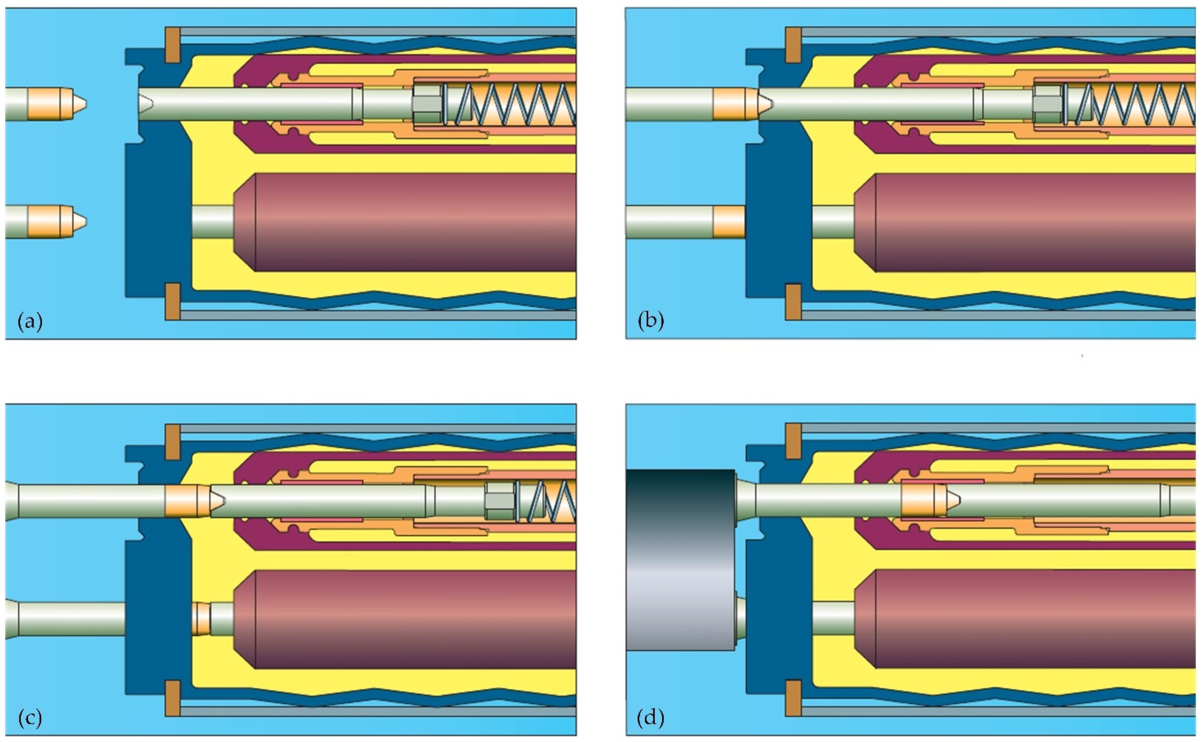
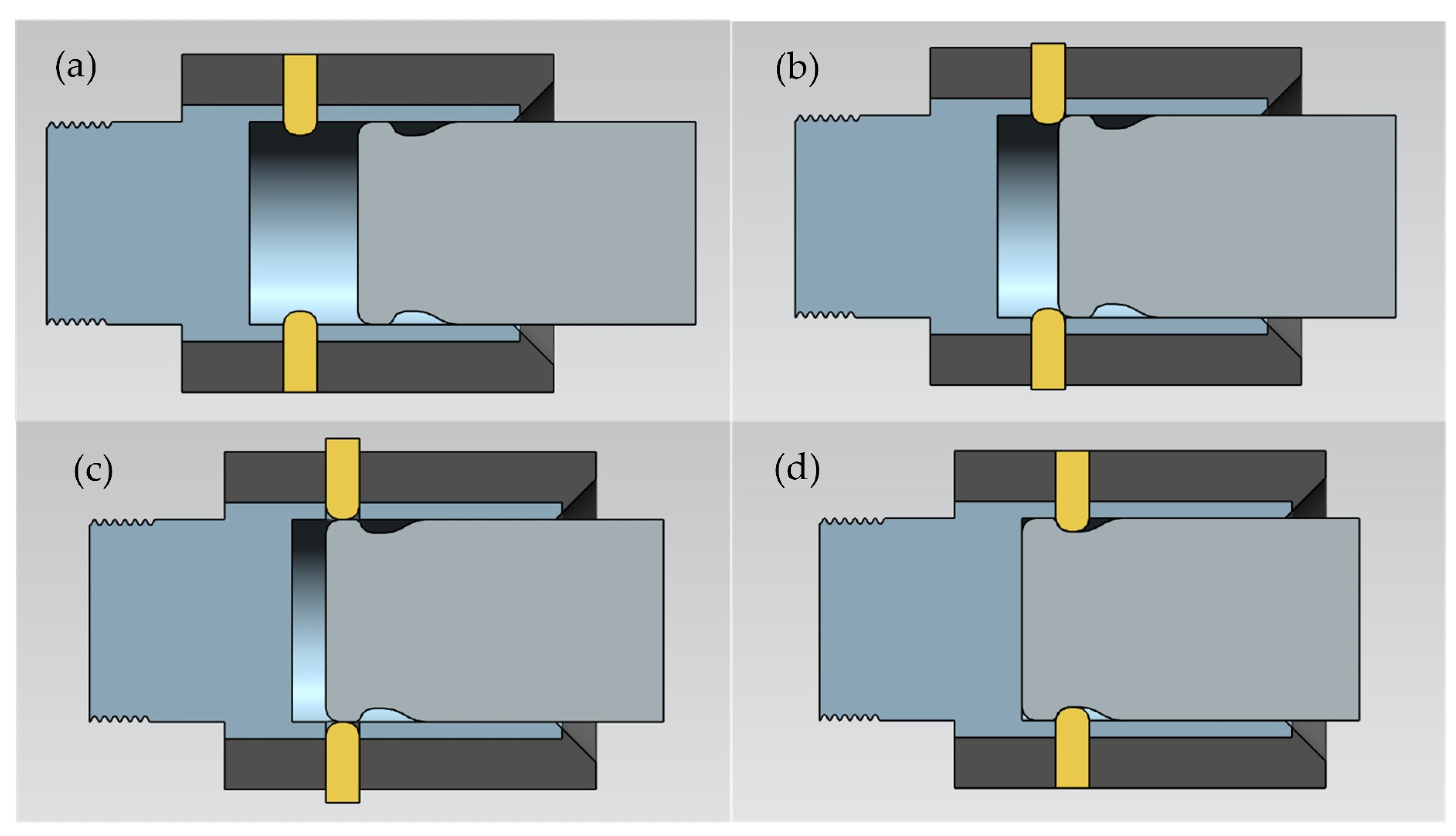
In the early 1990s, a great invention came out, which is called the shuttle pin design [48,85,86,87,88]. As is depicted in Figure 13, a movable dielectric stopper extends through the passageway formed in the end seal. As the pin is inserted into the end seal, it pushes the stopper into a retracted position. When the pin is withdrawn, the stopper always follows the pin due to the restoring force of a spring. In fact, it is also a variant of the lip seal, which uses the stopper-spring type to eliminate the accessory components that assist in closing the slit. The shuttle pin design was a brilliant success, and was soon widely used in products of various brands, such as the SEACON HydraElectric, Teledyne ODI NautilusTM, Siemens DigiTRON and so on. The only fatal drawback is that it can only be used for electrical WMCs, and the plug connector must be disconnected from the power when mating or de-mating.
In the late 1990s, Cairns invented a completely new design to address the issue of optical connections, which is called the rolling seal. It was widely used in both electrical and optical WMCs of Teledyne ODI. The rolling seal design mainly includes a rotatable gate with passageways. In the de-mating state, the gate is closed, but when the plug connector is inserted into the receptacle connectors, the gate will gradually rotate to the open position [70,90,91]. It is an ingenious idea, but it is extraordinarily difficult to achieve this function. Even if a small detail goes wrong, the whole seal will lose efficacy. As a result, the rolling seal design became the unique technology of ODI.
When the story comes here, almost all the technical problems about WMCs can be solved by the above-mentioned design. However, Cairns did not seem to be content with that. An ideal penetrable seal-sealing should be like the original idea, namely, there is a precut in a rubber seal, and whether a pin is inserted into it or withdrawn, the seal can always keep watertight. In 2019, Cairns made a crescent-shaped opening in a rubber seal, and the result of the experiment shows that this design can seal a pressure of about 0.24 MPa [92,93,94]. With PBOF technology, it may be used in WMCs at a depth of 4000 m. The technology evolution map of the above-mentioned designs is shown in Figure 14, but an effective penetrable self-sealing with a simple structure is still on the way.
5. Aligning Unit and Locking Unit
The core radius of single-mode optical fibers is less than 10 μm. The prior study shows that if the transverse offset is more than 10% of the fiber core radius, the insertion loss of optical connectors could be more than 0.3 dB [53]. Thus, the low-loss underwater optical connectors require submicron accurate alignment [55]. In this case, the aligning unit is essential to ensure the reliability and stability of the connection in a harsh environment. For optical connectors, the aligning unit is the key to achieving low insertion loss [51].
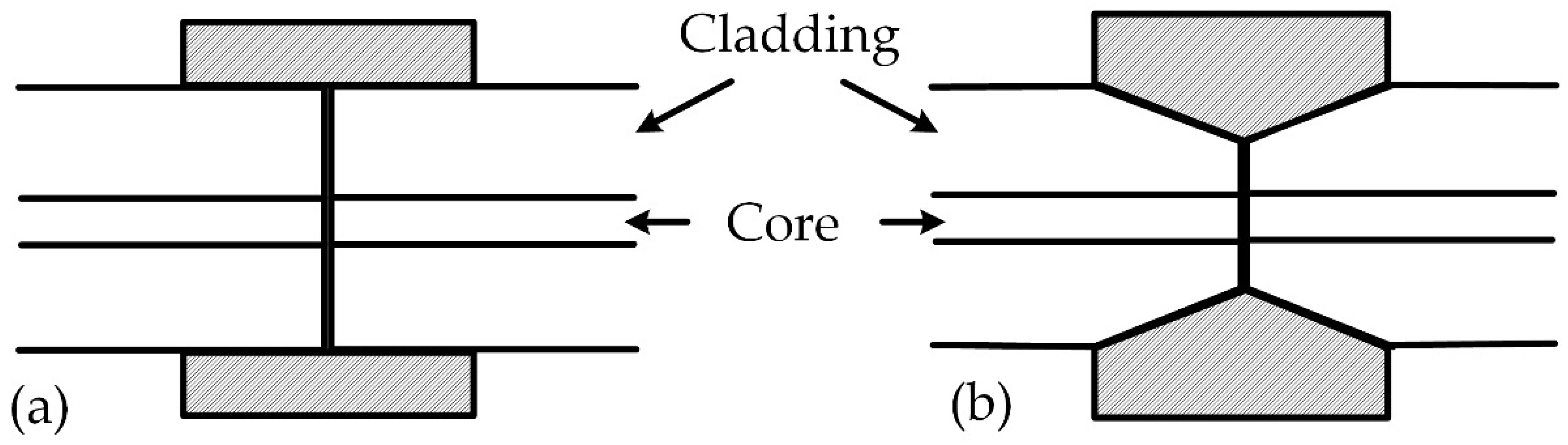
According to the discussion in Section 3, the butt-jointing connectors are easily affected by transverse offset, while the expanded-beam connectors are easily affected by angular offset. Therefore, the design of aligning units of underwater optical connectors can be considered as a trade-off of either controlling later offset or controlling angular offset [55]. Fortunately, the aligning design of non-underwater solutions is still valid for underwater applications nowadays. Two examples of popular aligning units used in underwater connectors are depicted in Figure 15. Other geometries used for alignment include V-grooves, rods, and so on [51,63].
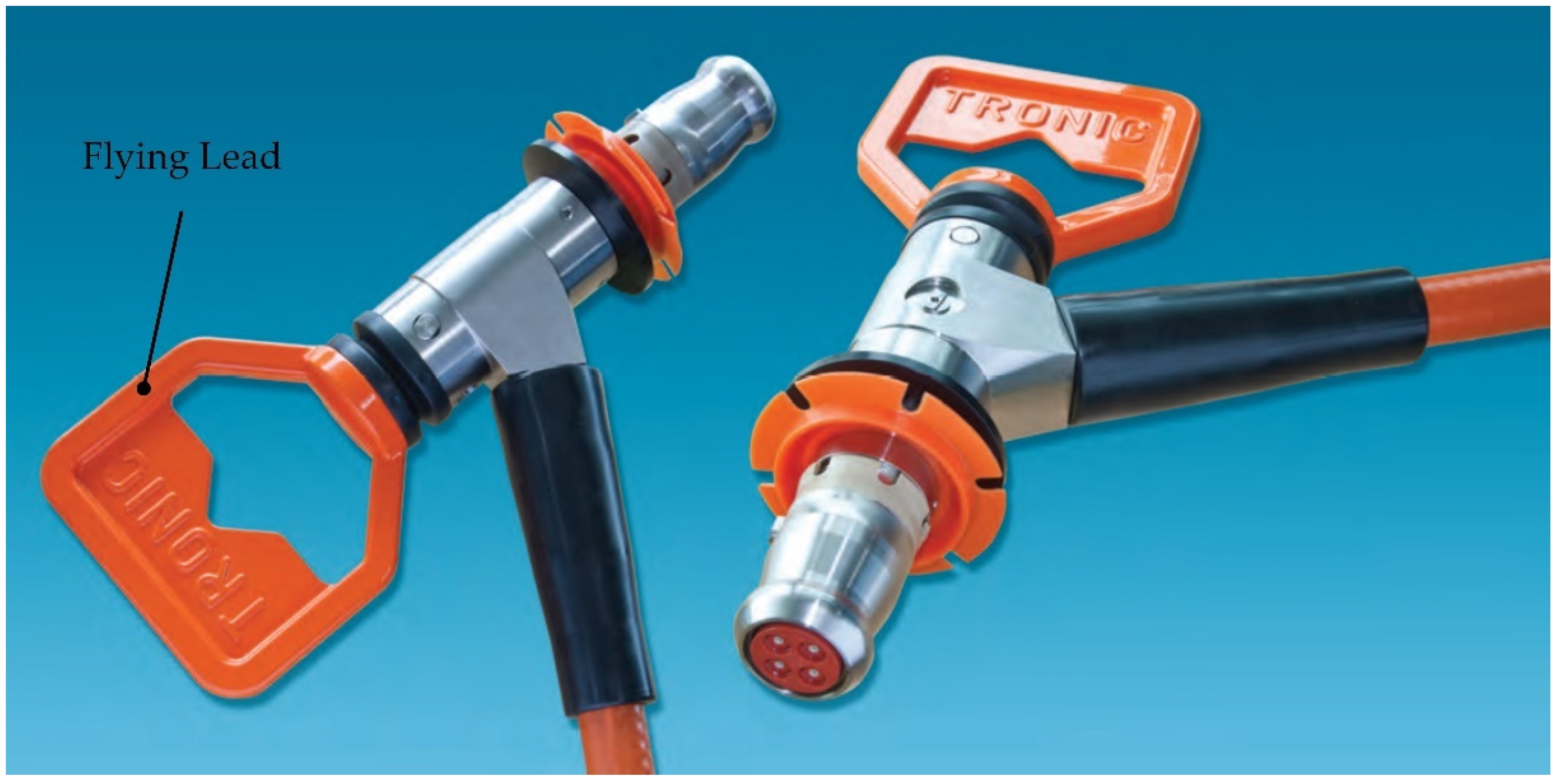
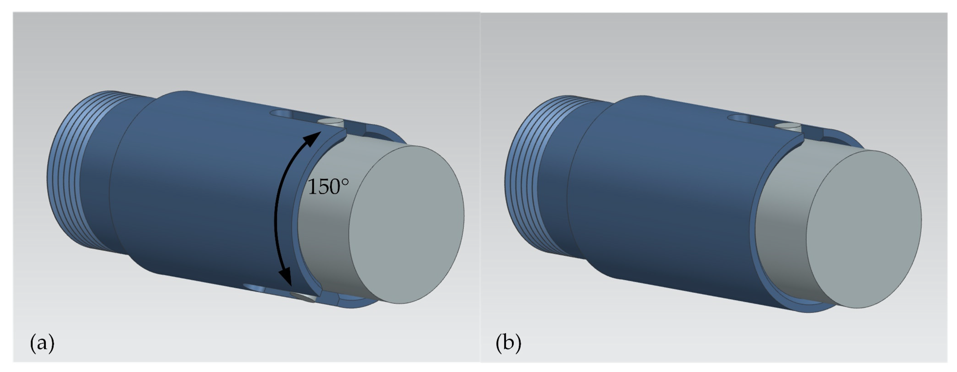
The locking unit is also an important functional unit, which can be achieved by locking mechanisms. To lock connectors underwater seems a real nightmare, but this problem is actually related to the application field and depth of the environment. For DMCs, the locking operation after mating can be completed by the screw thread. For the WMCs used in a shallow-water area, the screw thread is also an effective way, and the operation can be completed by divers. However, for the WMCs used in deep-sea, the mating or de-mating operation can only be completed by manipulators in ROVs. Thus, the threaded connection is no longer available, so it must be replaced by a latching mechanism, which is depicted in Figure 16. The clever latching mechanism has the function of automatic locking when the engagement occurs, and it can also automatically unlock when connectors are de-mated. To cooperate with the operation of an ROV, these WMCs are equipped with the flying leads for the manipulators to grasp, which are shown in Figure 17.
Moreover, the aligning unit and locking unit are always closely tied. In the actual mechanical design, one specific structure can perform the functions of both aligning and locking. The key and keyway are one of the most popular designs in optical WMCs, especially in UPC connectors and APC connectors, which are shown in Figure 18.
6. Discussions and Conclusions
6.1. Discussions
Underwater connectors are essential components of marine equipment, which have their own global market. WMCs represent the highest level of technology in this field, and the market is monopolized by several companies around the world. Due to the technical blockage from several developed countries, WMCs have become one of bottleneck techniques for China. The design of underwater connectors is truly a multidisciplinary art, including electromagnetics, optics, mechanical engineering, electrical engineering, material science, tribology and so on. However, the key technologies of underwater connectors are mostly confidential commercial information. Even with a history of 70 years, there have been relatively few research papers on this topic published. Therefore, underwater connectors could be a constraining factor to some nations.
Underwater connectors can draw on many general techniques for ordinary connectors, rubber materials, deep-sea equipment and so on. For DMCs, low-end products, such as those of Subconn® Circular, are mainly RM connectors. Because the process technology of rubber molding is very mature, the key technology about RM connectors is mainly down to the rubber material itself. Some small businesses in China have been able to manufacture DMCs of good quality, and sell them abroad, such as in Russia. Nowadays, even the DMCs used in the environment of FOD pressure are not a problem for China. However, for WMCs, they are still monopolized by a very few countries, so that is why this paper mainly focuses on them.
PBOF technology is indispensable for WMCs. It is not limited to reducing the differential pressure of WMCs, it also virtually improves the pressure-resistance of the connectors. This is of great significance for deep-sea equipment, and the pressure-compensation device is a good example, which is widely used in deep-sea submersibles to protect the expensive electronic elements, batteries and any other component with low pressure-resistance. These pressure-compensation devices are also monopolized by a very small number of countries. Another application scenario of PBOF connectors is about DOSs. Imagine that, if we want to develop a DOS with a working pressure of 200 MPa, there are scarcely any connectors that can be used under the conditions of such high pressure, but PBOF connectors could solve this issue, even though wet-mating is not required in DOSs.
The penetrable self-sealing is another valuable research area, and an effective and simple design still needs genius inspiration. The penetrable self-sealing can be developed into a general technology. For instance, medical devices (e.g., optical or electrical probes, miniature surgical tools, etc.), must often be inserted into or removed from a patient [93]. Thus, a penetrable sealed connection is required.
Finally, the failure of a connector mainly occurs due to material degradation, sealing failure or an inadequate use for the environment [19]. Lamare and Vernin gave the feedback of the WMCs used in ANTARES, and they found that the failure of connectors is most likely after mating or de-mating [18], and sea water entering the oil-filled chamber is another common problem. The reliability study of underwater connectors can be done by using failure mode effect and criticality analysis (FMECA), which allows the possible failure of connections to be evaluated [19]. Anyhow, underwater connectors, especially WMCs, are very precise components. Any tiny failure of any function unit can lead to the failure of the connectors, and then the total failure of the whole system may happen. That is why the authors emphasized that all the functional units are not independent, and the structural relationship between each of them must be fully considered in the design by engineers.
6.2. Conclusions
An overview on the state-of-the-art of underwater connectors, both electrical and optical, is carried out in this paper. Several of the main available COTS connectors were introduced in detail. From the perspective of structure and function, the abstract concept of functional units has been proposed, which could be helpful to better understand and design underwater connectors. Five major functional units were categorized into connecting units, sealing units, pressure-balanced units, aligning units and locking units.
The connecting unit is the primary functional unit to realize the basic functions of connectors with specifications (e.g., contact resistance, insulation resistance, insertion loss, return loss, etc.). The theory of electrical contact and optics should be considered in the design of electrical and optical connection, respectively. Electrical insulation is an essential issue for underwater electrical connectors, and the application of PEEK and a micron insulation coating of polymeric film are very inspiring. There are two fiber-to-fiber connection types: butt-jointing and expanded-beam. Each of them has their own advantages and disadvantages with a lot of inspiring ideas. Furthermore, the technologies of UPC and APC are significant to the butt-jointing type of optical connection.
The sealing unit is the most important functional unit. Rubber is the most common and important material for underwater connectors. The rubber itself can also have a wiping function for WMCs, which can help to clean the contaminants during mating and de-mating. PBOF technology is widely applied in the first-class products of WMCs worldwide, which can eliminate or reduce the differential pressure and enhance the pressure-resistance of connectors. The resilience-bladder type is widely used in top WMCs. However, it is very difficult to produce, and it may be the most expensive components of WMC. The technology evolution of penetrable self-sealing is illustrated in detail, and the related research is of great significance.
The aligning unit and locking unit are also important to underwater connectors, which are the key to achieve low loss of connection, especially to optical connectors. There are various mechanical designs of aligning and locking structures in underwater connectors, which can also be improved and developed innovatively in the future.
The rapid development of deep-ocean technology needs more underwater connectors with high performance. Traditional underwater connectors are always essential and fundamental, and any maritime power needs to make efforts to achieve breakthroughs. Furthermore, engineers also need to focus on related advanced and multidisciplinary theories in the future. Incorporating them into the development of underwater connectors will promote the accelerated development of deep-ocean technology systems.
Author Contributions
Conceptualization, W.S. and W.C.; methodology, W.S. and W.C.; software, W.S.; validation, W.C.; formal analysis, W.S.; investigation, W.S.; resources, W.S. and W.C.; data curation, W.S. and W.C.; writing—original draft preparation, W.S.; writing—review and editing, W.S. and W.C.; visualization, W.S.; supervision, W.C.; project administration, W.C.; funding acquisition, W.C. Both authors have read and agreed to the published version of the manuscript.
Funding
This work was supported by Zhejiang Key R&D Program (Grant No. 2021C03157), the “Construction of a Leading Innovation Team” project by the Hangzhou Municipal government, the startup funding of New-Joined PI of Westlake University with grant number (041030150118) and the funding support from the Westlake University and Bright Dream Joint Institute for Intelligent Robotics.
Institutional Review Board Statement
Not applicable.
Informed Consent Statement
Not applicable.
Data Availability Statement
The data used to support the findings of this study are available from the corresponding author upon request.
Acknowledgments
Critical comments from three anonymous reviewers are greatly appreciated and they are very helpful for improving the quality of the paper.
Conflicts of Interest
The authors declare no conflict of interest.
References
- Trujillo, A.P.; Thurman, H.V. Essentials of Oceanography, 12th ed.; Pearson: Boston, MA, USA, 2017; pp. 3–38. ISBN 978-013-407-354-5. [Google Scholar]
- How Much of the Ocean Have We Explored? Available online: https://oceanservice.noaa.gov/facts/exploration.html (accessed on 19 July 2021).
- Garrison, T.; Ellis, R. Oceanography—An Invitation to Marine Science, 9th ed.; Cengage Learning: Boston, MA, USA, 2016; pp. 165–196. ISBN 978-130-525-428-2. [Google Scholar]
- Song, W.T.; Cui, W.C. Review of deep-ocean high-pressure simulation systems. Mar. Technol. Soc. J. 2020, 54, 68–84. [Google Scholar] [CrossRef]
- Cui, W.C.; Guo, W.; Wang, F.; Jiang, Z.; Luo, G.S.; Pan, B.B. Technologies and Applications of Submersibles; Shanghai Scientific & Technical Publishers: Shanghai, China, 2018; pp. 1–12. ISBN 978-754-784-173-0. [Google Scholar]
- Cui, W.C.; Hu, Y.; Guo, W.; Pan, B.B.; Wang, F. A preliminary design of a movable laboratory for hadal trenches. Methods Oceanogr. 2014, 9, 1–16. [Google Scholar] [CrossRef]
- Vedachalam, N.; Ramesh, R.; Jyothi, V.B.N.; Prakash, V.D.; Ramadass, G.A. Autonomous underwater vehicles: Challenging developments and technological maturity towards strategic swarm robotics systems. Mar. Georesources Geotechnol. 2019, 37, 525–538. [Google Scholar] [CrossRef]
- Teague, J.; Allen, M.J.; Scott, T.B. The potential of low-cost ROV for use in deep-sea mineral, ore prospecting and monitoring. Ocean. Eng. 2018, 147, 333–339. [Google Scholar] [CrossRef]
- Wynn, R.B.; Huvenne, V.A.I.; Le, B.T.P.; Murton, B.J.; Connelly, D.P.; Bett, B.J.; Ruhl, H.A.; Morris, K.J.; Peakall, J.; Parsons, D.R.; et al. Autonomous underwater vehicles (AUVs): Their past, present and future contributions to the advancement of marine geoscience. Mar. Geol. 2014, 352, 451–468. [Google Scholar] [CrossRef] [Green Version]
- Cui, W.C. An overview of submersible research and development in China. J. Mar. Sci. Appl. 2018, 17, 459–470. [Google Scholar] [CrossRef]
- Cui, W.C. Development of the Jiaolong deep manned submersible. Mar. Technol. Soc. J. 2013, 47, 37–54. [Google Scholar] [CrossRef]
- Kohnen, W. Human exploration of the deep seas: Fifty years and the inspiration continues. Mar. Technol. Soc. J. 2009, 43, 42–62. [Google Scholar] [CrossRef]
- Moorhouse, P. A modern history of the manned submersible. Mar. Technol. Soc. J. 2015, 49, 65–78. [Google Scholar] [CrossRef]
- Bowen, A.D.; Yoerger, D.R.; Whitcomb, L.L.; Fornari, D.J. Exploring the deepest depths: Preliminary design of a novel light-tethered hybrid ROV for global science in extreme environments. Mar. Technol. Soc. J. 2004, 38, 92–101. [Google Scholar] [CrossRef]
- Lin, M.W.; Yang, C.J. Ocean observation technologies: A review. Chin. J. Mech. Eng. 2020, 33, 32. [Google Scholar] [CrossRef] [Green Version]
- Duennebier, F.K.; Harris, D.W.; Jolly, J.; Caplan-Auerbach, J.; Jordan, R.; Copson, D.; Stiffel, K.; Babinec, J.; Bosel, J. HUGO: The Hawaii undersea geo-observatory. IEEE J. Ocean. Eng. 2002, 27, 218–227. [Google Scholar] [CrossRef]
- Kalekin, O. The ANTARES underwater neutrino telescope. J. Phys. Conf. Ser. 2009, 160, 12036. [Google Scholar] [CrossRef]
- Lamare, P.; Vernin, P. Underwater mateable electro-optical connectors: The feedback from ANTARES. Nucl. Instrum. Methods Phys. Res. Sect. A: Accel. Spectrometers Detect. Assoc. Equip. 2009, 602, 252–254. [Google Scholar] [CrossRef]
- Rémouit, F.; Ruiz-Minguela, P.; Engström, J. Review of electrical connectors for underwater applications. IEEE J. Oceanic. Eng. 2018, 43, 1037–1047. [Google Scholar] [CrossRef] [Green Version]
- Slade, P.G. Electrical Contacts: Principles and Applications, 2nd ed.; Taylor & Francis Group: Oxford, UK, 2013; pp. 3–11, 231–373. ISBN 978-143-988-131-6. [Google Scholar]
- He, L.Y.; Li, Z.G. Theory and Application of Watertight Connectors; China Science Press: Beijing, China, 2020; pp. 29–87. ISBN 978-750-885-824-1. [Google Scholar]
- Hardy, K.; James, M. Pressure testing: Best practices. Mar. Technol. Soc. J. 2009, 43, 123–127. [Google Scholar] [CrossRef]
- Huang, H.C.; Shen, Y.; Yang, Z.G.; Zhao, H.Y.; Sheng, C.W.; Guo, Y.; Wei, Y. A deep-sea large-volume high-pressure simulation system—Design, analysis and experimental verification. Ocean Eng. 2019, 180, 29–39. [Google Scholar] [CrossRef]
- Christ, R.D.; Wernli, R.L. The ROV Manual, 2nd ed.; Butterworth-Heinemann: Oxford, UK, 2014; pp. 163–220. ISBN 978-008-098-288-5. [Google Scholar]
- Cairns, J.L. Recent advances in underwater mateable electrical connectors. In Proceedings of the OCEANS’83, San Francisco, CA, USA, 29 August–1 September 1983; pp. 507–511. [Google Scholar] [CrossRef]
- Cairns, J.L. Hybrid wet-mate connectors: “Writing the next chapter”. Sea Technol. 1997, 38, 17–22. [Google Scholar]
- Han, Q.; Chen, H.Y.; Yang, W.C.; Zhang, Y.; Yang, J.K.; Chen, Y.F. Analysis of reciprocating O-ring seal in the pressure-balanced oil-filled wet-mate electrical connectors for underwater applications. Lubr. Sci. 2019, 31, 335–345. [Google Scholar] [CrossRef]
- Jenkins, D.; Christiansen, M. Enabling technology: High capacity wet mateable optic connection. In Proceedings of the 2012 Oceans, Hampton Roads, VA, USA, 14–19 October 2012. [Google Scholar] [CrossRef]
- Seilhan, D.S.; Pepper, D.F. Miniature Underwater Connector. U.S. Patent 5,888,083, 30 March 1999. [Google Scholar]
- Baer, C.M.; Alten, M.; Bixler, G.; Fredette, L.; Owens, J.; Purvinis, G.; Schaefer, J.; Stout, G. Non-contact wet mateable connector. In Proceedings of the OCEANS 2009, Biloxi, MS, USA, 26–29 October 2009. [Google Scholar] [CrossRef]
- Bokenfohr, M.; Ciamulski, T. Underwater Connector Arrangement. U.S. Patent 10,355,334 B2, 16 July 2019. [Google Scholar]
- Centelles, D.; Rubino, E.; Soler, M.; Martí, J.V.; Sales, J.; Marin, R.; Sanz, P.J. Underwater radio frequency based localization and image transmission system, including specific compression techniques, for autonomous manipulation. In Proceedings of the OCEANS 2015—Genova, Genova, Italy, 18–21 May 2015. [Google Scholar] [CrossRef]
- Granger, R.P.; Baer, C.M.; Gabriel, N.H.; Labosky, J.J.; Galford, T.C. Non-contact wet mateable connectors for power and data transmission. In Proceedings of the 2013 OCEANS—San Diego, San Diego, CA, USA, 23–27 September 2013. [Google Scholar] [CrossRef]
- Shi, J.G.; Li, F.R.; Peng, S.L.; Cai, W.Y.; Pan, M.; Yu, H.B. Design and analysis of a noninsert wet mateable connector for underwater power and data transfer. Mar. Technol. Soc. J. 2020, 54, 65–78. [Google Scholar] [CrossRef]
- Shi, J.G.; Zhang, S.Y.; Yang, C.J. High frequency RF based non-contact underwater communication. In Proceedings of the 2012 Oceans—Yeosu, Yeosu, Korea, 21–24 May 2012. [Google Scholar] [CrossRef]
- Smith, D.; Clayson, A.; Taylor, R. Subsea Connection Assembly Provided with Inductive Elements for Data Transmissions. U.S. Patent 10,377,448 B2, 13 August 2019. [Google Scholar]
- Mulcahy, M. SEA CON: More than 40 years of underwater connector innovations. Sea Technol. 2009, 50, 21–26. [Google Scholar]
- Robust, Flexible and Reliable Fibre Optical Connector. Available online: https://www.macartney.com/what-we-offer/systems-and-products/connectors/optolink/optolink-fibre-optic-connector/ (accessed on 19 July 2021).
- Teledyne ODI Nautilus Connector. Available online: http://www.teledynemarine.com/Lists/Downloads/Nautilus%20WM1.7-30%20Datasheet.pdf (accessed on 19 July 2021).
- Teledyne ODI Subsea Optical Interconnect. Available online: http://www.teledynemarine.com/Lists/Downloads/ODI_Optical%20Wet%20Mate%20Catalog_822626_A.pdf (accessed on 19 July 2021).
- Teledyne ODI Optical Subsea Single Way 12,000m Rated Connector. Available online: http://www.teledynemarine.com/Lists/Downloads/PDM-12KM%20FO%20Connector_WEB.pdf (accessed on 19 July 2021).
- Holm, R. Electric Contacts, 4th ed.; Springer Berlin Beideiberg: New York, NY, USA, 1981; pp. 1–192. ISBN 978-366-206-688-1. [Google Scholar]
- Braunovic, M.; Konchits, V.V.; Myshkin, N.K. Electrical Contacts—Fundamentals, Applications and Technology; Taylor & Francis Group: Oxford, UK, 2007; pp. 71–148. ISBN 978-157-444-727-9. [Google Scholar]
- Rosenfeld, A.M.; Timist, R.S. The potential distribution in a constricted cylinder: An exact solution. Q. Appl. Math. 1981, 39, 405–417. [Google Scholar] [CrossRef] [Green Version]
- Zhang, P.; Lau, Y.Y.; Timsit, R.S. On the spreading resistance of thin-film contacts. IEEE Trans. Electron Devices 2012, 59, 1936–1940. [Google Scholar] [CrossRef]
- Cairns, J.L. Sealed, Fluid-Filled Electrical Connector. U.S. Patent 5,645,442, 8 July 1997. [Google Scholar]
- Cairns, J.L. Underwater Electrical Connector. U.S. Patent 5,203,805, 20 April 1993. [Google Scholar]
- Cairns, J.L. Spark-Proof Hostile Environment Connector. U.S. Patent 5,194,012, 16 March 1993. [Google Scholar]
- Cairns, J.L. Sealed Electrical Connector. U.S. Patent 3,643,207, 15 February 1972. [Google Scholar]
- Azadeh, M. Fiber Optics Engineering; Springer: New York, NY, USA, 2009; pp. 177–184. ISBN 978-144-190-304-4. [Google Scholar]
- Miller, C.M.; Mettler, S.C.; White, I.A. Optical Fiber Splices and Connectors: Theory and Methods; Marcel Dekker: New York, NY, USA, 1986; pp. 249–309, 368–410. ISBN 082-477-520-1. [Google Scholar]
- Pitassi, S.; Duca, L.; Menzaghi, A. Optimum design for angled physical contact (APC) connectors. In Fiber Optic Reprint Series—Fiber Optic Connectors; Information Gatekeeper: Boston, MA, USA, 1994; Volume 3, pp. 204–208. ISBN 156-851-068-3. [Google Scholar]
- Baker, J.C.; Payne, D.N. Expanded-beam connector design study. Appl. Opt. 1981, 20, 2861–2867. [Google Scholar] [CrossRef] [Green Version]
- Cairns, J.L. Coaxial Underwater Electro-Optical Connector. U.S. Patent 4,616,900, 14 October 1986. [Google Scholar]
- Young, W.C. Optical Fiber Connectors, Splices, and Jointing Technology. In Optoelectronic Technology and Lightwave Communications Systems; Chinlon, L., Ed.; Van Nostrand Reinhold: New York, NY, USA, 1989; pp. 155–174. ISBN 978-94-011-7035-2. [Google Scholar]
- Carroll, J.; Messbauer, F.; Whitfield, C. Design considerations of the expanded beam lamdek single-mode connector. In Fiber Optic Reprint Series—Fiber Optic Connectors; Information Gatekeeper: Boston, MA, USA, 1994; Volume 3, pp. 28–32. ISBN 156-851-068-3. [Google Scholar]
- Fu, Y.Q.; Bryan, N.K.A.; Shing, Q.N. Integrated micro-cylindrical lens with laser diode for single-mode fiber coupling. IEEE Photonics Technol. Lett. 2000, 12, 1213–1215. [Google Scholar] [CrossRef]
- Kato, K.; Nishi, I.; Yoshino, K.; Hanafusa, H. Optical coupling characteristics of laser diodes to thermally diffused expanded core fiber coupling using an aspheric lens. IEEE Photonics Technol. Lett. 1991, 3, 469–470. [Google Scholar] [CrossRef]
- Kato, K.; Nishi, I. Low-loss laser diode module using a molded aspheric glass lens. IEEE Photonics Technol. Lett. 1990, 2, 473–474. [Google Scholar] [CrossRef]
- Kurokawa, K.; Becker, E.E. Laser fiber coupling with a hyperbolic lens. IEEE Trans. Microw. Theory Tech. 1975, 23, 309–311. [Google Scholar] [CrossRef]
- Saruwatari, M.; Sugie, T. Efficient laser diode to single-mode fiber coupling using a combination of two lenses in confocal condition. IEEE J. Quantum Electron. 1981, 17, 1021–1027. [Google Scholar] [CrossRef]
- Cairns, J.L. Underwater Electro-Optical Connector Including Cable Terminal Unit with Electro-Optical Probe. U.S. Patent 4,666,242, 19 May 1987. [Google Scholar]
- Cairns, J.L.; Ferbas, D.K. Underwater-Mateable Optical Fiber Connector. U.S. Patent 4,682,848, 28 July 1987. [Google Scholar]
- Kao, C.; Bickel, G. Switching and Coupling—Fiber Connectors, Splices and Couplers. In Fiber Optics—Advances in Research and Development; Bernard, B., Shashanka, S.M., Eds.; Springer: New York, NY, USA, 1979; pp. 437–494. ISBN 978-146-843-492-7. [Google Scholar]
- Bowen, T. Impact of coupling efficiency on fiber optic system performance. In Fiber Optic Reprint Series—Fiber Optic Connectors; Information Gatekeeper: Boston, MA, USA, 1994; Volume 3, pp. 64–65. ISBN 156-851-068-3. [Google Scholar]
- Chu, T.C.; McCormick, A.R. Measurements of loss due to offset, end separation, and angular misalignment in graded index fibers excited by an incoherent source. Bell Syst. Tech. J. 1978, 57, 595–602. [Google Scholar] [CrossRef]
- Crisp, J.; Elliott, B. Introduction to Fiber Optics, 3rd ed.; Elsevier: Oxford, UK, 2005; pp. 113–132. ISBN 075-066-756-7. [Google Scholar]
- Miller, C.M. Transmission vs. transverse offset for parabolic-profile fiber splices with unequal core diameters. Bell Syst. Tech. J. 1976, 55, 917–927. [Google Scholar] [CrossRef]
- Wagner, R.E.; Sandahl, C.R. Interference effects in optical fiber connections. Appl. Opt. 1982, 21, 1381–1385. [Google Scholar] [CrossRef]
- Cairns, J.L.; Barlow, S.M. Underwater Connector Assembly. U.S. Patent 5,873,750, 23 February 1999. [Google Scholar]
- Marcuse, D. Loss analysis of single-mode fiber splices. Bell Syst. Tech. J. 1976, 56, 703–718. [Google Scholar] [CrossRef]
- Mitschke, F. Fiber Optics—Physics and Technology, 2nd ed.; Springer: New York, NY, USA, 2016; pp. 133–169. ISBN 978-366-252-764-1. [Google Scholar]
- Flitney, R. Seals and Sealing Handbook, 6th ed.; Elsevier: Oxford, UK, 2014; pp. 487–499. ISBN 978-008-099-416-1. [Google Scholar]
- Flitney, R.K. Redesigning the space shuttles solid rocket motor seals. Seal. Technol. 1996, 26, 10–12. [Google Scholar] [CrossRef]
- Nikas, G.K. Eighty years of research on hydraulic reciprocating seals: Review of tribological studies and related topics since the 1930s. Proc. Inst. Mech. Eng. Part J J. Eng. Tribol. 2010, 224, 1–23. [Google Scholar] [CrossRef]
- Dowson, D.; Higginson, G.R. A numerical solution to the elasto-hydrodynamic problem. J. Mech. Sci. Technol. 1959, 1, 6–15. [Google Scholar] [CrossRef]
- Nikas, G.K. Elastohydrodynamics and mechanics of rectangular elastomeric seals for reciprocating piston rods. J. Tribol-T ASME 2003, 125, 60–69. [Google Scholar] [CrossRef]
- Müller, H.K.; Nau, B.S. Fluid Sealing Technology—Principles and Applications; Marcel Dekker: New York, NY, USA, 1998; pp. 1–72. ISBN 082-479-969-0. [Google Scholar]
- Xu, L.Z.; Song, W.T. Elastic hydrodynamic lubrication analysis for a sine movable tooth drive. Adv. Mech. Eng. 2018, 10, 1–11. [Google Scholar] [CrossRef]
- Cairns, J.L. Sealed Connector with Barriers to Contact Bridging. U.S. Patent 4,085,993, 25 April 1978. [Google Scholar]
- Cairns, J.L. Underwater Electrical Connector. U.S. Patent 3,522,576, 26 April 1970. [Google Scholar]
- Cairns, J.L. Underwater Coaxial Connector. U.S. Patent 4,373,767, 15 February 1983. [Google Scholar]
- DC 200 silicone FLUIDS. Ind. Lubr. Tribol. 1950, 2, 19–22. [CrossRef]
- Cairns, J.L. Underwater Connector Including Integral Bladder and Seal with a Set of Constricting Means. U.S. Patent 4,606,603, 19 August 1986. [Google Scholar]
- Cairns, J.L. Submersible Electrical Connector. U.S. Patent 4,948,377, 14 August 1990. [Google Scholar]
- Cairns, J.L. Underwater multiple Contact Electrical Connector. U.S. Patent 5,171,158, 15 December 1992. [Google Scholar]
- Nicholson, A. Wet Mate Connector. U.S. Patent 10,044,134 B2, 7 August 2018. [Google Scholar]
- Ramasubramanian, S.; Jazowski, R.; Sivik, G. Wet Mate Connector. U.S. Patent 7,959,454 B2, 14 June 2011. [Google Scholar]
- Siemens Energy DigiTRON+ and DigiTRON e Controls & Instrumentation Connectors. Available online: https://assets.siemens-energy.com/siemens/assets/api/uuid:2ba4a532-339a-4794-979a-d2305704aa08/DigiTRONBrochureMay2015pdf.pdf (accessed on 19 July 2021).
- Cairns, J.L. Underwater Mateable Connector. U.S. Patent 5,685,727, 11 November 1997. [Google Scholar]
- Cairns, J.L. Underwater-Mateable Connector for High Pressure Application. U.S. Patent 5,645,438, 8 July 1997. [Google Scholar]
- Cairns, J.L. Connector for Sealably Engaging and Disengaging Contacts, and Methods of Making and/or Using Same. U.S. Patent 10,236,623 B1, 19 March 2019. [Google Scholar]
- Cairns, J.L. Sealable, Penetrable Interface and Methods of Making and Using Same. U.S. Patent 10,456,571 B2, 29 October 2019. [Google Scholar]
- Cairns, J.L. Device for Sealably Connecting Circuits in Contaminated Environments and Methods of Using and Making Same. U.S. Patent 10,634,853 B2, 28 April 2020. [Google Scholar]
Figure 1.
A basic 3D CAD view of an underwater electrical connector: (a) receptacle and (b) plug.

Figure 2.
The SEACON HydraLight Optical WMC and the High Capacity Optical WMC [28].
Figure 2.
The SEACON HydraLight Optical WMC and the High Capacity Optical WMC [28].

Figure 3.
The SubConn® Circular Series [24].
Figure 3.
The SubConn® Circular Series [24].

Figure 4.
The OptoLink Fiber Optic Connector [38].
Figure 4.
The OptoLink Fiber Optic Connector [38].

Figure 5.
The NautilusTM WM1.7-30 WMC [39].
Figure 5.
The NautilusTM WM1.7-30 WMC [39].

Figure 6.
The NautilusTM NRH hybrid WMC [40].
Figure 6.
The NautilusTM NRH hybrid WMC [40].

Figure 7.
The Impulse-PDM Optical 12,000 Meter Connector [41].
Figure 7.
The Impulse-PDM Optical 12,000 Meter Connector [41].

Figure 8.
Current flow distribution of electrical contact interfaces.

Figure 9.
Schematic view of butt-jointing optical connection: (a) the fiber end-faces of UPC connectors are processed into a slightly convex shape, and (b) the fiber end-faces of APC connectors have an angled shape with standard 8°.
Figure 9.
Schematic view of butt-jointing optical connection: (a) the fiber end-faces of UPC connectors are processed into a slightly convex shape, and (b) the fiber end-faces of APC connectors have an angled shape with standard 8°.

Figure 10.
Schematic view of expanded-beam optical connection, and the lenses can be one integrated collimating/focusing lens.
Figure 10.
Schematic view of expanded-beam optical connection, and the lenses can be one integrated collimating/focusing lens.

Figure 11.
Offset between two optical fibers: (a) transverse offset or end-gap, (b) longitudinal offset or concentricity and (c) angular offset or tilt.
Figure 11.
Offset between two optical fibers: (a) transverse offset or end-gap, (b) longitudinal offset or concentricity and (c) angular offset or tilt.

Figure 12.
Schematic illustration of mechanism of pressure-balanced units: (a) resilience-bladder type, and (b) movable-piston type.
Figure 12.
Schematic illustration of mechanism of pressure-balanced units: (a) resilience-bladder type, and (b) movable-piston type.

Figure 13.
The shuttle pin design with dual-bladder PBOF technology of Siemens DigiTRON: (a) plug and receptacle prior to mating, (b) pin of plug engages with the shuttle pin (stopper) of receptacle, (c) pin of plug enters first oil chamber of the primary bladder and pushes back the shuttle pin, and (d) pin of plug enters second-ary oil chamber of the secondary bladder and makes full contact with receptacle [89].

Figure 14.
Technology evolution map of penetrable self-sealing: (a) from the 1970s to the early 1990s, and (b) from the late 1990s to the 2020s.
Figure 14.
Technology evolution map of penetrable self-sealing: (a) from the 1970s to the early 1990s, and (b) from the late 1990s to the 2020s.

Figure 15.
Schematic view of two popular aligning units of optical connectors: (a) cylindrical and (b) biconical.
Figure 15.
Schematic view of two popular aligning units of optical connectors: (a) cylindrical and (b) biconical.

Figure 16.
The latching mechanism: (a) plug and receptacle prior to latching, (b) plug starts of engaging with receptacle, (c) pin makes maximum engagement with receptacle, and (d) pin makes fully mated with receptacle.
Figure 16.
The latching mechanism: (a) plug and receptacle prior to latching, (b) plug starts of engaging with receptacle, (c) pin makes maximum engagement with receptacle, and (d) pin makes fully mated with receptacle.

Figure 17.
Siemens DigiTRON WMC with flying leads [89].
Figure 17.
Siemens DigiTRON WMC with flying leads [89].

Figure 18.
Aligning unit and locking unit: (a) dual keyway design, and (b) keyway design.


Table 1.
Main specifications of some first-class WMCs of globally famous manufacturers.
| Brands | Products | Pressure Rates | Contact Resistance | Insulation Resistance | Insertion Loss | Return Loss | Technologies |
|---|---|---|---|---|---|---|---|
| TE’s SEACON | HydraElectric | 4000 m | 0.005 Ω | 20 GΩ | - | - | PBOF and Shuttle Pin |
| HydraLight | 7000 m | - | - | 0.5 dB | 50 dB | UPC and APC | |
| All-Wet | 13,700 m | 0.001 Ω | 500 MΩ | - | - | - | |
| MacArtney | SubConn® Circular | 11,000 m | 0.01 Ω | 200 MΩ | - | - | - |
| OptoLink | 6000 m | - | - | 2.5 dB | 28 dB | Expanded-Beam | |
| Teledyne ODI | NautilusTM | 6400 m | 0.01 Ω | 10 GΩ | - | - | PBOF and Shuttle Pin |
| APC-RSH | - | - | 0.5 dB | 45 dB | APC and Rolling Seal | ||
| NRH | 0.01 Ω | 10 GΩ | 0.5 dB | 45 dB | Hybrid Connector |
Publisher’s Note: MDPI stays neutral with regard to jurisdictional claims in published maps and institutional affiliations. |
© 2021 by the authors. Licensee MDPI, Basel, Switzerland. This article is an open access article distributed under the terms and conditions of the Creative Commons Attribution (CC BY) license (https://creativecommons.org/licenses/by/4.0/).
Share and Cite
MDPI and ACS Style
Song, W.; Cui, W. An Overview of Underwater Connectors. J. Mar. Sci. Eng. 2021, 9, 813. https://doi.org/10.3390/jmse9080813
AMA Style
Song W, Cui W. An Overview of Underwater Connectors. Journal of Marine Science and Engineering. 2021; 9(8):813. https://doi.org/10.3390/jmse9080813
Chicago/Turabian StyleSong, Wentao, and Weicheng Cui. 2021. "An Overview of Underwater Connectors" Journal of Marine Science and Engineering 9, no. 8: 813. https://doi.org/10.3390/jmse9080813
Note that from the first issue of 2016, this journal uses article numbers instead of page numbers. See further details here.