
Emerging Trends in Single Point Incremental Sheet Forming of Lightweight Metals
by
 , , , , and
Tomasz Trzepieciński
1,* ,
,
Valentin Oleksik
2,*,
Tomaž Pepelnjak
3,
Sherwan Mohammed Najm
4,5 ,
,
Imre Paniti
4,6 and
Kuntal Maji
7 1
Department of Materials Forming and Processing, Rzeszow University of Technology, al. Powst. Warszawy 8, 35-959 Rzeszow, Poland
2
Faculty of Engineering, Lucian Blaga University of Sibiu, 550024 Sibiu, Romania
3
Faculty of Mechanical Engineering, University of Ljubljana, Aškerčeva 6, SI-1000 Ljubljana, Slovenia
4
Department of Manufacturing Science and Engineering, Budapest University of Technology and Economics, Műegyetemrkp 3, H-1111 Budapest, Hungary
5
Kirkuk Technical Institute, Northern Technical University, Kirkuk 41001, Iraq
6
Centre of Excellence in Production Informatics and Control, Institute for Computer Science and Control (SZTAKI), Kende u. 13-17, H-1111 Budapest, Hungary
7
Department of Mechanical Engineering, National Institute of Technology Patna, Patna 800005, India
*
Authors to whom correspondence should be addressed.
Metals 2021, 11(8), 1188; https://doi.org/10.3390/met11081188
Submission received: 17 June 2021
/
Revised: 12 July 2021
/
Accepted: 20 July 2021
/
Published: 26 July 2021
(This article belongs to the Special Issue Implementation of the Industry 4.0 Manufacturing—New Systems, Technologies and Outcomes)
Abstract
:Lightweight materials, such as titanium alloys, magnesium alloys, and aluminium alloys, are characterised by unusual combinations of high strength, corrosion resistance, and low weight. However, some of the grades of these alloys exhibit poor formability at room temperature, which limits their application in sheet metal-forming processes. Lightweight materials are used extensively in the automobile and aerospace industries, leading to increasing demands for advanced forming technologies. This article presents a brief overview of state-of-the-art methods of incremental sheet forming (ISF) for lightweight materials with a special emphasis on the research published in 2015–2021. First, a review of the incremental forming method is provided. Next, the effect of the process conditions (i.e., forming tool, forming path, forming parameters) on the surface finish of drawpieces, geometric accuracy, and process formability of the sheet metals in conventional ISF and thermally-assisted ISF variants are considered. Special attention is given to a review of the effects of contact conditions between the tool and sheet metal on material deformation. The previous publications related to emerging incremental forming technologies, i.e., laser-assisted ISF, water jet ISF, electrically-assisted ISF and ultrasonic-assisted ISF, are also reviewed. The paper seeks to guide and inspire researchers by identifying the current development trends of the valuable contributions made in the field of SPIF of lightweight metallic materials.
1. Introduction
Nowadays, many sectors of industry use conventional sheet metal-forming (SMF) processes, such as stamping and deep drawing, to manufacture sheet metal components with high productivity [1]. Conventional methods of stamping metal sheets are usually carried out under cold working conditions with the use of tools called press-forming dies [2,3]. During stamping, the sheet is deformed by exceeding the yield point of its material. The increase in the strength of the drawpiece material is related to the work hardening of the sheet material. Sometimes, coatings are used as the last operation, which requires that adequate roughness of the drawpiece surface is ensured. The disadvantage of traditional methods of SMF is the necessity to manufacture special tools adapted to the shape of the element. The high cost of the SMF process is related to the high complexity of the dies, requiring the use of precise machine tools for their production and the use of expensive tool materials. Therefore, the use of conventional SMF methods is suitable for medium and large-scale production.
It is possible to reduce the operation time and reduce the cost of production in small-lot or even piece production by using incremental sheet-forming (ISF) [4] methods, the methodology of which is based on conventional spinning that allows drawpieces with an axisymmetric shape to be obtained. The dissemination of CNC machine tools permitted the development of spinning methods, enabling the production of non-axisymmetric shapes.
The need for relatively fast flexible technology for small and medium-sized enterprises resulted in the development of the single point incremental forming (SPIF) technology, which is also known as a dieless NC forming, which was introduced in Japan by Matsubara [5] based on a concept of Leszak [6]. This process was initially developed for the needs of car body manufacturers. However, SPIF variants are now used by many other industries, i.e., automotive [7], aerospace [8,9], and marine [10]. SPIF also offers high flexibility and high formability for medical applications [11,12]. These can be carried out in cold and at elevated temperatures [13,14]. SPIF methods have found application in the production of complex-shaped shell elements [15] and for the rapid production of prototypes using Rapid Prototyping (RP) methods [16]. Despite the relatively low cost of the tools, ISF methods are cost effective in small batch production due to the long forming times compared to conventional stamping. The use of modern variants of SPIF permits a significant reduction in the preparation time for the production of a new product and the reduction of manufacturing costs. Due to the localised contact of the tool with the workpiece under SPIF, there are lower forming forces, and the limit deformations are larger than with conventional stamping. The disadvantages are the reduction of the geometric accuracy of the products, especially in places with small rounding radii and the occurrence of significant springback of the material; however, these can be minimised using appropriate algorithms correcting the toolpath. In the SPIF process, the forming tool with a rounded shape gradually forms a sheet by performing an integrated movement around the blocked edge of the shaped workpiece and a plunge movement. Therefore, a CNC machine tool needs to be controlled in at least three axes. The essence of the process is the localised contact of the forming tool with the sheet metal as well as the ability to control the degree of sheet deformation in places that are exposed to shaping movement exceeding the forming limit values. The use of integrated CAD/CAM systems allows for effective design of the tool trajectory on a CNC machine based on a computer model of the product.
The rotational speed of the forming tool can reach 20,000 rpm [17]; however, in the majority of SPIF methods, the tool performs a forced rotational movement with a rotational speed in the range 200–800 rpm. The feed rate of the tool, similar to the rotational speed, depends on the geometrical and technological specificity of the process and is usually in the range of 300–2000 mm/min [18]. At the same time, investigations are being carried out on the use of free or non-rotating tools. Too large a value of step size in relation to the size of the tool tip may result in the formation of cyclic grooves in the drawpiece surface, which increases the surface roughness. The surface finish of the product is also influenced by the direction of rotation of the forming tool in relation to the direction of tool movement [18]. The lubricants used in SPIF correspond to those used in conventional stamping and are mainly adapted to the values of the pressures, the type of materials of the friction pair, the forming temperature, and the working speed of the tool.
Among the many factors affecting the applicability of the ISF method and the accuracy of the formed part, the technological parameters (including the dimensions of the tool, the value of the step size, the rotational speed of the tool, the lubricant used), the material parameters of the workpiece material (work hardening, material anisotropy, Young’s modulus) and factors resulting from the design process (sheet thickness, geometry of the final part) should be indicated.
No die, or only a simple die, is needed in the SPIF, so this method is more suitable for customised production than conventional stamping or drawing [19,20]. Despite the economically unjustified use of the SPIF method for the production of large batches of products, it is also used for the production of components that cannot be produced with the use of conventional methods of SMF [1,21].
The SPIF process has been shown to achieve greater component formability when compared to conventional stamping; however, this process is still being studied when forming hard-to-deform materials, since effects such as process temperature, springback, and deformation mechanisms are not fully understood [22]. There are many research studies dealing with the forming of components made of steel sheets and easily deformable copper and aluminium alloys. These processes do not require special technological treatments, and therefore, they are usually carried out in cold working conditions. The SPIF of hard-to-form materials, which includes, for example, 5000- and 7000-series aluminium alloys, titanium alloys, and magnesium alloys, requires much more attention. These alloys are often considered more difficult to form and generally have less predictable forming characteristics than other structural alloys such as steel.
The forming of high-strength aluminium alloys is due to the continuous evolution of new aluminium alloys, which are mainly used in the aviation industry (Figure 1). Developed in the second decade of the 21st century, the third-generation Al-Li alloys 2055 and 2060 showed an improved strength/toughness relationship compared to 2024-T3 and 7075-T6 aluminium alloys that are commonly used in the aircraft and military industries [23,24,25,26].
The process of their forming often takes place with heating and the use of special lubricants and processing conditions. Due to the limited number of comprehensive works on SPIF of hard-to-deform lightweight materials, this article presents a brief overview of state-of-the-art ISF methods of lightweight materials, with a special emphasis on the research published in 2015–2021. Special interest is given to the effect of process conditions on the surface finish and formability limit of material formed in single point incremental forming. Moreover, emerging incremental forming technologies, i.e., laser-assisted ISF, water jet ISF, electrically-assisted ISF and ultrasonic-assisted ISF, are also reviewed.
2. Review Method
This systematic review of the developments in SPIF and SPIF-based methods of forming hard-to-deform lightweight materials was prepared following the PRISMA guidelines [27]. In general, the review method is also consistent with the methods used in previous papers of the authors [28,29] published in the Metals (MDPI) journal.
To fulfil the aim of the article, the main scientific bibliographic databases, i.e., Academic Search Engine, DOAJ Directory of Open Access Journals, ScienceDirect, Scopus, Springer and WorldWideScience have been explored. The English language is selected as the main source of review. Duplicated papers from different sources were excluded. No restriction has been made on the year of publication. However, the sources were viewed from the newest to the oldest, with particular emphasis on the years 2015–2021. Sources available in the articles that were found were also considered in the analyses. The search strategy was limited to scientific theses and articles distributed under the access available at the authors’ universities. In addition, publications published in open access were also considered. The manuscripts were reviewed “manually”; no search engines were used.
3. Forming Methods
The process of incremental sheet metal forming consists in shaping the component with a spherically ended tool that moves along a specific trajectory using a CNC machine or a robot arm [30]. The method does not require special tools, and no dies are required. Conventional sheet-forming processes require expensive tools (punch and die), which, on economic grounds, are only feasible when mass production is involved [31,32]. Spreading the cost of the punch and die over many products significantly reduces the tooling costs. Otherwise, in ISF, a simple tool moves on a controlled path with a different strategy to progressively deform a clamped sheet to produce a new part [33,34]. Only one simple geometry tool is used in single point incremental sheet forming (SPIF), and two independent tools are used in double-sided incremental sheet forming (DSIF), which is also known as two-point incremental forming (TPIF) (Figure 2).
In a TPIF process, there are two contacts, i.e., one contact between the forming tool and the sheet, and the other contact between the sheet metal and a support member such as a die or an auxiliary tool. TPIF can be performed with the use of a partial die (Figure 3b) and a full die (Figure 3c). Compared to SPIF (Figure 3a), the use of TPIF increases the geometrical accuracy of the formed elements. In two-point forming methods, there is an additional movement of the assembly fixing the edges of the shaped sheet (Figure 3b,c), which translates into greater geometric accuracy of the components obtained and allows one to control the wall thickness. In SPIF with a counter tool, an additional spindle placed opposite the forming spindle and displaced by the thickness of the sheet moves along an appropriately corrected trajectory in relation to the main tool (Figure 3d). From among the methods mentioned, TPIF with a full die is called positive incremental forming, while the other methods are called negative incremental forming.
4. Forming Tool
In this section, a review is made of research papers examining the effect of the forming tool on the ISF components. As the characteristics of the ISF tool are still not as standardised as milling or drilling tools, the forming tool has to be designed and manufactured based on the requirements of each application. The selection of the design of the forming tool is considered a key factor in the ISF manufacturing processes governing the production of components of the desired shape and, as far as possible, without defects. The designs of ISF forming tools have been supported by much experimental and modelling work and still present great scope for future work. McAnulty et al. [20] and Desai et al. [35] mentioned different types of forming tools used in SPIF; a hemispherical or spherical end, flat end tool, and ball bearing in a concave cavity with free movement. From that point of view, it can be noted that the tool names are based on the shape of the tool end with no relation to the tool shank. Kwiatkowski et al. [36] presented different ideas and concepts by utilising several forming areas using multiple tools operating together in parallel in asymmetric incremental sheet forming (AISF). The four concepts that have been developed are Robot Cell, TwinTool, RotaryTool, and Hedgehog Tool. The main aim is reducing the forming process time as they proved that the TwinTool is the simplest and cheapest concept.
A tungsten carbide forming tool of 10 mm diameter with a high-temperature resistant coating has been used by Duflou et al. [37]. Various tools with different materials and (surface-coated and surface-hardened) steel tools have been used by Hussain et al. [38] to select the best material and its surface treatment after Energy-Dispersive Spectroscopy (EDS) analysis of the tool tip. They found that a high-speed steel tool with a hardness of 62–65 HRC is the commercially ideal tool to form pure titanium sheet, and they recommended a small diameter to pitch ratio for a better surface finish.
The rise in temperature between the coated tool tip and the coated sheet surface has been analysed by a new approach presented by Zhang et al. [39]. They found that the interfacial rise in temperature can be controlled by increasing the heat conductivity of the coating of the tool tip.
Fan et al. [40] utilised the forming tool as one of the direct current (DC) power source electrodes, supplying an electric current and forming a Ti-6Al-4V titanium sheet with higher accuracy by electric hot incremental forming. Many modelling and experimental works have been conducted based on the Joule effect. The closure of a circuit by applying a DC current through a connection between the end of the forming tool and the formed sheet (Figure 4) has been used by Ambrogio et al. [41] when deforming three lightweight alloys (AA2024-T3 aluminium alloy, AZ31B-O magnesium alloy, and titanium alloy), plus the Ti6Al4V alloy in [42,43,44], and 1050 aluminium alloy in Pacheco et al. [45], to study the effect of process parameters on the properties of the formed components. Vahdani et al. [11] studied the effect of electric hot incremental sheet forming (EHISF) on the formability of Ti-6Al-4V and AA6061 by connecting the sheet and the forming tool to poles of the power supply. EHISF has significant effects on the forming depth in both sheets but does not change it for the DC01 sheet compared to cold SPIF. Double-sided two-point incremental forming with electrical assistance was developed and implemented to form 2024-T3 aluminium alloy by Gao et al. [46] and to form AZ31B magnesium alloy by Xu et al. [47]. Unlike the above-mentioned studies, Najafabady and Ghaei [48] employed an alternating current (AC) instead of DC to perform ISF on Ti-6Al-4 V sheets at high temperatures.
Gatea et al. [49] mentioned that both the forming tool material and tool size play an important role in the final surface roughness. Different tool materials and shapes have been investigated experimentally to study factors including formability and geometric accuracy [50] and surface roughness [51] on an AlMn1Mg1 sheet formed by SPIF. Kumar et al. [52,53] found that the surface roughness of formed AA2024-O sheets using the SPIF process increases with the decrease in tool diameter end radius of the flat tool. Dodiya et al. [54] found that tool diameter was the most significant factor affecting the surface roughness of AA 3003-0 aluminium alloy using SPIF.
A forming tool with a freely rotating ball was developed and used by Shim and Park [55] to form various shapes of Al 1050 sheets and describe their formability. They claimed that the deformation generated in incremental forming with the tool is confined to the contact area. Kim and Park [56] studied the effect of tool type and three different tool sizes on formability using a ball tool with a freely rotating ball and a hemispherical head tool. In terms of formability, they found that the 10 mm tool produced the best formability of the 1050 aluminium sheet, and the ball tool is more effective than the hemispherical head tool. A new Oblique Roller Ball (ORB) tool has been developed by Lu et al. [57] to study the influence of friction on AA110, AA2024, AA5052, and AA6111. They achieved a better surface finish, lower forming force, higher formability, and smaller through-thickness shear using ORB than a conventional rigid tool. Durante et al. [58] evaluated formability, forming force, and surface roughness of AA7075-T0 using two types of forming tools (a freely rotating sphere covered by a thin layer of Teflon and a cylindrical punch with a hemispherical head). They claimed that the type of contact does not affect the formability but affects the roughness and forming force in SPIF. Oraon et al. [59] noted the advantage of a freely rotating ball tool because the ball can be replaced after the tool end has worn out, and the materials of the ball can have a high wear resistance, which allows it to operate for a longer time. Ramkumar et al. [60] showed better formability and surface finish achieved by a new design of multipoint tool compared to a single-point tool on Cr/Mn/Ni/Si-based stainless steel. Liu et al. [61] developed novel tools for electricity-assisted ISF of titanium alloy by employing an inner water-cooling system and rolling tool to decrease the tool tip surface wear and improve the surface roughness of the component.
A single and double offset vibration tool has been developed as a non-axisymmetric tool by Lu et al. [62]. They found that the two key factors are the tool vibration and large surface shear deformation to form magnesium sheets of AZ31 with laminated ultrafine-grained structures.
Tool size is an essential factor that affects the properties of SPIF components, since increasing the tool diameter causes a decrease in the hardness of AA1100 aluminium [63], whereas decreasing it causes higher formability and a lowering of the forming force of a commercially pure titanium (CP-Ti) sheet [64]. This, together with the vertical depth, significantly affects the thickness homogeneity of the AA-6061 (T6) aluminium alloy sheet after forming [65].
Flat end and hemispherical tools have been examined by Kumar and Gulati [66] to form AA2024-O sheets in order to study the effect of tool shape. Flat tools need a stronger force than hemispherical ones in SPIF, and increasing the tool diameter has the effect of increasing the forming force, as the last finding also asserted in [67,68]. Analysing SPIF components formed using flat tip tools showed improvements in formability and thickness uniformity, thus increasing the accuracy and decreasing the pillow effect of AlMn1Mg1 thin sheets in SPIF [69,70]. A comparative analysis by Kumar et al. [71] indicated that the roller-ball tool needed a lower forming force than required by a hemispherical-end tool of the same diameter.
Zhang et al. [72] investigated incremental sheet metal forming aided by ultrasonic vibration (UV), and this predominantly resulted in improved components of incremental forming. Products of the vibratory forming tool manufactured by Amini et al. [73] proved to have positive and significant effects on the process of incremental forming of AA1050 sheets where the ultrasonic vibrations had been axially added to the forming tool to investigate the effect of longitudinal vibrations. Zhai et al. [74] asserted that adding ultrasonic vibration led to a reduction in the forming force, and an early forming step can be produced in the incremental sheet-forming process of AA-1050-O material.
Jagtap and Kumar [75] studied the compensating influence of tool radius and its effect on the accuracy of a formed part, and they found that the effective parameter is the tool offset, while tool radius does not influence the geometric accuracy of the components. In addition, a forming tool with a hemispherical end provides better outcomes in terms of forming accuracy [76,77]. McAnulty et al. [20] declared that in six research papers, the adjustment of tool diameter is stated to achieve high formability, seven papers asserted that formability increased by increasing the tool diameter, and ten of them showed a reverse effect. Su et al. [78] determined that the forming limit of 1060 and AA6061 sheets incrementally formed using SPIF increases as the tool head radius increases. Uheida et al. [79] studied the influence of tool velocity on the process conditions in SPIF of grade 2 titanium sheets. They alleged that increasing the forming temperature and forming force are directly linked to the tool rotation speed, and that this is the critical factor that drove the thermomechanical effects. Wang et al. [80] carried out an experimental investigation of the effects of forming parameters on temperature. They found that tool diameter has an insignificant influence on the temperature of AZ31B magnesium alloy in frictional stir ISF. Li and Wang [81] asserted that the equivalent heating tool method, carried out to simulate frictional stir incremental forming, reduces the simulation time of using a non-turning tool together with an equivalent temperature rather than a rotating tool. The tool diameter has lower effectiveness than other parameters investigated by Zhang et al. [82] on the springback of AZ31B Mg alloys in a warm incremental sheet forming assisted with oil bath heating. Jagtap and Kumar [83] found that the tool radius significantly influences the minimum thickness of components formed utilising the hybrid incremental sheet-forming process. As the radius of the tool increases, the minimum thickness increases due to an increase in the contact area between the tool and the sheet.
5. Forming Forces
One of the main advantages of the incremental forming process is that it drastically decreases the forming forces in comparison to conventional forming technologies. A significantly smaller contact surface compared with common sheet metal forming technologies leads to entirely new forming conditions, which are described in detail in order to understand the process well. Furthermore, an accurate description of the forming forces is of great importance for the proper selection of the equipment to be used, since several incremental forming processes are performed with machines that are not specially dedicated to this technology. Several pieces of research were carried out using five-axes machining centers [56,84,85,86,87] (Figure 5a); however, in recent years, the use of robot arms is increasing due to the implementation of advanced SPIF technologies such as double-sided incremental forming [88,89,90] (Figure 5b). The incremental forming process does not load these machines in the same way as the processes that these machines were originally designed for. Comparison of the loads when machining on a five-axis CNC centre shows [91] that the loads on the machining centre in the vertical “z” axis are significantly lower than those appearing in the metal-forming operations of thicker and/or “difficult-to-form” materials. A similar effect can be observed when the robot arms are applied to ISF. Additionally in this situation, the type of loading is not similar to that appearing in forming operations, and in some cases, the loading of robot arms during incremental forming may even cause large loading moments that are highly unfavourable for the construction of the robot arm. Laurischkat [92] measured position deviations of more than 3 mm during incremental forming in which two Kuka robot arms were used. This tool displacement during ISF needs to be compensated for. For this purpose, Abele et al. [93] have worked on the multi-body dynamics of a flexible joint system describing the movement of an industrial robot. The behaviour of the robot during incremental forming is predicted in advance with this system and incorporated into the toolpath during the ISF.
To improve the incremental forming processing of materials with lower formability and/or high strength, the material can be heated, either locally or completely. Xu et al. [47] presented several possible heating methods ranging from friction, conduction, radiation, and by an electrical current. In their work, they have analysed electrically assisted double-sided incremental forming (EADSIF) of AZ31B magnesium alloy. However, for a quality electrically-heated process, both horizontally positioned punches have to be in steady contact with the formed specimen. The current can be applied to one or both punches, and in both cases, the authors have applied a DC with a maximum of 800 A. Through this, it was possible to locally heat the specimen up to 200 °C. Improved formability and decreased springback were observed. Valoppi et al. [88] have extended the research on EADSIF to Ti6Al4V lightweight alloy where significantly higher temperatures were necessary when compared to the AZ31B to improve the formability of the material. In contrast to the work of Xu et al. [47], the punches were positioned vertically, and a continuous current from 40 to 120 A was applied. It was found that the maximum reduction in forming forces was seen at 100A, in which situation measurements showed that for both punches, only 85% of the initial force was applied (Figure 6).
Xiao et al. [94] have analysed the forming of aluminium alloy with 1 mm thick sheets of AA7075-T6 at room temperature and at elevated temperatures. As the basis for their research, they performed tensile tests on the above-mentioned material at various temperatures ranging from room temperature to 200 °C where the formability of AA7075-T6 is drastically improved. The improved formability and lower flow curves also led to a decrease of the acquired forming forces from 1900 to 1300 N.
In addition to the heating of the material, some combined processes were introduced that had been designed to form materials with higher strength. In this field of research, the authors have either combined incremental forming with a preliminary classical forming process [83,95,96,97] or applied additional vibration of the tool to the forming force [86,97,98,99].
The stretching or bulging by a conventional punch was mostly applied as a preforming operation. This deforms the material in the central part of the workpiece where the materials often remain undeformed during the ISF processes. Through this combined approach, the formability of the part can be improved. Since the classical stretching punch only permits one geometry, Li et al. [98] have applied preforming with a flexible forming punch composed of several small hemispherical punches fixed according to the position of the preform demanded. The geometric irregularities that arose through the multi-punch system were smoothed out with an elastic cushion. To ensure more uniform thinning during the stretching phase, Shamsari et al. [100] have applied hydraulic bulging in the preform phase. The implementation of the bulging pre-phase enables larger wall angles and deeper parts to be produced with ISF. With a hybrid strategy of hydraulic bulging followed by ISF, Samshari et al. [100] have reached 26% greater forming depth with 45% less thinning observed at the 70° wall angle. They even succeeded in producing 30% deeper parts with vertical walls, which are the most demanding parts to produce with SPIF technology.
The vibration on the contact surface formed between the punch and the specimen is obtained through added vibrating systems such as an ultrasonic vibration generator [99] or through a special shape of the rotating forming punch, which is discrete in only making contact with the formed part [97]. Bai et al. [99] applied additional force to the tool load commonly used in the SPIF process and also to the static pressure support applied below the formed specimen and to ultrasonic vibration of the forming tool, which should decrease the effect of springback during the forming of the specimen. The authors have described the analytical model of the forming forces applied, which arises through the proposed process modifications, and have empirically verified them. Generally, the vibrations applied during ISF decrease the values of the friction force and with it the connected forming force. To omit special additional equipment, Nasulea and Oancea [97] have developed an oval-shaped top of the forming punch. Through its rotation, the punch applies the forming load to the specimen in a discrete mode combined with hammering arising from the tool spindle speed of n = 1000 rpm.
The influential parameters in ISF are mainly associated with step, tool diameter, feed rate, toolpath strategy [19], and the majority of the research considers the force applied on the punch as a reaction to the above set of parameters. However, at the beginning of the present section, it was already clearly described why the forming force has a significant influence on the selection of the machinery necessary to perform the ISF process. Searching the Web of Science database and considering only the last five years and the general topic “incremental forming” delivers more than 3000 results. However, only 365 also have the term “force” in the topic, while only 31 of those 365 also consider the topic “parameter influence” describing the lightweight alloys. A careful overview of those papers shows that the evaluation of the forming force in various types of ISF is either dedicated to predicting the forces in advance or, on the other hand, to finding the impact of the material selected and/or the influential parameters conditioning the forming process.
In order to evaluate the forming forces applied by the forming punch in incremental forming, different optimisation concepts are used, which are dominated by prediction using FEM analyses [98,101,102] as well as the use of different Taguchi analyses [103,104], response surface methods (RSM) [105,106], Pareto optimisation [107], analysis of variance (ANOVA) [108,109], various types of artificial neural networks (ANN) [110,111,112], and genetic algorithms (GA). The statistical methods mentioned are used with results obtained by the finite element method (FEM) or by experiment. Some authors also use analytical methods [113,114] to predict the forming forces.
The incremental forming process is influenced by several process parameters leading to the dynamic and fast-changing forming load being difficult to predict and control. To overcome this problem, Racz et al. [112] have used an adaptive network-based fuzzy inference system to estimate the vertical forming force in advance. In the fuzzy inference system developed, several technological influential parameters served as the inputs, including the diameter of the tool, feed rate, and incremental step. Through their research, the authors have built an intelligent system aimed at helping the operator estimate the forming force obtained when a particular set of the above technological parameters needs to be used. To predict the influential parameters of the ISF force, Alsamhan et al. [111] used an adaptive neuro-fuzzy inference system (ANFIS) and compared it with ANN. Using ANN, Alsamhan et al. [111] obtained correlation equations for predicting the forming forces Fx, Fy, and Fz as a function of tool feed rate, tool diameter, step size, and sheet thickness. The analyses were carried out for AA1050 aluminium in the H14 condition. The training forces of ANFIS and ANN were compared, and it was proven that ANFIS is better than ANN at predicting the ISF forces.
The above-mentioned analyses have shown that the forming force is strongly linked to the wall angle α of the part produced, depth of the part, incremental depth (also defined as step size), tool diameter, sheet thickness, tool speed, tool rotation, and contact friction. Considering the importance of the lightweight materials, Bansal et al. [113] showed for the AA5005 and AA3003 materials that the predicted correlations between the influential parameters and the calculated axial force obtained from the analytical model have same trends as the measured values obtained by Aerens et al. [115] and Duflou et al. [116] (Figure 7). With the increase of incremental depth, sheet thickness, and tool diameter, the ISF forces also gradually increase, while at large values of the wall angle above 50°, the forming force starts to decrease. Similar results were also obtained by Chang et al. [114], who analysed the classical SPIF and multi-pass SPIF processes. For the same materials as Bansal et al. [113], they obtained the maximum values of the forming force at a wall angle of 50°, being smaller at higher wall angles. In contrast to the above-mentioned trend of force magnitude, they have proved that there is a steady rise of the forming force with step depth, sheet thickness, and tool diameter. Using Design of Experiment (DoE), Al-Ghamdi et al. [106] have proved that small forming tools with a ratio d/t0 of tool diameter d versus an initial sheet thickness of t0 below 3 can cause manufacturing defects and leads to an intensive rise of the forming force, which also influences possible failures of the CNC spindle. The authors have also proposed a set of optimised parameters d/t0 to obtain minimal forming forces for the material AA1060 for sheet thicknesses from 1.65 to 2.6 mm. With the experimental design of the experiment, Kumar et al. [117] have determined the correlation between forming force and tool diameter, spindle speed, and step size for AA2024-O aluminium. For all three different tool diameters of 7.52 mm, 11.6 mm, and 15.66 mm, respectively, the forming force increased with step size and decreased with the spindle speed applied, which was in the range of 0 to 1500 rpm. On the other hand, wall curling, as described by Hussain et al. [105] and which causes inaccuracies in the parts, is influenced, inter alia, by parameters with a forming force. The authors have proven that smaller forming forces, and in particular smaller stretching forces, result in a lower curl height, while the aluminium alloys can be formed in a cold and in a warm state. Zhang et al. [118] defined the temperature of 300 °C as a suitable temperature to form AZ31B magnesium alloy. The temperature was reached by electrically assisted ISF. As expected, the forming forces at 300 °C were significantly decreased in comparison to the room temperature of the blank, and the formability was drastically increased. The greatest difference in the Fz force is between 150 and 300 °C where the formability of the material is already improved in comparison to forming at room temperature, and the force level is decreased from 900 to only 400 N.
In addition to the experimental evaluation of the forming and its prediction with numerical and statistical methods in recent years, the sustainability of production [119] and energy consumption for the incremental forming is also considered. For this purpose, Liu et al. [120] have created a model designed to observe the effects of process parameters on energy consumption in ISF. They have compared the power consumption of the so-called standby state (no loading of the machine), idle feed state, “air forming” state with proper machine movement but without clamped sheet metal in the tool, as well as the actual forming state used for real forming of the material. The measurements of the power consumption during forming on the milling machine are presented in Figure 8. Using in-depth analysis, the authors have determined that the amount of standby power is up to 85% of the entire power used in the processing of the part that is formed. On the other hand, Yao et al. [121] as well as Li et al. [77] used RSM in order to evaluate the influence of the process parameters on the energy necessary for ISF and to determine the optimal forming parameters for minimising energy consumption.
6. Process Formability
This section describes investigations carried out on the formability of lightweight metals and alloys, mainly Al alloys, Ti alloys and Mg alloys, during SPIF, considering the deformation mechanism, formability assessment techniques, forming limit curves, effects of influencing factors, and the effect of heating.
6.1. Deformation Mechanism
Madeira et al. [122] concluded that plastic flow and failure in SPIF take place via the crack opening mode I under meridional tensile stresses. Li et al. [123] investigated deformation modes and strain evolutions in the SPIF of 7075-O aluminium alloy sheet through finite element simulations employing solid elements. Finite element simulation results showed that a combination of stretching, bending, and shearing occurred in incremental forming a cone shape, and a strain component perpendicular to the tool direction was found as the major deformation mode. Ai et al. [124] developed an analytical model to study the deformation behaviour of two aluminium alloys, i.e., AA1100 and AA5052, in SPIF. It was concluded that the deformation was significantly influenced by bending, and the onset of fracture was seen to be dependent on both deformation stability and sheet material ductility. By means of experimental and finite element studies, Said et al. [125] found that a combination of higher values of forming wall angle and sheet thickness with low forming tool radius could increase the damage of the AA1050 sheet during SPIF. Maqbool and Bambach [126] investigated the contributions of different modes of deformation, i.e., the stretching, bending, and shearing of an Al sheet during SPIF, using analytical modelling, finite element simulations, and incremental sheet-forming experiments. Sensitivity to the deformation modes was studied considering the process parameters namely tool diameter, tool step-down, friction, sheet thickness, and wall angle. The bending mode of deformation was seen to be prominent for larger tool diameters, and shear deformation was found to be significant for greater sheet thickness. Esmaeilpour et al. [127] showed that the Yld2004-18p yield criterion was more accurate for representing the deformation of an AA2024 sheet in SPIF. Esmaeilpour et al. [128] carried out finite element simulation of SPIF of a 7075-O alloy sheet using 3D yield function determined through the 3D representative elementary volume (RVE) method and crystal plasticity material model. Finite element simulation results of thickness distributions, tool force, and effective strain employing two yield functions, i.e., Hill 1948 and Yld2004-18p, were compared. Mirnia et al. [129] investigated damage evolution in two-stage SPIF of AA6061-T6 sheet using the three-parameter Modified Mohr–Coulomb (MMC3) fracture criterion and finite element analysis. It was seen that a two-stage forming strategy could produce a sound part with less damage than that obtained by single stage SPIF. Ilyas et al. [130] investigated the deformation mechanics of SPIF of AA2024-O sheet based on the Gurson–Tvergaard–Needleman damage model and finite element simulation of a straight groove test employing solid elements. Failure was found to occur in the sheet during SPIF when the damage parameter value tends to 1, irrespective of the forming conditions. Deformation modes in SPIF involve stretching, bending, and shearing due to the cyclic nature of the loading due to the overlapping toolpath [131]. Two types of failure, namely necking-initiated and fracture-initiated, were observed in SPIF, and localised deformation through thickness shear resulted in an increased formability of SPIF. Shrivastava and Tandon [132] showed that the formability of an AA1050 sheet in SPIF was improved due to a change of texture from cube type to P and brass type. Mishra et al. [133] showed that through-thickness shear (TTS) significantly influenced deformation in SPIF, and a plain strain with TTS existed in the wall region of incrementally formed components. Anisotropy in yield strength of the incrementally formed sheet was due to the presence of a brass component confirmed by the average Schimd factor. Hussain et al. [134] reported that microstructural changes in the SPIF of aluminium alloys, i.e., AA5754 and AA6061, resulted in improved strength with reduction in ductility. Kumar and Maji [135] showed that instability in the deformation mechanism limited the forming limit angle and determined the limit strains in SPIF of truncated drawpieces (Figure 9).
6.2. Evaluation of Formability
Formability in single point incremental forming is measured in terms of the maximum wall angle () and limit strains at the onset of fracture expressed as a forming limit curve (FLC). By carrying out the process of sheet deformation at different stress states, which also corresponds to different deformation states, and by applying the limit strain values in the coordinate system ε1 = f (ε2), where ε1 is major strain and ε2 is minor strain, the forming limit diagram (FLD) can be determined. The forming limit curve (FLC) for single-point incremental forming shows a straight line that descends towards increasing values of ε2 (Figure 10). So, the forming limit of SPIF is much higher than with conventional SMF methods. Below the FLC, there is a safe area due to sheet cracking. Above this curve, there is a loss of sheet stability and a risk of cracking. The values of limit strains in the incremental forming method are higher than those in conventional SMF, which allows for higher plastic deformations when forming drawpieces without the risk of a wall crack.
The effects of different process parameters related to material, tool, toolpath, and geometry on formability in SPIF were discussed by McAnulty et al. [20]. Ingarao et al. [136] suggested that the SPIF process was one of the most environmentally friendly processing routes with savings of energy, emissions, and material.
6.3. Forming Limit Curves
Madeira et al. [122] predicted the FLC based on fracture strain pairs obtained from incremental forming of truncated cone shapes of an AA1050-H111 sheet by SPIF. It was found that the use of gauge length fracture strain could avoid the scattering of experimentally measured limit strain pairs and the dependency of the incremental forming tool and part geometry in estimating FLC. Lu et al. [137] found that the fracture forming limit in double-sided incremental forming could be increased compared to that of SPIF by applying different amounts of supporting force and tool shift. Do et al. [138] found that the formability of an embossed aluminium sheet was higher than that of the flat sheet in terms of maximum formable wall angle in SPIF of a cone shape in a CNC machine. Ai et al. [124] developed an analytical model based on deformation stability in SPIF to predict the maximum forming wall angle and limit strains. The model developed was found to overestimate the forming limit strains compared to the experimental values obtained by incremental sheet-forming tests on two aluminium alloys, i.e., AA1100 and AA5052 sheets. Do et al. [139] predicted a forming limit curve based on fracture strains for plane strain and equi-biaxial strain deformations produced by incremental sheet-forming tests. Finite element simulation results of plastic strains were in good agreement with the experimental values for an AA5052-O sheet. Mirnia and Shamsari [140] predicted ductile fracture in SPIF of an AA6061-T6 aluminium alloy sheet through finite element simulation employing a modified Mohr–Coulomb model. It was seen from the numerically predicted fracture strains that the fracture-forming limit diagram under non-proportional loading was different in shape and magnitude from that obtained for proportional loading. Gatea et al. [141] carried out finite element simulation to predict the fracture in SPIF of pure titanium sheet using different damage models based on stress triaxiality and deformation modes. The forming limit curve at fracture for titanium sheet in SPIF predicted by numerical simulations was in good agreement with that obtained by the Nakazima test. Yoganjaneyulu et al. [142] found that higher values of tool diameter and speed resulted in better formability in SPIF of a titanium Grade 2 sheet. Wang et al. [143] showed that the formability of AA2024 sheets with different heat-treated conditions was improved at elevated temperature with a higher feed rate and low pitch. Zhan et al. [144] also found higher formability for an AA2024-T3 sheet at high tool rotational speed compared with that for traditional SPIF. Yoganjaneyulu et al. [145] showed that the forming limit of the uppermost sheet was highest in the case of multi-sheet incremental forming of a titanium sheet, and it decreased towards the bottom sheets. Kumar and Maji [146] showed predictions of the forming limit of aluminium alloy sheets in SPIF by the deformation instability approach (Figure 11a–c). Su et al. [78] determined suitable process parameters to maximise the forming limit in SPIF of aluminium alloy sheets using numerical simulations and experiments.
6.4. Effects of Process Parameters on Formability
Jeswiet et al. [147] discussed the process design of SPIF, considering formability, production time, and surface roughness using different tool geometries. It was found that a flat-ended tool provided the best combination of good formability and low surface roughness. Azevedo et al. [148] investigated the effects of different types of lubricants such as SAE30, B5746, AL-M, and AS-40 on the AA1050 parts formed by SPIF. It was seen that the surface finish of the incrementally formed part was dependent on the lubricant type. Behera et al. [149] studied dimensional accuracy when fabricating a clinical implant of titanium sheet by SPIF using the multivariate adaptive regression spline function and free form surface model. The proposed approach showed improved shape and dimensional accuracy of the medical titanium implant formed by SPIF. Lu et al. [150] carried out investigations on incremental forming of a customised cranial plate from a grade 1 pure titanium sheet. The surface finish and thickness distributions of the incrementally formed plate were found to be applicable for cranioplasty. Bastos et al. [151] recommended a suitable process setup and parameters to improve the forming time efficiency in SPIF. The maximum forming angle and surface roughness in SPIF of an AA5052-H32 sheet were modelled by Mulay et al. [10] using Design of Experiments software. Vanhove et al. [152] showed that thin-shelled clavicle implants of titanium could be fabricated by SPIF with satisfactory accuracy. Formisano et al. [153] found a higher formability of positive incremental forming than negative incremental forming. Uheida et al. [154] investigated the effects of tool rotation directions on the formability of a titanium sheet in SPIF. The toolpath climb strategy was seen to provide higher formability in terms of a maximum forming wall angle and better dimensional accuracy. Khan et al. [155] investigated the effects of different heat treatments on the formability of Al-2219 alloy in SPIF. High formability and minimum form error were obtained through the solution treatment-incremental forming-age hardening route. Tera et al. [156] recommended two-stage forming strategies consisting of roughening and finishing as the most suitable avenues based on analytic hierarchy process. Palumbo et al. [157] achieved improved formability of biocompatible AZ31B magnesium alloy sheet at elevated tool rotational speed with delayed cytotoxic effect. Kumar et al. [158] conducted a parametric study on formability of AA2024-O sheet in SPIF, and formability was most significantly affected by wall angle and step size. Kumar and Gulati [159] performed an experimental study on the effects of process parameters on surface roughness of the formed surface in incremental forming of aluminium alloy sheets based on Design of Experiments and the Taguchi method. Tool diameter was seen as the most significant factor affecting surface quality along with tool shape and lubricant viscosity. An optimal set of input parameters was determined to produce better surface quality. Oraon and Sharma [160] developed an artificial neural network model to predict surface roughness in SPIF of an AA3003-O alloy sheet considering six input process variables such as step depth, feed rate, spindle speed, sheet thickness, wall angle, and lubricant density. The model developed was seen to predict surface roughness in the incremental forming process with satisfactory accuracy. Su et al. [161] studied the effects of process parameters on the formability of an AZ31 magnesium alloy sheet in SPIF, and they recommended a forming temperature of 250 °C, forming tool radius of 5 mm, and feed rate of 0.7 mm as the most suitable parameters. De Castro Maciel et al. [162] observed that adhesion on the tool affects the material deformation of aluminium and magnesium alloys in SPIF when using a roller ball forming tool. Maji and Kumar [163] carried out multi-objective optimisation of formability of an AA5083 sheet in SPIF considering the forming wall angle, surface roughness and deformed sheet thickness as measures of formability. Murugesan and Jung [164] investigated the formability of an AA3003-H18 sheet in SPIF using Design of Experiments and response surface methodology to determine the optimal forming parameters. Gatea and Ou [165] performed investigations on variations of surface roughness values in incrementally formed grade 1 pure titanium sheets considering the process parameters such as tool diameter, step size, and feed rate. It was observed that surface roughness varied with the depth of deformation of the incrementally formed part, and a rough surface could be generated in zones with high equivalent stress and low equivalent plastic strain.
6.5. Heat-Assisted Formability
Incremental forming of hard-to-form materials and materials with less ductility such as titanium, Mg-alloy sheet materials has been made feasible by applying heat using different methods [166], and heat-assisted formability was seen to be greater than that at room temperature. There are two commonly used methods of workpiece heating in ISF: air assisted (Figure 12a) and tool assisted (Figure 12b).
6.5.1. Tool Assisted Heating
Ambrogio and Gagliardi [167] carried out investigations on the temperature distributions and formability in high-speed SPIF of two lightweight alloys, i.e., AA5754 and Ti6-Al-4V, considering tool velocity and coil pitch. It was concluded that the optimal process parameters for a sheet material could not only increase productivity and part quality but also improve formability at elevated working temperatures. Khazaali and Saniee [168] studied the effects of the input process variables, namely vertical pitch, tool diameter, and sheet temperature, on formability and thickness reduction in warm incremental forming of Ti-6Al-4V sheet. Formability and drawing depth before fracture were seen to be higher for higher values of vertical pitch and tool diameter. The sheet material temperature was significantly influenced by interfacial friction and input factors. Flow stress and springback were reduced at higher working temperature. Liu et al. [61] investigated electricity-assisted incremental forming of titanium alloy sheet using differently designed tools with an inner water-cooling system. It was seen that the incremental forming tool with a roller ball end and inner water cooling could reduce the tool wear and improve the surface finish of the formed part. Honarpisheh et al. [42] obtained improved formability in hot incremental forming of a Ti-6Al-4V sheet through heating by applying an electric current between the forming tool and sheet. Investigations were carried out on electric hot incremental forming of titanium alloy sheets, and formability at elevated temperature with suitable process parameters was discussed [48,169]. Bao et al. [170] found a significant improvement in the formability of AZ31B magnesium alloy in SPIF due to heating of the sheet by applying electric pulsed current between the forming tool and the sheet material. Husmann and Magnus [171] presented a method of measuring workpiece temperature in incremental sheet forming using thermography. Gupta and Jeswiet [172,173] observed that frictional heating of an AA5754-H32 sheet during SPIF was significantly influenced by the geometry to be formed and the lubrication conditions at the tool–sheet interface. Pacheco and Silveira [174] achieved a reduction of forming forces in electric hot incremental forming of an AA1050 sheet with preheating compared to that without preheating. Grimm and Ragai [175] obtained improved formability and surface finish in electrically-assisted incremental forming of titanium sheet by applying liquid metal lubrication. Riaz et al. [176] observed that an increase in the tool rotational speed increased the temperature and consequently affected the microstructures in incremental forming of aerospace alloy. Zhang et al. [118] found that the forming depth and major true strain increased with reduced forming force at elevated temperature in electric hot incremental forming of AZ31 magnesium alloy sheet.
6.5.2. Air-Assisted Heating
The Taguchi method was applied to perform a parametric study and to determine the optimal processing conditions in warm incremental forming of titanium alloy by Khazaali and Saniee [177,178] through a simple groove test, and this was validated by experiments. Leonhardt et al. [179] showed the achievement of a constant homogeneous temperature in SPIF of an AZ31 magnesium alloy sheet by the hot air heating method. The maximum forming angle of 50° was obtained at a temperature of 300 °C with an orange peel effect, and the forming force was reduced at an elevated temperature. Liao et al. [180] found better surface quality in incrementally formed AZ31B magnesium alloy sheet using hot air heating compared that produced by far-infrared heating, and the temperature distributions strongly influenced the orange peel effect. Mugendiran and Gnanavelbabu [181] showed that strain measurements in SPIF of an AA5052 sheet using the digital image processing method could reduce measurement errors in predicting the forming limit diagram. Lee and Yang [182] achieved a significant improvement of formability of an AZ31 magnesium alloy sheet in terms of the angle representing the forming limit in incremental forming using a near-infrared heater. Through experimental study on different tool materials and lubricants, Sing et al. [183] found that tool steel (EN-31) and a molybdenum disulphide mixture were suitable for hot incremental forming of aluminium alloy sheets. Major formability study approaches in ISF of lightweight metals are listed in Table 1.
7. Toolpath and Toolpath Strategies
The main research directions related to the forming path of lightweight metals manufactured by SPIF in the last decade can be grouped into the following: analysis of different path strategies and their strategy regarding forming forces, thickness distribution, and springback reduction, optimisation of the forming path in order to increase the formability and the part accuracy, and punch positioning.
The influence of the toolpath in SPIF for 1050 aluminium was investigated by Ben Said [184] using the finite element method simulation with Abaqus. The authors studied four types of toolpath to obtain a part with a 10 mm depth and an 80 × 90 mm rectangular shape. In addition to the classic strategy in which the punch follows a rectangular trajectory having a vertical movement with the value of the vertical step size in one corner, the authors also investigated three other types of trajectory, as shown in Figure 13, and analysed the effects of these toolpaths on the variation in thickness and forces in the SPIF process.
The influence of the toolpath in SPIF was also analysed by Racz et al. [185] but in the manufacturing of Ti6Al4V titanium alloy for cranioplasty plates. They analysed three types of trajectory: a circular trajectory with vertical entry points on the same generatrix, a circular trajectory with vertical entry points positioned at different angles, and a spiral trajectory. They compared the results obtained experimentally with those obtained following the numerical simulation using the finite element method and analysed the values of the main strains, thickness reduction, as well as the geometrical accuracy of the parts produced by SPIF. Employing the analytical hierarchy process as a decision-making method regarding the technology used led to the conclusion that the use of a continuous trajectory (spiral trajectory) with no entry points on the vertical direction is the most convenient alternative to the manufacturing of cranioplasty plates by SPIF.
The manufacturing of hemispherical parts from a magnesium AZ31B-H24 alloy using a combined study method (finite element method plus experimental) was undertaken by Palumbo et al. [186]. The hybrid method they used is composed of three steps and aims to obtain as uniform a thickness distribution as possible. The first step consists in the simulation of the superplastic forming process using the finite element method, and then, the thickness distribution is obtained. Starting with this distribution, the blank is preformed (usually in a conical shape) by the single point incremental forming process, in view of the fact that the thickness distribution respects the sine law. The third step consists of the superplastic forming of the part obtained by SPIF in a hemispherical shape, thus obtaining an improvement of the thickness uniformity along approximately 65% of the profile length.
The toolpath design for the counter SPIF of aluminium Al5052 with 1 mm thickness was studied by Jung et al. [187]. They analysed two shapes: a frustum of cone shape and a ship-hull shape. In the first step, the part was conventionally processed by SPIF, which is followed by the measuring of its accuracy. The second step consisted in the counter SPIF manufacturing of the part, which was manufactured in the first step on a trajectory optimised in such a way as to decrease the shape error. The study identified several shape errors: the modification of the total height of the part, the modification of the value of the radius between the inclined wall and the bottom area of the part, as well as the pillow effect also present at the bottom of the part. By using this two-stage SPIF process, the authors reduced the shape error for both shape types; the most important progress was regarding the error reduction being observed in the area of the radius between the inclined wall and the bottom area of the part.
Akrichi et al. [188] proposed a new method, based on the deep learning method, to improve the accuracy of the parts obtained by SPIF through the prism of two important parameters: roundness and positional deviation. They manufactured parts from 1050 aluminium with a thickness ranging between 0.6 and 0.8 mm. The following were introduced as input parameters for the optimisation of the SPIF: initial sheet thickness, vertical step, toolpath strategy, wall angle, speed rate, and feed rate. Each of the parameters had two levels of variation, and as far as the toolpath strategy was concerned, the single direction strategy and the alternating direction strategy were used. The back propagation neural network was used as a method to predict roundness and positional deviation, and the authors used the deep belief network and stacked autoencode as deep learning methods. The analysis of the experimental data led the authors to the conclusion that by applying the deep belief network, a higher geometrical accuracy of the parts produced by SPIF is obtained (97.8% for roundness deviation and 95.4% for positional deviation).
For parts made of lightweight materials with high values of their wall angle obtained by SPIF, Wu et al. [188] proposed a multi-step strategy to find the dependence between the punch radius and the vertical step. For this purpose, the authors generated a part with variable wall angle that is necessary to obtain the flow limit diagram in SPIF, i.e., a maximum wall angle and a maximum height that can be obtained for the respective geometry. After obtaining the FLD, the authors aimed to minimise thinning through various strategies, to reduce rigid body motion and to prevent localised cracks. The schematic diagram of the multi-step strategy proposed by Wu et al. [189] is presented in Figure 14. Based on this scheme, three different toolpaths with different geometric data were adopted. The results obtained with regard to thickness reduction, the possibility of fractures occurring, and geometrical error were compared for the multi-step strategy and the single-step strategy, obtaining an increase of the minimum thickness from 0.47 to 0.68 mm in the case of the multi-step strategy.
Among the first concerns related to toolpath optimisation in order to increase the accuracy of SPIF were those of Behera et al. [190], who used a non-parametric regression technique called multivariate adaptive regression splines (MARS) for parts with a complex shape. The first stage presented by the authors of the study is that of feature detection, which is a particularly important stage that has a decisive influence on accuracy during the SPIF manufacturing of complex parts. Based on software built by the authors, the features detected were saved in a stereolithography (STL) model, and the feature interaction was also analysed in the case of complex parts. Then, the geometric shape that would appear in the manufacturing of the part is predicted, without compensating the trajectory in the manufacturing by a single pass process. Then, the part is manufactured, measured using the mesh point cloud technique, compared to the STL file, and STL models are generated for training sets. These are further used for toolpath optimisation using the MARS algorithm. Experimental research was performed on aluminium AA3103 sheets with 1.5 mm thickness, and a decrease of geometric errors to less than 0.4 mm was found for all part types. The most important limitation of using MARS in SPIF is that in the case of parts that have a wall angle close to the maximum allowable value beyond which fractures occur, there is a risk that by correcting the toolpath, the wall angle will exceed this value, and the part will actually break.
Toolpath optimisation with a learning-based adaptive model predictive controller was used by Wang et al. [191]. The geometric errors considered in the model were the bending effect error close to the fixed zone of the part, the pillow effect error at the bottom of the part, and the springback error in the wall zone. The shape of the deformed part is modelled based on a regression model. The thin plate spline interpolation was used to build the 3D surfaces of the model. The authors presented both a close-loop algorithm in which after each processed contour the forming process is stopped, the part is measured, and the toolpath is optimised, as well as an open-loop algorithm that is based on the data “learned” from the close-loop algorithm and which is able to reduce the geometric errors without excessively increasing the manufacturing time. This algorithm was applied to two geometries: a truncated cone geometry and a “dog-bone” geometry made of AA7075-O with 1.6 mm thickness.
Lu et al. [192] used a model predictive control (MPC) algorithm to correct the punch trajectory in both the vertical and horizontal directions for 7075-O aluminium. In fact, in the above-mentioned paper, the authors are continuing a previous piece of research that used the same model predictive control algorithm but only in one direction, namely the vertical direction. This new predictive model led to the reduction of errors in the corners and wall areas of the part by optimising the horizontal step increment and the vertical step increment. MPC is based on the following algorithm: after the forming of a certain contour, the part is measured and the shape of its profile is determined; then, this profile is used to calculate the following horizontal step increment and vertical step increment. Finally, the MPC optimisation module will calculate the sequence of control inputs in order to minimise the difference between the desired profile and the predicted profile. By using this two-directional MPC algorithm, the authors obtained an error reduction in the bottom area of the part, the error falling within the range of ±0.3 mm.
An optimisation algorithm used to increase the geometric accuracy of the parts produced by SPIF and analysed on the basis of the finite element method was presented by Sbayti et al. [193]. Based on the Box–Behnken experimental design, this study analyses the influence of three technological parameters of the SPIF process, i.e., punch diameter, vertical step, and friction coefficient, on the bending error, pillow effect error, and springback error, which are three classic defects of parts manufactured by SPIF. The material used in the FEM analysis was CP-Ti Grade 1 titanium, which is modelled as an elasto-plastic material with isotropic hardening. A schematic diagram of the optimisation process is presented in Figure 15. After ranking the importance of each of these factors and determining the regression equation for the three types of errors, the genetic algorithm, the Grasshopper optimisation algorithm, the multi-objective genetic algorithm, and the global optimum determination by linking and interchanging kindred evaluators algorithm were used for optimisation. The last two optimisation algorithms led to the best results, obtaining a value close to 8 mm for the punch diameter and 0.02 mm for the vertical step so that the three types of errors are as small as possible.
Another paper that aims to improve the accuracy of complex shaped parts made by lightweight materials produced by SPIF is that of Dai et al. [194]. After investigating the influence of punch diameter, vertical step, feed rate, and spindle speed on the geometrical accuracy of cavity parts with a stepped feature using an analysis of variance technique, the authors proceeded to optimise the toolpath. Having observed that when using a single-pass strategy, the maximum value of the error occurs in the stepped feature area, the authors of the study focused on reducing it by using a three-pass strategy (Figure 16). The use of this strategy led to a reduction of the maximum deviation by 60% and of the stepped deviation by 48%. The trajectory compensation continued in order to improve the local accuracy and precision of the wall angle with its correction by 2–4 mm in a reverse direction. The end result was a 70% reduction of the stepped deviation.
Giraud-Moreau et al. [195] present a study on the optimisation of the toolpath designed to reduce the geometric errors of a frustum of a cone-shaped part made of 5086-H111 aluminium. For this, an analysis was performed using the finite element method, based on which sections of the part are measured following the forming simulation, which also takes the springback into consideration. The optimisation firstly consists in the extension of the initial toolpath, which is followed by the use of an iterative process to reduce the distance between the obtained section and the desired section in different points of the toolpath. After obtaining the minimum distance between the two sections, the iterative process stops, and the final trajectory is considered the optimal one.
Another paper by Akrichi et al. [196] proposes the use of an artificial neural network, more exactly the multiple layer perceptron, in order to increase the dimensional accuracy of multi-slope conical shaped parts obtained by SPIF for lightweight materials (AA1050 aluminium alloy). The circularity error and the position error were taken into account as output parameters for the analysis of geometric precision, but the roughness of the surfaces which come in contact with the punch, the thickness distribution, and the springback were also analysed. The vertical step, initial thickness, speed rate, spindle velocity, wall angle, and toolpath strategy (in one direction and in alternating directions) were chosen as input parameters. The advantage of using the multiple layer perceptron is that each network is optimised separately from the others in order to lead to a better accuracy of the estimates. Thus, by using this method, the authors obtained a prediction of the experimental results with an accuracy of 89%.
Ndip-Agbor et al. [197] present a new methodology for defining the relative positioning of the punch based on numerical simulation using the finite element method in the case of accumulative double-sided incremental forming. In essence, their research is based on determining the gap between the up punch and the bottom punch (Figure 17) in order to increase the dimensional accuracy of the manufactured parts produced by accumulative double-sided incremental forming (ADSIF). For this, the authors concluded that the position of the up punch is largely given by the desired wall angle, while the position of the bottom punch is given by the two parameters, S and D, as shown in Figure 17. For the Design of Experiments, they used an optimal Latin hypercube sampling for the three parameters, which allows a better population of the workspace, while keeping the up punch diameter and the bottom punch diameter, the vertical step, and the initial thickness constant. They simplified the geometric model with finite elements by taking only a strip of the frustum of cone geometry of the part in order to reduce the time for analysis. A stationary Gaussian process was used for optimisation, and the purpose of the optimisation was to find a model that predicts the wall angle that is formed with the best possible accuracy based on the three parameters previously mentioned, and a good agreement was obtained between the predicted results and the experimental results for wall angles of 25°, 35°, and 45°.
Another study on the generation of toolpath trajectories for large, complex asymmetric parts for five-axis milling machines is presented by Zhu et al. [198]. They exploit the advantages of using five-axis vs. three-axis milling machines by increasing the flexibility of the forming process in generating intermediate trajectories. Thus, the punch, when using the five-axis milling machine, has higher degrees of freedom compared to when using the three-axis milling machine, where the punch can only form in the vertical direction (Figure 18). When using the five-axis milling machine, the punch presses the material perpendicularly and in intermediate stages and has the possibility of moving up or down and along its own axis. Starting with the STL model of the final part, the authors propose a new methodology, which is based on the residual height to obtain the forming toolpath in order to increase the efficiency of the forming process. The use of this method allowed the deviation to be reduced in the vertical direction and the roughness of the manufactured parts to be maintained within acceptable parameters.
Another hybrid SPIF-TPIF forming technology for manufacturing aerospace components is presented by Gupta et al. [199]. The paper proposes a succession of the two incremental forming processes (single point and two-point) in order to manufacture vertical walls with the lowest possible geometric errors and the best possible uniformity of thickness distribution, using the advantages of each process while also considering the economic aspects. The blank is preformed using SPIF; then, it is introduced into the die, and the forming process is continued using TPIF. Flat tools are used for SPIF, and a hemispherical punch is used for TPIF. The most important advantage of the hybrid approach of the two incremental forming processes is that it allows the use of a three-axis milling machine.
Wang et al. [200] also considered the DSIF manufacturing of parts from lightweight materials, proposing a method to reduce the springback effect. A bending strategy and a squeezing strategy were taken into consideration, as can be seen in Figure 19 for an elliptical shaped part. The reverse bending strategy contributes to the uniformisation of the stress distribution, while the squeezing strategy leads to the changing of the stress value in the area between the two tools, and an increase of the hydrostatic pressure leads to the improvement of the formability. Following the theoretical and experimental research, the authors concluded that both strategies lead to the reduction of springback, the best results having been obtained in the case of reverse bending.
Another study related to toolpath optimisation during DSIF was conducted by Rakesh et al. [201]. They minimised the elastic springback based on the predicted forming force for both the case in which the forming tool is positioned below the part and the case where the forming tool is positioned above the part. For this, they took into account two parameters: the sheet deflection in the axial direction and the tool deflection in the radial direction. In order to predict the forming tool, they made an approximation that the contact between the punch and the sheet is made on a rectangular strip with constant width and estimated a uniform distribution of the stress on the contact area. The toolpath geometry was sliced to generate contact points. The compensated toolpath was obtained by applying tool radius compensation for contact points located on the upper part, and tool radius and predicted thickness for contact points located on the lower part, respectively. For parts made of Al 5052-O aluminium sheets of different shapes, the authors compared the results obtained for the process forces, thickness reduction, and geometric error for both the compensated toolpath and the uncompensated toolpath. The maximum error that resulted in the case of the parts obtained on the basis of the compensated toolpath was 0.5 mm.
Another paper studies ways to avoid loss of contact between the punch and the sheet by compensating the trajectory [202] to take account of double-sided incremental forming of large components in 8011 aluminium with 0.8 mm thickness. The authors consider both the machine tool errors, forming forces, and punch deflection, as well as the sheet deflection, and recommend trajectory compensation using a regression algorithm.
Another research avenue is that related to the tool position both during SPIF and in ADSIF. In this latter category, Ren et al. [203] published a study analysing the influence of tool position on the accuracy of part geometry. They established a methodology that studies the design variables of the tool position. The design variables of the tool position that were examined were the position angle and normalised tool gap. The normalised tool gap represents the tool gap divided by the initial sheet thickness, while the position angle represents the angle between the line that connects the centre of the geometry to the tool centre and the vertical line (from the centre of the part). The influence of these parameters on two new indicators defined by the authors, namely the stable angle and the peak angle, was highlighted. The study was performed based on the finite element method, by means of the Ls-Dyna analysis programme, and the results were experimentally validated on an AA5754-O aluminium alloy. The results obtained led to the division of the part into three areas: a squeezing-dominant area, a bending-dominant area, and a competing area.
Praveen et al. [204] proposed an analytical study on increasing the accuracy of small and large components produced by lightweight materials through DSIF. The study considers both sheet deflection and tool deflections, which are two of the factors that most influence accuracy during DSIF. They use two optimisation strategies, one for the case where the sheet deflection is smaller than the sheet thickness and one for the case where it is larger. To obtain the compensated toolpath, the authors used a combination of small deflection theory and membrane theory, so that the toolpath obtained was valid for both small and large components. They validated the optimised trajectories for frustum-of-cone-shaped parts with wall angles varying from 25° to 60° and different opening diameters (150, 250, and 610 mm), obtaining a sheet deflection reduction of approximately 10% for the compensated toolpath.
A new study on incremental hole flanging, in which the final shape of the flange is obtained by a pair of tools in a similar manner to double-side incremental forming, is presented by Zhang et al. [205]. The two tools, the “punch” and the “die”, had a complementary-shaped cross-section to produce an increased accuracy of the part being manufactured. The parts analysed were made of aluminium AA5754-O and had an initial thickness of 1 mm. By using this method, in addition to increasing the geometrical accuracy, the authors also found that the predominant strain in this method is circumferential strain, as opposed to the conventional SPIF where radial strain is predominant.
Yang et al. [206] study the manufacturing by SPIF of aerospace components with a new approach, namely the use of ultrasonic vibrations. The role of this approach is to reduce the radial error of these types of parts. The ultrasonic vibration was introduced alongside SPIF to reduce the elastoplastic delamination and make the stress distribution of the truncated cone parts produced from Al1060 aluminium alloy more uniform. The influence of SPIF parameters, such as punch diameter, initial thickness, wall angle, and layer spacing, which were each varied on three levels, was analysed using the Box–Behnken response surface methodology, and a second-order mathematical model was validated. Subsequently, by using an ultrasonic vibration system with frequencies between 10 and 30 kHz and amplitudes between 10 and 90 μm, it was found that frequency has an insignificant influence on radial accuracy, while amplitude has a significant influence leading to a reduction of the radial error with an increase of the vibration amplitude as a result of the reduction of the residual stress.
Ortiz et al. [207] studied ways to increase the geometrical precision, as well as the surface quality, of Ti-6Al-4V aerospace parts manufactured by hot SPIF. For this, they corrected the punch toolpath using an intelligent process model and applied a solution to minimise the effect of the punch action on the sheet deflection around the perimeter of the part. For toolpath correction, the authors used an algorithm which, on the basis of the respective initial geometry of the initial toolpath, predicts the springback, applies it to the geometry, and then corrects the toolpath so that the error due to the springback is as small as possible. To minimise the sheet deflection, the authors estimate the sheet deflection based on the thickness reduction, it being known that there is a close connection between the two, and they introduce an addendum in the geometry of the part. Due to excessive oxidation, a decontamination of the part surface is required on a thickness between 6 and 14 μm following the SPIF process. The use of the intelligent process model led to an increase in part accuracy of 49%.
8. Friction and Lubrication in SPIF
8.1. Friction Conditions
The friction phenomenon between the workpiece and tool plays a significant role in material deformation and the surface finish of the final components. Incorrectly selected frictional conditions and forming parameters may lead to an excessive increase in temperature in the contact areas, thus reducing the effectiveness of the lubricant. Poor friction conditions can be the source of scratches causing damage to the surface of the components. This phenomenon is especially important when SPIF is carried out on aluminium and titanium and their alloys. These materials are prone to adhesive wear and galling. Currently, assurance of the correct friction conditions is mainly done through novel lubrication, the optimisation of the forming strategy, and modification of the tool surface (Table 2) [146,147,148,149,150,151].
The determinant of the frictional resistance is the coefficient of friction (COF). The COF is a measure of the amount of friction existing between two surfaces. The lower the value of COF, the lower the force required for sliding. One of the basic methods of reducing frictional drag in SPIF variants using a rotational pin is appropriate lubrication. In the conventional SPIF forming process, a rigid rotatable tool, typically made of high-speed steel or cemented carbide, is widely used to deform the sheet to the desired shape. This kind of tool leaves grooves on the sheet surface, especially during the forming of pure titanium, even under solid lubricant conditions. To minimise the frictional resistance and improve the surface roughness of a component surface, vertical roller-ball (VRB) and ORB tools [57] (Figure 20) were developed. The advantages of the ORB tool include better surface finish, higher formability, and lower forming load. It is possible to significantly reduce the frictional resistance using the ORB tool, which led to a reduced forming load, better surface quality, higher formability, and smaller through-the-thickness-shear [57]. When used in SPIF, the increases of friction using the ORB tool would potentially enhance the forming stability and suppress necking. The contrary effect is that the increase of friction would also decrease the formability and increase the stress triaxiality.
The friction mechanism operating in SPIF has not been fully revealed in the literature [57]. High pressure may result in larger frictional resistance and deteriorate the surface finish of SPIFed components. Lu et al. [57] have suggested that friction is a major factor in contributing to the through-the-thickness-shear in the SPIF process. The feed rate and rotational speed of the tool affect both the sliding friction and the frictional heating at the contact of the tool with the workpiece. The amount of heat produced by friction is directly proportional to the relative velocity between the tool and the deformable sheet. It is indisputable that the formability of the material increases with increasing temperature. However, high temperature may reduce the effectiveness of the reduction of the frictional resistance by the lubricant and increase the galling effect, especially in the case of titanium and its alloy. Lubricants heated to their boiling point begin to decompose, which increases the area of metallic contact and drastically increases the friction. The value of the COF depends to a different extent on the feed rate, rotational speed of the tool, and step size. Step size specifies the size of the material that is ploughing on the leading edge of the tool. The sliding friction component is largely dependent on this mechanism [213].
8.2. Lubricants
The use of lubricants at the interface between two or more elements is essential in any forming process, ensuring longer tool life by reducing friction and wear and improving heat distribution. Lubricants differ in many physical properties, such as viscosity and density. It is obvious that the use of lubricants is necessary to increase tool life and reduce frictional wear of the surfaces [57]. Although most lubricants are petroleum-based, biodegradable vegetable oils are playing an increasing role in SPIF. The fluid dynamics and rheology of bio-edible lubricants plays an important role in improving heat distribution and removing synthetic lubricants [22,214]. Petroleum-based lubricants cause allergies and irritation due to the presence of microbial toxins [215]. Many studies have been devoted to improving the properties of vegetable oils by modification of these oils by nanoparticles [22,216,217,218]. Interaction forces, i.e., Derjaguin–Landau–Verwey–Overbeck (DLVO) and Brownian (Figure 21), between the nanoparticles and the molecules of the oil change its viscosity and are a medium that separates metallic surfaces in contact.
Vegetable lubricants are characterised by several properties that are similar to petroleum-based oils such as low volatility, high lubricity, high viscosity index, and high biodegradability [219]. The tribological performance of environmentally friendly biodegradable lubricants for sheet metal forming has been analysed by Trzepieciński [219]. It was found that the addition of boric acid to vegetable oils leads to an increase in the lubrication efficiency by up to 15% compared to pure oils. Murshed et al. [218] found that the extreme pressure capability on nanoparticle-modified lubricants could be two times higher than that of pure oil. Recently, significant focus has shifted towards vegetable oils, such as coconut oil, canola oil, jojoba oil, sunflower oil, rapeseed oil, and soybean oil, among others [16]. Comparisons of the main properties of the vegetable and mineral oils are shown in Table 3. Table 4 shows the basic physicochemical properties of vegetable oils. Different metallic oxides such as Al2O3 [220], CuO [221], ZnO [221,222], ZrO2 [223], SiO2 [224,225], and TiO2 [224,226] are used as additives in lubricants.
In addition to lowering the COF, the necessity of lubrication is related to the temperature generated at the tool/sheet interface and surface roughness. Azevedo et al. [148], using a tool with passive rotation, tested several types of petroleum and mineral oils used for forming aluminium sheets. The results showed different roughness profiles for each combination of lubricant/material, indicating that the greater the difficulty in forming the material, the lower the viscosity necessary. Hussain et al. [38] found that the lubricant directly affected the product surface quality, although the application of lubricant may not be environmentally friendly and cost-effective.
Zhang et al. [228] investigated a suitable lubricant and suitable lubricating methods for warm SPIF of AZ31 sheet. K2Ti4O9 whisker and solid graphite or MoS2 powder-coated porous ceramic coating (Figure 22) was used as lubrication. They concluded that the lubrication coating used gave a good lubrication performance.
De Castro Maciel et al. [162] used boron nitride for incremental stamping of AZ31-B magnesium. In order to reduce the contact friction between the surface of the forming tool and the metal sheet, Sy and Nam [229] studied different types of lubricants (MLS2 lithium, MoS2, solid graphite powder) when forming AZ31 magnesium alloy sheets at elevated temperatures. It was found that MoS2 gives better surface quality, while solid graphite powder is harmful to health and the environment.
In the case of aluminium alloys, mineral oils are sufficient to produce elements with a satisfactory surface quality [148]. On the other hand, solid lubricants are very effective over a wide temperature range, from room temperature to about 400 °C. However, they are generally coated on the workpiece with a binder by conventional spraying, which adversely affects their properties and service life. Loganathan et al. [230] used gray relational analysis to study the effect of SPIF process parameters on the formability of 6061 aluminium alloy sheets lubricated using SAE20W-40 oil. In a paper by Trzepieciński et al. [231], rib-stiffened 2024-T3 and 7075-T6 Alclad aluminium alloy panels were fabricated using SPIF with SAE75W-85 gear oil. This oil provided adequate friction reduction of Alclad sheets, so the clad layer was not interrupted.
A phenomenon limiting the formation of titanium alloy sheets using SPIF methods is the adhesion of the processed material particles to the tool surface, which intensifies the deterioration of the surface quality of the drawpieces. Forming of the titanium and titanium alloy sheets requires the use of a lubricant in the form of MoS2 paste and petroleum jelly in the proportion 4:1 and a high-speed steel pin with a hardness of 62–65 HRC [38]. Grade 2 titanium sheet revealed a better formability with MoS2 lubricant, which produced a separation of the specimen asperities and the tool surface [232]. The micro-arc oxidation process has shown promise in developing a porous lubricant coating for incremental forming of pure titanium sheets [233].
Table 5 shows the typical lubricants used for SPIF of aluminium, titanium, and magnesium alloys. Patel et al. [234] provided evidence that the use of lubricants is indispensable in reducing the effects of wear and surface roughness of the material and increasing tool life. Poor lubrication in a SPIF process can generate excessive friction between the tool and the metal sheet, thus deteriorating the surface finish and deformability of the workpiece [162]. Many incremental sheet-forming studies only refer to the use of lubricant in research, never describing its specific type or effect on the results obtained. Clearly, in many cases, there is a lack of information about the role that the lubricant plays in the moulding process.
8.3. Determination of COF
The methods of determination of COF in SPIF are generally based on the values of the components of the forming force. The methods are very limited, because there is a problem of separating the frictional resistance from the resistance associated with overcoming the frictional resistance. Saidi et al. [247] proposed an approach for estimating the COF in SPIF on the basis of the values of the components of the forming forces Fx, Fy, and Fz (Figure 23) during the forming of truncated cones with a wall angle α. It was assumed that COF is estimated on the basis of a uniform displacement of the tool on the sheet surface. The second assumption was that the values of the friction coefficient vary along the drawpieces formed. The COF was calculated by the following relation [247]:
The increase of the friction coefficient determined on the basis of Equation (1) would enhance the SPIF, the forming stability, and the formability [248,249].
Lu et al. [57] defined the friction indicator μ* according to the approach of Xu et al. [209]. In a similar manner to the concept of Saidi et al. [247], indicator μ* is defined as the ratio between the in-plane fZ and vertical fH force components at the mid position of the U-shaped groove in each pass, according to Equation (2) [57]:
The value of indicator μ* is related to friction conditions and other effects such as the strain geometry of the desired component and the work-hardening phenomenon. Lu et al. [57] tested the friction conditions of AA2024, AA5052, and AA6111 aluminium alloy sheets using a rigid tool and a roller-type tool. The results revealed that lower friction can be obtained using roller-type tools.
Durante et al. [18] determined the value of COF by means of sliding tests on specimens 20 mm in width (Figure 24) that were fixed at the ends by a blocking system. The formula for determination of the COF value is [18]:
where Fv and Fh are vertical and in-plane components of the forming force, respectively.
COF has been determined during four passes of the tool on the sheet surface according to Figure 25, once the force has achieved a steady state. Sakhtemanian et al. [250] used the method proposed by Durante et al. [18] to determine and set the COF in the numerical model of ultrasonic-assisted SPIF. Under the influence of ultrasonic vibration and due to the creation of surface effects, the COF between the workpiece and tool surface increased from 24 to 37% depending on the process conditions.
Contrary to the COF determined by Durante et al. [18], Wei et al. [251] used Equation (3) to determine the friction indicator based on the force components registered when forming pyramidal frusta. It was found that the value of the friction indicator increases as the thickness of the sheet increases. Moreover, the value of the friction indicator steadily increases with an increase in step size. However, the importance of increasing step size decreases as the SPIF is carried out with a tool with a diameter greater than 7 mm. Wei et al. [251] also observed that material type is the major factor influencing the friction condition. The influence of feed rate and tool rotational speed on friction conditions and friction may also depend on the material type [252,253]. Recently, many studies [9,18] revealed the friction indicator as the function of tool rotation. According to these studies and the work of Durante et al. [58], it can be concluded that the friction indicator has a significant effect on surface roughness.
Conventional tribotests typically destined to study the wear behaviour of materials are also used to assess friction in SPIF. The pin-on-disc tribometer is used by Minutolo et al. [254] to determine the COF value for numerical modelling of the forming of frustums of cones and of pyramids made of 7075-T0 aluminium alloy sheet. The sliding speed in the pin-on-disc apparatus was set equal to the tool feed rate in the motion of achievement of the groove. Comparison of numerical results with experimental results showed that the pin-on-disc-tribometer is useful in friction analysis in SPIF processes. Hussain and Al-Ghamdi [255] investigated the different lubrication strategies during SPIF of pure titanium sheets using the pin-on-disc tribometer. The friction coefficient of the coating decreased from 0.5 to 0.2 as the proportional quantity of MoS2 powder in the grease was increased. Excessively large quantities of the powder (greater that 80%) resulted in increased friction.
9. Robotisation in ISF
The first research related to SPIF was performed on three-axis CNC milling machines due to their high rigidity, the possibility of easily generating the toolpath using CAM software, as well as the possibility of applying a spindle speed to the punch. Starting from these CNC milling machines, dedicated SPIF machines were built, which had superior forces. However, a number of studies have been conducted recently concerning the use of industrial robots in part manufacture using SPIF. Even though industrial robots have a lower rigidity compared to dedicated machines or CNC milling machines, they offer the SPIF greater flexibility due to the higher number of degrees of freedom. Furthermore, in recent research, they were also used for the online measurement of strains or of the accuracy of parts obtained by SPIF as a result of the possibility of vertically positioning the workpiece robots.
Among the first studies related to the use of robots in ISF was one concerning off-line compensation of toolpath deviation [256]. The authors of the study linked the geometric errors of the parts produced by SPIF to the position error of the tool center, an error which, in turn, is caused by the elastic deformations to which the robot is subjected during manufacturing. The robot used was a Fanuc 420iF robot, and the research was a combination of finite element analysis (FEA) and experimental research. The position error of the tool centre was initially determined using multi-body system modelling, the robot being fully described as an elastic 3D system with joints and links for both the open-loop and closed-loop variants. Having described the general model, the stiffness parameters were calculated for the robot used in the study. For a frustum-of-a-cone shaped part and using finite element analysis, they determined the variations of the forces during the SPIF process. These forces were used as input data for the 3D elastic model of the robot, resulting in the position error of the tool centre. Knowing this error allowed compensation to be introduced into the toolpath, and the comparison of the results for a frustum-of-as-cone shape and a frustum-of-a-pyramid shape showed that the geometrical accuracy is significantly improved in the case of the compensated toolpath when compared to the uncompensated toolpath.
Another paper related to an energetic analysis of ISF for cases using industrial robots, CNC milling machines, or dedicated ISF machines, was published by Ingarao et al. [237]. For the study, the same parts were obtained on a CNC MAHO MH 600C milling machine, on a Kuka KR210 robot, and on a dedicated AMINO machine using the same 10 mm diameter punch and measuring the forces, as well as the energy consumed, in the process. Compared to the milling machine, the robot consumed 83% less energy, which was also due to the fact that not all CNC machine units are required for ISF (e.g., the hydraulic unit). Compared to the dedicated machine, even if the average energy consumption is better than that of the robot, the latter is the optimal solution when it comes to the total energy consumption, since it has the lowest value. In this paper, the authors also developed a parametric model capable of predicting the total electricity consumption depending on the process parameters (material characteristics, thickness, wall angle, and base dimension of the frustum of a cone).
A study on robot-assisted incremental forming under different forming conditions was developed by Mohanty et al. [89]. The main improvement brought to the conventional SPIF process was that of increasing the number of degrees of freedom by 2, offering the possibility of tilting the punch and thus improving the formability of the material. The research in the paper presented a numerical–experimental comparison for an Al1100 aluminium sheet of 1.2 mm thickness. The influence of the tilting angle on the formability and forming forces during the robot-assisted incremental forming was studied in this paper. The tilting angle leads to increased formability, with delayed occurrence of fractures, but it also leads to a slight increase of the peak force in SPIF. Another paper, by the same authors [200], investigated the influence of the tilting angle and rotation velocity on the surface quality in robot-assisted incremental forming. The conclusions reached by the authors were that a decrease in roughness is observed with increasing tilting angle, as well as an increase in roughness with increasing rotation velocity. The lowest effect on the surface quality of the parts was that of the vertical step.
Ismail et al. [201] used the Taguchi method and ANOVA analysis to identify the most significant parameters affecting the surface roughness of parts made of 0.5 mm thick AA3003 aluminium alloy manufactured by robot-based SPIF. The parameters considered were the wall angle, robot speed, and vertical step, each being designed to have three levels. The results of the analysis led to the conclusion that the robot-assisted processing did not cause excessive damage to the surface quality compared to the use of conventional machines, and it was estimated that in order to obtain the best possible quality of processed surface, the optimal parameters are a 0.3 mm vertical step and a 150 mm/s robot speed for a part with a 45° wall angle.
For parts with a small wall angle, the springback is greater due to insufficient strength, and implicitly, the geometric errors are also higher [257,258]. In order to remove this drawback, Mohammadi et al. [259] use an industrial robot to assist the SPIF process with a laser beam that heats the work area and improves the forming condition. In this paper, different laser spot positioning strategies are considered for the processing of AA5182-O aluminium alloy parts, which is a material with low formability at room temperature. The study contains a section dedicated to numerical simulation, which is necessary to determine the forces in the forming process, with two analyses being run, one cold and one hot, simulating the effect of the laser (Figure 26). Subsequently, using the same data as in the case of the numerical simulations, a programme of experimental research was conducted measuring the geometric errors for parts with a 20° wall angle. In the case of laser-assisted SPIF, the errors are much smaller than is the case with cold forming. To validate these results, the same strategy was applied in the case of AA2024 aluminium alloy of 0.5 mm thickness, also obtaining better results in the case of the laser-assisted SPIF process.
Zwierzycki et al. [260] proposed a study to reduce the springback errors in the SPIF process based on the localised method and the learning method. The localised method, which takes place during the SPIF process, involves the existence of a laser mounted on the robotic arm needed to measure the deviation of the processed part from the ideal shape of the part, and the dependence relation between the ideal shape and the one obtained is modelled by means of a regression relation. Following the forming process, the toolpath is corrected so that the parts that will later be deformed will be produced with minimal deviations. The second method is based on machine learning and involves collecting data before the SPIF processing, as early as the design phase, by generating a database that helps find an optimal toolpath so that the geometrical accuracy obtained in the parts that are manufactured is the best possible. One disadvantage of the second method is that very many samples (approximately 10,000) are required to guarantee proper part accuracy.
10. Emerging Incremental Forming Methods
One of the latest techniques to form a sheet is ISF, in which the patent of die-less incremental sheet forming goes as far back as Leszak [6] in 1967; nevertheless, the invention of Berghahn [261] has greater similarity to current conventional incremental sheet forming. Emeens et al. [262] have claimed that the previously mentioned patents could not represent the start of current developments in ISF. He asserted that the work done by Mason [263] can be regarded as the origin of ISF.
In recent years, incremental sheet-forming processes have been developed using a different assistant to optimise and improve the technique. Many researchers have utilised a nozzle instead of a rigid tool to pressurise water in the ISF process, namely incremental sheet forming using a water jet (WJ-ISF). The first use of WJ-ISF was by Iseki [264]; WJ-ISF has many advantages, such as producing less friction force, better surface roughness, and no tool–sheet contact, which obviates the need for a lubricant. The first ISF forming using laser-assisted techniques was undertaken by Duflou et al. [37], with ultrasonic-assisted [72,97], electromagnetic-assisted [265], and electric heating [266] methods also being developed, as shown in Figure 27. To overcome the issue of the spark phenomenon in EADSIF, Valoppi et al. [88] proposed electrically-assisted mixed double-sided incremental forming (E-MDSIF) and electrically-assisted accumulative double-sided incremental forming (E-ADSIF). These processes improved the geometrical accuracy and formability of Ti6Al4V sheets. Saidi et al. [267] have formed Ti-6Al-4V sheets incrementally with a heat-assisted method using cartridge heaters. High-speed and high-pressure micro waterjet incremental sheet forming can be carried out with full or partial supporting dies (Figure 28). Such a configuration is designed to form metal foils.
More studies and investigations have been published to better understand the above-mentioned methods for carrying out ISF using a water jet [269,270,271,272,273] and water jet incremental micro-forming with supporting dies [267]. Water jet incremental forming technology has also been used for the metal bellows forming process [274]. ISF has been studied by many researchers using laser [275,276], ultrasonic [98,277,278,279], electromagnetic [280,281], and electrical heating [175,282,283], and in addition, a novel design using integral electric heating instead of local heating for incremental forming was proposed by Li et al. [169]. Furthermore, electrically-assisted double-sided incremental forming was investigated by Xu [47]. Other heating techniques have been investigated using a halogen lamp in [178,284], induction heating [285,286,287,288], heating generated by friction [80,289,290,291], and blowing hot air for the purpose of heating [179,180,292,293].
Friction stir-assisted incremental forming (Figure 29) can effectively improve sheet formability. However, high-speed friction between the tool and the deforming sheet metal may cause bad surface quality, and process parameters have contradictory effects on formability and surface quality. However, high temperature in the contact zone leads to the formation of surface defects: cuttings and fish scale. These contradictory effects have been overcome by Wang et al. [294], who found that a reasonable combination of rotating speed and step depth can avoid cutting defects. The optimum temperatures for forming AA2024-T3 and AA5052-H32 were found to be 170–200 °C and 135–150 °C, respectively. The most favourable warm forming temperature for AZ31 magnesium alloy sheet is about 250 °C [295].
Electropulsing-assisted SPIF (EPSPIF) (Figure 30) could enhance the formability of hard-to-deform materials, such as α-β Ti-6Al-4V titanium alloy. Ao et al. [282] found that the formability of this alloy was increased by 417.9% compared to conventional ambient SPIF. The main advantage of electropulsing was decreasing the strong texture strength, which delayed crack occurrence.
Zhang et al. [82,296] proposed the global heating approach during warm SPIF (WSPIF) assisted with oil bath heating (Figure 31). The results conducted according to the Box–Bhenken design indicated the proposed approach was capable of forming AZ31B magnesium alloy sheets. Temperature is the most influential factor during warm forming of AZ31B alloy. Less important parameters affecting formability are sheet thickness and step depth.
In 2020, Chang and Chen [297] proposed the novel three-sheet incremental forming (TSIF). Put simply, the procedure of TSIF is to add a target sheet with lower formability between the lower auxiliary sheet and the upper auxiliary sheet (Figure 32). The three sheets are formed to the desired shape in a similar manner to conventional SPIF. Due to the extra compressive stress of the target sheet on the upper auxiliary sheet, the through-thickness and meridional stresses in the contact region are much larger than those in conventional SPIF (Figure 33). This results in the inhibition of crack growth and increasing material formability. Comparison of the fracture strains between TSIF and conventional SPIF are shown in Figure 34.
Recently, the micro ISF (μISF) method for producing microstructures has been developed by Saotome and Okamoto [298]. They developed a method for observing the forming process using the scanning electron microscope. In the years that followed, many studies were carried out to optimise the processing parameters for various kinds of sheet materials. Song et al. [299] applied an experimental and numerical approach to the study of deformation mechanisms in micro-incremental sheet forming of truncated pyramids made of 1145 aluminium foil. Muthusamy et al. [300] found that the step size and spindle speed had the greatest influence on the deformability of the material. Hydrodynamic lubrication was achieved at high rotational speeds of the tool. The μISF process, due to the impact of the scale effect on the deformation mechanisms of the material, differs significantly from classical SPIF methods [300,301]. The scale effect can be considered in terms of friction and material formability. According to the theory of open and closed oil pockets, friction increases as component size decreases [302]. On a micro scale, material deformation mechanisms and fracture modes are significantly different from those in macro scale [303,304]. The influence of crystal structure and grain size on material behavior during progressive micro-scaled deformation of metallic materials was investigated by Tang et al. [305]. It was found that rollover and burr in microparts made of hexagonal close-packed (HCP) titanium are less severe than in those made of face-centred cubic (FCC) copper. In the manufactured microcomponents made of pure titanium with coarse grains, twinning acted as a main deformation mechanism. The dependence between the length of the deformed grains and the initial grain size was not noticeable.
Based on the μISF technique, the micro–macro hybrid ISF technique was proposed, mainly for the processing of titanium biomedical implants. The component is first produced by a macro-forming method. Then, the final shape is formed on a micro scale. Such a method makes it possible to reduce costs and increase efficiency [19]. Research directions related to the μISF are shown in Figure 35. In order to ensure the geometrical accuracy of the micro-parts, it is necessary to develop models of material deformation at various scales and use intelligent algorithms to optimise the process parameters [19,306]. In the mISF process, it is possible to ensure the possibility of active control of the machining marks formed in the first stage of macro ISF [307]. The surface quality of the product is crucial in ensuring surface biocompatibility. The development of appropriate processing conditions is possible on the basis of theoretical and experimental investigations [19].
11. Conclusions and Future Directions
This article provides an overview of aspects of current research on SPIF of lightweight materials technology. Research directions and challenges of incremental forming methods are presented on the basis of relevant studies in the literature. It should be noted that in recent years, new niche variants of SPIF have become popular, which still require further development and research, including those carried out in industrial conditions. The following conclusions and future directions can be drawn:
- Due to its high formability, aluminium is the dominant material under investigation in SPIF. Aluminium alloys, especially 2000- and 7000-series, can be distinguished in second place. Among the sheet materials mentioned in the mainstream, the least investigated metals are titanium and its alloys and magnesium alloys. Improvement in the formability of these materials was achieved by using methods carried out at elevated temperatures.
- Due to the interactions between process parameters and their different influence when forming different materials, there are many contradictions in the influence of process parameters on the formability of sheets. Moreover, only two basic shapes of test objects are used: truncated cones and truncated pyramids. Different shapes of final component and the many types of lubricants used make it difficult to compare data for different materials.
- Lubricants that have been developed for conventional deep drawing methods are commonly used in SPIF. Gear oil and mineral oil are the main lubricants used in the forming of aluminium alloy sheets. In the case of titanium and its alloys, the most important is MoS2 and slid graphite powder. Although most lubricants are petroleum-based, biodegradable vegetable oils are playing an increasing role in SPIF. Further research is required to evaluate the performance of a specific lubricant with respect to processing temperature and a specific material in the SPIF process.
- In the SPIF process, hemispherical tools are used in most cases. However, investigations on using flat tools, which reduce the pillowing effect, are welcome. The interaction between tool and workpiece materials has not been sufficiently explored. At the same time, it was found that the predominant wear of the tool is adhesive wear, but there is insufficient research on the effect of the rotational speed of the tool and the direction of rotation on quantitative wear of the tool and the flattening of the sheet material.
- Most of the research work is devoted to SPIF, which does not require special equipment and tools. In addition to conventional CNC machine tools, there is a growing interest in the use of industrial robots characterised by greater flexibility in the processing of large 3D parts. Very little work has been done on the development of the TPIF variant, which provides a higher formability limit than SPIF. The popularisation of the robotisation of this process is believed to open a new window in research. So far, only a single manufacturer (AMINO) has developed a machine for SPIF. Compared to conventional CNC machine tools, it is a more energy-consuming machine. While conventional CNC machines work well under cold-forming conditions, there are no commercially available and adequately equipped machines ensuring processing at elevated temperature.
- In general, the mechanics of SPIF is a complex combination of three different mechanisms, i.e., stretching, bending, and shear. Most of the research is limited to the analysis of the forming of components with simple geometry with various dimensions. This makes it difficult to generalise conclusions on other processing parameters, sheet materials with various thicknesses, and drawpieces differing in the angle of the walls. The role of individual deformation mechanisms under various operating conditions requires further research on common materials, process parameters, and shapes. Material springback is practically ignored in research or is a secondary topic.
- The directions of reduction of the forming forces are related not only to ensuring the appropriate quality of the surface finish but also to reducing the energy consumption of the process. So far, the influence of process parameters on the components of the forming force has been very well investigated experimentally. The numerical finite element-based simulations used to predict forming forces are computationally demanding and often have to be verified experimentally. The development of effective analytical methods for predicting the forming force is awaited by the industrial designers of SPIF.
- In recent years, variants of the SPIF method have been dynamically developing, extending the scope of application of this method to hard-to-deform materials. Developmental, so far not sufficiently tested, forming techniques include laser-assisted ISF, which considerably reduces the forming force and water jet-assisted ISF, which completely eliminates metallic contact between the tool and the sheet. The ultrasonic-assisted ISF method was developed a few years ago, and this, although requiring a long forming time, is promising in improving the surface finish. The industrial application of these methods requires an increase in scientific research.
- It is suggested that future research should be focused on optimising process parameters for the use of SPIF methods to form various lightweight alloys used in the aerospace industry, in which products are manufactured in relatively small series. SPIF is generally suitable for increasing the formability of materials.
The SPIF technique has been developed over many years with many interests and advanced improvement; this technique’s industrial adoption/interest is relatively slow compared to additive manufacturing techniques (single-point incremental welding). Despite the numerous advantages of SPIF, such as improved formability, surface quality improvement, and removal of the requirement of expensive dies, it also has fundamental limitations in many industries. Geometric accuracy attributed to springback effects and residual stresses is one of the dominant limits for the further development and commercialisation of the SPIF [21]. The elastic springback effect may play an important role when forming stainless steel sheet metal, especially if the gap between the tool and the support has been left large or forming without support is performed. Thus, thermal treatment for residual stress removal may be required before cut-out operations [308].
Due to the localised deformation feature, ISF methods are cost-effective in small batch production or prototyping due to the long forming times compared to conventional stamping or other competitive processes such as deep drawing [309]. Moreover, SPIF is ideally suited for a small batch of sheet metal parts because of the absence of a die. Medicinal applications such as manufacturing a metal denture base (framework) using SPIF [310] and the production of a cranial plate used in reconstructive skull surgery typically fit within this category. Many implants that are manufactured using hydroforming could also be manufactured using ISF [311]. Conventional large-lot forming processes require long die-preparation times, with specific dies for each part, particularly when the parts have complex shapes or are only needed in small series (unique vehicles) [1]. In order to decrease the production time of new components, the prototypes can be produced rapidly. Changes can be made to the product design very quickly and easily, with minimal cost.
Surface finish represented by the large-scale waviness created by the tool path is considered a weak point for ISF. The problem of poor surface quality of the SPIFed parts due to large scale waviness created by the tool path can be overcome in single point incremental forming using a dummy sheet [212]. A steel dummy would separate the forming tool and the titanium plate and solve the surface problems when forming denture plates [312]. Implants can be acquired through conventional SMF processes, but limitations such as long fabrication period, high cost, and poor customisation severely influence their wide application in the medical field [19]. The SPIF has potential in manufacturing medicinal parts in several aspects, including the manufacturing cost, reduction of material waste, forming quality, and good adaptation for different kinds of materials and types of implants [19,21,49]. Considering the application environment of medicinal implants, biological surface modification was introduced in the novel conception of macro–micro hybrid ISF [19].
Another disadvantage of ISF is the reduced geometric accuracy of the products, especially in places with small rounding radii, and the occurrence of significant springback of the material, which can be minimised using appropriate algorithms correcting the toolpath.
The industrial application of ISF is still limited by the poor formability of “difficult to form” materials such as titanium alloys. One approach to overcome the stated constraint is to use the advantages of metal forming at elevated temperatures or pre-heating the sheet metal. For the temperature input into the workpiece, there are different approaches such as heating with warm fluids, a laser beam, or using direct resistance heating [313]. The use of modern variants of SPIF (i.e., laser-assisted ISF, ultrasonic-assisted ISF) permits significant reduction of manufacturing costs when forming “difficult-to-form” materials. Robotic ISF is more flexible than the CNC machine method, more cost-effective for large parts, and easy to achieve when the right tools are used. Since a robot’s workspace is much larger than that of a CNC machine, it is possible to create large parts with this method. In addition, some papers have stated that in ISF, it is still too hard to form parts with right angles [312] or it cannot be achieved with one step [309]. Parts with a 90° wall angle (right angle) can be obtained by adopting non-linear strain paths by multi-stages, but to this end, the initial thickness of the sheet must be increased. Accordingly, increasing the thickness has a restriction, such as the limitation of maximum machine load due to the increase of the forming force [314].
Author Contributions
Conceptualisation, T.T. and V.O.; methodology, T.T., V.O., T.P., S.M.N., I.P. and K.M.; validation, T.T., V.O., T.P., S.M.N., I.P. and K.M.; formal analysis, T.T., V.O., T.P., S.M.N., I.P. and K.M.; investigation, T.T., V.O., T.P., S.M.N., I.P. and K.M.; data curation, T.T., V.O., T.P., S.M.N., I.P. and K.M.; writing—original draft preparation, T.T., V.O., T.P., S.M.N., I.P. and K.M.; writing—review and editing, T.T. All authors have read and agreed to the published version of the manuscript.
Funding
This research received no external funding.
Institutional Review Board Statement
Not applicable.
Informed Consent Statement
Not applicable.
Data Availability Statement
The data presented in this study are available on request from the corresponding author.
Acknowledgments
Project financed by Lucian Blaga University of Sibiu & Hasso Plattner Foundation research grants LBUS-IRG-2021-07.
Conflicts of Interest
The authors declare no conflict of interest.
Abbreviations
| Symbol | Definition |
| AC | Alternative Current |
| ADSIF | Accumulative Double-Side Incremental Forming |
| AISF | Asymmetric Incremental Sheet Forming |
| ANFIS | Adaptive Neuro-Fuzzy Inference System |
| ANN | Artificial Neural Networks |
| ANOVA | Analysis of Variance |
| CAD/CAM | Computer-Aided Design/Computer Aided Manufacturing |
| CNC | Computer Numerical Control |
| COF | Coefficient of Friction |
| CP-Ti | Commercially Pure Titanium |
| DC | Direct Current |
| DLVO | Derjaguin–Landau–Verwey–Overbeck |
| DoE | Design of Experiment |
| DSIF | Double-Sided Incremental Sheet Forming |
| E-ADSIF | Electrically-Assisted Accumulative Double-Sided Incremental Forming |
| E-MDSIF | Electrically-Assisted Mixed Double-Sided Incremental Forming |
| EADSIF | Electrically-Assisted Double-Sided Incremental Forming |
| EDS | Energy-Dispersive X-Ray Spectroscopy |
| EHISF | Electric Hot Incremental Sheet Forming |
| EPSPIF | Electropulsing-Assisted Single Point Incremental Forming |
| FCC | Face-Centred Cubic |
| FEA | Finite Element Analysis |
| FEM | Finite Element Method |
| FLC | Forming Limit Curve |
| FLD | Forming Limit Diagram |
| GA | Genetic Algorithm |
| HCP | Hexagonal Close-Packed |
| ISF | Incremental Sheet Forming |
| MARS | Multivariate Adaptive Regression Splines |
| MPC | Model Predictive Control |
| NC | Numerical Control |
| ORB | Oblique Roller Ball |
| RP | Rapid Prototyping |
| RSM | Response Surface Method |
| RVE | Representative Volume Element |
| SMF | Sheet Metal Forming |
| SPIF | Single Point Incremental Forming |
| STL | Stereolitography |
| TPIF | Two-Point Incremental Forming |
| TTS | Through Thickness Shear |
| TSIF | Three-Sheet Incremental Forming |
| UV | Ultrasonic Vibration |
| VRB | Vertical Roller-Ball |
| WISF | Warm Single-Point Incremental Forming |
| WJ-ISF | Water Jet Incremental Sheet Forming |
| μISF | Micro Incremental Sheet Forming |
References
- Echrif, S.M.B.; Hrairi, M. Research and Progress in Incremental Sheet Forming Processes. Mater. Manuf. Process. 2011, 26, 1404–1414. [Google Scholar] [CrossRef]
- Gronostajski, Z.; Pater, Z.; Madej, L.; Gontarz, A.; Łukaszek-Sołek, A.; Łuksza, Ł.; Mróz, S.; Muskalski, Z.; Muzykiewicz, W.; Pietrzyk, M.; et al. Recent development trends in metal forming. Arch. Civ. Mech. Eng. 2019, 19, 898–941. [Google Scholar] [CrossRef]
- Stachowicz, F.; Litwin, P.; Frącz, W. Exprimental and numerical study of open structural profile bending process. Arch. Metall. Mater. 2005, 50, 893–907. [Google Scholar]
- Jong-Jin, P.; Jung-Ho, K. Fundamental studies on the incremental sheet metal forming technique. J. Mater. Process. Technol. 2003, 140, 447–453. [Google Scholar]
- Matsubara, S. Incremental backward bulge forming of a sheet metal with a hemispherical tool. J. Jpn. Soc. Technol. Plast. 1994, 35, 1311–1316. [Google Scholar]
- Leszak, E. Apparatus and Process for Incremental Dieless Forming. U.S. Patent Application Granted 3342051A, 19 September 1967. [Google Scholar]
- Scheffler, S.; Pierer, A.; Scholz, P.; Melzer, S.; Weise, D.; Rambousek, Z. Incremental sheet metal forming on the example of car exterior skin parts. Procedia Manuf. 2019, 29, 105–111. [Google Scholar] [CrossRef]
- Gupta, P.; Jeswiet, J. Manufacture of an aerospace component by single point incremental forming. Procedia Manuf. 2019, 29, 112–119. [Google Scholar] [CrossRef]
- Gupta, P.; Szekeres, A.; Jeswiet, J. Design and development of an aerospace component with single-point incremental forming. Int. J. Adv. Manuf. Technol. 2019, 103, 3683–3702. [Google Scholar] [CrossRef]
- Mulay, A.; Ben, B.S.; Ismail, S.; Kocanda, A. Experimental Investigation and Modeling of Single Point Incremental Forming for AA5052-H32 Aluminum Alloy. Arab. J. Sci. Eng. 2017, 42, 4929–4940. [Google Scholar] [CrossRef]
- Vahdani, M.; Mirnia, M.J.; Bakhshi-Jooybari, M.; Gorji, H. Electric hot incremental sheet forming of Ti-6Al-4V titanium, AA6061 aluminum, and DC01 steel sheets. Int. J. Adv. Manuf. Technol. 2019, 103, 1199–1209. [Google Scholar] [CrossRef]
- Ji, Y.H.; Park, J.J. Formability of magnesium AZ31 sheet in the incremental forming at warm temperature. J. Mater. Process. Technol. 2008, 201, 354–358. [Google Scholar] [CrossRef]
- Sbayti, M.; Bahloul, R.; Belhadjsalah, H. Numerical study of warm sheet incremental forming process. In Proceedings of the 6th International Congress Design and Modelling of Mechanical Systems CMSM’2015, Hammamet, Tunisia, 23–25 March 2015; pp. 1–3. [Google Scholar]
- Sbayti, M.; Bahloul, R.; Belhadjsalah, H. Numerical Modeling of Hot Incremental Forming Process for Biomedical Application. In Design and Modeling of Mechanical Systems—III. CMSM 2017; Haddar, M., Chaari, F., Benamara, A., Chouchane, M., Karra, C., Aifaoui, N., Eds.; Lecture Notes in Mechanical Engineering; Springer: Cham, Switzerland, 2018; pp. 881–891. [Google Scholar]
- Skjoedt, M.; Bay, N.; Endelt, B.; Ingarrao, G. Multi-stage strategies for single point incremental forming of a cup. Int. J. Mater. Form. 2008, 1, 1199–1202. [Google Scholar] [CrossRef]
- Amino, H.; Lu, Y.; Ozawa, S.; Fukuda, K.; Maki, T. Dieless NC of automotive service panels. In Proceedings of the 7th Conference on Advanced Techniques of Plasticity, Yokohama, Japan, 27 October–1 November 2002; pp. 1015–1020. [Google Scholar]
- Obikawa, T.; Satou, S.; Hakutani, T. Dieless incremental micro-forming of miniature shell objects of aluminium foils. Int. J. Mach. Tool. Manu. 2009, 49, 906–915. [Google Scholar] [CrossRef]
- Durante, M.; Formisano, A.; Langella, A.; Minutolo, F.M.C. The influence of tool rotation on an incremental forming process. J. Mater. Process. Technol. 2019, 209, 4621–4626. [Google Scholar] [CrossRef]
- Cheng, Z.; Li, Y.; Xu, C.; Liu, Y.; Ghafoor, S.; Li, F. Incremental sheet forming towards biomedical implants: A review. J. Mater. Res. Technol. 2020, 9, 7225–7251. [Google Scholar] [CrossRef]
- McAnulty, T.; Jeswiet, J.; Doolan, M. Formability in single point incremental forming: A comparative analysis of the state of the art. CIRP J. Manuf. Sci. Technol. 2017, 16, 43–54. [Google Scholar] [CrossRef]
- Li, Y.; Chen, X.; Liu, Z.; Sun, J.; Li, F.; Li, J.; Zhao, G. A review on the recent development of incremental sheet-forming process. Int. J. Adv. Manuf. Technol. 2017, 92, 2439–2462. [Google Scholar] [CrossRef]
- Diabb, J.; JRodríguez, C.A.; Mamidia, N.; Sandoval, J.A.; Taha-Tijerinna, J.; Martínez-Romero, O.; Elías-Zúñiga, A. Study of lubrication and wear in single point incremental sheet forming (SPIF) process using vegetable oil nanolubricants. Wear 2017, 376–377, 777–785. [Google Scholar] [CrossRef]
- Bodily, B.; Heinimann, M.; Bray, G.; Colvin, E.; Witters, J. Advanced Aluminum and Aluminum-Lithium Solutions for Derivative and Next Generation Aerospace Structures. SAE Tech. Pap. 2012. [Google Scholar] [CrossRef]
- Rajan, R.; Kah, P.; Mvola, B.; Martikainen, J. Trends in aluminum alloy development and their joining methods. Rev. Adv. Mater. Sci. 2016, 44, 383–397. [Google Scholar]
- Kermanidis, A.T. Aircraft Aluminum Alloys: Applications and Future Trends. In Revolutionizing Aircraft Materials and Processes; Pantelakis, S., Tserpes, K., Eds.; Springer: Cham, Switzerland, 2020; pp. 21–55. [Google Scholar]
- Jawalkar, C.S.; Kant, S. A review on use of aluminium alloys in aircraft components. J. Mater. Sci. 2015, 3, 33–38. [Google Scholar]
- Preferred Reporting Items for Systematic Reviews and Meta-Analyses. Available online: http://prisma-statement.org/ (accessed on 27 April 2021).
- Trzepieciński, T. Recent Developments and Trends in Sheet Metal Forming. Metals 2020, 10, 779. [Google Scholar] [CrossRef]
- Trzepiecinski, T.; Lemu, H.G. Recent Developments and Trends in the Friction Testing for Conventional Sheet Metal Forming and Incremental Sheet Forming. Metals 2020, 10, 47. [Google Scholar] [CrossRef] [Green Version]
- Lu, B.; Zhang, H.; Xu, D.K.; Chen, J. A Hybrid Flexible Sheet Forming Approach towards Uniform Thickness Distribution. Procedia CIRP 2014, 18, 244–249. [Google Scholar] [CrossRef] [Green Version]
- Schedin, E. Sheet metal forming. Mater. Des. 1992, 13, 366–367. [Google Scholar] [CrossRef]
- Arfa, H.; Bahloul, R.; BelHadjSalah, H. Finite element modelling and experimental investigation of single point incremental forming process of aluminum sheets: Influence of process parameters on punch force monitoring and on mechanical and geometrical quality of parts. Int. J. Mater. Form. 2013, 6, 483–510. [Google Scholar] [CrossRef]
- Amala Justus Selvam, M.; Velu, R.; Dheerankumar, T. Study of the Influence of the Process Variables on Formability and Strain Distribution in Incremental Sheet Metal Working of AA 1050 Sheets. In Innovative Design and Development Practices in Aerospace and Automotive Engineering; Bajpai, R., Chandrasekhar, U., Eds.; Lecture Notes in Mechanical Engineering; Springer: Singapore, 2017; pp. 493–505. [Google Scholar]
- Azaouzi, M.; Lebaal, N. Tool path optimization for single point incremental sheet forming using response surface method. Simul. Model. Pract. Theory 2012, 24, 49–58. [Google Scholar] [CrossRef]
- Desai, B.; Marathe, S.; Desai, K.; Raval, H. Experimental Investigation and Effects of Process Parameters on Forming Time and Forming Accuracy in Incremental Sheet Forming. In Advances in Manufacturing Processes; Dave, H.K., Nedelcu, D., Eds.; Lecture Notes in Mechanical Engineering; Springer: Singapore, 2021; pp. 159–171. [Google Scholar]
- Kwiatkowski, L.; Urban, M.; Sebastiani, G.; Tekkaya, A.E. Tooling concepts to speed up incremental sheet forming. Prod. Eng. 2010, 4, 57–64. [Google Scholar] [CrossRef]
- Duflou, J.R.; Callebaut, B.; Verbert, J.; De Baerdemaeker, H. Laser Assisted Incremental Forming: Formability and Accuracy Improvement. CIRP Ann. 2007, 56, 273–276. [Google Scholar] [CrossRef]
- Hussain, G.; Gao, L.; Hayat, N.; Cui, Z.; Pang, Y.; Dar, N. Tool and lubrication for negative incremental forming of a commercially pure titanium sheet. J. Mater. Process. Technol. 2008, 203, 193–201. [Google Scholar] [CrossRef]
- Zhang, X.; He, T.; Miwa, H.; Nanbu, T.; Murakami, R.; Liu, S.; Cao, J.; Jame, Q.; Wang, J. A new approach for analyzing the temperature rise and heat partition at the interface of coated tool tip-sheet incremental forming systems. Int. J. Heat Mass Transf. 2019, 129, 1172–1183. [Google Scholar] [CrossRef]
- Fan, G.; Sun, F.; Meng, X.; Gao, L.; Tong, G. Electric hot incremental forming of Ti-6Al-4V titanium sheet. Int. J. Adv. Manuf. Technol. 2010, 49, 941–947. [Google Scholar] [CrossRef]
- Ambrogio, G.; Filice, L.; Gagliardi, F. Formability of lightweight alloys by hot incremental sheet forming. Mater. Des. 2012, 34, 501–508. [Google Scholar] [CrossRef]
- Honarpisheh, M.; Abdolhoseini, M.J.; Amini, S. Experimental and numerical investigation of the hot incremental forming of Ti-6Al-4V sheet using electrical current. Int. J. Adv. Manuf. Technol. 2016, 83, 2027–2037. [Google Scholar] [CrossRef]
- Magnus, C.S. Joule heating of the forming zone in incremental sheet metal forming: Part 2. Int. J. Adv. Manuf. Technol. 2017, 89, 295–309. [Google Scholar] [CrossRef]
- Mohanraj, R.; Elangovan, S. Thermal modeling and experimental investigation on the influences of the process parameters on warm incremental sheet metal forming of titanium grade 2 using electric heating technique. Int. J. Adv. Manuf. Technol. 2020, 110, 255–274. [Google Scholar] [CrossRef]
- Pacheco, P.A.P.; Silveira, M.E.; Silva, J.A. Heat distribution in electric hot incremental sheet forming. Int. J. Adv. Manuf. Technol. 2019, 102, 991–998. [Google Scholar] [CrossRef]
- Gao, L.; Zhao, Y.; Yu, Z.; Yan, H. Formability analysis of electrically assisted double-side multipoint incremental sheet forming. Int. J. Adv. Manuf. Technol. 2020, 108, 3405–3417. [Google Scholar] [CrossRef]
- Xu, D.K.; Lu, B.; Cao, T.T.; Zhang, H.; Chen, J.; Long, H.; Cao, J. Enhancement of process capabilities in electrically-assisted double sided incremental forming. Mater. Des. 2016, 92, 268–280. [Google Scholar] [CrossRef]
- Najafabady, S.A.; Ghaei, A. An experimental study on dimensional accuracy, surface quality, and hardness of Ti-6Al-4 V titanium alloy sheet in hot incremental forming. Int. J. Adv. Manuf. Technol. 2016, 87, 3579–3588. [Google Scholar] [CrossRef]
- Gatea, S.; Ou, H.; McCartney, G. Review on the influence of process parameters in incremental sheet forming. Int. J. Adv. Manuf. Technol. 2016, 87, 479–499. [Google Scholar] [CrossRef] [Green Version]
- Najm, S.M.; Paniti, I. Artificial neural network for modeling and investigating the effects of forming tool characteristics on the accuracy and formability of thin aluminum alloy blanks when using SPIF. Int. J. Adv. Manuf. Technol. 2021. [Google Scholar] [CrossRef]
- Najm, S.M.; Paniti, I. Predict the Effects of Forming Tool Characteristics on Surface Roughness of Aluminum Foil Components Formed by SPIF Using ANN and SVR. Int. J. Precis. Eng. Manuf. 2021, 22, 13–26. [Google Scholar] [CrossRef]
- Kumar, A.; Gulati, V.; Kumar, P. Investigation of Surface Roughness in Incremental Sheet Forming. Procedia Comput. Sci. 2018, 133, 1014–1020. [Google Scholar] [CrossRef]
- Kumar, A.; Gulati, V.; Kumar, P. Effects of Process Parameters on Surface Roughness in Incremental Sheet Forming. Mater. Today Proc. 2018, 5, 28026–28032. [Google Scholar] [CrossRef]
- Dodiya, H.R.; Patel, D.A.; Pandey, A.B.; Patel, D.D.; Saladi, S. Experimental Investigation of Surface Roughness for AA 3003-0 Aluminium Alloy Using Single Point Incremental Forming. Mater. Today Proc. 2021. [Google Scholar] [CrossRef]
- Shim, M.S.; Park, J.J. The formability of aluminum sheet in incremental forming. J. Mater. Process. Technol. 2001, 113, 654–658. [Google Scholar] [CrossRef]
- Kim, Y.H.; Park, J.J. Effect of process parameters on formability in incremental forming of sheet metal. J. Mater. Process. Technol. 2002, 130–131, 42–46. [Google Scholar] [CrossRef]
- Lu, B.; Fang, Y.; Xu, D.K.; Chen, J.; Oub, H.; Moser, N.H.; Cao, J. Mechanism investigation of friction-related effects in single point incremental forming using a developer oblique roller-ball tool. Int. J. Mach. Tools Manuf. 2014, 85, 14–29. [Google Scholar] [CrossRef]
- Durante, M.; Formisano, A.; Langella, A. Observations on the influence of tool-sheet contact conditions on an incremental forming process. J. Mater. Eng. Perform. 2011, 20, 941–946. [Google Scholar] [CrossRef] [Green Version]
- Oraon, M.; Mandal, S.; Sharma, V. Predicting the deformation force in the incremental sheet forming of AA3003. Mater. Today Proc. 2021. [Google Scholar] [CrossRef]
- Ramkumar, K.; Baskar, N.; Elangovan, K.; Narayanan, C.S.; Selvarajan, K.A.; Jesuthanam, C.P. Comparison of Multi Point Incremental Forming Tool with Single Point Incremental Forming Tool Using FLD, Fractography and 3D-Surface Roughness Analysis on Cr/Mn/Ni/Si Based Stainless Steel. Silicon 2021, 13, 487–494. [Google Scholar] [CrossRef]
- Liu, R.; Lu, B.; Xu, D.; Chen, J.; Chen, F.; Ou, H.; Long, H. Development of novel tools for electricity-assisted incremental sheet forming of titanium alloy. Int. J. Adv. Manuf. Technol. 2016, 85, 1137–1144. [Google Scholar] [CrossRef]
- Lu, B.; Li, Z.; Long, H.; Chen, F.; Chen, J.; Ou, H. Microstructure refinement by tool rotation-induced vibration in incremental sheet forming. Procedia Eng. 2017, 207, 795–800. [Google Scholar] [CrossRef]
- Najm, S.M.; Paniti, I.; Viharos, Z.J. Lubricants and affecting parameters on hardness in SPIF of AA1100 aluminium. In Proceedings of the 17th IMEKO TC 10 EUROLAB Virtual Conference Global Trends Testing, Diagnostics Inspection for 2030, Dubrovnik, Croatia, 20–22 October 2020; pp. 387–392. [Google Scholar]
- Hussain, G.; Gao, L.; Zhang, Z.Y. Formability evaluation of a pure titanium sheet in the cold incremental forming process. Int. J. Adv. Manuf. Technol. 2008, 37, 920–926. [Google Scholar] [CrossRef]
- Barnwal, V.K.; Chakrabarty, S.; Tewari, A.; Narasimhan, K.; Mishra, S.K. Influence of Single-Point Incremental Force Process Parameters on Forming Characteristics and Microstructure Evolution of AA-6061 Alloy Sheet. J. Mater. Eng. Perform. 2019, 28, 7141–7154. [Google Scholar] [CrossRef]
- Kumar, A.; Gulati, V. Experimental investigations and optimization of forming forcein incremental sheet forming. Sådhanå 2018, 43, 159. [Google Scholar]
- Gheysarian, A.; Honarpisheh, M. Process Parameters Optimization of the Explosive-Welded Al/Cu Bimetal in the Incremental Sheet Metal Forming Process. Iran. J. Sci. Technol. Trans. Mech. Eng. 2019, 43, 945–956. [Google Scholar] [CrossRef]
- Kumar, P.G.; Suresh, K. Experimental Study on Force Measurement for AA 1100 Sheets Formed by Incremental Forming. Mater. Today Proc. 2019, 18, 2738–2744. [Google Scholar] [CrossRef]
- Najm, S.M.; Paniti, I. Study on Effecting Parameters of Flat and Hemispherical end Tools in SPIF of Aluminium Foils. Tehn. Vjesn. 2020, 27, 1844–1849. [Google Scholar]
- Najm, S.M.; Paniti, I. Experimental Investigation on the Single Point Incremental Forming of AlMn1Mg1 Foils using Flat End Tools. IOP Conf. Ser. Mater. Sci. Eng. 2018, 448, 012032. [Google Scholar] [CrossRef]
- Kumar, A.; Gulati, V.; Kumar, P.; Singh, H. Forming force in incremental sheet forming: A comparative analysis of the state of the art. J. Braz. Soc. Mech. Sci. Eng. 2019, 41, 251. [Google Scholar] [CrossRef]
- Zhang, L.; Wu, C.; Sedaghat, H. Ultrasonic vibration–assisted incremental sheet metal forming. Int. J. Adv. Manuf. Technol. 2021. [Google Scholar] [CrossRef]
- Amini, S.; Gollo, A.H.; Paktinat, H. An investigation of conventional and ultrasonic-assisted incremental forming of annealed AA1050 sheet. Int. J. Adv. Manuf. Technol. 2017, 90, 1569–1578. [Google Scholar] [CrossRef]
- Zhai, W.; Li, Y.; Cheng, Z.; Sun, L.; Li, F.; Li, J. Investigation on the forming force and surface quality during ultrasonic-assisted incremental sheet forming process. Int. J. Adv. Manuf. Technol. 2020, 106, 2703–2719. [Google Scholar] [CrossRef]
- Jagtap, R.; Kumar, S. Incremental Sheet Forming: An Experimental Study on the Geometric Accuracy of Formed Parts. In Innovative Design, Analysis and Development Practices in Aerospace and Automotive Engineering (I-DAD 2018); Chandrasekhar, U., Yang, L.J., Gowthaman, S., Eds.; Lecture Notes in Mechanical Engineering; Springer: Singapore, 2019; pp. 83–89. [Google Scholar]
- Hussain, G. Experimental investigations on the role of tool size in causing and controlling defects in single point incremental forming process. Proc. Inst. Mech. Eng. Part B J. Eng. Manuf. 2014, 228, 266–277. [Google Scholar] [CrossRef]
- Li, Y.; Lu, H.; Daniel, W.J.T.; Meehan, P.A. Investigation and optimization of deformation energy and geometric accuracy in the incremental sheet forming process using response surface methodology. Int. J. Adv. Manuf. Technol. 2015, 79, 2041–2055. [Google Scholar] [CrossRef]
- Su, C.; Lv, S.; Wang, R.; Lv, Y.; Lou, S.; Wang, O.; Guo, S. Effects of forming parameters on the forming limit of single-point incremental forming of sheet metal. Int. J. Adv. Manuf. Technol. 2021, 113, 483–501. [Google Scholar] [CrossRef]
- Uheida, E.H.; Oosthuizen, G.A.; Dimitrov, D. Investigating the Impact of Tool Velocity on the Process Conditions in Incremental Forming of Titanium Sheets. Procedia Manuf. 2017, 7, 345–350. [Google Scholar] [CrossRef]
- Wang, J.; Li, L.; Jiang, H. Effects of forming parameters on temperature in frictional stir incremental sheet forming. J. Mech. Sci. Technol. 2016, 30, 2163–2169. [Google Scholar] [CrossRef]
- Li, L.; Wang, J. Equivalent heating tool method for numerical simulation for sheet temperature in frictional stir incremental forming. Int. J. Adv. Manuf. Technol. 2020, 107, 1251–1263. [Google Scholar] [CrossRef]
- Zhang, S.; Tang, G.H.; Li, Z.; Jiang, X.; Li, K. Experimental investigation on the springback of AZ31B Mg alloys in warm incremental sheet forming assisted with oil bath heating. Int. J. Adv. Manuf. Technol. 2020, 109, 535–551. [Google Scholar] [CrossRef]
- Jagtap, R.; Kumar, S. An Experimental Investigation on Thinning and Formability in Hybrid Incremental Sheet Forming Process. Procedia Manuf. 2019, 30, 71–76. [Google Scholar] [CrossRef]
- Pandivelan, C.; Jeevanantham, A.K.; Sathiyanarayanan, C. Optimization Study on Incremental Forming of Sheet Metal AA5052 for Variable Wall Angle using CNC Milling Machine. Mater. Today Proc. 2018, 5, 12832–12836. [Google Scholar] [CrossRef]
- Jeswiet, J.; Micari, F.; Hirt, G.; Bramley, A.; Duflou, J.; Allwood, J. Asymmetric Single Point Incremental Forming of Sheet Metal. CIRP Ann. 2005, 54, 88–114. [Google Scholar] [CrossRef]
- Nasulea, D.; Oancea, G. Integrating a New Software Tool Used for Tool Path Generation in the Numerical Simulation of Incremental Forming Processes. Stroj. Vest. J. Mech. Eng. 2018, 64, 643–651. [Google Scholar] [CrossRef]
- Milutinović, M.; Lendjel, R.; Baloš, S.; Zlatanović, D.L.; Sevšek, L.; Pepelnjak, T. Characterisation of geometrical and physical properties of a stainless steel denture framework manufactured by single-point incremental forming. J. Mater. Res. Technol. 2021, 10, 605–623. [Google Scholar] [CrossRef]
- Valoppi, B.; Egea, A.J.S.; Zhang, Z.; Rojas, H.A.G.; Ghiotti, A.; Bruschi, S.; Cao, J. A hybrid mixed double-sided incremental forming method for forming Ti6Al4V alloy. CIRP Ann. 2016, 65, 309–312. [Google Scholar] [CrossRef] [Green Version]
- Mohanty, S.; Regalla, S.P.; Rao, Y.V.D. Robot-assisted incremental sheet metal forming under the different forming condition. J. Braz. Soc. Mech. Sci. Eng. 2019, 41, 74. [Google Scholar] [CrossRef]
- Meier, H.; Zhu, J.; Buff, B.; Laurischkat, R. CAx Process Chain for Two Robots Based Incremental Sheet Metal Forming. Procedia CIRP 2012, 3, 37–42. [Google Scholar] [CrossRef]
- Krivokapić, Z.; Vučurević, R.; Kramar, D.; Šaković Jovanović, J. Modelling Surface Roughness in the Function of Torque When Drilling. Metals 2020, 10, 337. [Google Scholar] [CrossRef] [Green Version]
- Laurischkat, R. Kompensation Prozesskraftbedingter Bahnfehler bei der Roboterbasierten Inkrementellen Blechumformung. Ph.D. Thesis, Ruhr-Universität Bochum, Bochum, Germany, 2012. [Google Scholar]
- Abele, E.; Bauer, J.; Hemker, T.; Laurischkat, R.; Meier, H.; Reese, S.; von Stryk, O. Comparison and Validation of Implementations of a Flexible Joint Multibody Dynamics System Model for an Industrial Robot. CIRP J. Manuf. Sci. Technol. 2011, 4, 38–43. [Google Scholar] [CrossRef]
- Xiao, X.; Kim, C.I.; Lv, X.D.; Hwang, T.S.; Kim, Y.S. Formability and forming force in incremental sheet forming of AA7075-T6 at different temperatures. J. Mech. Sci. Technol. 2019, 33, 3795–3802. [Google Scholar] [CrossRef]
- Araghi, B.T.; Manco, G.L.; Bambach, M.; Hirt, G. Investigation into a new hybrid forming process: Incremental sheet forming combined with stretch forming. CIRP Ann. 2009, 58, 225–228. [Google Scholar] [CrossRef]
- Li, P.; He, J.; Liu, Q.; Yang, M.; Wang, Q.; Yuan, Q.; Li, Y. Evaluation of forming forces in ultrasonic incremental sheet metal forming. Aerosp. Sci. Technol. 2007, 63, 132–139. [Google Scholar] [CrossRef] [Green Version]
- Nasulea, D.; Oancea, G. Achieving Accuracy Improvements for Single-Point Incremental Forming Process Using a circum-ferential Hammering Tool. Metals 2021, 11, 482. [Google Scholar] [CrossRef]
- Li, Y.; Chen, X.; Sun, J.; Li, J.; Zhao, G. Effects of ultrasonic vibration on deformation mechanism of incremental point-forming process. Procedia Eng. 2017, 207, 777–782. [Google Scholar] [CrossRef]
- Bai, L.; Li, Y.; Yang, M.; Lin, Y.; Yuan, Q.; Zhao, R. Modeling and Analysis of Single Point Incremental Forming Force with Static Pressure Support and Ultrasonic Vibration. Materials 2019, 12, 1899. [Google Scholar] [CrossRef] [Green Version]
- Shamsari, M.; Mirnia, M.J.; Elyasi, M.; Baseri, H. Formability improvement in single point incremental forming of truncated cone using a two-stage hybrid deformation strategy. Int. J. Adv. Manuf. Technol. 2018, 94, 2357–2368. [Google Scholar] [CrossRef]
- Xiao, X.; Kim, J.J.; Hong, M.P.; Yang, S.; Kim, Y.S. RSM and BPNN Modeling in Incremental Sheet Forming Process for AA5052 Sheet: Multi-Objective Optimization Using Genetic Algorithm. Metals 2020, 10, 1003. [Google Scholar] [CrossRef]
- Pepelnjak, T.; Kayhan, E.; Kaftanoglu, B. Analysis of non-isothermal warm deep drawing of dual-phase DP600 steel. Int. J. Mater. Form. 2019, 12, 223–240. [Google Scholar] [CrossRef]
- Dwivedy, M.; Kalluri, V. The effect of process parameters on forming forces in single point incremental forming. Procedia Manuf. 2019, 29, 120–128. [Google Scholar] [CrossRef]
- Chinnaiyan, P.; Jeevanantham, A.K. Multi-objective optimization of single point incremental sheet forming of AA5052 using Taguchi based grey relational analysis coupled with principal component analysis. Int. J. Precis. Eng. Manuf. 2014, 15, 2309–2316. [Google Scholar] [CrossRef]
- Hussain, G.; Alkahtani, M. Analysis of wall curling in incremental forming of a sheet metal: Role of residual stresses, stretching force and process conditions. J. Mater. Res. Technol. 2021, 11, 1548–1558. [Google Scholar] [CrossRef]
- Al-Ghamdi, K.A.; Hussain, G. Forming forces in incremental forming of a geometry with corner feature: Investigation into the effect of forming parameters using response surface approach. Int. J. Adv. Manuf. Technol. 2015, 76, 2185–2197. [Google Scholar] [CrossRef]
- Sbayti, M.; Bahloul, R.; Belhadjsalah, H.; Zemzemi, F. Optimization techniques applied to single point incremental forming process for biomedical application. Int. J. Adv. Manuf. Technol. 2018, 95, 1789–1804. [Google Scholar] [CrossRef]
- Veera Ajay, C. Prediction of forming force in incremental forming of Ti-6Al-4V alloy material. Mater. Today Proc. 2021, 39, 1594–1599. [Google Scholar] [CrossRef]
- Oraon, M.; Mandal, S.; Sharma, V. Investigation into the process parameter of single point incremental forming (SPIF). Mater. Today Proc. 2020, 33, 5218–5221. [Google Scholar] [CrossRef]
- Thiery, S.; El Abdine, M.Z.; Heger, J.; Khalifa, N.B. Closed-loop control of product geometry by using an artificial neural network in incremental sheet forming with active medium. Int. J. Mater. Form. 2020. [Google Scholar] [CrossRef]
- Alsamhan, A.; Ragab, A.E.; Dabwan, A.; Nasr, M.M.; Hidri, L. Prediction of formation force during single-point incremental sheet metal forming using artificial intelligence techniques. PLoS ONE 2019, 14, e0221341. [Google Scholar] [CrossRef] [Green Version]
- Racz, S.G.; Breaz, R.E.; Bologa, O.; Tera, M.; Oleksik, V.S. Using an Adaptive Network-based Fuzzy Inference System to Estimate the Vertical Force in Single Point Incremental Forming. Int. J. Comp. Commun. Control 2019, 14, 63–77. [Google Scholar] [CrossRef]
- Bansal, A.; Lingam, R.; Yadav, S.K.; Venkata Reddy, N. Prediction of forming forces in single point incremental forming. J. Manuf. Process. 2017, 28, 486–493. [Google Scholar] [CrossRef]
- Chang, Z.; Li, M.; Chen, J. Analytical modeling and experimental validation of the forming force in several typical incremental sheet forming processes. Int. J. Mach. Tools Manuf. 2019, 140, 62–76. [Google Scholar] [CrossRef]
- Aerens, R.; Eyckens, P.; Bael, A.V.; Duflou, J.R. Force prediction for single point incremental forming deduced from experimental and FEM observations. Int. J. Adv. Manuf. Technol. 2010, 46, 969–982. [Google Scholar] [CrossRef]
- Duflou, J.R.; Tunckol, Y.; Aerens, R. Force Analysis for Single Point Incremental Forming. Key Eng. Mater. 2007, 344, 543–550. [Google Scholar] [CrossRef]
- Kumar, A.; Gulati, V.; Kumar, P.; Singh, H.; Singh, V.; Kumar, S.; Haleem, A. Parametric Investigation of Forming Forces in Single Point Incremental Forming. Mater. Today Proc. 2020, 24, 611–617. [Google Scholar] [CrossRef]
- Zhang, H.; Chu, X.; Lin, S.; Bai, H.; Sun, J. Temperature Influence on Formability and Microstructure of AZ31B during Electric Hot Temperature-Controlled Incremental Forming. Materials 2021, 14, 810. [Google Scholar] [CrossRef]
- Ingarao, G.; Ambrogio, G.; Gagliardi, F.; Di Lorenzo, R. A sustainability point of view on sheet metal forming operations: Material wasting and energy consumption in incremental forming and stamping processes. J. Clean. Prod. 2012, 29–30, 255–268. [Google Scholar] [CrossRef]
- Liu, F.; Li, X.; Li, Y.; Wang, Z.; Zhai, W.; Li, F.; Li, J. Modelling of the effects of process parameters on energy consumption for incremental sheet forming process. J. Clean. Prod. 2020, 250, 119456. [Google Scholar] [CrossRef]
- Yao, Z.; Li, Y.; Yang, M.; Yuan, Q.; Shi, P. Parameter optimization for deformation energy and forming quality in single point incremental forming process using response surface methodology. Adv. Mech. Eng. 2017, 9, 1–15. [Google Scholar] [CrossRef]
- Madeira, T.; Silva, C.M.A.; Silva, M.B.; Martins, P.F.A. Failure in single point incremental forming. Int. J. Adv. Manuf. Technol. 2015, 80, 1471–1479. [Google Scholar] [CrossRef]
- Li, Y.; Daniel, W.J.T.; Meehan, P.A. Deformation analysis in single point incremental forming through finite element simulation. Int. J. Adv. Manuf. Technol. 2017, 88, 255–267. [Google Scholar] [CrossRef]
- Ai, S.; Lu, B.; Chen, J.; Long, H.; Ou, H. Evaluation of deformation stability and fracture mechanism in incremental sheet forming. Int. J. Mech. Sci. 2017, 124–125, 174–184. [Google Scholar] [CrossRef]
- Said, L.B.; Mars, J.; Wali, M.; Dammak, F. Numerical prediction of the ductile damage in single point incremental forming process. Int. J. Mech. Sci. 2017, 131–132, 546–558. [Google Scholar] [CrossRef]
- Maqbool, F.; Bambach, M. Dominant deformation mechanisms in single point incremental forming (SPIF) and their effect on geometrical accuracy. Int. J. Mech. Sci. 2018, 136, 279–292. [Google Scholar] [CrossRef]
- Esmaeilpour, R.; Kim, H.; Park, T.; Pourboghrat, F.; Mohammed, B. Comparison of 3D yield functions for finite element simulation of single point incremental forming (SPIF) of aluminum 7075. Int. J. Mech. Sci. 2017, 133, 544–554. [Google Scholar] [CrossRef]
- Esmaeilpour, R.; Kim, H.; Park, T.; Pourboghrat, F.; Xu, Z.; Mohammed, B.; Farha, F.A. Calibration of Barlat Yld2004-18p yield function using CPFEM and 3D RVE for the simulation of single point incremental forming (SPIF) 7075-O aluminum sheet. Int. J. Mech. Sci. 2018, 145, 24–41. [Google Scholar] [CrossRef]
- Mirnia, J.V.; Vahdani, M.; Shamsari, M. Ductile damage and deformation mechanics in multi-stage single point incremental forming. Int. J. Mech. Sci. 2018, 136, 396–412. [Google Scholar] [CrossRef]
- Ilyas, M.; Hussain, G.; Espinosa, C. Failure and strain gradient analyses in incremental forming using GTN model. Int. J. Lightweight Mater. Manuf. 2019, 2, 177–185. [Google Scholar] [CrossRef]
- Ai, S.; Long, H. A review on material fracture mechanism in incremental sheet forming. Int. J. Adv. Manuf. Technol. 2019, 104, 33–61. [Google Scholar] [CrossRef] [Green Version]
- Shrivastava, P.; Tandon, P. Microstructure and texture based analysis of forming behavior and deformation mechanism of AA1050 sheet during single point incremental forming. J. Mater. Process. Technol. 2019, 266, 292–310. [Google Scholar] [CrossRef]
- Mishra, S.; Yazar, K.U.; More, A.M.; Kumar, L.; Lingam, R.; Reddy, N.V.; Prakash, O.; Suwas, S. Elucidating the deformation modes in incremental sheet forming process: Insights from crystallographic texture, microstructure and mechanical properties. Mater. Sci. Eng. A 2020, 790, 139311. [Google Scholar] [CrossRef]
- Hussain, G.; Ilyas, M.; Isidore, B.B.L.; Khan, W.A. Mechanical properties and microstructure evolution in incremental forming of AA5754 and AA6061 aluminum alloys. Trans. Nonf. Met. Soc. China 2020, 30, 51–64. [Google Scholar] [CrossRef]
- Kumar, G.; Maji, K. Investigations into enhanced formability of AA5083 aluminum alloy sheet in single-point incremental forming. J. Mater. Eng. Perform. 2021, 30, 1289–1305. [Google Scholar] [CrossRef]
- Ingarao, G.; Zaheer, O.; Fratini, L. Manufacturing processes as material and energy efficiency strategies enablers: The case of single point incremental forming to reshape enf-of-life metal components. CIRP J. Manf. Sc. Technol. 2021, 32, 145–153. [Google Scholar] [CrossRef]
- Lu, B.; Fang, Y.; Xu, D.K.; Chen, J.; Ai, S.; Long, H.; Ou, H.; Cao, J. Investigation of material deformation mechanism in double sided incremental sheet forming. Int. J. Mach. Tool. Manuf. 2015, 93, 37–48. [Google Scholar] [CrossRef]
- Do, V.C.; Nguyen, D.T.; Cho, J.H.; Kim, Y.S. Incremental forming of 3D structured aluminum sheet. Int. J. Precis. Eng. Manuf. 2016, 17, 217–223. [Google Scholar] [CrossRef]
- Do, V.C.; Pham, Q.T.; Kim, Y.S. Identification of forming limit curve at fracture in incremental sheet forming. Int. J. Adv. Manuf. Technol. 2017, 92, 4445–4455. [Google Scholar] [CrossRef]
- Mirnia, M.J.; Shamsari, M. Numerical prediction of failure in single point incremental forming using a phenomenological ductile fracture criterion. J. Mater. Proc. Technol. 2017, 244, 17–43. [Google Scholar] [CrossRef]
- Gatea, S.; Xu, D.; Ou, H.; McCartney, G. Evaluation of formability and fracture of pure titanium in incremental sheet forming. Int. J. Adv. Manuf. Technol. 2018, 95, 625–641. [Google Scholar] [CrossRef] [Green Version]
- Yoganjaneyulu, G.; Narayanan, C.S.; Narayanasamy, R. Investigation on the fracture behavior of titanium Grade 2 sheets by using the single point incremental forming process. J. Manuf. Proc. 2018, 35, 197–204. [Google Scholar] [CrossRef]
- Wang, H.; Wu, T.; Wang, J.; Li, J.; Jin, K. Experimental study on the incremental forming limit of the aluminum alloy AA2024 sheet. Int. J. Adv. Manuf. Technol. 2020, 108, 3507–3515. [Google Scholar] [CrossRef]
- Zhan, X.; Wang, Z.; Li, M.; Hu, Q.; Chen, J. Investigations on failure-to-fracture mechanism and prediction of forming limit for aluminum alloy incremental forming process. J. Mater. Proc. Technol. 2020, 282, 116718. [Google Scholar] [CrossRef]
- Yoganjaneyulu, G.; Raju, C.; Manikandan, N.; Narayanan, C.S. Investigations on multi-sheets single point incremental forming of commercial pure titanium alloys. Mater. Manuf. Proc. 2020, 35, 1002–1009. [Google Scholar] [CrossRef]
- Kumar, G.; Maji, K. Formability of AA7075 sheet in single point incremental forming. Int. J. Manf. Mater. Mech. Eng. 2021, 11, 40–54. [Google Scholar]
- Jeswiet, J.; Adams, D.; Doolan, M.; McAnulty, T.; Gupta, P. Single point and asymmetric incremental forming. Adv. Manuf. 2015, 3, 253–262. [Google Scholar] [CrossRef]
- Azevedo, N.G.; Farias, J.S.; Bastos, R.P.; Teixeira, P.; Davim, J.P.; de Sousa, R.J.A. Lubrication aspects during Single Point Incremental Forming for steel and aluminum materials. Int. J. Precis. Eng. Manuf. 2015, 16, 589–595. [Google Scholar] [CrossRef]
- Behera, A.K.; Lu, B.; Ou, H. Characterization of shape and dimensional accuracy of incrementally formed titanium sheet parts with intermediate curvatures between two feature types. Int. J. Adv. Manuf. Technol. 2016, 83, 1099–1111. [Google Scholar] [CrossRef] [Green Version]
- Lu, B.; Ou, H.; Shi, S.Q.; Long, H.; Chen, J. Titanium based cranial reconstruction using incremental sheet forming. Int. J. Mater. Form. 2016, 9, 361–370. [Google Scholar] [CrossRef] [Green Version]
- Bastos, R.N.P.; Sousa, R.J.A.D.; Ferreira, J.A.F. Enhancing time efficiency on single point incremental forming processes. Int. J. Mater. Form. 2016, 9, 653–662. [Google Scholar] [CrossRef]
- Vanhove, H.; Carette, Y.; Vancleef, S.; Duflou, J.R. Production of thin shell clavicle implants through Single Point Incremental Forming. Procedia Eng. 2017, 183, 174–179. [Google Scholar] [CrossRef]
- Formisano, A.; Boccarusso, L.; Minutolo, F.C.; Carrino, L.; Durante, M.; Langella, A. Negative and positive incremental forming: Comparison by geometrical, experimental and FEM considerations. Mater. Manuf. Proc. 2017, 32, 530–536. [Google Scholar] [CrossRef]
- Uheida, E.H.; Oosthuizen, G.A.; Dimitrov, D.M.; Bezuidenhout, M.B.; Hugo, P.A. Effects of the relative tool rotation direction on formability during the incremental forming of titanium sheets. Int. J. Adv. Manuf. Technol. 2018, 96, 3311–3319. [Google Scholar] [CrossRef] [Green Version]
- Khan, S.; Hussain, G.; Ilyas, M.; Rashid, H.; Khan, M.I.; Khan, W.A. Appropriate heat treatment and incremental forming route to produce age hardened components of Al-2219 alloy with minimized form error and high formability. J. Mater. Process. Technol. 2018, 256, 262–273. [Google Scholar] [CrossRef]
- Tera, M.; Breaz, R.E.; Racz, S.G.; Girjob, C.E. Processing strategies for single point incremental forming-a CAM approach. Int. J. Adv. Manuf. Technol. 2019, 102, 1761–1777. [Google Scholar] [CrossRef]
- Palumbo, G.; Cusanno, A.; Romeu, M.L.G.; Bagudanch, I.; Negrini, N.C.; Villa, T.; Fare, S. Single Point Incremental Forming and Electrospinning to produce biodegradable magnesium (AZ31) biomedical prostheses coated with porous PCL. Mater. Today Proc. 2019, 7, 394–401. [Google Scholar] [CrossRef]
- Kumar, A.; Gulati, V.; Kumar, P.; Singh, V.; Kumar, B.; Singh, H. Parametric effects on formability of AA2024-O aluminum alloy sheets in single point incremental forming. J. Mater. Res. Technol. 2019, 8, 1461–1469. [Google Scholar] [CrossRef]
- Kumar, A.; Gulati, V. Experimental investigation and optimization of surface roughness in negative incremental forming. Measurement 2019, 131, 419–430. [Google Scholar] [CrossRef]
- Oraon, M.; Sharma, V. Prediction of surface roughness in single point incremental forming of AA3003-O alloy using artificial neural network. Int. J. Mater. Eng. Innov. 2018, 9, 1–19. [Google Scholar] [CrossRef]
- Su, C.; Zhao, Z.; Lv, Y.; Wang, R.; Wang, Q.; Wang, M. Effect of process parameters on plastic formability and microstructures of magnesium alloy in single point incremental forming. J. Mater. Eng. Perform. 2020, 28, 7737–7755. [Google Scholar] [CrossRef]
- De Castro Maciel, D.; da Silva, G.C.; de Quadros, L.M. Incremental stamping forming with use of roller ball tool in aluminum and magnesium alloy. Int. J. Adv. Manuf. Technol. 2020, 108, 455–462. [Google Scholar] [CrossRef]
- Maji, K.; Kumar, G. Inverse analysis and multiobjective optimization of single point incremental forming of AA5083 aluminum alloy sheet. Soft. Comput. 2020, 24, 4505–4521. [Google Scholar] [CrossRef]
- Murugesan, M.; Jung, D.W. Formability and failure evaluation of AA3003-H18 sheets in single-point incremental forming process through the design of experiments. Materials 2021, 14, 808. [Google Scholar] [CrossRef]
- Gatea, S.; Ou, H. Surface roughness analysis of medical grade titanium sheets formed by single point incremental forming. Int. J. Adv. Manuf. Technol. 2021, 1–16. [Google Scholar] [CrossRef]
- Liu, Z. Heat assisted incremental sheet forming: A state-of-the-art-review. Int. J. Adv. Manuf. Technol. 2018, 98, 2987–3003. [Google Scholar] [CrossRef]
- Ambrogio, G.; Gagliardi, F. Temperature variation in high speed incremental forming on different light weight alloys. Int. J. Adv. Manuf. Technol. 2015, 76, 1819–1825. [Google Scholar] [CrossRef]
- Khazaali, H.; Saniee, F.F. A comprehensive experimental investigation on the influences of the process variables on warm incremental forming of Ti-6Al-4V alloy using a simple technique. Int. J. Adv. Manuf. Technol. 2016, 87, 2911–2923. [Google Scholar] [CrossRef]
- Li, Z.; Lu, S.; Zhang, T.; Zhang, C.; Mao, Z. Electric assistance hot incremental sheet forming: An integral heating design. Int. J. Adv. Manuf. Technol. 2018, 96, 3209–3215. [Google Scholar] [CrossRef]
- Bao, W.; Chu, X.; Lin, S.; Gao, J. Experimental investigation on formability and microstructure of AZ31B alloy in electropulse-assisted incremental forming. Mater. Des. 2015, 87, 632–639. [Google Scholar] [CrossRef]
- Husmann, T.; Magnus, C.S. Thermography in incremental forming processes at elevated temperatures. Measurement 2016, 77, 16–28. [Google Scholar] [CrossRef]
- Gupta, P.; Jeswiet, J. Observations on heat generated in single point incremental forming. Procedia Eng. 2017, 183, 161–167. [Google Scholar] [CrossRef]
- Gupta, P.; Jeswiet, J. Effect of temperatures during forming in single point incremental forming. Int. J. Adv. Manuf. Technol. 2018, 95, 3693–3706. [Google Scholar] [CrossRef]
- Pacheco, P.A.P.; Silveira, M.E. Numerical simulation of electric hot incremental sheet forming of 1050 aluminum with and without preheating. Int. J. Adv. Manuf. Technol. 2018, 94, 3097–3108. [Google Scholar] [CrossRef]
- Grimm, T.J.; Ragai, I. An investigation of liquid metal lubrication during electrically-assisted incremental forming of titanium. Procedia Manuf. 2019, 34, 118–124. [Google Scholar] [CrossRef]
- Riaz, A.A.; Ullah, N.; Hussain, G.; Alkahtani, M.; Khan, M.N.; Khan, S. Experimental investigations on the effects of rotational speed on temperature and microstructure variations in incremental forming of T6-tempered and annealed AA2219 aerospace alloy. Metals 2020, 10, 809. [Google Scholar] [CrossRef]
- Khazaali, H.; Saniee, F.F. Application of the Taguchi method for efficient studying of elevated-temperature incremental forming of a titanium alloy. J. Braz. Soc. Mech. Sci. Eng. 2018, 40, 1–9. [Google Scholar] [CrossRef]
- Khazaali, H.; Saniee, F.F. Process parameters enhancement for incremental forming of a titanium Ti-6Al-4V truncated cone with varying wall angle at elevated temperatures. J. Braz. Soc. Mech. Sci. Eng. 2019, 20, 769–776. [Google Scholar] [CrossRef]
- Leonhardt, A.; Kurz, G.; Victoria-Hernández, J.; Kräusel, V.; Landgrebe, D.; Letzig, D. Experimental study on incremental sheet forming of magnesium alloy AZ31 with hot air heating. Procedia Manuf. 2018, 15, 1192–1199. [Google Scholar] [CrossRef]
- Liao, J.; Liu, J.; Zhang, L.; Xue, X. Influence of heating mode on orange peel patterns in warm incremental forming of magnesium alloy. Procedia Manuf. 2020, 50, 5–10. [Google Scholar] [CrossRef]
- Mugendiran, V.; Gnanavelbabu, A. Comparison of plastic strains on AA5052 by single point incremental forming process using digital image processing. J. Mech. Sci. Technol. 2017, 31, 2943–2949. [Google Scholar] [CrossRef]
- Lee, C.W.; Yang, D.Y. Study on the formability of magnesium alloy sheets in the incremental forming process with external heating sources. Int. J. Precis. Eng. Manuf. 2020, 21, 1519–1527. [Google Scholar] [CrossRef]
- Singh, S.A.; Priyadarshi, S.; Tandon, P. Exploration of appropriate tool material and lubricant for elevated temperature incremental forming of aluminum alloy. Int. J. Precis. Eng. Manuf. 2021, 22, 217–225. [Google Scholar] [CrossRef]
- Ben Said, L.; Mars, J.; Wali, M.; Dammak, F. Effects of the tool path strategies on incremental sheet metal forming process. Mech. Ind. 2016, 17, 411. [Google Scholar] [CrossRef]
- Racz, S.G.; Breaz, R.E.; Tera, M.; Girjob, C.; Biris, C.; Chicea, A.L.; Bologa, O. Incremental Forming of Titanium Ti6Al4V Alloy for Cranioplasty Plates-Decision-Making Process and Technological Approaches. Metals 2018, 8, 626. [Google Scholar] [CrossRef] [Green Version]
- Palumbo, G.; Guglielmi, P.; Piccininni, A.; Ferrer, I.; Garcia-Romeu, M.L. Manufacturing of a hemispherical component combining incremental forming and superplastic forming. CIRP J. Manuf. Sci. Technol. 2020, 31, 178–188. [Google Scholar] [CrossRef]
- Jung, K.S.; Yu, J.H.; Chung, W.J.; Lee, C.W. Tool Path Design of the Counter Single Point Incremental Forming Process to Decrease Shape Error. Materials 2020, 13, 4719. [Google Scholar] [CrossRef]
- Akrichi, S.; Abbassi, A.; Abid, S.; Ben Yahia, N. Roundness and positioning deviation prediction in single point incremental forming using deep learning approaches. Adv. Mech. Eng. 2019, 11. [Google Scholar] [CrossRef] [Green Version]
- Wu, S.; Ma, Y.W.; Gao, L.T.; Zhao, Y.X.; Rashed, S.; Ma, N.S. A novel multi-step strategy of single point incremental forming for high wall angle shape. J. Manuf. Process. 2020, 56, 697–706. [Google Scholar] [CrossRef]
- Behera, A.K.; Verbert, J.; Lauwers, B.; Duflou, J.R. Tool path compensation strategies for single point incremental sheet forming using multivariate adaptive regression splines. Comput. Aided Des. 2013, 45, 575–590. [Google Scholar] [CrossRef]
- Wang, C.H.; He, A.; Weegink, K.J.; Liu, S.; Meehan, P.A. 3D surface representation and trajectory optimization with a learning-based adaptive model predictive controller in incremental forming. J. Manuf. Processes 2020, 58, 796–810. [Google Scholar] [CrossRef]
- Lu, H.B.; Kearney, M.; Liu, S.; Daniel, W.J.T.; Meehan, P.A. Two-directional toolpath correction in single-point incremental forming using model predictive control. Int. J. Adv. Manuf. Technol. 2017, 91, 91–106. [Google Scholar] [CrossRef]
- Sbayti, M.; Bahloul, R.; Belhadjsalah, H. Efficiency of optimization algorithms on the adjustment of process parameters for geometric accuracy enhancement of denture plate in single point incremental sheet forming. Neural Comp. Appl. 2020, 32, 8829–8846. [Google Scholar] [CrossRef]
- Dai, P.P.; Chang, Z.D.; Li, M.; Chen, J. Reduction of geometric deviation by multi-pass incremental forming combined with tool path compensation for non-axisymmetric aluminum alloy component with stepped feature. Int. J. Adv. Manuf. Technol. 2019, 102, 809–817. [Google Scholar] [CrossRef]
- Giraud-Moreau, L.; Belchior, J.; Lafon, P.; Lotoing, L.; Cherouat, A.; Courtielle, E.; Guines, D.; Maurine, P. Springback Effects during Single Point Incremental Forming: Optimization of the Tool Path. In AIP Conference Proceedings; Fratini, L., DiLorenzo, R., Buffa, G., Ingarao, G., Eds.; AIP Publishing LLC.: Melville, NY, USA, 2018; Volume 1960. [Google Scholar]
- Akrichi, S.; Abid, S.; Bouzaien, H.; Ben Yahia, N. SPIF Quality Prediction Based on Experimental Study Using Neural Networks Approaches. Mech. Solids 2020, 55, 138–151. [Google Scholar] [CrossRef]
- Ndip-Agbor, E.; Smith, J.; Ren, H.Q.; Jiang, Z.; Xu, J.C.; Moser, N.; Chen, W.; Xia, Z.C.; Cao, J. Optimization of relative tool position in accumulative double sided incremental forming using finite element analysis and model bias correction. Int. J. Mater. Form. 2016, 9, 371–382. [Google Scholar] [CrossRef]
- Zhu, H.; Wang, H.Y.; Liu, Y.B. Tool path generation for the point-pressing-based 5-axis CNC incremental forming. Int. J. Adv. Manuf. Technol. 2019, 103, 3459–3477. [Google Scholar] [CrossRef]
- Gupta, P.; Szekeres, A.; Jeswiet, J. Manufacture of an aerospace component with hybrid incremental forming methodology. Int. J. Mater. Form. 2021, 14, 293–308. [Google Scholar] [CrossRef]
- Wang, H.Y.; Zhang, R.F.; Zhang, H.; Hu, Q.; Chen, J. Novel strategies to reduce the springback for double-sided incremental forming. Int. J. Adv. Manuf. Technol. 2018, 96, 973–979. [Google Scholar] [CrossRef]
- Rakesh, L.; Amit, S.; Reddy, N.V. Deflection Compensations for Tool Path to Enhance Accuracy during Double-Sided Incremental Forming. J. Manuf. Sci. Eng. Trans. ASME 2016, 138. [Google Scholar] [CrossRef]
- Konka, P.; Lingam, R.; Singh, U.A.; Shivaprasad, C.; Reddy, N.V. Enhancement of accuracy in double sided incremental forming by compensating tool path for machine tool errors. Int. J. Adv. Manuf. Technol. 2020, 111, 1187–1199. [Google Scholar] [CrossRef]
- Ren, H.Q.; Moser, N.; Zhang, Z.X.; Ndip-Agbor, E.; Smith, J.; Ehmann, K.F.; Cao, J. Effects of Tool Positions in Accumulated Double-Sided Incremental Forming on Part Geometry. J. Manuf. Sci. Eng. Trans. ASME 2015, 137. [Google Scholar] [CrossRef]
- Praveen, K.; Lingam, R.; Reddy, N.V. Tool path design system to enhance accuracy during double sided incremental forming: An analytical model to predict compensations for small/large components. J. Manuf. Processes 2020, 58, 510–523. [Google Scholar] [CrossRef]
- Zhang, H.; Ren, H.Q.; Chen, J.; Cao, J. Global-cumulative incremental hole-flanging by tools with complementary-shape cross section. Int. J. Mater. Form. 2019, 12, 899–906. [Google Scholar] [CrossRef]
- Yang, M.S.; Bai, L.; Lin, Y.B.; Li, Y.; Yuan, Q.L.; Zhao, R.F. Research on the Radial Accuracy of Ultrasonic Vibration-Assisted Single Point Incremental Forming Parts. Int. J. Aerosp. Eng. 2019, 2019, 9809815. [Google Scholar] [CrossRef]
- Ortiz, M.; Penalva, M.; Iriondo, E.; de Lacalle, L.N.L. Accuracy and Surface Quality Improvements in the Manufacturing of Ti-6Al-4V Parts Using Hot Single Point Incremental Forming. Metals 2019, 9, 697. [Google Scholar] [CrossRef] [Green Version]
- Li, Z.; Lu, S.; Zhang, T.; Mao, Z.; Zhang, C. A simple and low-cost lubrication method for improvement in the surface quality of incremental sheet metal forming. Trans. Indian Inst. Met. 2018, 71, 1715–1719. [Google Scholar] [CrossRef]
- Xu, D.; Wu, W.; Malhotra, R.; Chen, J.; Lu, B.; Cao, J. Mechanism investigation for the influence of tool rotation and laser surface texturing (LST) on formability in single point incremental forming. Int. J. Mach. Tools Manuf. 2013, 73, 37–46. [Google Scholar] [CrossRef]
- Boulila, A.; Ayadi, M.; Marzouki, S.; Bouzidi, S. Contribution to a biomedical component production using incremental sheet forming. Int. J. Adv. Manuf. Technol. 2017, 95, 2821–2833. [Google Scholar] [CrossRef]
- Attanasio, A.; Ceretti, E.; Giardini, C.; Mazzoni, L. Asymmetric two points incremental forming: Improving surface qualityand geometric accuracy by tool path optimization. J. Mater. Process. Technol. 2008, 197, 59–67. [Google Scholar] [CrossRef]
- Skjoedt, M.; Silva, M.B.; Bay, N.; Martins, P.A.F.; Lenau, T. Single point incremental forming using a dummy plate—Multi plate forming. In Proceedings of the 2nd International Conference on New FormingTechnology, Bremen, Germany, 20–21 September 2007; pp. 1–10. [Google Scholar]
- Hamilton, K.A.S. Friction and External Surface Roughness in Single Point Incremental Forming: A Study of Surface Friction, Contact Area and the ‘Orange Peel’ Effect. Master’s Thesis, Queen’s University, Kingston, ON, Canada, 2010. [Google Scholar]
- Ghosh, P.; Karmakar, G. Evaluation of sunflower oil as a multifunctional lubricating oil additive. Int. J. Ind. Chem. 2014, 5, 2–10. [Google Scholar] [CrossRef] [Green Version]
- Kasolang, S.; Ahmad, M.A.; Bakar, M.A.A.; Hamid, A.H.A. Specific wear rate of kenaf epoxy composite and oil palm empty fruit bunch (OPEFB) epoxy composite in dry sliding. J. Teknol. 2012, 58, 85–88. [Google Scholar] [CrossRef] [Green Version]
- Karmakar, G.; Ghosh, P.; Sharma, B.K. Chemically Modifying Vegetable Oils to Prepare Green Lubricants. Lubricants 2017, 5, 44. [Google Scholar] [CrossRef] [Green Version]
- Mosleh, M.; Atnafu, N.D.; Belk, J.H.; Nobles, O.M. Modification of sheet metal forming fluids with dispersed nanoparticles for improved lubrication. Wear 2009, 267, 1220–1225. [Google Scholar] [CrossRef]
- Murshed, S.M.S.; Leong, K.C.; Yang, C. A combined model for the effective thermal conductivity of nanofluids. Appl. Therm. Eng. 2009, 29, 2477–2483. [Google Scholar] [CrossRef]
- Trzepieciński, T. Tribological Performance of Environmentally Friendly Bio-Degradable Lubricants Based on a Combination of Boric Acid and Bio-Based Oils. Materials 2020, 13, 3892. [Google Scholar] [CrossRef]
- Zareh-Desari, B.; Abaszadeh-Yakhforvazani, M.; Khalilpourazary, S. The effect of nanoparticle additives on lubrication performance in deep drawing process: Evaluation of forming load, friction coefficient and surface quality. Int. J. Precis. Eng. Manuf. 2015, 16, 929–936. [Google Scholar] [CrossRef]
- Shah, A.B.; Kothari, K.; Anil, P.M. A Comparative Study on the Tribological Performance of Lubricating Oils with ZrO2, CuO and ZnO Nanoparticles as Additives. Int. J. Appl. Eng. Res. 2015, 10, 1–4. [Google Scholar]
- Moghadam, T.F.; Azizian, S.; Wettig, S. Synergistic behaviour of ZnO nanoparticles and gemini surfactants on the dynamic and equilibrium oil/water interfacial tension. Phys. Chem. Chem. Phys. 2015, 17, 7122–7129. [Google Scholar] [CrossRef] [PubMed]
- Rylski, A.; Siczek, K. The Effect of Addition of Nanoparticles, Especially ZrO2-Based, on Tribological Behavior of Lubricants. Lubricants 2020, 8, 23. [Google Scholar] [CrossRef] [Green Version]
- Cortes, V.; Sanchez, K.; Gonzales, R.; Alcoutlabi, M.; Ortega, J.A. The Performance of SiO2 and TiO2 Nanoparticles as Lubricant Additives in Sunflower Oil. Lubricants 2020, 8, 10. [Google Scholar] [CrossRef] [Green Version]
- Peng, D.X.; Chen, C.H. Size effects of SiO2 nanoparticles a soil additives on tribology oflubricant. Ind. Lubr. Tribol. 2010, 62, 111–120. [Google Scholar] [CrossRef]
- Xu, Z.Y.; Xu, Y.; Hu, K.H.; Xu, Y.F.; Hu, X.G. Formation and tribological properties of hollow sphere-like nano-MoS2 precipitated in TiO2 particles. Tribol. Int. 2015, 81, 139–148. [Google Scholar] [CrossRef]
- Mobarak, H.M.; Niza Mohamad, E.; Masjuki, H.H.; Kalam, M.A.; Al Mahmud, K.A.H.; Habibullah, M.; Ashraful, A.M. The prospects of biolubricants as alternatives in automotive applications. Renew. Sustain. Energy Rev. 2014, 33, 34–43. [Google Scholar] [CrossRef]
- Zhang, Q.; Xiao, F.; Guo, H.; Li, C.; Gao, L.; Guo, X.; Han, W.; Bondarev, A.B. Warm Negative Incremental Forming of Magnesium Alloy AZ31 Sheet: New Lubricating Method. J. Mater. Process. Technol. 2010, 210, 323–329. [Google Scholar] [CrossRef]
- Sy, L.V.; Nam, N.T. Hot incremental forming of magnesium and aluminum alloy sheets by using direct heating system. Proc. Inst. Mech. Eng. Part B J. Eng. Manuf. 2013, 227, 1099–1110. [Google Scholar]
- Loganathan, D.; Kumar, S.S.; Ramadoss, R. Grey Relational Analysis-Based Optimisation of Input Parameters of Incremental Forming Process Applied to the AA6061 Alloy. Trans. Famena 2020, 44, 93–104. [Google Scholar] [CrossRef]
- Trzepieciński, T.; Kubit, A.; Dzierwa, A.; Krasowski, B.; Jurczak, W. Surface Finish Analysis in Single Point Incremental Sheet Forming of Rib-Stiffened 2024-T3 and 7075-T6 Alclad Aluminium Alloy Panels. Materials 2021, 14, 1640. [Google Scholar] [CrossRef] [PubMed]
- Sornsuwit, N.; Sittisakuljaroen, S. The Effect of Lubricants and Material Properties in Surface Roughness and Formability for Single Point Incremental Forming Process. Adv. Mater. Res. 2014, 979, 359–362. [Google Scholar] [CrossRef]
- Hussain, G.; Gao, L.; Hui, W.; Dar, N.U. A fundamental investigation on the formability of a commercially-pure titanium sheet-metal in the incremental forming and stamping processes. In Proceedings of the International Manufacturing Science and Engineering Conference, Atlanta, GA, USA, 15–18 October 2007; pp. 943–948. [Google Scholar]
- Patel, A.; Guo, H.; Iglesias, P. Study of the Lubricating Ability of Protic Ionic Liquid on an Aluminum–Steel Contact. Lubricants 2018, 6, 66. [Google Scholar] [CrossRef] [Green Version]
- Nana, S.A.; Namer, N.S.M.; Najm, S.M. The effect of using grease on the surface roughness of aluminum 1100 sheet during the single point incremental forming process. Trends Mach. Des. 2014, 1, 1–4. [Google Scholar]
- Branker, K.; Adams, D.; Jeswiet, J. Initial analysis of cost, energy and carbon dioxide emissions in single point incremental forming producing an aluminium hat. Int. J. Sustain. Eng. 2012, 5, 188–198. [Google Scholar] [CrossRef]
- Ingarao, G.; Vanhove, H.; Kellens, K.; Duflou, J.R. A comprehensive analysis of electric energy consumption of single point incremental forming processes. J. Clean Prod. 2014, 67, 173–186. [Google Scholar] [CrossRef]
- Devarajan, N.; Sivaswamy, G.; Bhattacharya, R.; Heck, D.P.; Siddiq, M.A. Complex incremental sheet forming using back die suport on aluminium 2024, 5083 and 7075 alloys. Procedia Eng. 2014, 81, 2298–2304. [Google Scholar] [CrossRef] [Green Version]
- Al-Ghamdi, K.A.; Hussain, G. The pillowing tendency of materials in single-point incremental forming: Experimental and finite element analyses. Proc. Inst. Mech. Eng. Part B J. Eng. Manuf. 2015, 229, 744–753. [Google Scholar] [CrossRef]
- Riaz, A.A.; Hussain, G.; Ullah, N.; Wei, H.; Alkahtani, M.; Khan, M.N. An investigation on the effects of tool rotational speed and material temper on post-ISF tensile properties of Al2219 alloy. J. Mater. Res. Technol. 2021, 10, 853–867. [Google Scholar] [CrossRef]
- Mugendiran, V.; Gnanavelbabu, A. Analysis of formability and twist angle in AA5052 alloy by single point incremental forming process. Ind. J. Eng. Mater. Sci. 2018, 25, 163–168. [Google Scholar]
- Malhotra, R.; Xue, L.; Belytschko, T.; Cao, J. Mechanics of fracture in single point incremental forming. J. Mater. Process. Technol. 2012, 212, 1573–1590. [Google Scholar] [CrossRef]
- Trzepieciński, T.; Szpunar, M.; Kaščák, Ľ. Modeling of friction phenomena of Ti-6Al-4V sheets based on backward elimination regression and multi-layer artificial neural networks. Materials 2021, 14, 2570. [Google Scholar] [CrossRef]
- Hussain, G. Microstructure and mechanical and tribological properties of a lubricant coating for incremental forming of a Ti sheet. Trans. Mech. Eng. 2014, 38, 423–429. [Google Scholar]
- Araújo, R.; Teixeira, P.; Montanari, L.; Reis, A.; Silva, M.B.; Martins, P.A.F. Single point incremental forming of a facial implant. Prosth. Orth. Int. 2014, 38, 369–378. [Google Scholar] [CrossRef] [PubMed]
- Sornsuwit, N.; Sittisakuljaroen, S.; Sangsai, N.; Suwankan, P. Effect of heat treatment on single point incremental forming for titanium grade 2 sheet. In Proceedings of the 2018 Third International Conference on Engineering Science and Innovative Technology (ESIT), North Bangkok, Thailand, 19–22 April 2018; p. 4. [Google Scholar]
- Saidi, B.; Boulila, A.; Ayadi, M.; Nasri, R. Prediction of the Friction Coefficient of the Incremental Sheet Forming SPIF. In Proceedings of the 6th International Congress Design and Modelling of Mechanical Systems CMSM’2015, Hammamet, Tunisia, 23–25 March 2015; pp. 1–2. [Google Scholar]
- Torsakul, S.; Kuptasthien, N. Effects of three parameters on forming force of the single point incremental forming process. J. Mech. Sci. Technol. 2019, 33, 2817–2823. [Google Scholar] [CrossRef]
- Eyckens, P.; Duflou, J.; Van Bael, A.; Van Houtte, P. The significance of friction in single point incremental forming process. Int. J. Mater. Form. 2010, 3, 947–950. [Google Scholar] [CrossRef]
- Sakhtemanian, M.R.; Honarpisheh, M.; Amini, S. A novel material modeling technique in the single-point incremental forming assisted by the ultrasonic vibration of low carbon steel/commercially pure titanium bimetal sheet. Int. J. Adv. Manuf. Technol. 2019, 102, 473–486. [Google Scholar] [CrossRef]
- Wei, H.; Hussain, G.; Iqbal, A.; Zhang, Z. Surface roughness as the function of friction indicator and an import ant parameters-combination having controlling influence on the roughness: Recent results in incremental forming. Int. J. Adv. Manuf. Technol. 2019, 101, 2533–2545. [Google Scholar] [CrossRef]
- Echrif, S.B.M.; Hrairi, M. Significant parameters for the surface roughness in incremental forming process. Mater. Manuf. Process. 2014, 29, 697–703. [Google Scholar] [CrossRef]
- Mugendiran, V.; Babu, A.G.; Ramadoss, R. Parameter optimization for surface roughness and wall thickness on AA5052 aluminium alloy by incremental forming using response surface methodology. Process. Eng. 2000, 97, 1991–2000. [Google Scholar] [CrossRef] [Green Version]
- Minutolo, F.C.; Durante, M.; Formisano, A.; Langella, A. Evaluation of the maximum slope angle of simple geometries carried out by incremental forming process. J. Mater. Process. Technol. 2007, 194, 145–150. [Google Scholar] [CrossRef]
- Hussain, G.; Al-Ghamdi, K.A. PEO coating as lubrication means for SPIF of titanium sheet: Characteristics and performance. Mater. Res. Innov. 2013, 18, S2-727–S2-733. [Google Scholar] [CrossRef]
- Belchior, J.; Guillo, M.; Coeurteille, E.; Maurine, P.; Leotoing, L.; Guines, D. Off-line compensation of the tool path deviations on robotic machining: Application to incremental sheet forming. Rob. Comput. Integr. Manuf. 2013, 29, 58–69. [Google Scholar] [CrossRef] [Green Version]
- Mohanty, S.; Regalla, S.P.; Rao, Y.V.D. Investigation of influence of part inclination and rotation on surface quality in robot assisted incremental sheet metal forming (RAISF). CIRP J. Manuf. Sci. Technol. 2018, 22, 37–48. [Google Scholar] [CrossRef]
- Ismail, N.A.; Ismail, M.I.S.; Radzman, M.A.M.; Ariffin, M.; As’arry, A. Parametric Optimization of Robot-based Single Point Incremental Forming Using Taguchi Method. Int. J. Integr. Eng. 2019, 11, 217–224. [Google Scholar] [CrossRef]
- Mohammadi, A.; Vanhove, H.; Van Bael, A.; Duflou, J.R. Towards accuracy improvement in single point incremental forming of shallow parts formed under laser assisted conditions. Int. J. Mater. Form. 2016, 9, 339–351. [Google Scholar] [CrossRef]
- Zwierzycki, M.; Nicholas, P.; Ramsgaard, T.M. Localised and Learnt Applications of Machine Learning for Robotic Incremental Sheet Forming. In Humanizing Digital Reality: Design Modelling Symposium Paris 2017; De Rycke, K., Gengnagel, C., Baverel, O., Burry, J., Mueller, C., Nguyen, M.M., Rahm, P., Thomsen, M.R., Eds.; Springer: Singapore, 2018. [Google Scholar] [CrossRef] [Green Version]
- Berghahn, W.G. Method of Dielessly Forming Surfaces of Revolution. U.S. Patent Application Granted No. 3,316,745, 2 May 1967. [Google Scholar]
- Emmens, W.C.; Sebastiani, G.; van den Boogaard, A.H. The technology of Incremental Sheet Forming—A brief review of the history. J. Mater. Process. Technol. 2010, 210, 981–997. [Google Scholar] [CrossRef] [Green Version]
- Mason, B. Sheet Metal Forming for Small Batches. Bachelor’s Thesis, University of Nottingham, Nottingham, UK, 1978. [Google Scholar]
- Iseki, H. Flexible and Incremental Bulging of Sheet Metal Using High-Speed Water Jet. JSME Int. J. Ser. C Mech. Syst. Mach. Elem. Manuf. 2001, 44, 486–493. [Google Scholar] [CrossRef] [Green Version]
- Cui, X.H.; Mo, J.H.; Li, J.J.; Zhao, J.; Zhu, Y.; Huang, L.; Li, Z.W.; Zhong, K. Electromagnetic incremental forming (EMIF): A novel aluminum alloy sheet and tube forming technology. J. Mater. Process. Technol. 2014, 214, 409–427. [Google Scholar] [CrossRef]
- Fan, G.; Gao, L.; Hussain, G.; Wu, Z. Electric hot incremental forming: A novel technique. Int. J. Mach. Tools Manuf. 2008, 48, 1688–1692. [Google Scholar] [CrossRef]
- Saidi, B.; Giraud Moreau, L.; Mhemed, S.; Cherouat, A.; Adragna, P.A.; Nasri, R. Hot incremental forming of titanium human skull prosthesis by using cartridge heaters: A reverse engineering approach. Int. J. Adv. Manuf. Technol. 2019, 101, 873–880. [Google Scholar] [CrossRef]
- Shi, Y.; Zhang, W.; Cao, J.; Ehmann, K.F. Experimental study of water jet incremental micro-forming with supporting dies. J. Mater. Process. Technol. 2019, 268, 117–131. [Google Scholar] [CrossRef]
- Jurisevic, B.; Sajn, V.; Junkar, M.; Kosel, F. Experimental and Numerical Study of the Tool in Water Jet Incremental Sheet Metal Forming. In Advances in Integrated Design and Manufacturing in Mechanical Engineering II; Tichkiewitch, S., Tollenaere, M., Ray, P., Eds.; Springer: Dordrecht, The Netherlands, 2007; pp. 79–91. [Google Scholar]
- Jurisevic, B.; Sajn, V.; Kosel, F.; Junkar, M. Introduction of laminated supporting tools in water jet incremental sheet metal forming. Int. J. Adv. Manuf. Technol. 2008, 37, 496–503. [Google Scholar] [CrossRef]
- Li, J.; He, K.; Wei, S.; Dang, X.; Du, R. Modeling and experimental validation for truncated cone parts forming based on water jet incremental sheet metal forming. Int. J. Adv. Manuf. Technol. 2014, 75, 1691–1699. [Google Scholar] [CrossRef]
- Teymoori, F.; LohMousavi, M.; Etesam, A. Numerical analysis of fluid structure interaction in water jet incremental sheet forming process using coupled Eulerian–Lagrangian approach. Int. J. Interact. Des. Manuf. 2016, 10, 203–210. [Google Scholar] [CrossRef]
- Lu, B.; Bazeer, M.W.M.; Cao, J.F.; Ai, S.; Chen, J.; Ou, H.; Long, H. A study of incremental sheet forming by using water jet. Int. J. Adv. Manuf. Technol. 2017, 91, 2291–2301. [Google Scholar] [CrossRef] [Green Version]
- Wei, S.; Xu, L.; He, K.; Li, J.; Feng, W.; Du, R. Experimental study on manufacturing metal bellows forming by water jet incremental forming. Int. J. Adv. Manuf. Technol. 2015, 81, 129–133. [Google Scholar] [CrossRef]
- Mohammadi, A.; Vanhove, H.; van Bael, A.; Weise, D.; Duflou, J.R. Formability Enhancement in Incremental Forming for an Automotive Aluminium Alloy Using Laser Assisted Incremental Forming. Key Eng. Mater. 2015, 639, 195–202. [Google Scholar] [CrossRef]
- Mohammadi, A.; Vanhove, H.; Van Bael, A.; Duflou, J.R. Influence of laser assisted single point incremental forming on the accuracy of shallow sloped parts. AIP Conf. Proc. 2013, 1567, 864–867. [Google Scholar]
- Sedaghat, H.; Xu, W.; Zhang, L. Ultrasonic vibration-assisted metal forming: Constitutive modelling of acoustoplasticity and applications. J. Mater. Process. Technol. 2019, 265, 122–129. [Google Scholar] [CrossRef]
- Cheng, R.; Wiley, N.; Short, M.; Liu, X.; Taub, A. Applying ultrasonic vibration during single-point and two-point incremental sheet forming. Procedia Manuf. 2019, 34, 186–192. [Google Scholar] [CrossRef]
- Yanle, L.; Weidong, Z.; Zijian, W.; Xiaoqiang, L.; Lingling, S.; Jianfeng, L.; Guoqun, Z. Investigation on the material flow and deformation behavior during ultrasonic-assisted incremental forming of straight grooves. J. Mater. Res. Technol. 2020, 9, 433–454. [Google Scholar]
- Cui, X.; Li, J.; Mo, J.; Fang, J.; Zhou, B.; Xiao, X.; Feng, F. Incremental electromagnetic-assisted stamping (IEMAS) with radial magnetic pressure: A novel deep drawing method for forming aluminum alloy sheets. J. Mater. Process. Technol. 2016, 233, 79–88. [Google Scholar] [CrossRef]
- Li, J.; Li, L.; Wan, M.; Yu, H.; Liu, L. Innovation applications of electromagnetic forming and its fundamental problems. Procedia Manuf. 2018, 15, 14–30. [Google Scholar] [CrossRef]
- Ao, D.; Gao, J.; Chu, X.; Lin, S.; Lin, J. Formability and deformation mechanism of Ti-6Al-4V sheet under electropulsing assisted incremental forming. Int. J. Solids Struct. 2020, 202, 357–367. [Google Scholar] [CrossRef]
- Xu, D.; Lu, B.; Cao, T.; Chen, J.; Long, H.; Cao, J. A Comparative Study on Process Potentials for Frictional Stir- and Electric Hot-assisted Incremental Sheet Forming. Procedia Eng. 2014, 81, 2324–2329. [Google Scholar] [CrossRef] [Green Version]
- Okada, M.; Kato, T.; Otsu, M.; Tanaka, H.; Miura, T. Development of optical-heating-assisted incremental forming method for carbon fiber reinforced thermoplastic sheet—Forming characteristics in simple spot-forming and two-dimensional sheet-fed forming. J. Mater. Process. Technol. 2018, 256, 145–153. [Google Scholar] [CrossRef]
- Gagliardi, F.; Ambrogio, G.; Luigino, F. Incremental forming with local induction heating on materials with magnetic and nonmagnetic properties. Procedia Eng. 2017, 183, 143–148. [Google Scholar]
- Al-Obaidi, A.; Kräusel, V.; Landgrebe, D. Hot single-point incremental forming assisted by induction heating. Int. J. Adv. Manuf. Technol. 2016, 82, 1163–1171. [Google Scholar] [CrossRef]
- Ambrogio, G.; Gagliardi, F.; Chamanafar, A.; Misiołek, W.Z.; Filice, L. Induction heating and cryogenic cooling in single point incremental forming of Ti-6Al-4V: Process setup and evolution of microstructure and mechanical properties. Int. J. Adv. Manuf. Technol. 2017, 91, 803–812. [Google Scholar] [CrossRef]
- Al-Obaidi, A.; Kräusel, V.; Landgrebe, D. Induction Heating Validation of Dieless Single-Point Incremental Forming of AHSS. J. Manuf. Mater. Process. 2017, 1, 5. [Google Scholar] [CrossRef]
- Liu, Z. Friction stir incremental forming of AA7075-O sheets: Investigation on process feasibility. Procedia Eng. 2017, 207, 783–788. [Google Scholar] [CrossRef]
- Baharudin, B.T.H.T.; Azpen, Q.M.; Sulaima, S.; Mustapha, F. Experimental Investigation of Forming Forces in Frictional Stir Incremental Forming of Aluminum Alloy AA6061-T6. Metals 2017, 7, 484. [Google Scholar] [CrossRef] [Green Version]
- Grün, P.A.; Uheida, E.H.; Lachmann, L.; Dimitrov, D.; Oosthuizen, G.A. Formability of titanium alloy sheets by friction stir incremental forming. Int. J. Adv. Manuf. Technol. 2018, 99, 1993–2003. [Google Scholar] [CrossRef] [Green Version]
- Ji, Y.H.; Park, J.J. Incremental forming of free surface with magnesium alloy AZ31 sheet at warm temperatures. Trans. Nonferrous Met. Soc. China 2008, 18, s165–s169. [Google Scholar] [CrossRef]
- Kulkarni, S.; Sreedhara, V.S.M.; Mocko, G. Heat Assisted Single Point Incremental Forming of Polymer Sheets. In Proceedings of the ASME 2016 International Design Engineering Technical Conferences and Computers and Information in Engineering Conference: Volume 4: 21st Design for Manufacturing and the Life Cycle Conference, 10th International Conference on Micro- and Nanosystems, Charlotte, NC, USA, 21–24 August 2016. [Google Scholar]
- Wang, Z.; Cui, S.; Chen, J. Experimental investigations on friction stir assisted single point incrementalforming of low-ductility aluminum alloy sheet for higher formability withreasonable surface quality. J. Mater. Process. Technol. 2020, 277, 116488. [Google Scholar] [CrossRef]
- An, Z.G.; Yan, D.; Qie, J.J.; Lu, Z.L.; Gao, Z.Y. Effect of Process Parameters on Formability of a AZ31 Magnesium Alloy Thin-Walled Cylindrical Part Formed by Multistage Warm Single-Point Incremental Forming. Front. Mater. 2020, 7, 151. [Google Scholar] [CrossRef]
- Zhang, S.; Tang, G.H.; Wang, W.; Jiang, X. Evaluation and optimization on the formability of an AZ31B Mg alloy during warm incremental sheet forming assisted with oil bath heating. Measurement 2020, 157, 107673. [Google Scholar] [CrossRef]
- Chang, Z.; Chen, J. Investigations on the deformation mechanism of a novel three-sheet incremental forming. J. Mater. Process. Technol. 2020, 281, 116619. [Google Scholar] [CrossRef]
- Saotome, Y.; Okamoto, T. An in-situ incremental microforming system for three-dimensional shell structures of foil materials. J. Mater. Process. Technol. 2001, 113, 636–640. [Google Scholar] [CrossRef]
- Song, X.; Zhang, J.; Zhai, W.; Taureza, M.; Castagne, S.; Danno, A. Numerical and experimental investigation on the deformation mechanism of micro single point incremental forming incremental forming process. J. Manuf. Processes 2018, 36, 248–254. [Google Scholar] [CrossRef]
- Muthusamy, T.; Jeevanantham, A.K.; Kishore, R.; Rajeshkanan, A. Formability and force analysis of steel foils in single point micro-incremental forming (SPMIF). Mater Today Proc. 2018, 5, 12772–12781. [Google Scholar] [CrossRef]
- Lederer, M.; Gröger, V.; Khatibi, G.; Weiss, B. Size dependency of mechanical properties of high purity aluminium foils. Mater. Sci. Eng. A 2010, 527, 590–599. [Google Scholar] [CrossRef]
- Cao, J.; Krishnan, N.; Wang, Z.; Lu, H.; Liu, W.K.; Swanson, A. Microforming: Experimental investigation of the extrusion process for micropins and its numerical simulation using RKEM. J. Manuf. Sci. Eng. 2004, 126, 642–652. [Google Scholar] [CrossRef]
- Meng, B.; Fu, M.W.; Fu, C.M.; Wang, J.L. Multivariable analysis of micro shearing process customized for progressive forming of micro-parts. Int. J. Mech. Sci. 2015, 93, 191–203. [Google Scholar] [CrossRef]
- Fu, M.W.; Yang, B.; Chan, W.L. Experimental and simulation studies of micro blanking and deep drawing compound process using copper sheet. J. Mater. Process. Technol. 2013, 213, 101–110. [Google Scholar] [CrossRef]
- Tang, X.F.; Shi, S.Q.; Fu, M.W. Interactive effect of grain size andcrystal structure on deformation behavior in progressive micro-scaled deformation of metallic materials. Int. J. Mach. Tools. Manuf. 2020, 148, 103473. [Google Scholar] [CrossRef]
- Kim, C.H.; Chung, C.K.; Hahn, S. Autologous iliac bone graft with anterior plating is advantageous over the standalone cage for segmental lordosis in single-level cervical disc disease. Neurosurgery 2013, 72, 57–65. [Google Scholar] [CrossRef]
- Liu, Z.; Liu, S.; Li, Y.; Meehan, P.A. Modeling and optimization of surface roughness in incremental sheet forming using a multi-objective function. Mater. Manuf. Processes 2014, 29, 808–818. [Google Scholar] [CrossRef]
- Pohlak, M.; Majak, J.; Kuttner, R. Manufacturability and limitations inincremental sheet forming. Proc. Estonian Acad. Sci. Eng. 2007, 13, 129–139. [Google Scholar]
- Kumar, Y.; Kumar, S. Incremental Sheet Forming (ISF). In Advances in Materials Forming and Joining; Narayanan, R.G., Dixit, U.S., Eds.; Springer: New Delhi, India, 2015; pp. 29–46. [Google Scholar]
- Potran, M.; Skakun, P.; Faculty, M. Application of Single Point Incremental. J. Technol. Plast. 2014, 39, 16–23. [Google Scholar]
- Duflou, J.R.; Lauwers, B.; Verbert, J.; Gelaude, F.; Tunckol, Y. Medicinal application of single point incremental forming: Cranial plate manufacturing. In Proceedings of the 2nd International Conference on Advanced Research and Rapid Prototyping, Leiria, Portugal, 28 September–1 October 2005; Taylor & Francis Ltd.: Abingdon, UK, 2005; pp. 161–166. [Google Scholar]
- Tanaka, S.; Nakamura, T.; Hayakawa, K.; Nakamura, H.; Motomura, K. Incremental sheet metal forming process for pure titanium denture plate. In Proceedings of the 8th International Conference on Technology of Plasticity, Verona, Italy, 9–13 October 2005; pp. 135–136. [Google Scholar]
- Meier, H.; Magnus, C. Incremental Sheet Metal Forming with Direct Resistance Heating Using Two Moving Tools. Key Eng. Mater. 2013, 554–557, 1362–1367. [Google Scholar] [CrossRef]
- Arshad, S. Single Point Incremental Forming: A study of Forming Parameters, Forming Limits and Part Accuracy of Aluminium 2024, 6061 and 7475 Alloys. Master’s Thesis, Kungliga Tekniska Högskola Royal Institute of Technology, Stockholm, Sweden, 2012. [Google Scholar]
Figure 1.
Development of aluminium alloys in the aircraft industry.

Figure 2.
Main methods of incremental sheet forming.

Figure 3.
Processes of incremental forming: (a) SPIF, (b) TPIF with a partial die, (c) TPIF with a full die, (d) TPIF with counter tool: 1—frame, 2—forming tool, 3—fixture, 4—workpiece (starting position), 5—partial die, 6—full die, 7—counter tool.
Figure 3.
Processes of incremental forming: (a) SPIF, (b) TPIF with a partial die, (c) TPIF with a full die, (d) TPIF with counter tool: 1—frame, 2—forming tool, 3—fixture, 4—workpiece (starting position), 5—partial die, 6—full die, 7—counter tool.

Figure 4.
Schematic diagram of hot SPIF (reproduced with permission from Reference [41]; copyright © 2012 Elsevier).
Figure 4.
Schematic diagram of hot SPIF (reproduced with permission from Reference [41]; copyright © 2012 Elsevier).

Figure 5.
(a) Incremental forming on the CNC centre [86] and (b) experimental set-up driven by two KUKA robots—right [90] (reproduced with permission from Reference [86]; copyright © 2018 Strojniski vestnik—Journal of Mechanical Engineering and Reference [90]; copyright © 2012 Elsevier).


Figure 6.
Influence of the applied current on the EADSIF process (reproduced with permission from Reference [88]; copyright © 2016 Elsevier).
Figure 6.
Influence of the applied current on the EADSIF process (reproduced with permission from Reference [88]; copyright © 2016 Elsevier).

Figure 7.
Parameters influencing AA5052-O and AA3003-O aluminium alloys: effect of wall angle on axial force for (a) Al5052O and (b) Al3003-O, effect of incremental depth on axial force for (c) Al5052O and (d) Al3003-O, effect of tool diameter on axial force for (e) Al5052O and (f) Al3003-O, effect of sheet thickness on axial force for (g) Al5052O and (h) Al3003-O (reproduced with permission from Reference [113]; copyright © 2017 Elsevier).

Figure 8.
Machine tool power curves measured in different states (reproduced with permission from Reference [120]; copyright © 2020 Elsevier).
Figure 8.
Machine tool power curves measured in different states (reproduced with permission from Reference [120]; copyright © 2020 Elsevier).

Figure 9.
The deformation zone in SPIF with the forces acting and state of stress.

Figure 10.
Comparison of the FLD of ISF and conventional forming.

Figure 11.
The incremental sheet-forming process showing (a,b) deformed samples with grid marks and (c) plots of FLCs [135,146].

Figure 12.
Incremental sheet forming with (a) air-assisted heating and (b) tool-assisted heating.


Figure 13.
The three toolpath strategies proposed by Ben Said et al. [184]: (a,b) parallel contour and (c) zigzag (figure prepared by authors on the basis of [184]).

Figure 14.
Multi-step strategy of forming (reproduced with permission from Reference [189]; copyright © 2020 Elsevier).
Figure 14.
Multi-step strategy of forming (reproduced with permission from Reference [189]; copyright © 2020 Elsevier).

Figure 15.
The flowchart of the optimisation process (reprinted by permission from Reference [193]; copyright © 2019 Springer-Verlag London Ltd.).
Figure 15.
The flowchart of the optimisation process (reprinted by permission from Reference [193]; copyright © 2019 Springer-Verlag London Ltd.).

Figure 16.
Three-pass incremental forming strategy (reprinted by permission from Reference [194]; copyright © 2019 Springer-Verlag London Ltd.).
Figure 16.
Three-pass incremental forming strategy (reprinted by permission from Reference [194]; copyright © 2019 Springer-Verlag London Ltd.).

Figure 17.
Sketch of ADSIF (reprinted by permission from Reference [197]; copyright © 2015 Springer-Verlag France).
Figure 17.
Sketch of ADSIF (reprinted by permission from Reference [197]; copyright © 2015 Springer-Verlag France).

Figure 18.
(a) Three-axis point-pressing incremental forming vs. (b) five-axis point-pressing incremental forming (reprinted by permission from Reference [198]; copyright © 2019 Springer-Verlag London Ltd.).
Figure 18.
(a) Three-axis point-pressing incremental forming vs. (b) five-axis point-pressing incremental forming (reprinted by permission from Reference [198]; copyright © 2019 Springer-Verlag London Ltd.).

Figure 19.
The bending strategy and the squeezing strategy (reprinted by permission from Reference [200]; copyright © 2019 Springer-Verlag London Ltd.).
Figure 19.
The bending strategy and the squeezing strategy (reprinted by permission from Reference [200]; copyright © 2019 Springer-Verlag London Ltd.).

Figure 20.
Different type of tools: (a) rigid tool, (b) VRB tool, and (c) ORB tool (adapted from [57]—this is an open access article distributed under the terms of the Creative Commons CC-BY license, which permits unrestricted use, distribution, and reproduction in any medium, provided the original work is properly cited).

Figure 21.
Dynamic mechanisms of nanoparticles in base fluids (reproduced with permission from Reference [218]; copyright © 2009 Elsevier).
Figure 21.
Dynamic mechanisms of nanoparticles in base fluids (reproduced with permission from Reference [218]; copyright © 2009 Elsevier).

Figure 22.
Schematic diagram of the lubrication process with and without a ceramic coating (reproduced with permission from Reference [228]; copyright © 2010 Elsevier).
Figure 22.
Schematic diagram of the lubrication process with and without a ceramic coating (reproduced with permission from Reference [228]; copyright © 2010 Elsevier).

Figure 23.
Components of the forming force.

Figure 24.
A strip specimen used for the determination of COF (reproduced with permission from Reference [18]; copyright © 2019 Elsevier).
Figure 24.
A strip specimen used for the determination of COF (reproduced with permission from Reference [18]; copyright © 2019 Elsevier).

Figure 25.
Path of sliding friction test: the evaluation of COF (number of tool passes have been indicated by 1–3 and 2–4) (reproduced with permission from Reference [18]; copyright © 2019 Elsevier).
Figure 25.
Path of sliding friction test: the evaluation of COF (number of tool passes have been indicated by 1–3 and 2–4) (reproduced with permission from Reference [18]; copyright © 2019 Elsevier).

Figure 26.
The experimental setup for laser-assisted incremental forming (reprinted by permission from Reference [259]; copyright © 2014 Springer-Verlag France).
Figure 26.
The experimental setup for laser-assisted incremental forming (reprinted by permission from Reference [259]; copyright © 2014 Springer-Verlag France).

Figure 27.
ISF methods.

Figure 28.
(a) WJISF with different types of supporting die and (b) types of supporting die (reproduced with permission from Reference [268]; copyright © 2019 Elsevier).
Figure 28.
(a) WJISF with different types of supporting die and (b) types of supporting die (reproduced with permission from Reference [268]; copyright © 2019 Elsevier).

Figure 29.
Schematic representation of friction stir-assisted SPIF (reproduced with permission from Reference [294]; copyright © 2020 Elsevier).
Figure 29.
Schematic representation of friction stir-assisted SPIF (reproduced with permission from Reference [294]; copyright © 2020 Elsevier).

Figure 30.
(a) Work stand, (b) schematic diagram of EPSPIF (reproduced with permission from Reference [282]; copyright © 2020 Elsevier).
Figure 30.
(a) Work stand, (b) schematic diagram of EPSPIF (reproduced with permission from Reference [282]; copyright © 2020 Elsevier).

Figure 31.
Schematic diagram of WISF assisted with oil bath heating (reproduced with permission from Reference [296]; copyright © 2020 Elsevier).
Figure 31.
Schematic diagram of WISF assisted with oil bath heating (reproduced with permission from Reference [296]; copyright © 2020 Elsevier).

Figure 32.
Schematic diagram of TSIF (reproduced with permission from Reference [297]; copyright © 2020 Elsevier).
Figure 32.
Schematic diagram of TSIF (reproduced with permission from Reference [297]; copyright © 2020 Elsevier).

Figure 33.
Comparison of fracture strain of 2024 and 7075 aluminium alloys in conventional ISF and TSIF (reproduced with permission from Reference [297]; copyright © 2020 Elsevier).
Figure 33.
Comparison of fracture strain of 2024 and 7075 aluminium alloys in conventional ISF and TSIF (reproduced with permission from Reference [297]; copyright © 2020 Elsevier).

Figure 34.
Stress states in (a) conventional ISF and (b) TSIF (reproduced with permission from Reference [297]; copyright © 2020 Elsevier).
Figure 34.
Stress states in (a) conventional ISF and (b) TSIF (reproduced with permission from Reference [297]; copyright © 2020 Elsevier).


Figure 35.
Future directions of the micro–macro hybrid ISF technique (reproduced with permission from Reference [19]; copyright © 2020 Elsevier).
Figure 35.
Future directions of the micro–macro hybrid ISF technique (reproduced with permission from Reference [19]; copyright © 2020 Elsevier).


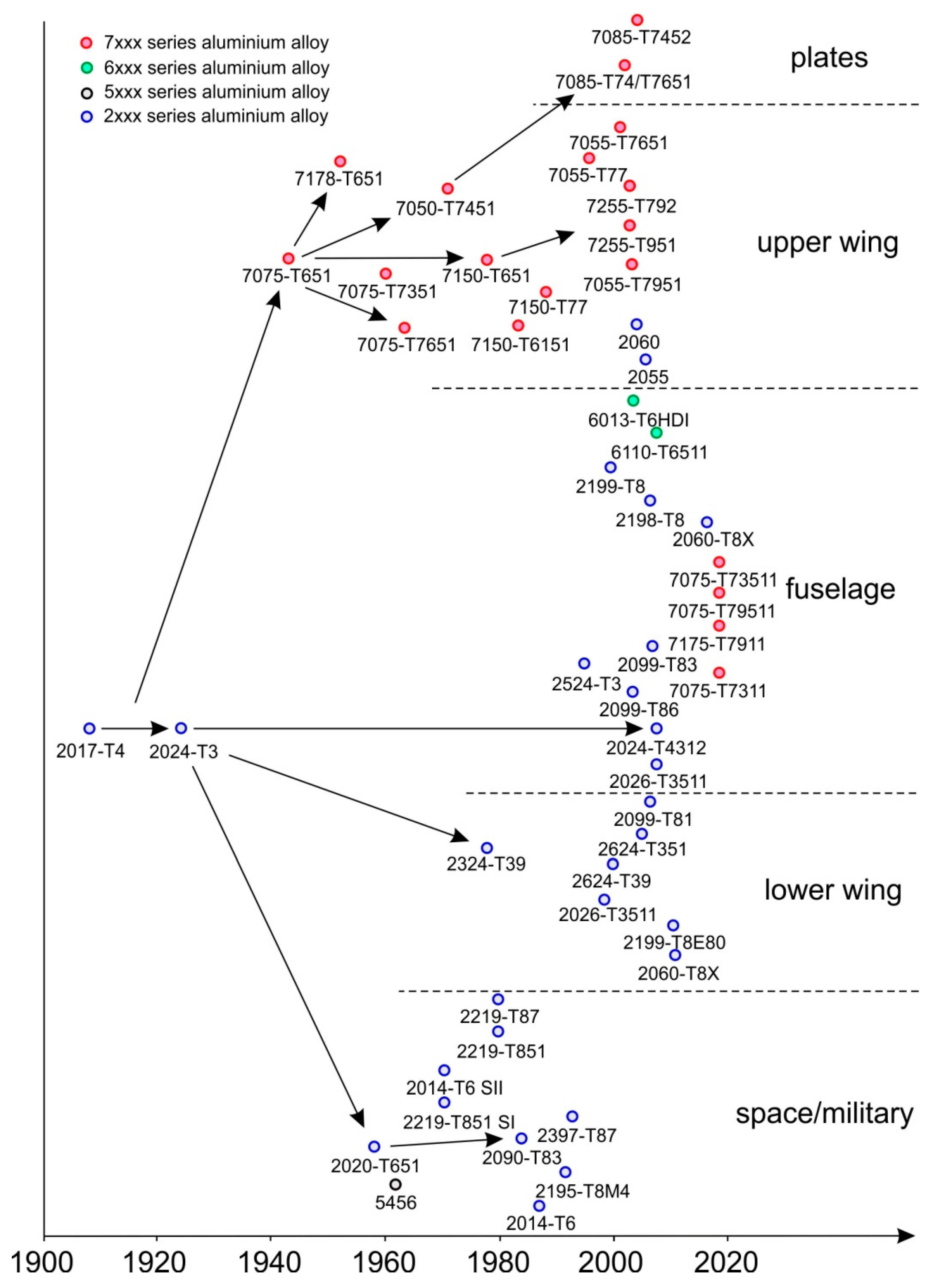
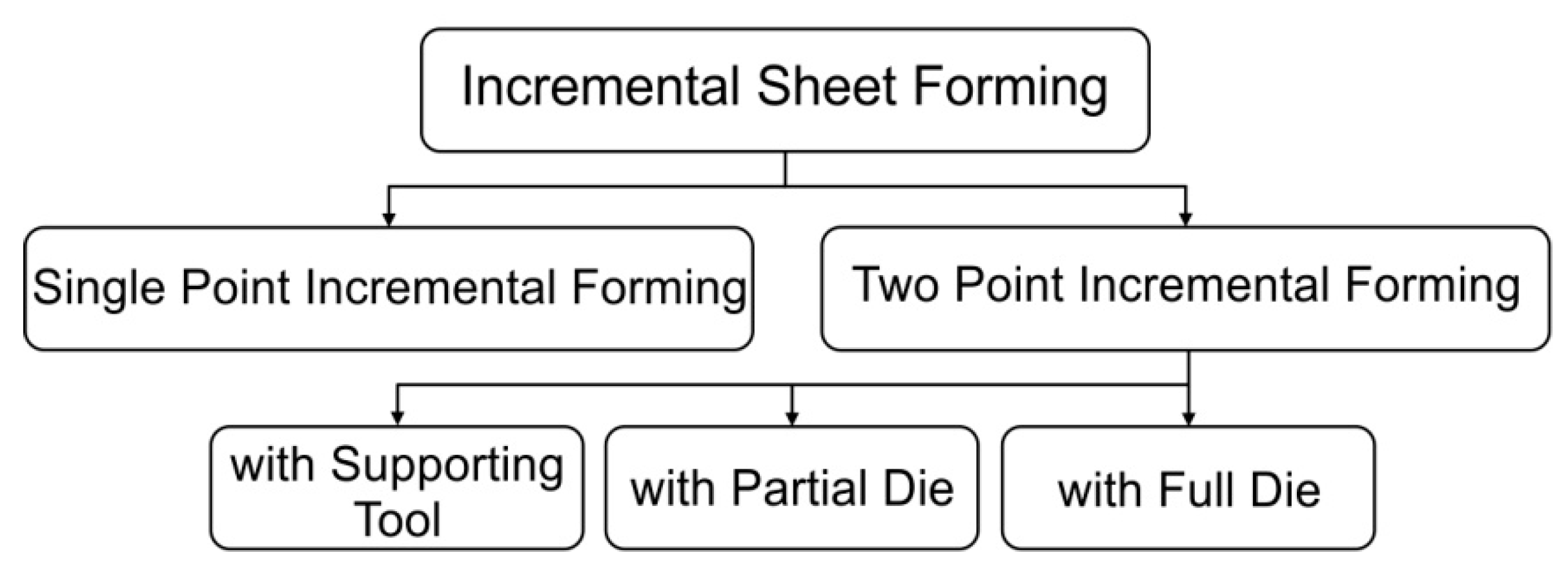
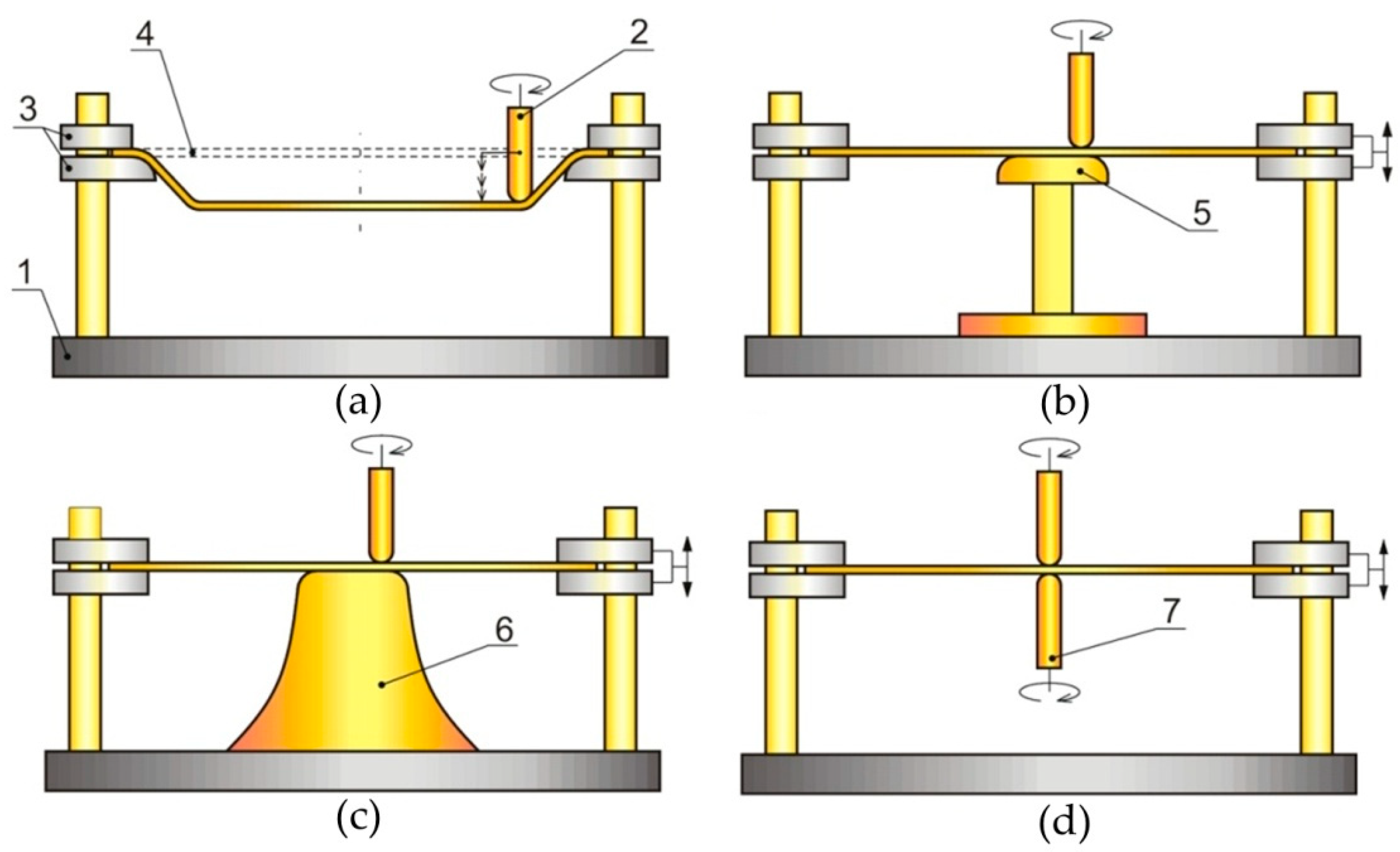
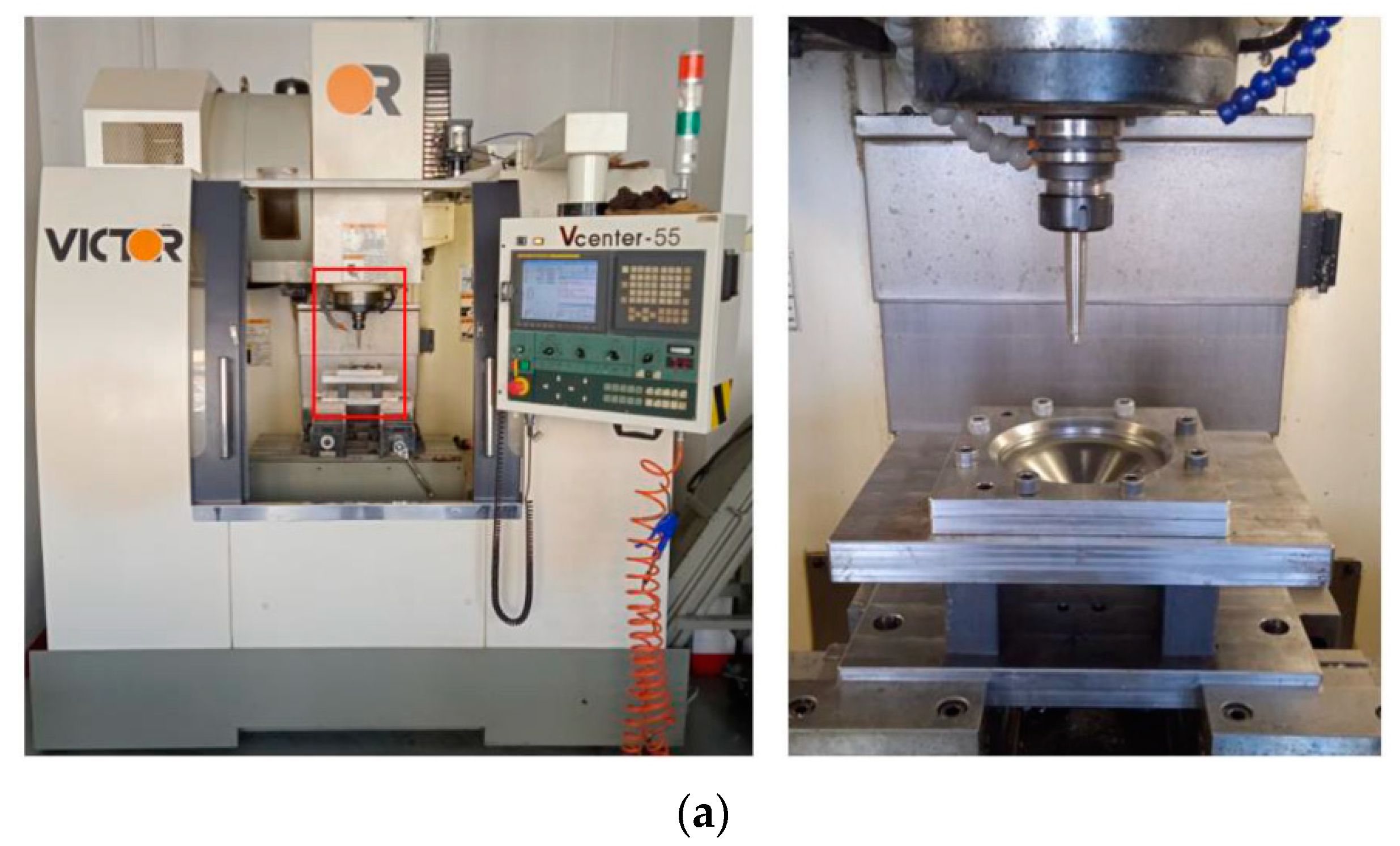
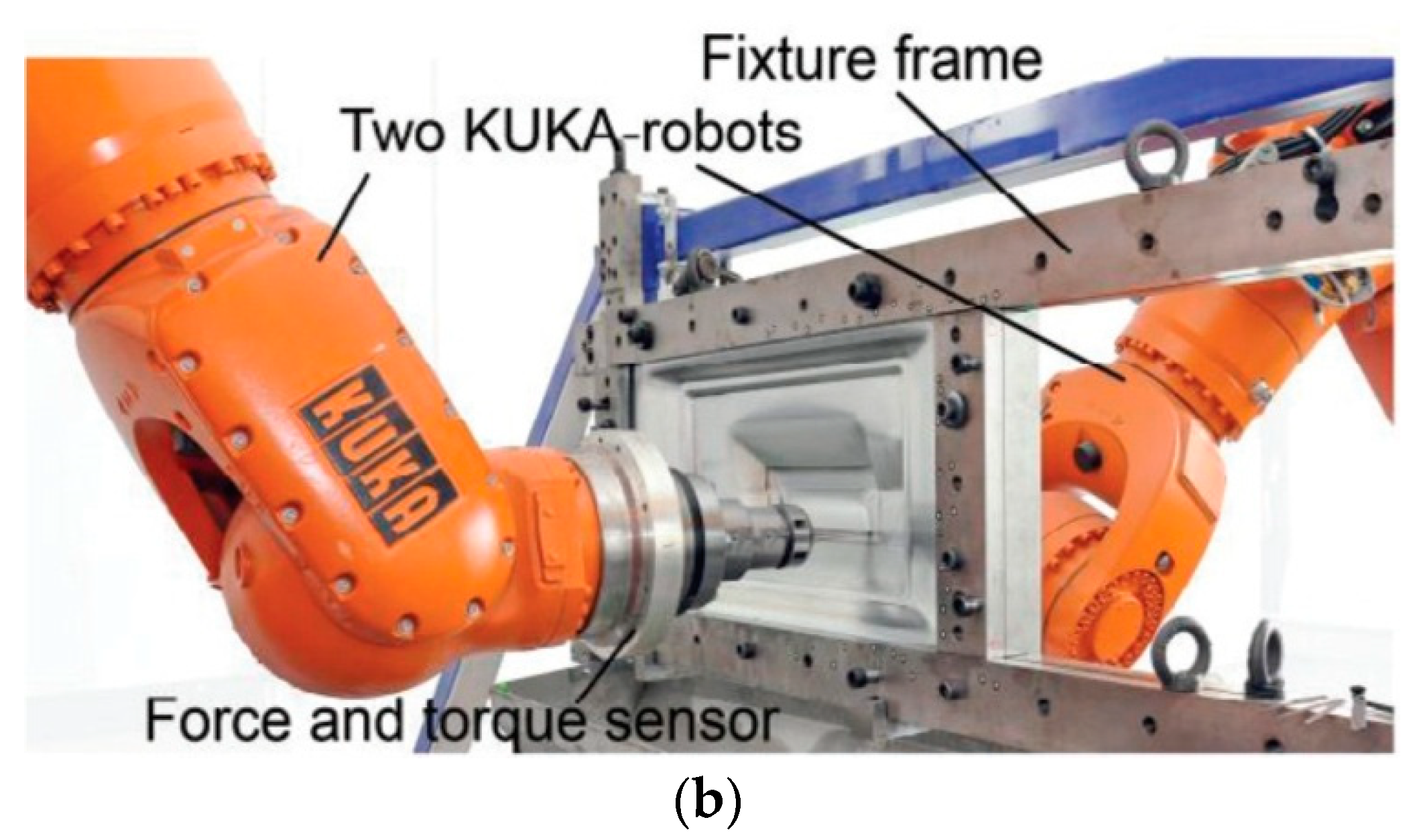
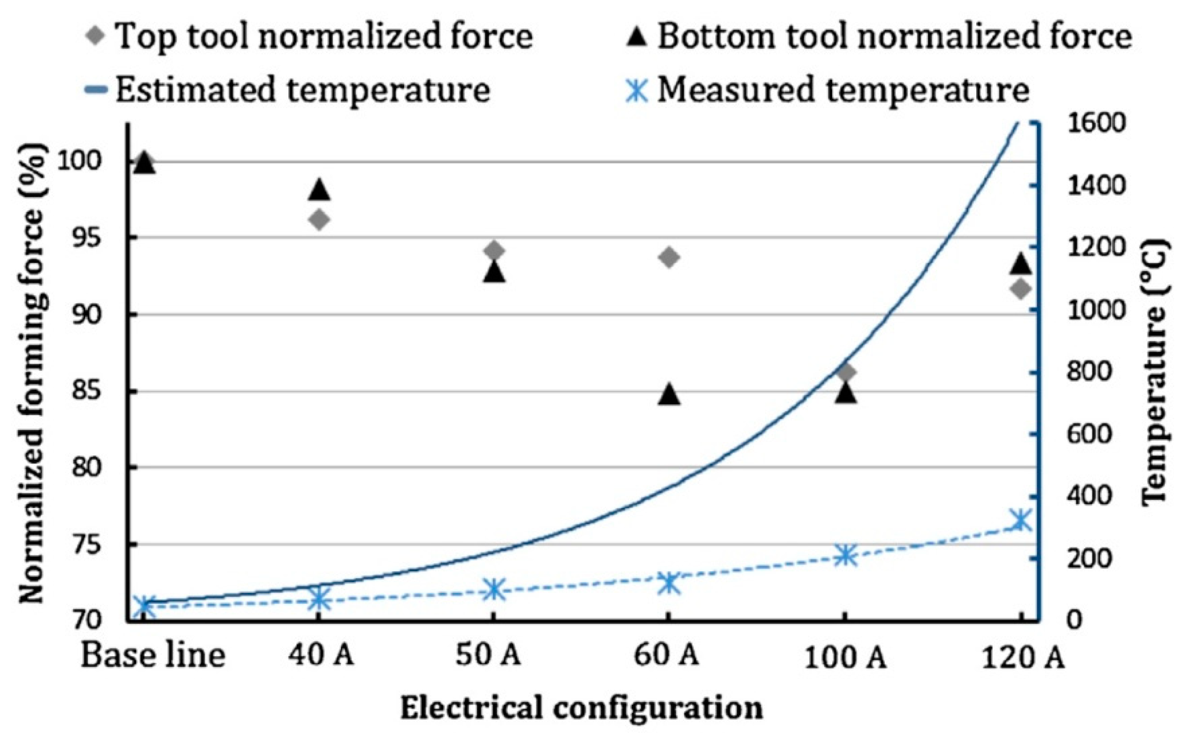
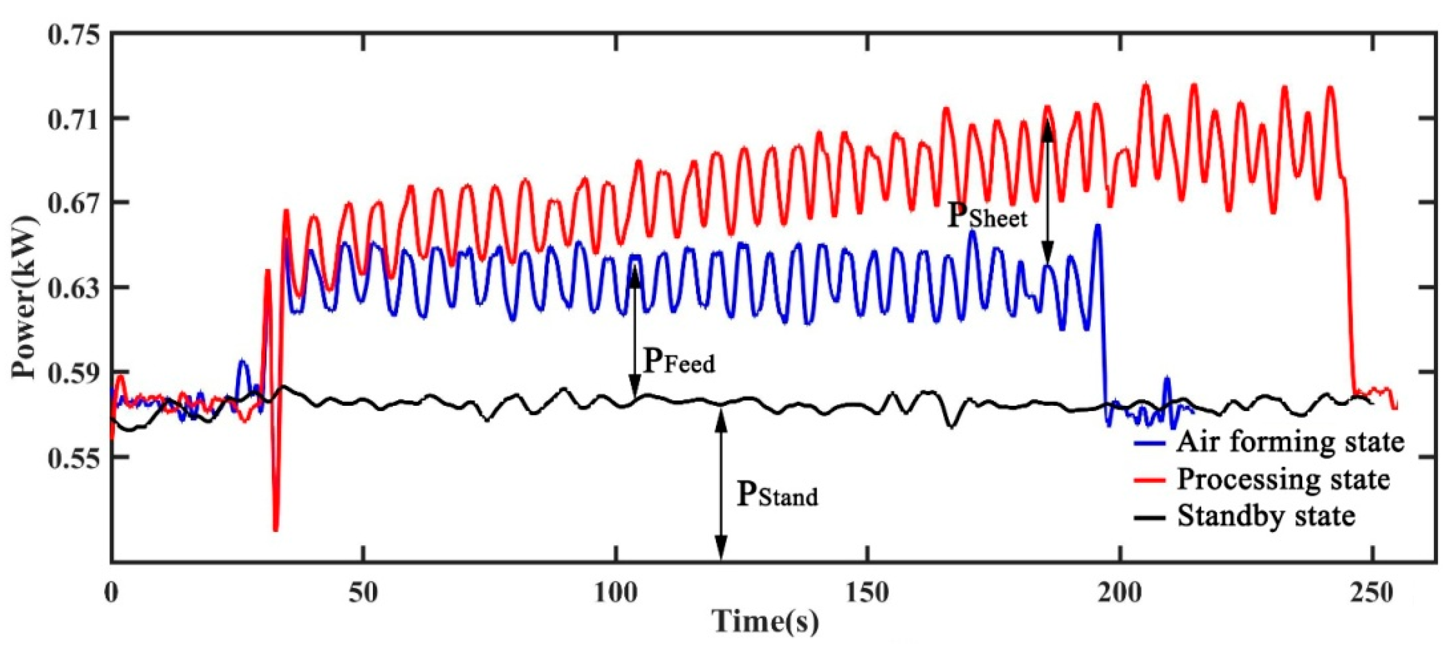
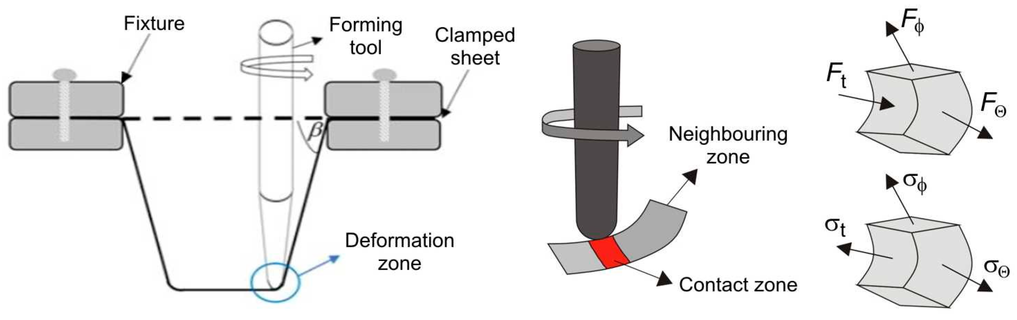
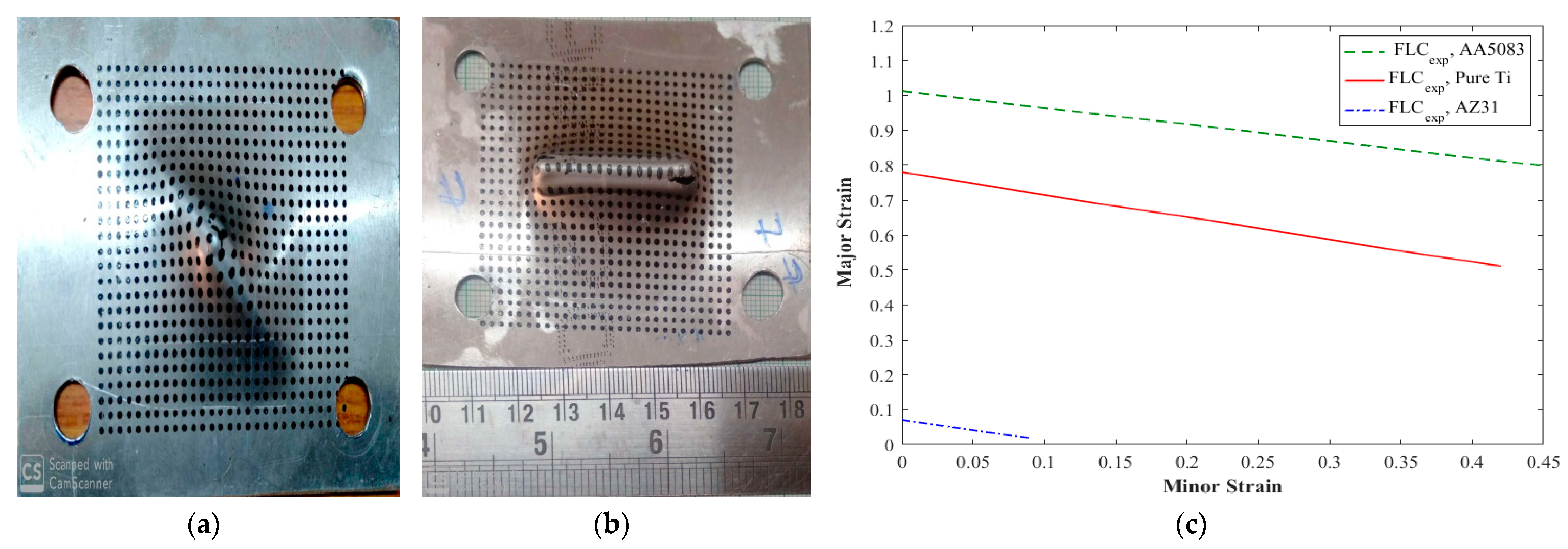
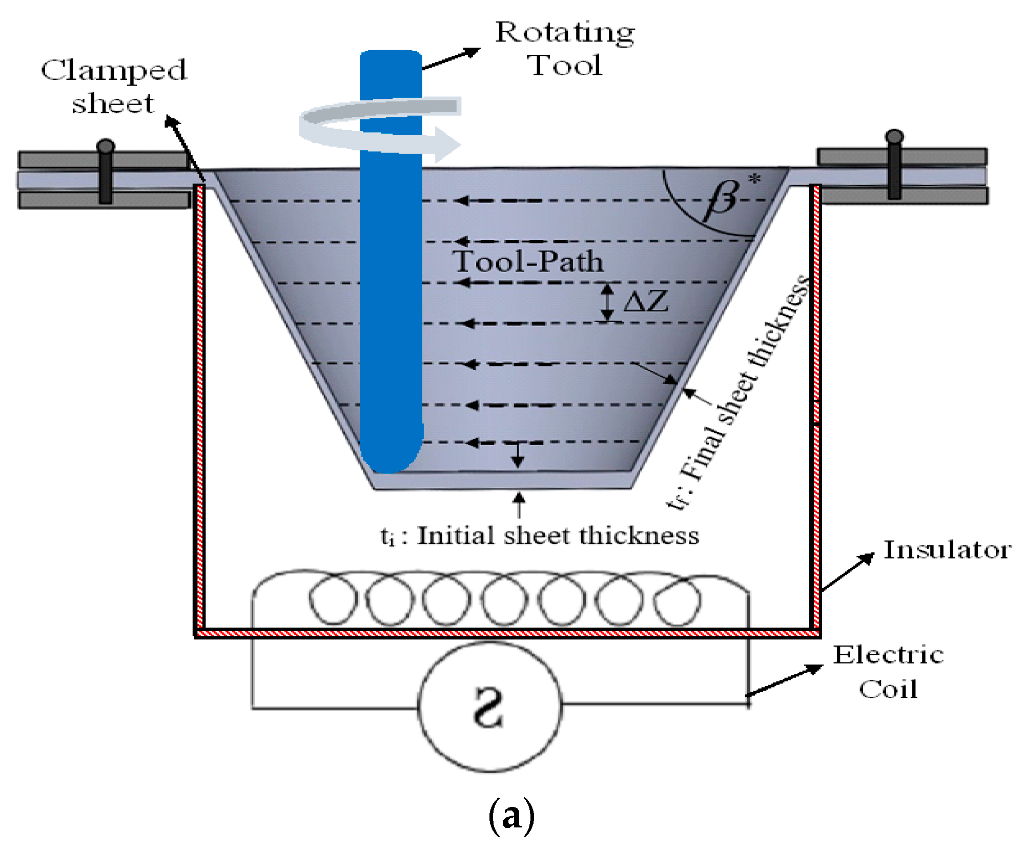
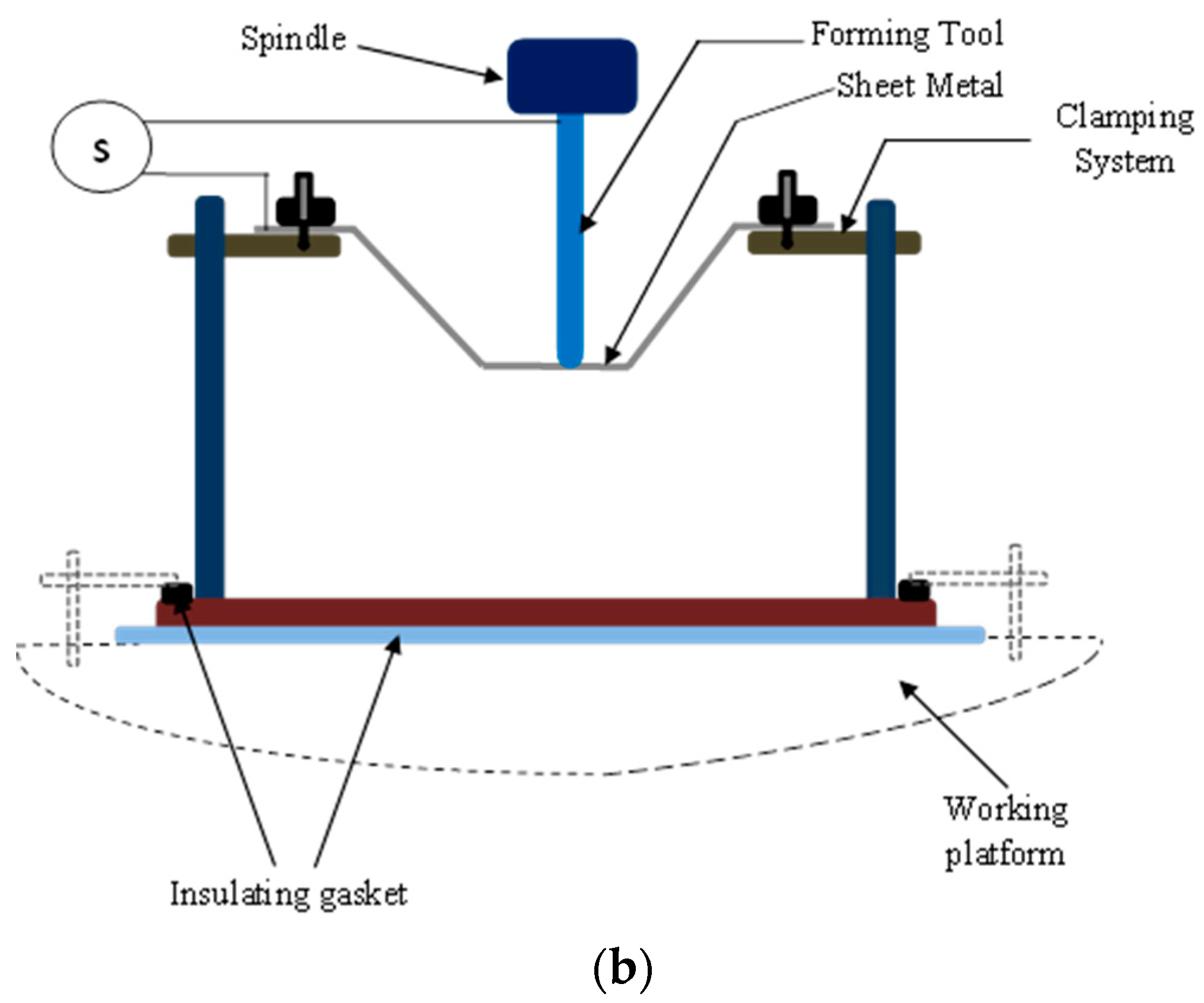
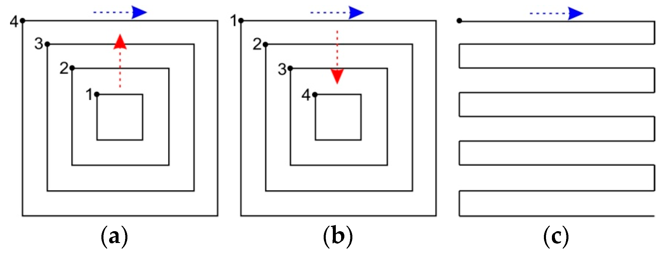
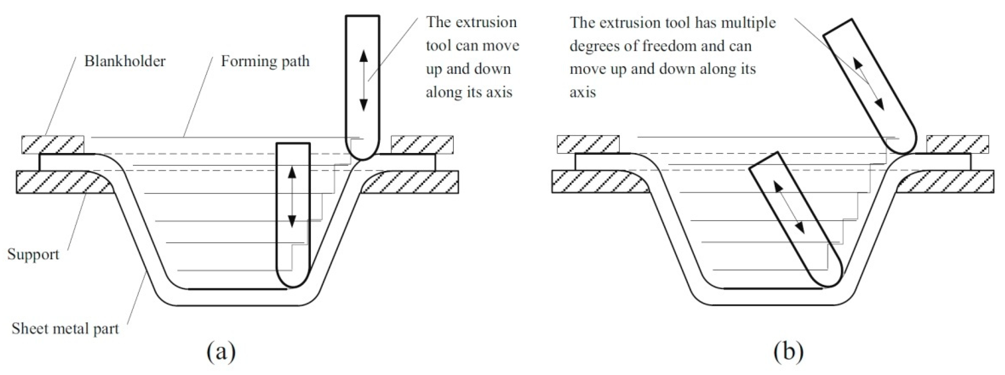
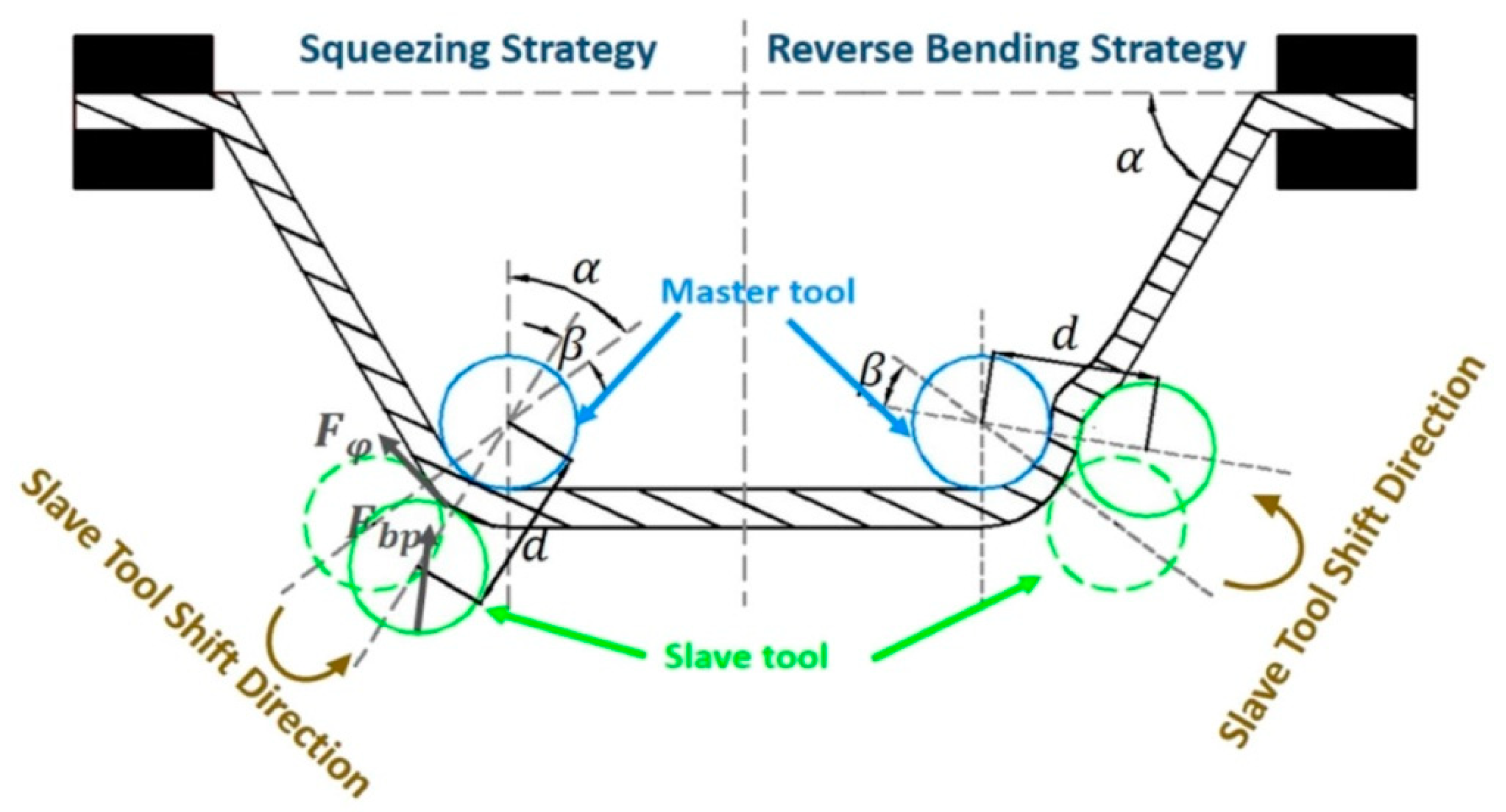
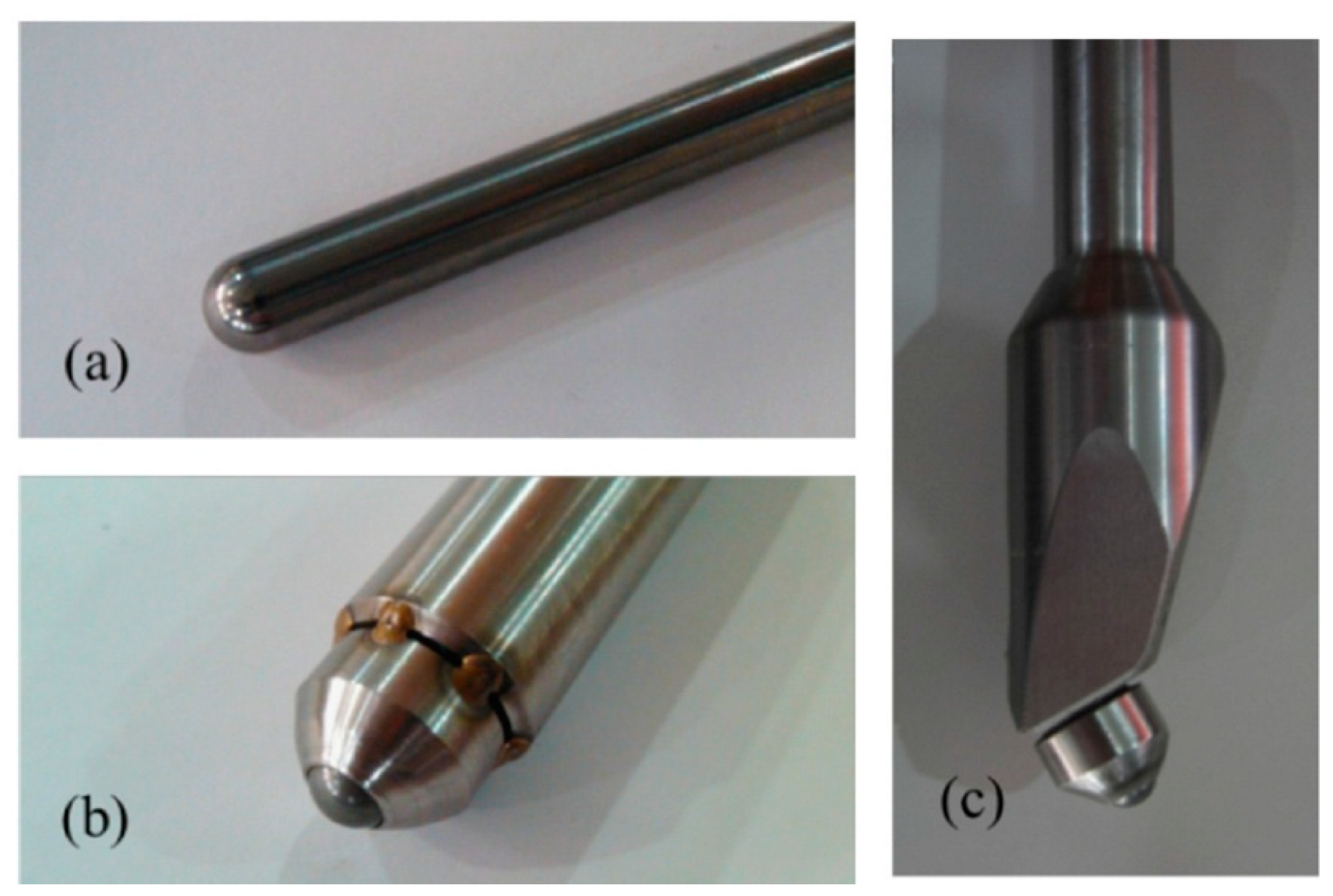
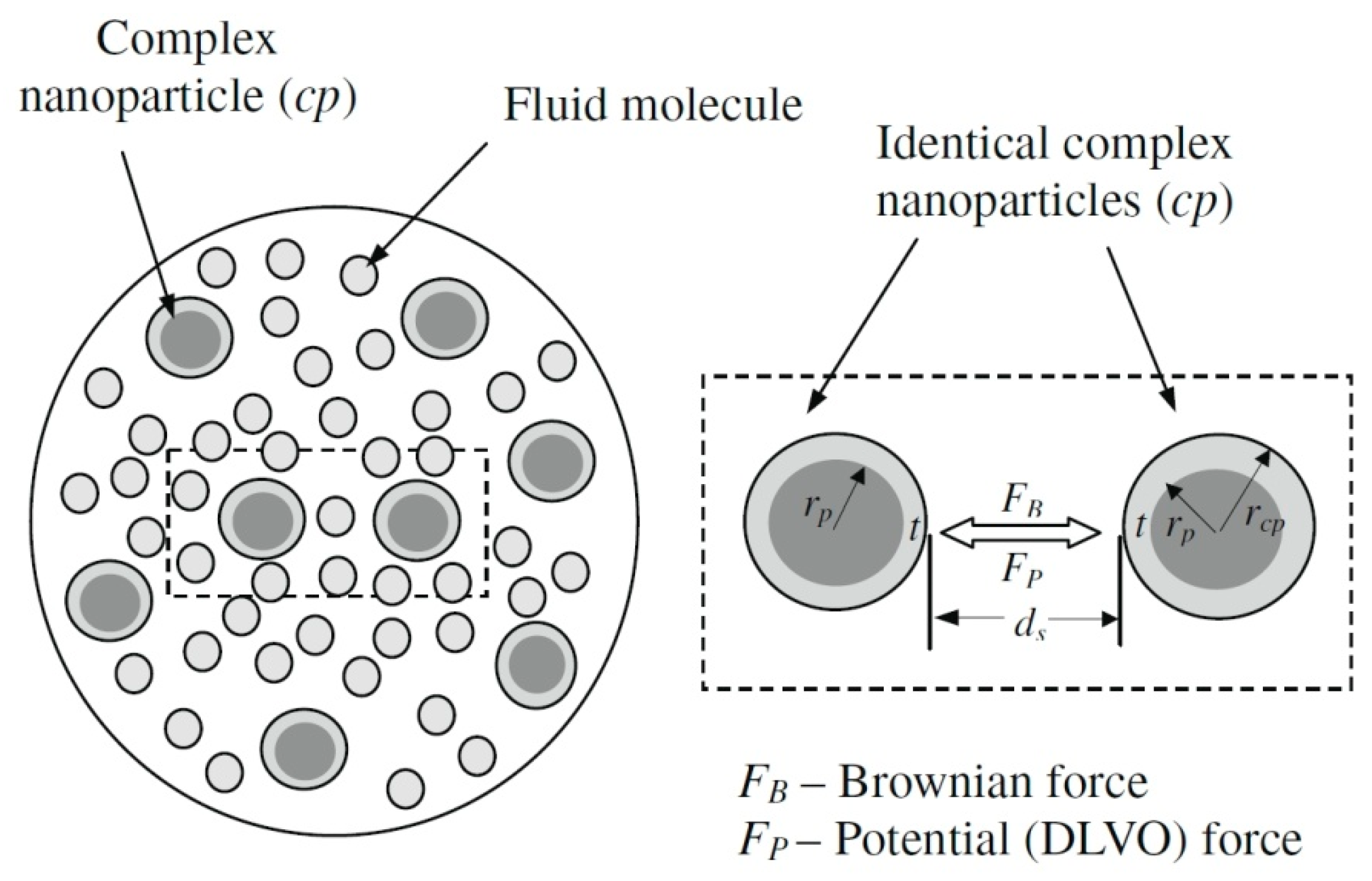
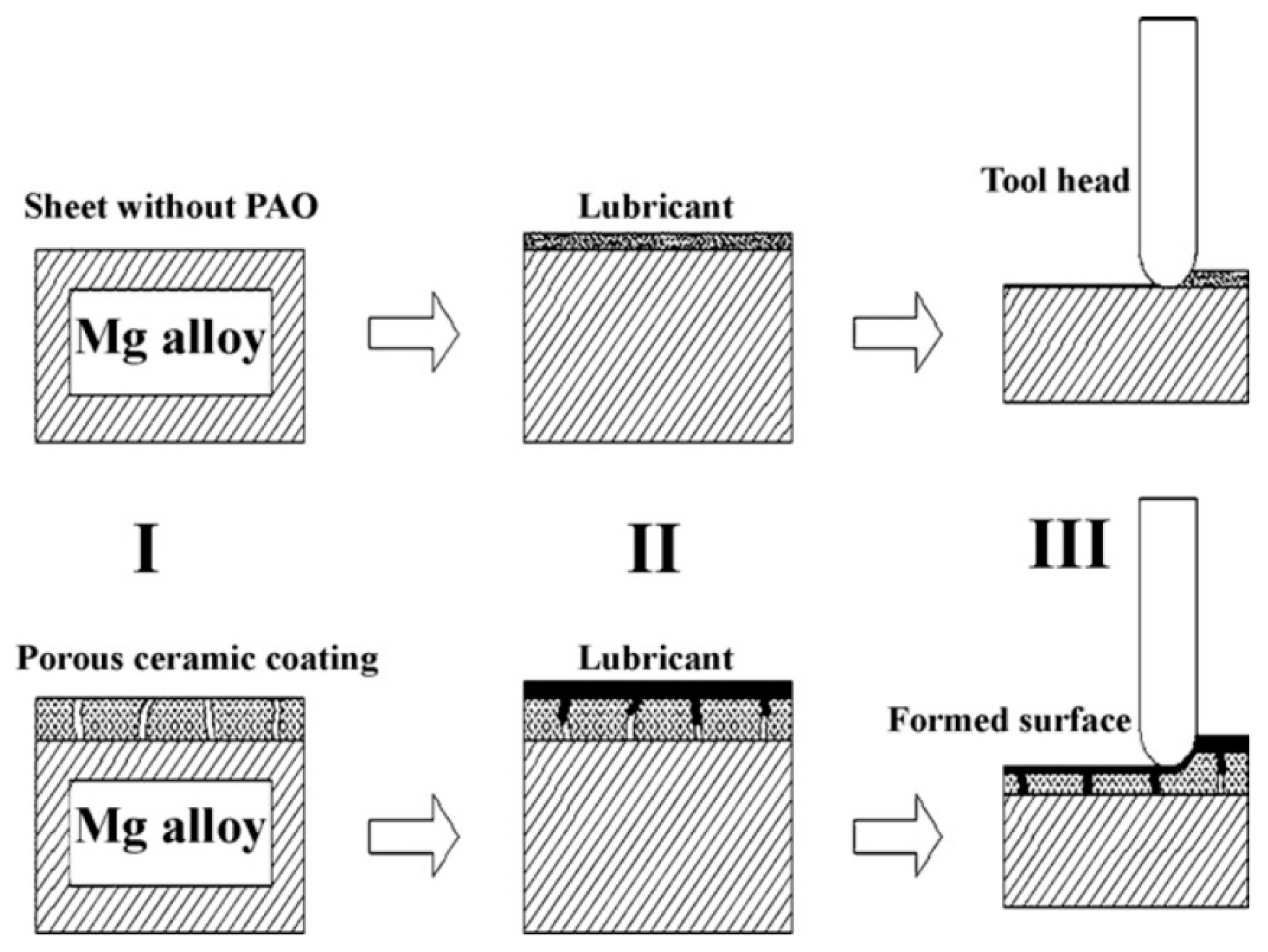
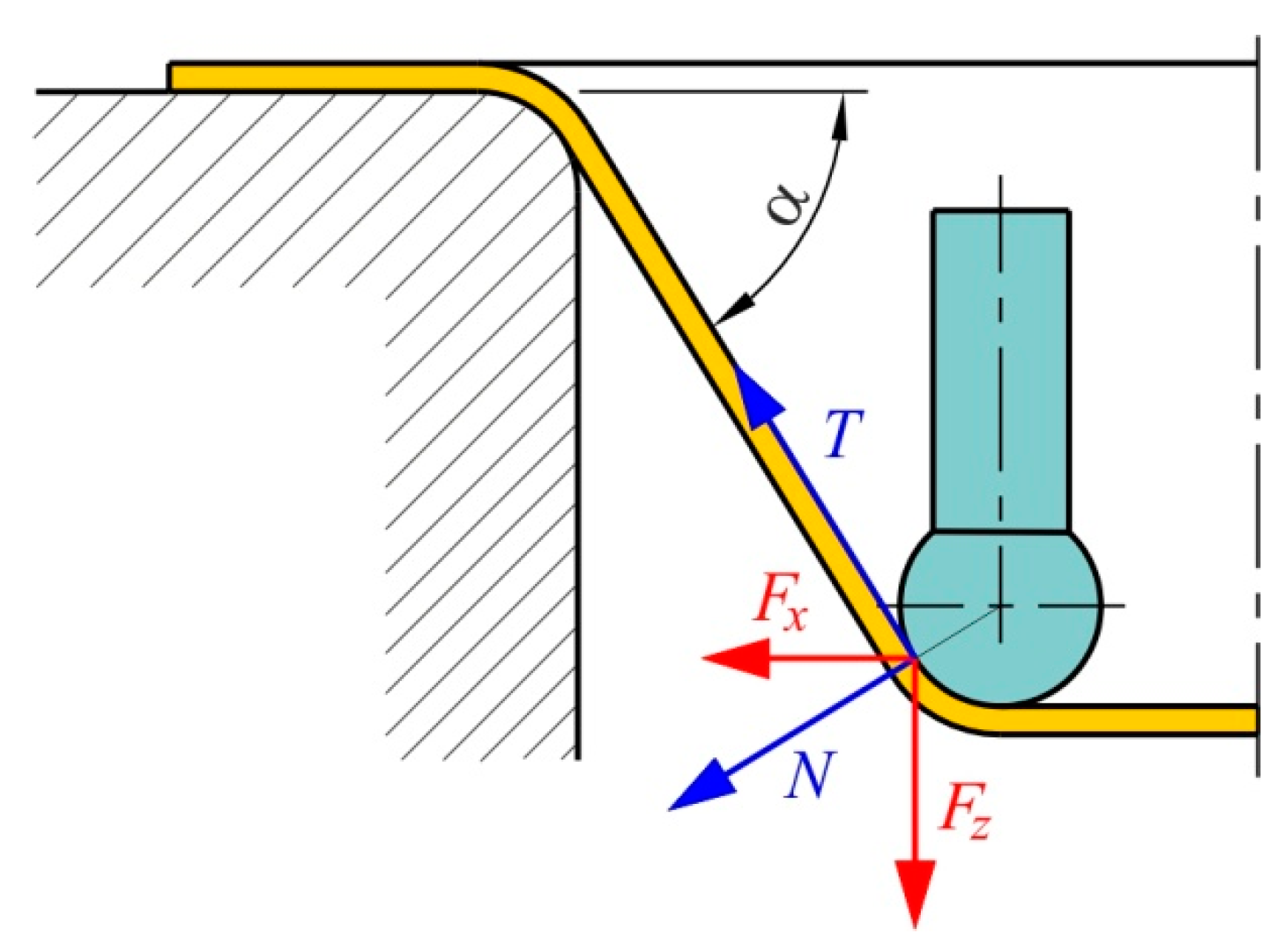
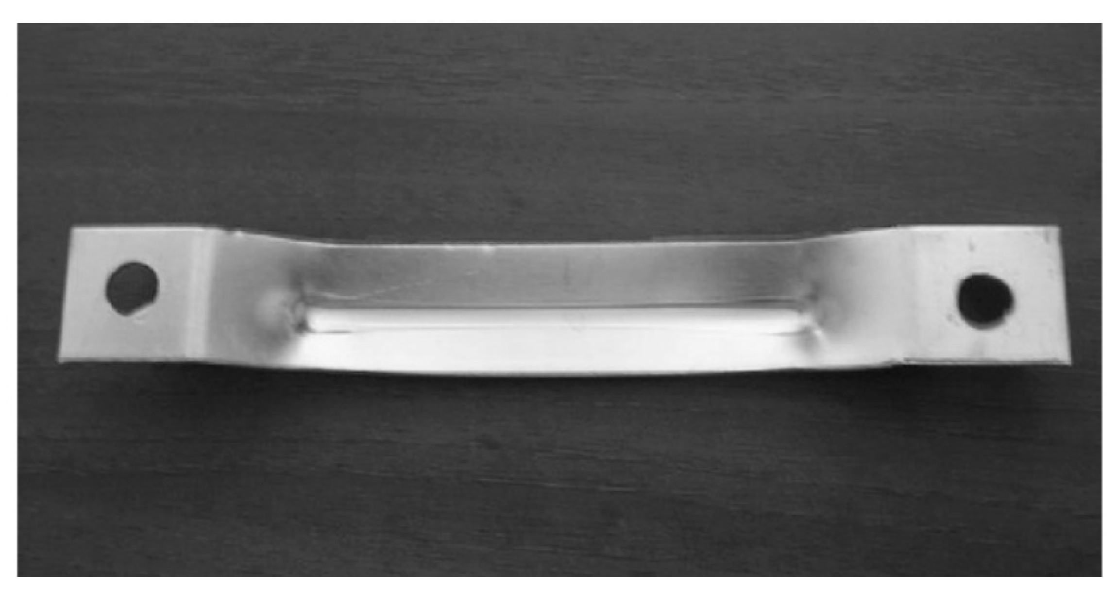
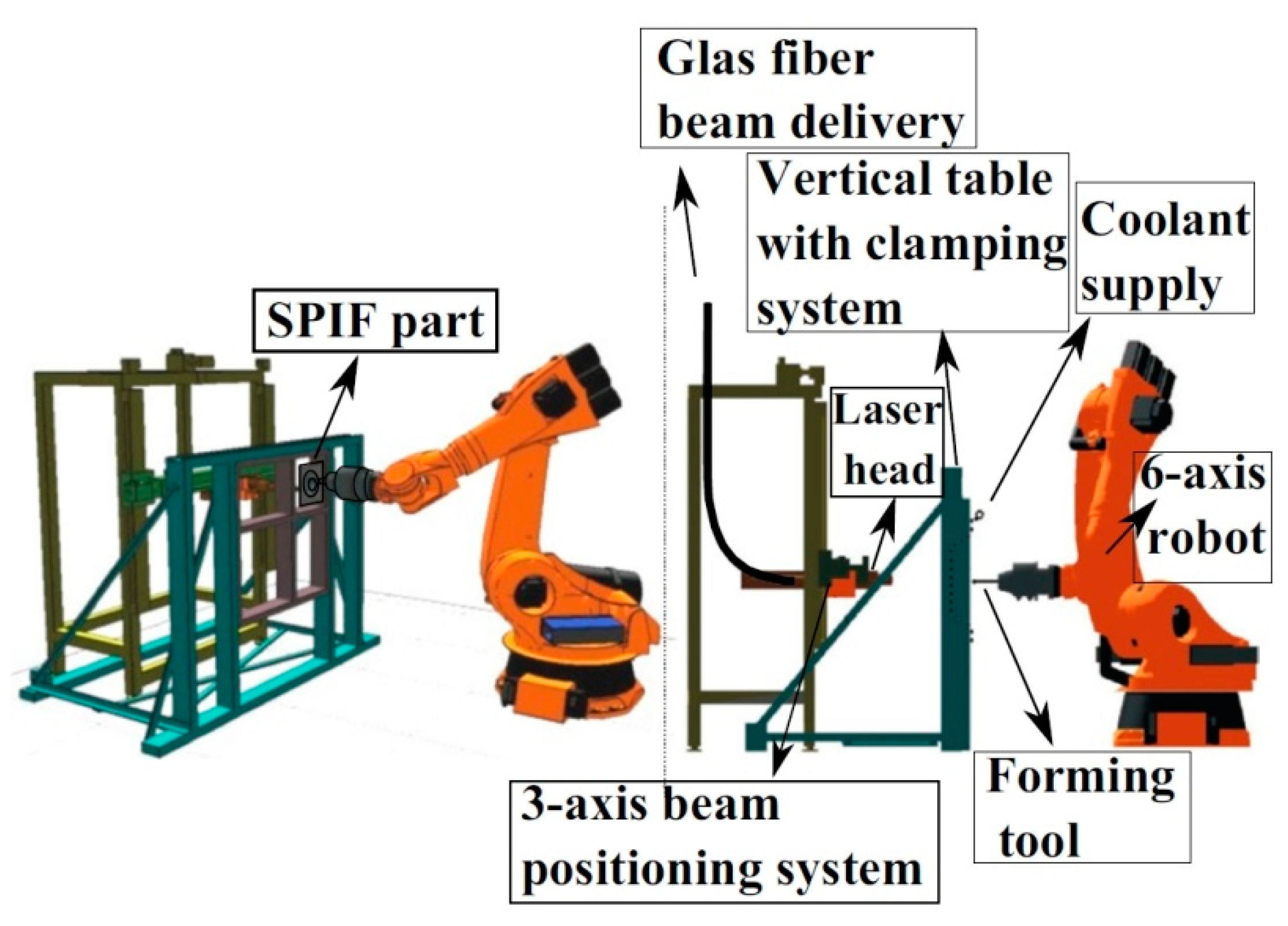
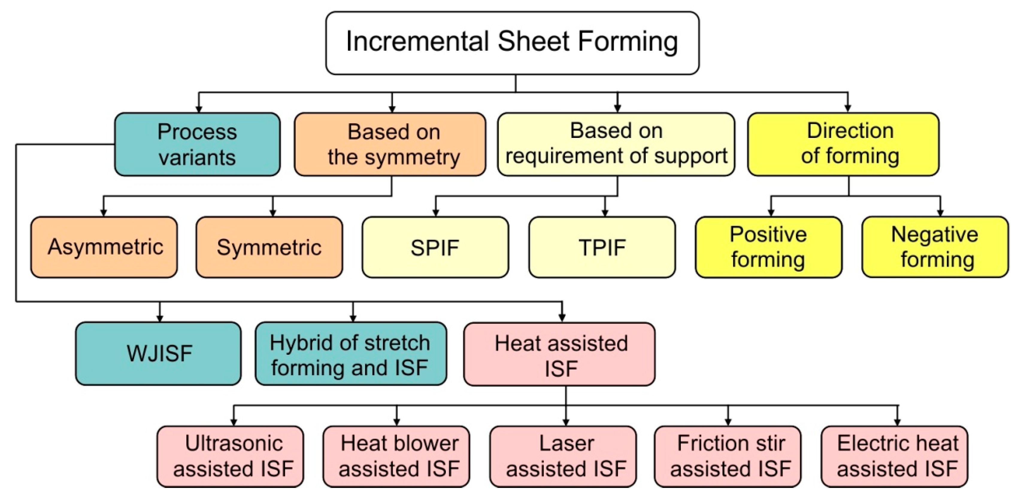
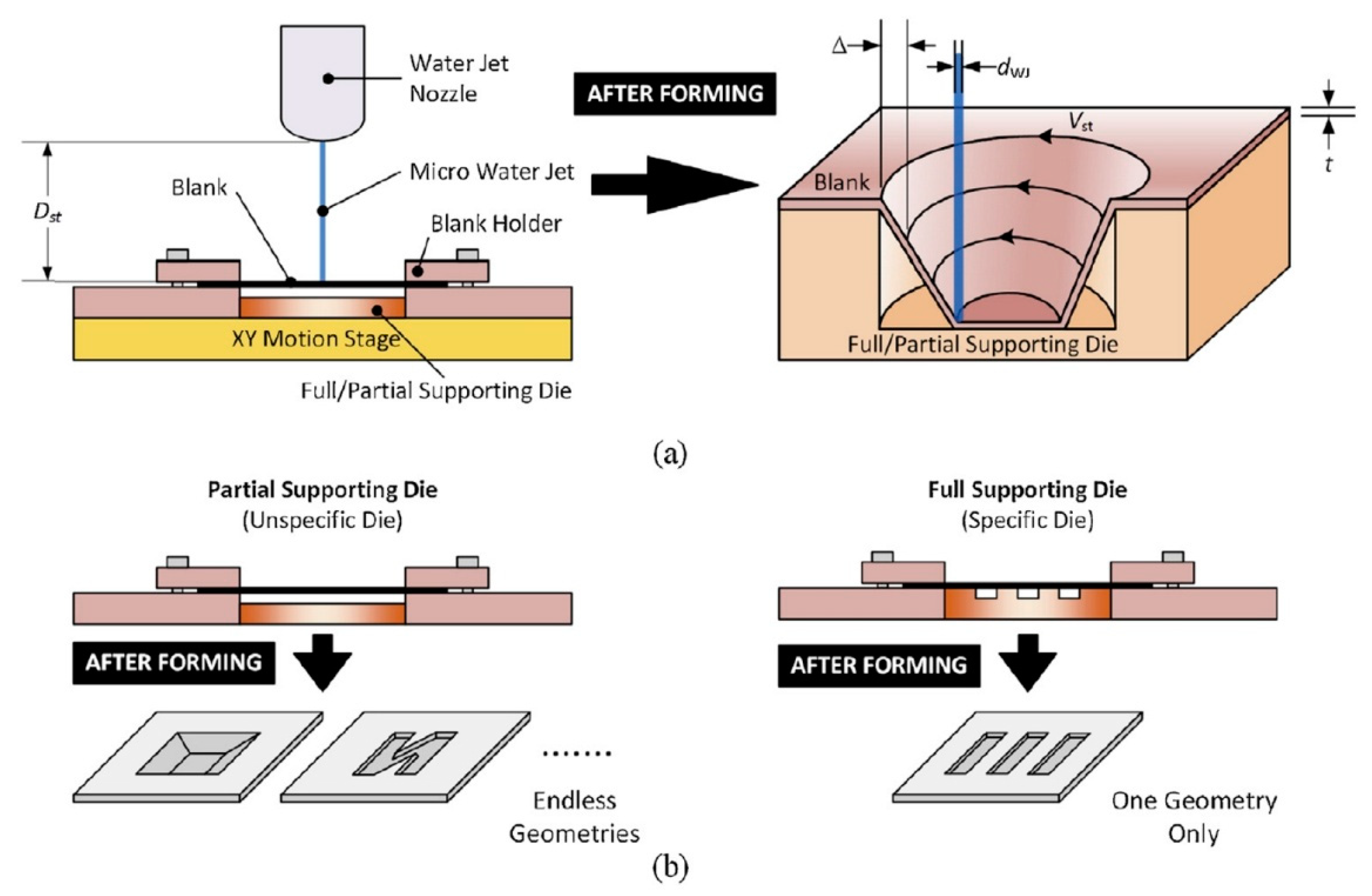
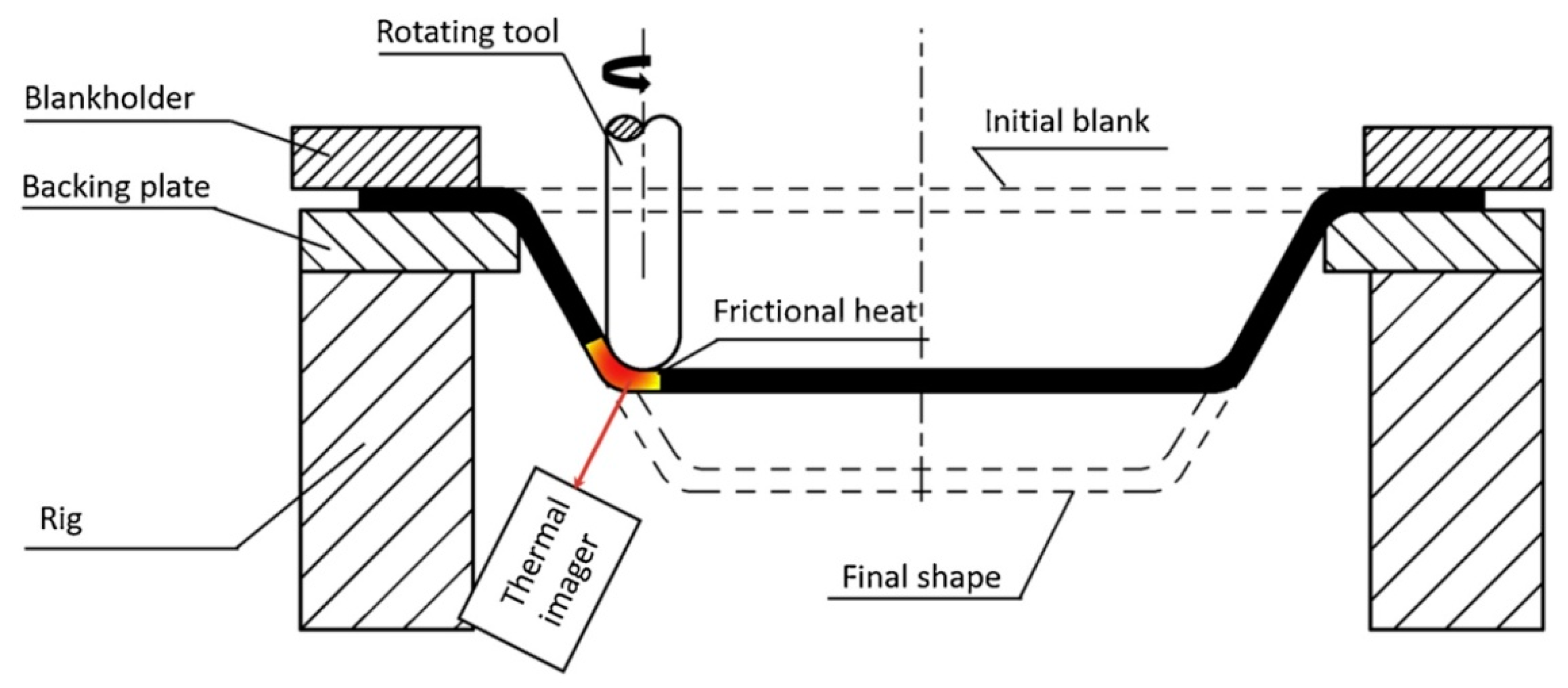
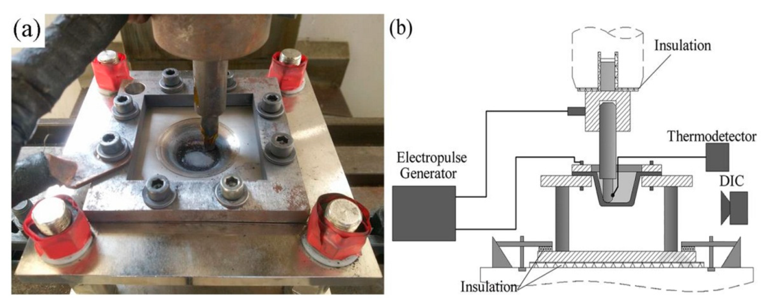
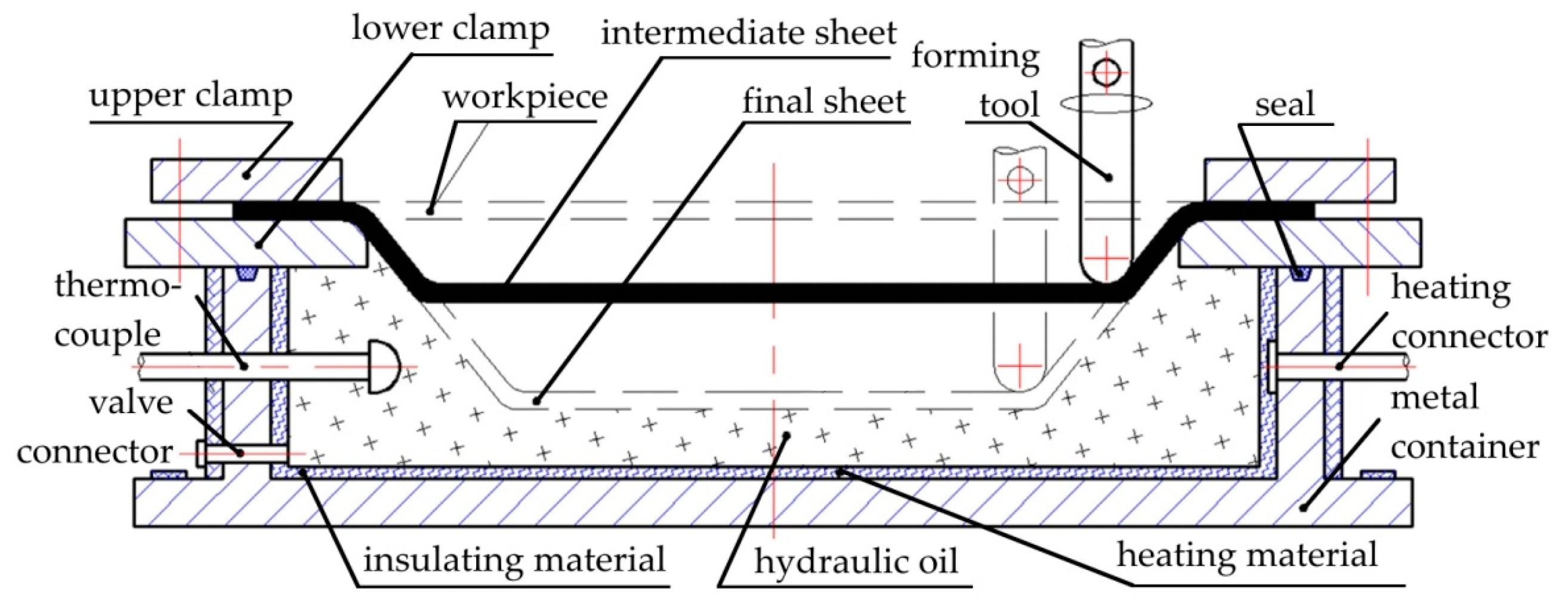
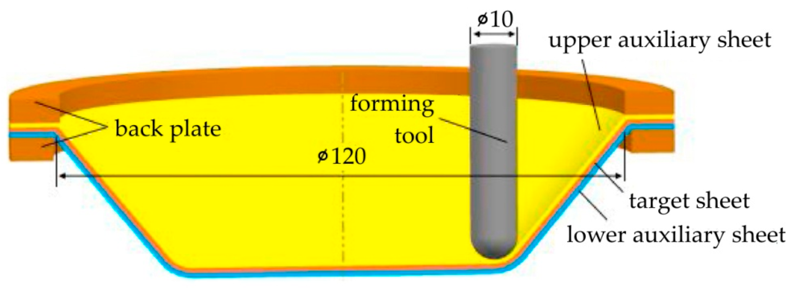
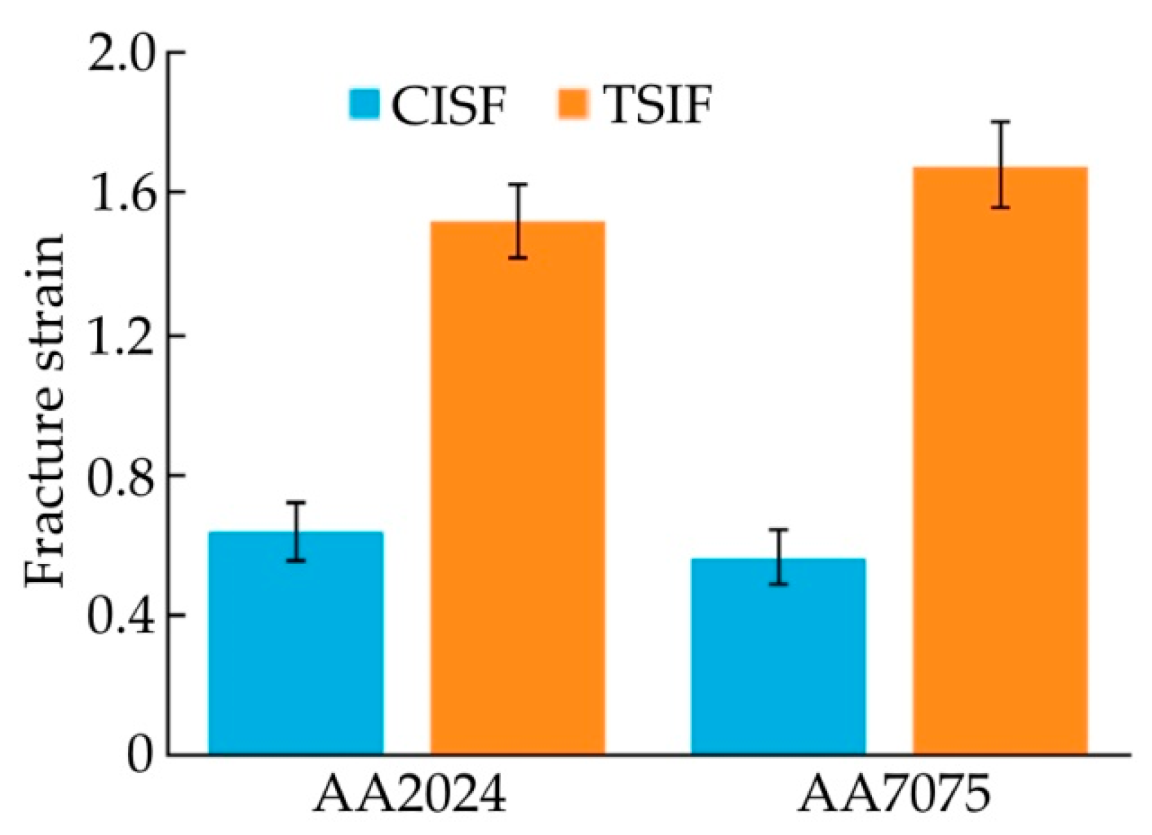
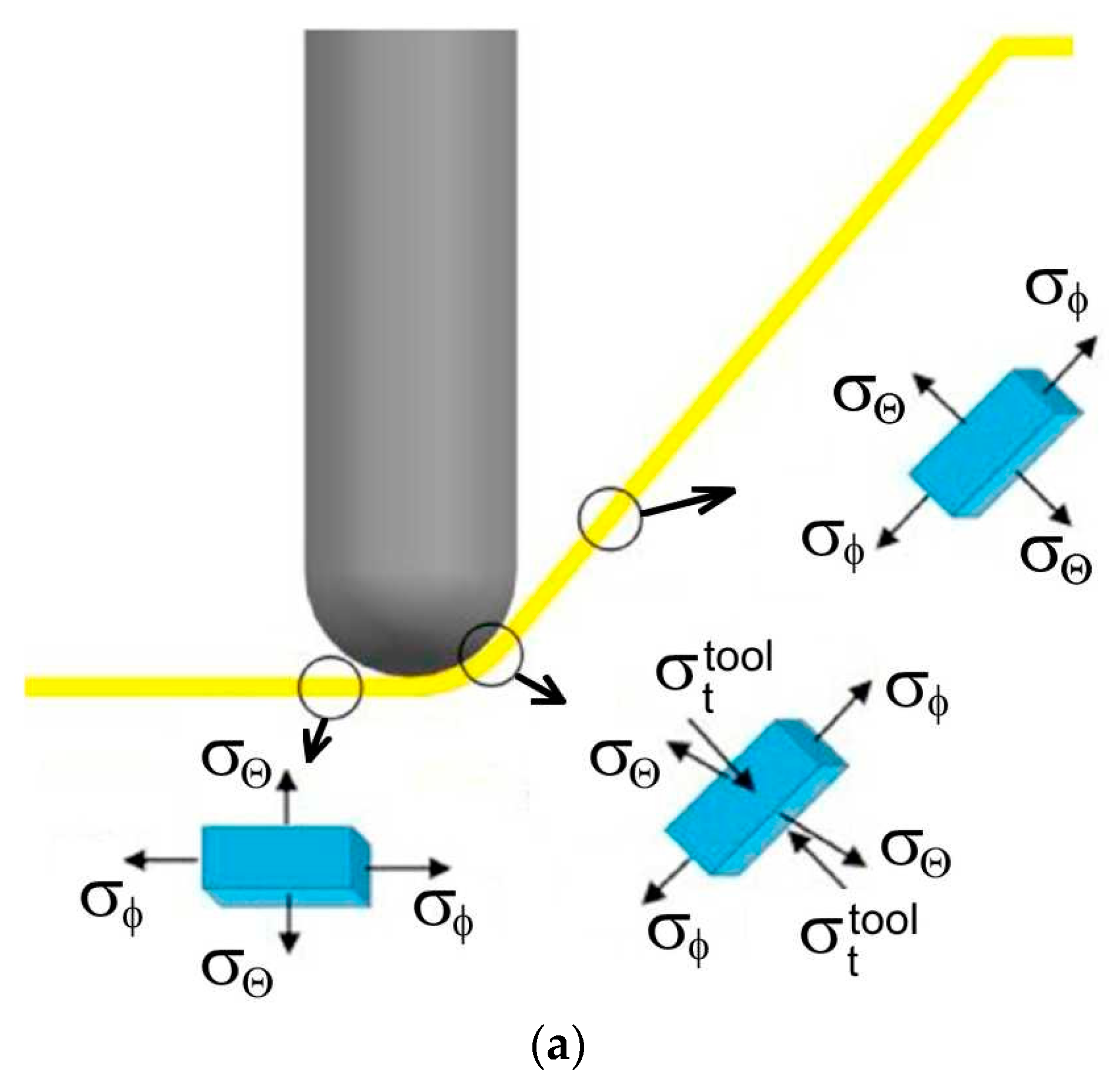
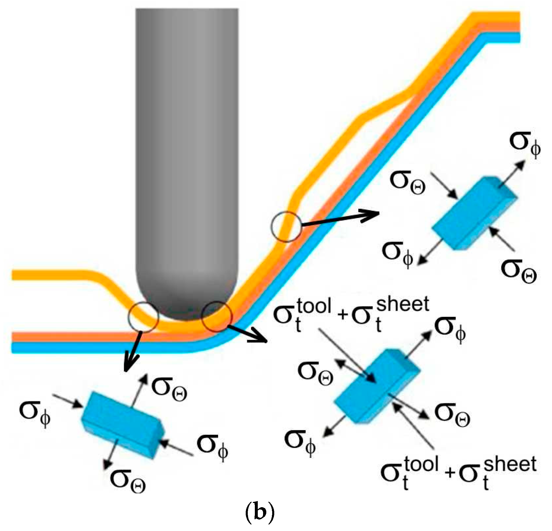
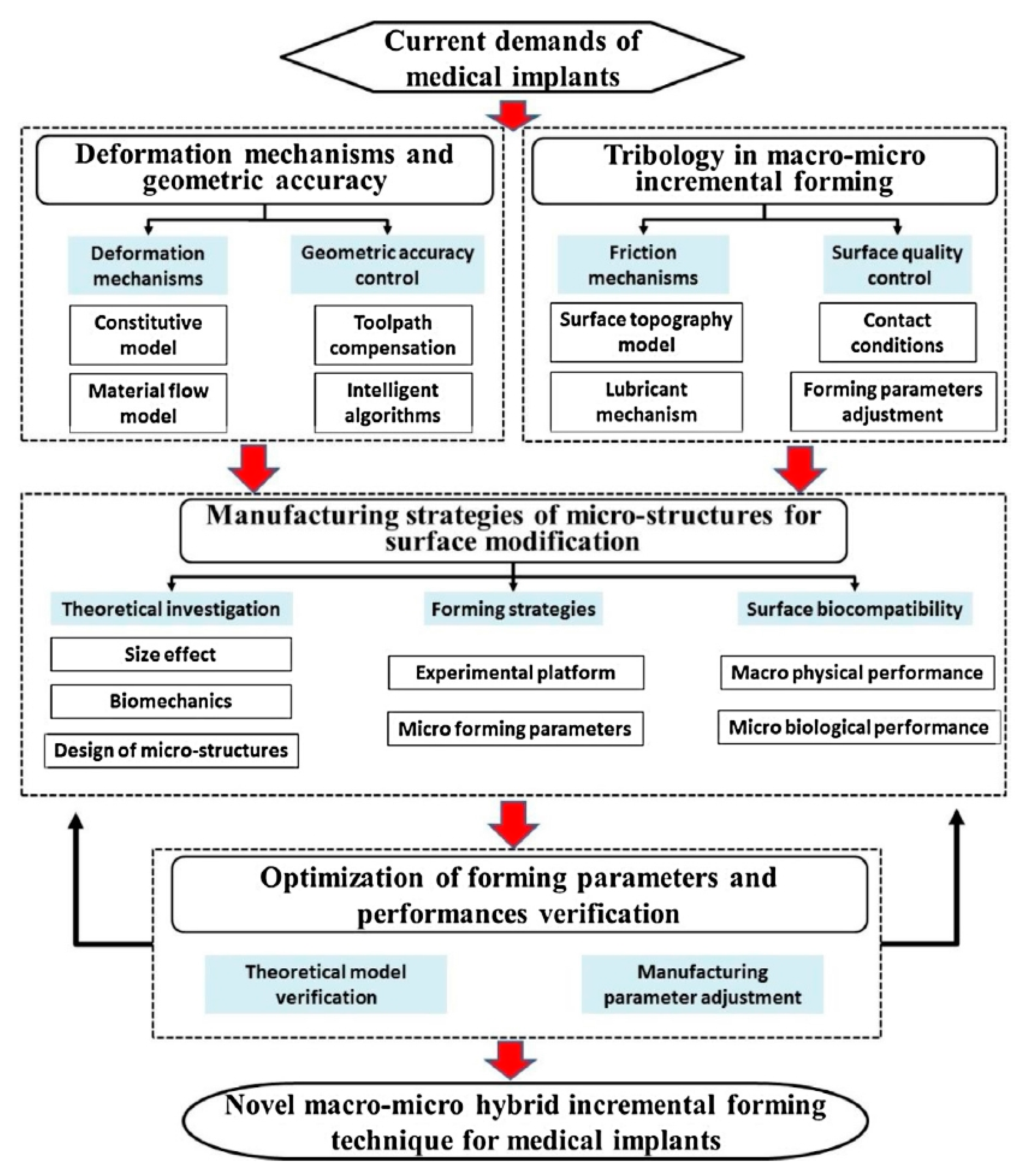
Table 1.
Overview of formability study approaches in incremental sheet forming of lightweight metals.
Table 1.
Overview of formability study approaches in incremental sheet forming of lightweight metals.
| Formability | Approaches | Summary of Findings |
|---|---|---|
| Deformation mechanism | Finite element method, Deformation stability model Ductile damage mechanics Crystal plasticity and RVE method Microstructure and texture analysis | Deformation in ISF includes stretching, bending, and shearing [123,131] Fracture is dependent on deformation stability and sheet metal ductility [124] Two-stage forming has less damage compared to the single-stage ISF [129] 3D yield function better represents the deformation in ISF [127,128] Microstructure and textural changes affect formability and strength [132,134] |
| Forming limit curve | Incremental sheet-forming tests Finite element simulation Deformation stability method Ductile damage theory Digital image processing | Fracture limit strains for plane strain and equi-biaxial strain modes [124,139] Numerical prediction of FLC is in agreement with experiments [139,141] Forming force becomes more than the supporting force in ISF [124] Shape and magnitude of FLC depends on type of loading [140] Reduced error in measurement of fracture limit strains [181] |
| Parametric study | Tool geometry and tool path Artificial neural network Design of experiments and RSM Friction and lubricants Process parameter optimisation Electro-assisted Joule heating Air-assisted heating | Formability is higher for flat tool geometry and climb tool path [147,149,154] Modeling and prediction of formability and process parameters [160,163] Parametric study and optimisation in ISF [10,159,164] Surface finish depends on friction and lubrication conditions [159,167] Optimal parameters for maximum formability [161,163,164] Higher productivity and formability with less forming force [42,48,61,167,168,169,170,171,172,173,174,175,176] Homogeneous global temperature, orange peel effect [177,178,179,180,181,182,183] |
Table 2.
Methods for optimising surface quality.
| Method | Observation | Reference |
|---|---|---|
| Novel lubrication with oil and graphite | Simple setup and low cost Improvement of step-down traces | [208] |
| Novel forming tool with backing plate | Improvement the contact conditions Reduction in lead time | [150] |
| Laser surface texturing of the forming tool | Increased material formability Friction reduction at the tool–workpiece interface Reduction in heat generation | [209] |
| Optimisation of forming strategy | Improvement of surface finish Improvement of dimensional accuracy of component | [210] |
| Tool path optimisation | Limitation of sheet thinning Improvement of surface quality | [211] |
| Usage of dummy plate | The wear of surface is avoided Dummy plate decreases the sheet formability Lubrication between sheets does not have any influence | [212] |
Table 3.
Comparative analysis of the properties of vegetable and mineral oils (reproduced with permission from Reference [227]; copyright © 2014 Elsevier).
Table 3.
Comparative analysis of the properties of vegetable and mineral oils (reproduced with permission from Reference [227]; copyright © 2014 Elsevier).
| Property | Vegetable Oil | Mineral Oil |
|---|---|---|
| Density at 20 °C (kg/m3) | 940 | 880 |
| Viscosity index | 100…200 | 100 |
| Shear stability | good | Good |
| Pour point, °C | −20 to +10 | −15 |
| Cloud flow behaviour | poor | good |
| Miscibility with mineral oils | good | - |
| Solubility in water | not miscible | not miscible |
| Oxidation stability | moderate | good |
| Hydrolytic stability | poor | good |
| Sludge forming tendency | poor | good |
| Seal swelling tendency | slight | slight |
Table 4.
The basic physicochemical properties of vegetable oils (reproduced with permission from Reference [227]; copyright © 2014 Elsevier).
Table 4.
The basic physicochemical properties of vegetable oils (reproduced with permission from Reference [227]; copyright © 2014 Elsevier).
| Oil Type | Density, kg/m3 | Kinematic Viscosity at 40 °C, mm2/s | Cloud Point, °C | Flash Point, °C |
|---|---|---|---|---|
| palm | 875 | 5.72 | 13.0 | 165 |
| sunflower | 878 | 4.45 | 3.42 | 185 |
| coconut | 805 | 2.75 | 0 | 112 |
| soybean | 885 | 4.05 | 1.0 | 176 |
| linseed | 890 | 3.74 | −3.8 | 178 |
| olive | 892 | 4.52 | - | 179 |
| peanut | 882 | 4.92 | 5.0 | 177 |
| rape seed | 880 | 4.45 | −3.3 | 62 |
| rice bran | 886 | 4.95 | 0.3 | - |
Table 5.
Typical lubricants used in SPIF of selected materials.
| Lubricant | Material | Shape of Drawpiece | Reference |
|---|---|---|---|
| nano-K2Ti4O9 whisker and organic binder | AZ31 | truncated pyramid | [228] |
| solid graphite powder, MoS2 grease, MLS2 Lithium grease | AZ31 | truncated cone | [229] |
| oil coolant and grease | Al1100 | truncated cone | [235] |
| 75W-140 gear oil, used cooking oil | Al-3003O | hat-shaped component | [236] |
| Mineral oil | AA5754 | truncated cone truncated pyramid | [237] |
| SAE 20w-40 | AA6061 | truncated cone | [230] |
| cutting oil | AA2024 | complex part | [238] |
| mineral oil | AA2024-T4 | truncated cone | [239] |
| SAE 75W-85 gear oil | AA2024-T3 | rib-stiffened panel | [231] |
| mineral oil | AA2219-O AA2219-T6 | frustum pyramid | [240] |
| engine oil (grade not provided) PTFE based grease | AA 5052 | truncated pyramid 70° cone and funnel | [181,241] [242] |
| solid graphite powder, MoS2 grease, MLS2 lithium grease | AA5055 | truncated cone | [229] |
| Alpha SP 68, Alpha SP 150, Alpha SP 320 | AA6063-O | truncated cone | [66] |
| SAE 75W-85 gear oil | 7075-T6 | rib-stiffened panel | [231] |
| solid graphite powder, boron nitride spray ROCOL RTD liquid vegetable oils | Ti-6Al-4V | truncated cone cranial implant truncated cone | [40] [150] [243] |
| mixture of MoS2 powder grease | pure titanium | truncated cone | [244] |
| chlorine-containing forming oils | titanium grade 1 | denture plate | [193] |
| Nuto 46 hydraulic oil ceramic grease WEICON ASW 040P MoS2 | titanium grade 2 | clavicle facial implant dome-like shape | [152] [245] [246] |
Publisher’s Note: MDPI stays neutral with regard to jurisdictional claims in published maps and institutional affiliations. |
© 2021 by the authors. Licensee MDPI, Basel, Switzerland. This article is an open access article distributed under the terms and conditions of the Creative Commons Attribution (CC BY) license (https://creativecommons.org/licenses/by/4.0/).
Share and Cite
MDPI and ACS Style
Trzepieciński, T.; Oleksik, V.; Pepelnjak, T.; Najm, S.M.; Paniti, I.; Maji, K. Emerging Trends in Single Point Incremental Sheet Forming of Lightweight Metals. Metals 2021, 11, 1188. https://doi.org/10.3390/met11081188
AMA Style
Trzepieciński T, Oleksik V, Pepelnjak T, Najm SM, Paniti I, Maji K. Emerging Trends in Single Point Incremental Sheet Forming of Lightweight Metals. Metals. 2021; 11(8):1188. https://doi.org/10.3390/met11081188
Chicago/Turabian StyleTrzepieciński, Tomasz, Valentin Oleksik, Tomaž Pepelnjak, Sherwan Mohammed Najm, Imre Paniti, and Kuntal Maji. 2021. "Emerging Trends in Single Point Incremental Sheet Forming of Lightweight Metals" Metals 11, no. 8: 1188. https://doi.org/10.3390/met11081188
Note that from the first issue of 2016, this journal uses article numbers instead of page numbers. See further details here.