
Enhancement of the Interlaminar Fracture Toughness of a Carbon-Fiber-Reinforced Polymer Using Interleaved Carbon Nanotube Buckypaper

1
Department of Mechanical and Aerospace Engineering, Seoul National University, 1 Gwanak-ro, Gwanak-gu, Seoul 08826, Korea
2
School of Mechanical Engineering, Korea University of Technology and Education, 1600 Chungjeol-ro, Byeongcheon-myeon, Dongnam-gu, Cheonan-si 31253, Korea
*
Author to whom correspondence should be addressed.
Appl. Sci. 2021, 11(15), 6821; https://doi.org/10.3390/app11156821
Submission received: 30 June 2021
/
Revised: 14 July 2021
/
Accepted: 20 July 2021
/
Published: 24 July 2021
(This article belongs to the Special Issue Additive Manufacturing for Composite Materials)
Abstract
:In this study, a carbon nanotube (CNT) buckypaper was interleaved in a carbon-fiber-reinforced polymer (CFRP) composite to improve the interlaminar fracture toughness. Interleaving the film of a laminate-type composite poses the risk of deteriorating the in-plane mechanical properties. Therefore, the in-plane shear modulus and shear strength were measured prior to estimating the interlaminar fracture toughness. To evaluate the effect of the buckypaper on the interlaminar fracture toughness of the CFRP, double cantilever beam (DCB) and end notch flexure (ENF) tests were conducted for mode I and mode II delamination, respectively. No significant change was observed for the in-plane shear modulus due to the buckypaper interleaving and the shear strength decreased by 4%. However, the interlaminar fracture toughness of the CFRP increased significantly. Moreover, the mode II interlaminar fracture toughness of the CFRP increased by 45.9%. Optical micrographs of the cross-section of the CFRPs were obtained to compare the microstructures of the specimens with and without buckypaper interleaving. The fracture surfaces obtained after the DCB and ENF tests were examined using a scanning electron microscope to identify the toughening mechanism of the buckypaper-interleaved CFRP.
1. Introduction
Carbon-fiber-reinforced composites exhibit excellent strength and stiffness and are gradually replacing existing metal-based materials owing to the development of modern production methods and technologies. Carbon-fiber-reinforced polymer (CFRP) composites exhibit superior properties compared to metal-based materials. Hence, CFRP composites are widely used in the automobile, sporting goods, and aerospace industries. Among the composite material fabrication methods, laminated carbon-fiber-reinforced composites are the most important and convenient composite fabrication methods since the development of prepregs and binders. Delamination is the primary mode of failure for laminated polymer composites. In recent years, studies on enhancing the resistance to delamination have been undertaken [1,2]. Delamination decreases the stiffness and strength of the composite and is not visible in composite materials until complete failure occurs. Therefore, it is vital to improve the interlaminar fracture toughness of composite laminates.
Interleaving, which is one of the methods to improve interlaminar mechanical properties, has been used to prevent crack propagation in fiber-reinforced composite materials since the 1990s. Polycarbonate, polystyrene, and other thermoplastic resins were nano-interleaved by electrospinning and placed between the ply interface to reduce microcracks during delamination [3]. The interleaves made from Nylon-66 nanofibers increased the mode I interlaminar fracture toughness of the composites [4,5]. In another study, Nylon-66 nanofibers were interleaved in CFRPs using electrospinning to increase the threshold impact energy and reduce the rate of impact damage growth [6]. An amorphous thermoplastic film and a nitride-rubber-modified epoxy were applied to graphite/epoxy composites to improve the mode II interlaminar fracture toughness [7]. The effects of interleaving polyimide (PI) and polypropylene (PP) nets, manufactured using a carding machine, on the interlaminar fracture toughness and impact performance of CFRPs were studied [8]. Veils based on polyethylene-terephthalate (PET), polyphenylene-sulfide (PPS), and polyamide-12 (PA 12) fibers were used as interlayers in unidirectional non-crimp fabric and 5-harness satin weave carbon fiber/epoxy laminates [9]. Non-woven carbon tissues with different fiber lengths were interleaved to enhance both the delamination resistance and electrical conductivity of CFRP [10].
Carbon nanotubes (CNTs) were widely used in many studies as nano-reinforcements for composite materials. Multiple researchers studied the effect of CNTs on the fracture toughness of polymer matrices [11,12,13]. The viscosity of polymer resins increases rapidly, even if a small amount of CNTs is added directly. Thus, it is difficult to uniformly disperse the CNTs in polymer resins using conventional composite manufacturing processes [14,15,16]. Several techniques were developed to overcome these limitations. Thostenson et al. proposed the idea of growing CNTs on the surface of carbon fibers to improve adhesion with polymer resins [17]. Aligned CNTs are grown at high temperatures and then transferred to a graphite/epoxy prepreg [18]. The CNT/epoxy film cast using three-roll milling improved the mode II interlaminar fracture toughness [19]. Electrospinning was used to fabricate CNT/polymer nanofiber-based interlayers to improve the flexural performance, mode II toughness, and impact properties [20]. Multi-wall carbon nanotube interlayers were fabricated using a spraying technique to enhance the mixed-mode I/II interlaminar fracture toughness [21]. CNT veils were fabricated using chemical vapor deposition and a direct spinning process. The CNT veils were interleaved with a woven carbon fiber/epoxy composite to improve the interlaminar properties [22].
Our study demonstrated that the CNT buckypaper improved the mode I and mode II interlaminar fracture toughnesses of carbon fiber composites without damaging the in-plane mechanical properties. CNT buckypaper, which is a film-like CNT, eliminated the rapid increase in viscosity caused by adding CNTs directly to the resin during CFRP fabrication. The cumbersome dispersion process of CNTs could be eliminated by infusing resin into the film material already containing CNTs using prepregs. In addition, the mechanism of toughness improvement was explained based on the morphology analysis of the fracture surface through scanning electron microscopy (SEM).
2. Experimental
2.1. Materials and Test Specimens
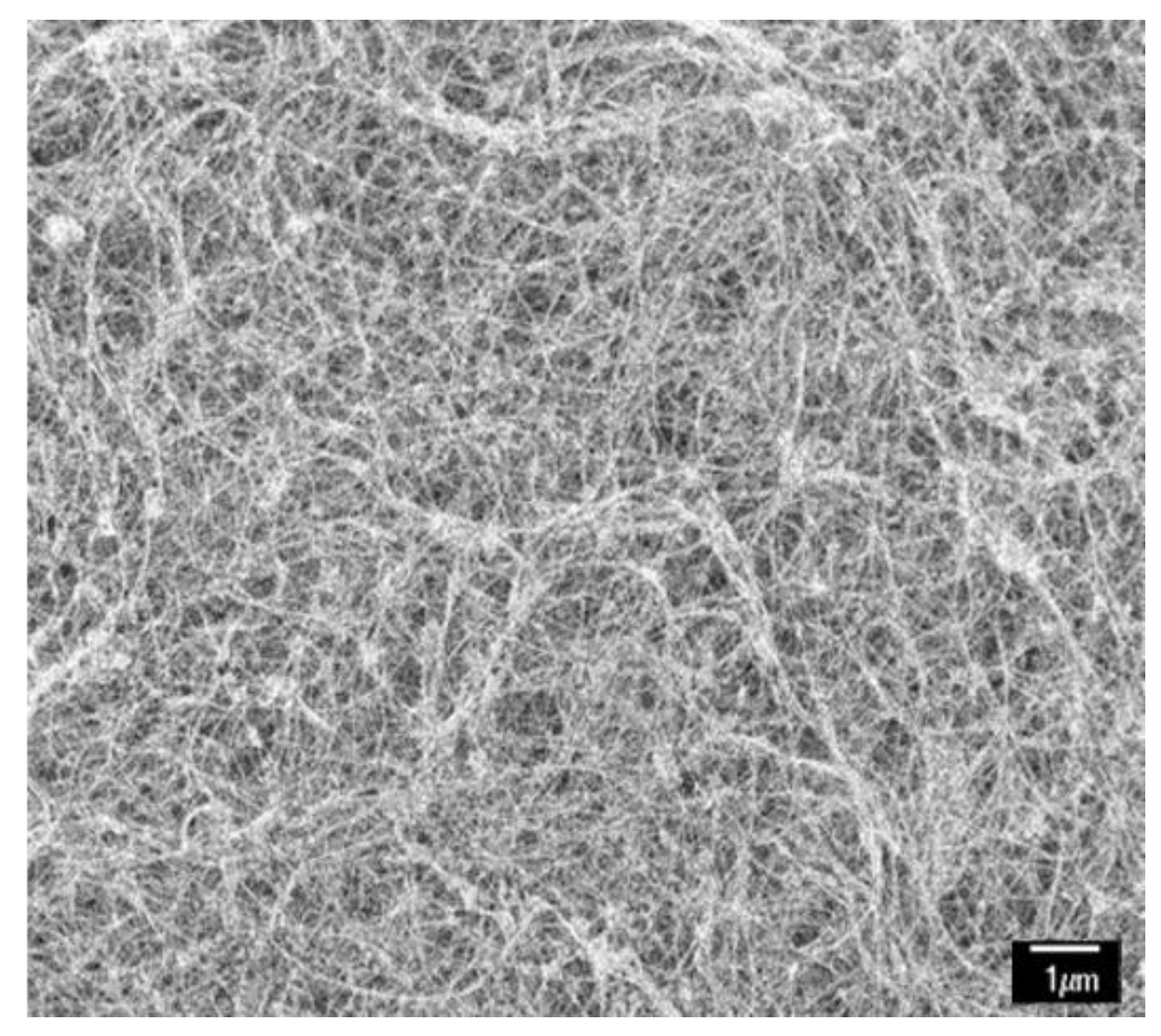
Buckypaper (NanoTechLab, Inc., Yadkinville, NC, USA) with 95% purity multi-wall CNTs was selected for our research. Its density was 0.3–0.4 and the average thickness was 0.05 mm. Figure 1 depicts an SEM image of the buckypaper.
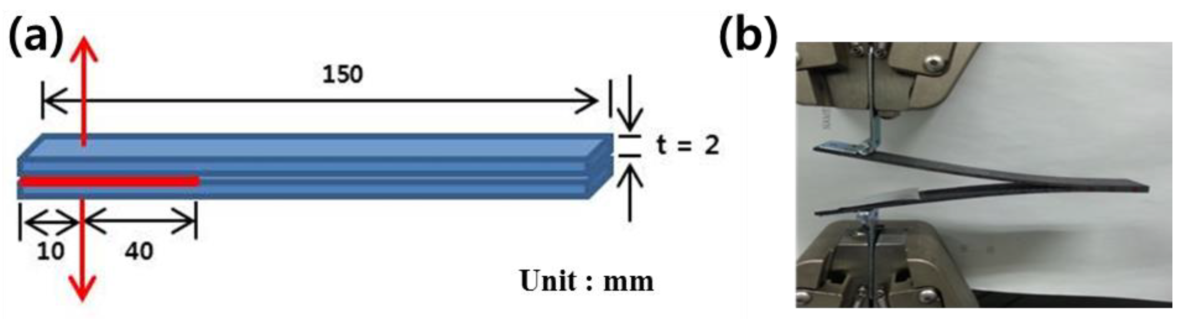
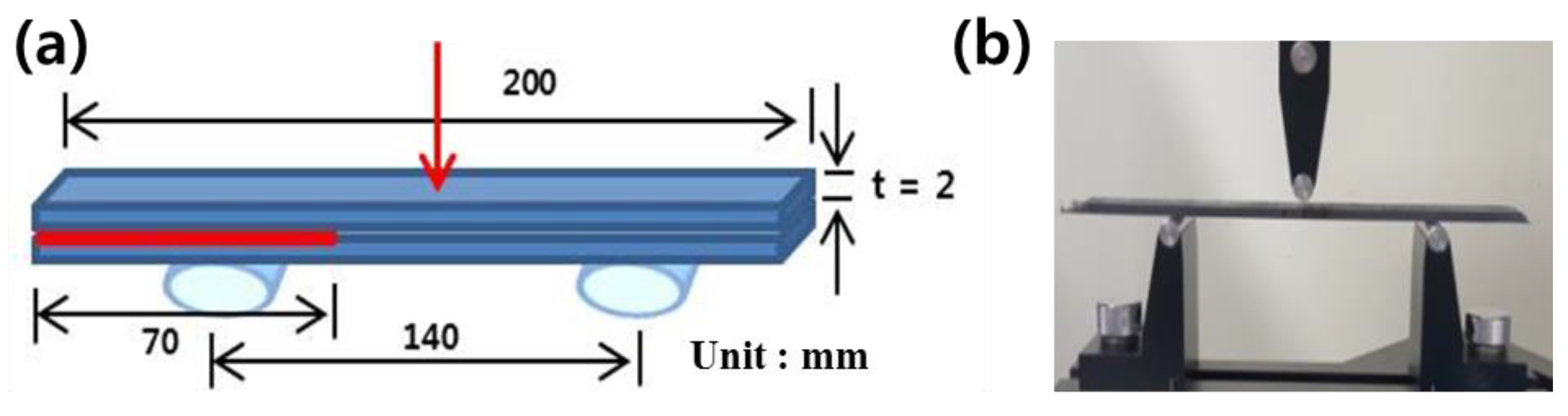
CFRP was fabricated using a woven carbon fiber prepreg (WSN3K, SK Chemical, WN) and unidirectional carbon fiber prepreg (USN200A, SK Chemical, UD) that had interleaved buckypaper. Carbon fibers in both prepregs were impregnated with epoxy resin in the b-stage state. The thicknesses of the woven carbon fiber prepreg and unidirectional prepreg ply were 0.23 mm and 0.205 mm, respectively. The epoxy resin contents of the prepreg plies were 40% and 36%, respectively. The in-plane shear strength and modulus were measured using woven carbon fiber prepreg specimens because the in-plane shear response of the polymer matrix composite in ASTM D 3518 was based on ±45° lamination. Four plies of woven carbon fiber prepregs were laminated and the interleaving films were placed between the 1st and 2nd, 2nd and 3rd, and 3rd and 4th plies. The specimen was cured using hot pressing at 140 °C for 1.5 h. The specimen’s dimensions were 130 × 10 × 0.9 . Interlaminar fracture toughness tests were conducted using a woven carbon fiber prepreg and unidirectional carbon fiber prepreg. For the mode I interlaminar fracture toughness test, both of the prepregs were fabricated with dimensions of 150 × 20 × 4 . For the middle ply of the laminates, a 50 mm long and 25 μm thick polytetrafluoroethylene (PTFE) film was inserted to initiate crack propagation. In the specimens with buckypaper interleaving, a 100 mm long buckypaper was placed behind the PTFE film. The lay-up was compacted using a roller. Piano hinges with a width of 20 mm were attached using an adhesive film (AF-163-2K, 3M, Two Harbors, MN, USA). For the mode II interlaminar fracture toughness test specimens, a 70 mm long and 25 μm thick PTFE film was placed as the middle ply of the laminates to initiate crack propagation. The dimensions of the laminates for the mode II tests were 200 × 20 × 4 . Figure 2 and Figure 3 illustrate the experimental setup for the mode I and mode II interlaminar fracture toughness tests, respectively. All measurements were performed using a universal testing machine (LR50K, Lloyd Instrument Ltd., Bognor Regis, UK). In-plane shear properties and mode II measurements were conducted using a 5 kN load cell; mode I measurements were conducted using a 1 kN load cell.
2.2. In-Plane Shear Property Measurement
Strain data were exported from a 2-axis strain gauge (KFG-2-120-D-16-11, KYOWA, Japan) and a data logger (SDL-350R, RADIAN, South Korea). The test was conducted in accordance with ASTM D3518 [23]. The shear stress of the ±45°-laminated specimen is given by Equation (1):
where denotes the applied tensile force and A denotes the cross-sectional area of the specimen. The engineering shear strain (the ratio of total deformation to the initial dimension of the specimen) is represented by Equation (2):
where denotes the longitudinal strain and denotes the transverse strain of the specimen. The shear modulus can be derived from the shear stress and shear strain from Equations (1) and (2), respectively:
According to the ASTM standard, should be between 2000 and 6000 .
2.3. Mode I Interlaminar Fracture Toughness Measurement
Each specimen was tested until the crack in the specimen was propagated to 130 mm. To measure the fracture toughness with respect to the delamination length, the crack was measured using a USB microscope after drawing a scale of 1 mm intervals on the side of the specimen. The crosshead speed was 4 mm/min. Modified beam theory method using the double cantilever beam (DCB) specimen geometry is represented by Equation (4):
where denotes the load, denotes the load point displacement, denotes the delamination length, and denotes the specimen width. Equation (4) could overestimate the value of fracture toughness. This was because the beam used for the test was not perfectly built (i.e., rotation occurred during delamination). One way to eliminate this problem is to use DCB specimens with longer delaminations with length , where may be determined experimentally by generating a least-squares plot of the cube root of the compliance. Equation (5) represents the modified compliance calibration method used to measure the mode I interlaminar fracture toughness [24]:
where denotes the slope of with respect to , and denotes the thickness of the specimen. Compliance, C, is the ratio of the load point displacement to the applied load .
2.4. Mode II Interlaminar Fracture Toughness Measurement
End notch flexure (ENF) tests were conducted to evaluate the mode II interlaminar fracture toughness. A compressive load was applied at the midpoint of the specimen. The crosshead speed for the test was . We calculated the mode II interlaminar fracture toughness using the ENF compliance expression given by Russel and Street [25]:
where P denotes the load, denotes the deflection of the loading point, denotes the span, denotes the crack length, denotes the effective bending modulus in the axial direction, B denotes the specimen width, and denotes half of the thickness of the specimen. The energy release rate can be explained based on the linear elastic fracture mechanics as follows:
From Equations (6) and (7), can be calculated using the following equation:
where denotes the critical load at the crack growth initialization. By substituting Equation (6) into Equation (8), can be expressed as follows:
where denotes the critical deflection value at the loading point.
3. Results and Discussion
3.1. In-Plane Shear Properties
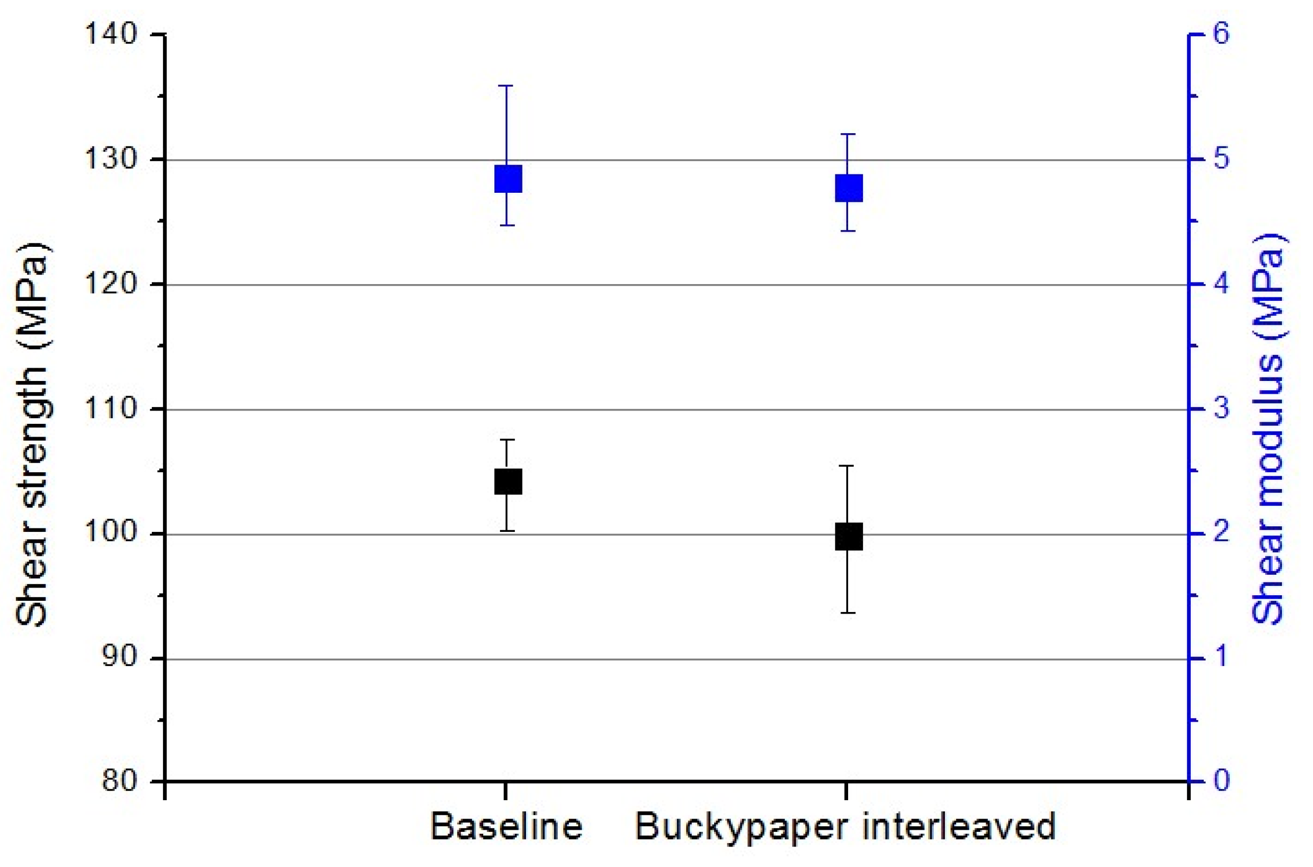
According to a few studies, interleaving increases the toughness but decreases the in-plane modulus and strength of the CFRP composites [26,27]. Therefore, the in-plane modulus and strength of the buckypaper-interleaved CFRP specimens were examined. Figure 4 shows the in-plane shear moduli and strengths of the specimens. We observed a negligible difference in the in-plane shear modulus and strength between the baseline and buckypaper-interleaved specimens. The in-plane shear strength of the buckypaper-interleaved specimens was 4% lower than that of the baseline specimens. The in-plane shear modulus values of both the baseline and buckypaper-interleaved specimens were similar.
In general, the in-plane properties of the laminate composite decreased because the fiber volume fraction was reduced due to interleaving. This tendency became more pronounced as the thickness of the interleaved film increased to a certain level [28]. Although only one buckypaper was interleaved, the in-plane property was more sensitive to the fiber volume fraction than the interlaminar property. The in-plane shear strength was slightly lowered due to the increase in the resin-rich area. Therefore, a buckypaper with appropriate thickness and areal weight should be added to reduce the trade-off caused by the swelling of the interleaved film.
3.2. Interlaminar Fracture Toughness
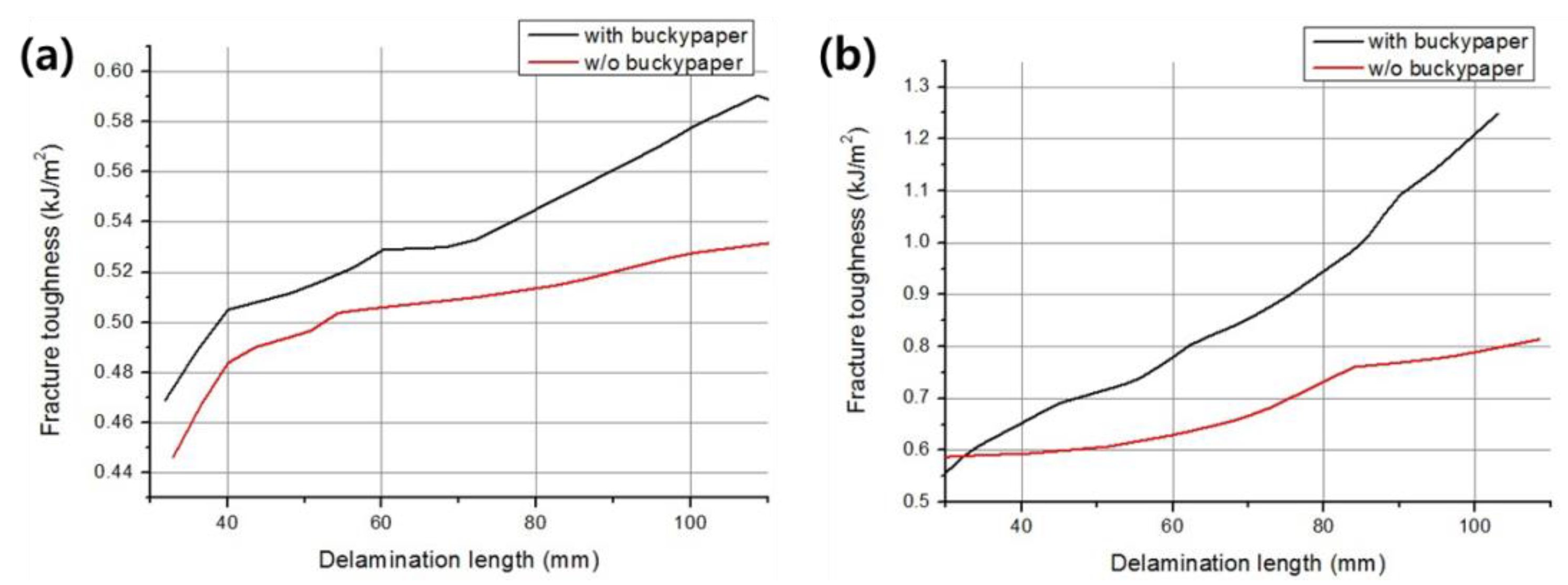
To characterize the initiation and propagation of the mode I delamination, G is represented by a function of the R curve (resistance curve) with respect to the delamination length. The test was conducted on each of the three unidirectional (UD) and woven (WN) specimens.
Figure 5 shows the average R curve of UD and WN with and without buckypaper interleaving. In both cases, the fracture toughness improved due to buckypaper interleaving. As depicted in Figure 5, the buckypaper-interleaved specimens exhibited a higher mode I interlaminar fracture toughness than those of the specimens without interleaving. The difference was noticeable in the woven carbon fiber prepreg specimens. ‘Rising’ R curve behavior was observed in both the unidirectional and woven carbon fiber prepreg specimens. In other words, the fracture energy increased steadily with an increase in crack length. Additionally, the difference in fracture toughness increased as the delamination progressed.
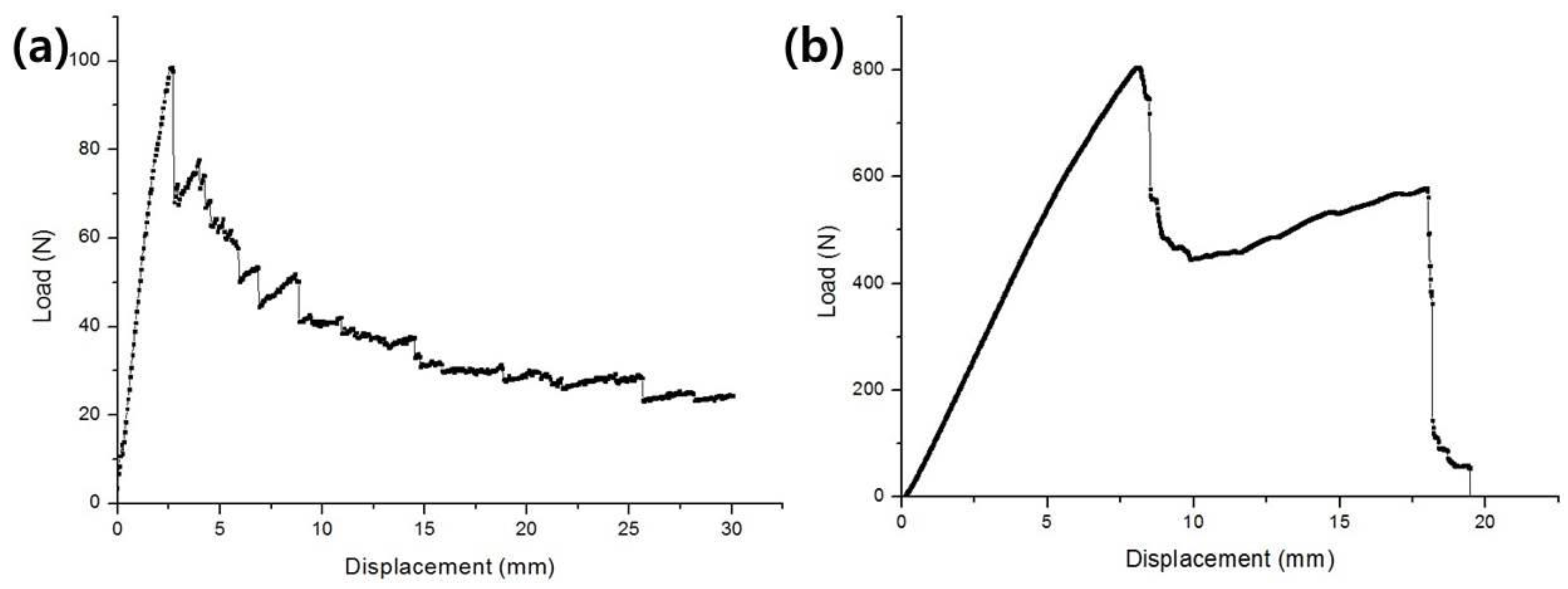
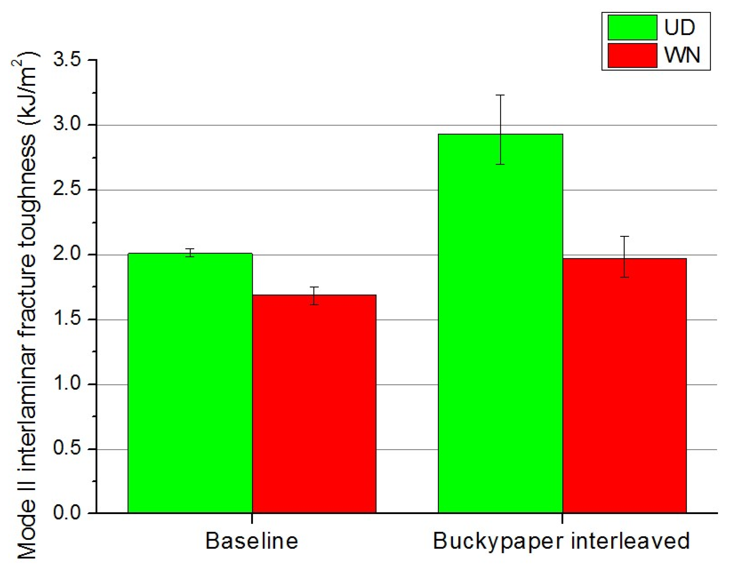
As shown in Figure 6, the mode II delamination had only two large load drops and significant crack propagation in contrast to the continuous delamination and load drop of the mode I delamination for a 200 mm long specimen. Figure 6a,b shows the typical load–displacement curves of WN and UD from the mode I and mode II tests of our research, respectively. This non-consecutive delamination process led to an error in the average value of the R curve. Therefore, Figure 7 shows the interlaminar fracture toughness at the critical load point for the mode II delamination. The values of the buckypaper-interleaved UD and WN specimens increased by 45.9% and 16.6%, respectively. A test was conducted for each of the five UD and WN specimens. The values of the WN laminates were lower than the values of the UD laminates because of their lower moduli and strengths. Thus, the results at a 90° or 45° orientation rather than at a 0° orientation of UD would be different.
3.3. Morphology
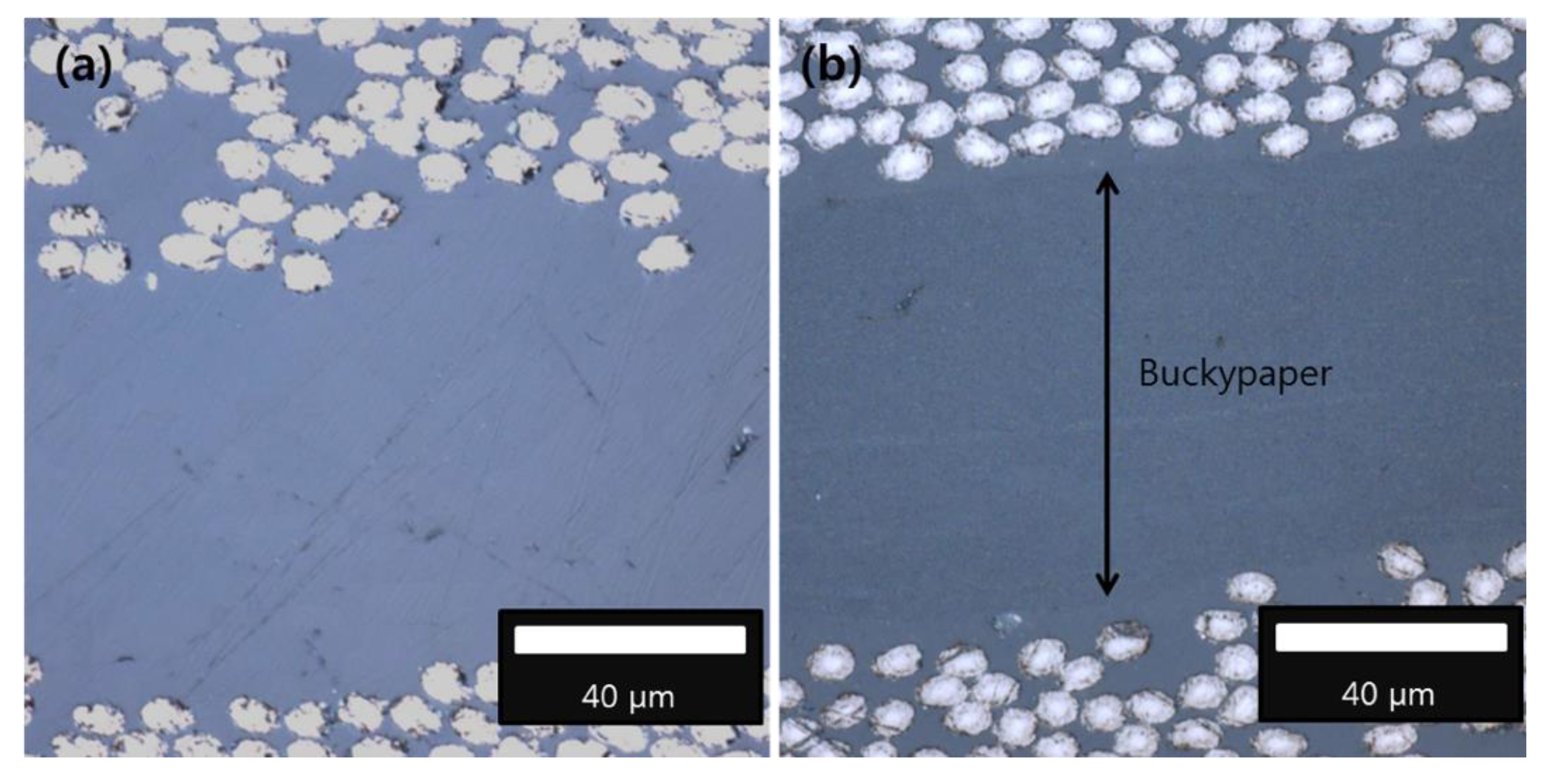
The morphology of the fractured surfaces of the specimens was analyzed to understand the toughening mechanism. Figure 8 shows the optical micrographs of the baseline and buckypaper-interleaved specimens. We observed that the buckypaper filled almost the entire resin-rich area, which was likely because of the roller compaction. As seen from Figure 8, the gap between the carbon fiber layers of the specimen containing buckypaper was approximately 10 μm larger than the gap between the carbon fiber layers of the specimen without buckypaper. In general, resin-rich composites exhibit a high interlaminar delamination toughness. The thick resin-rich interlaminar layer of composites allowed plastic deformation to extend over a larger volume than in high-fiber composites. However, the interlaminar fracture toughness of the buckypaper-interleaved composites was affected more by the CNT content and fiber–CNT interface than by the thickness of the interlaminar layer.
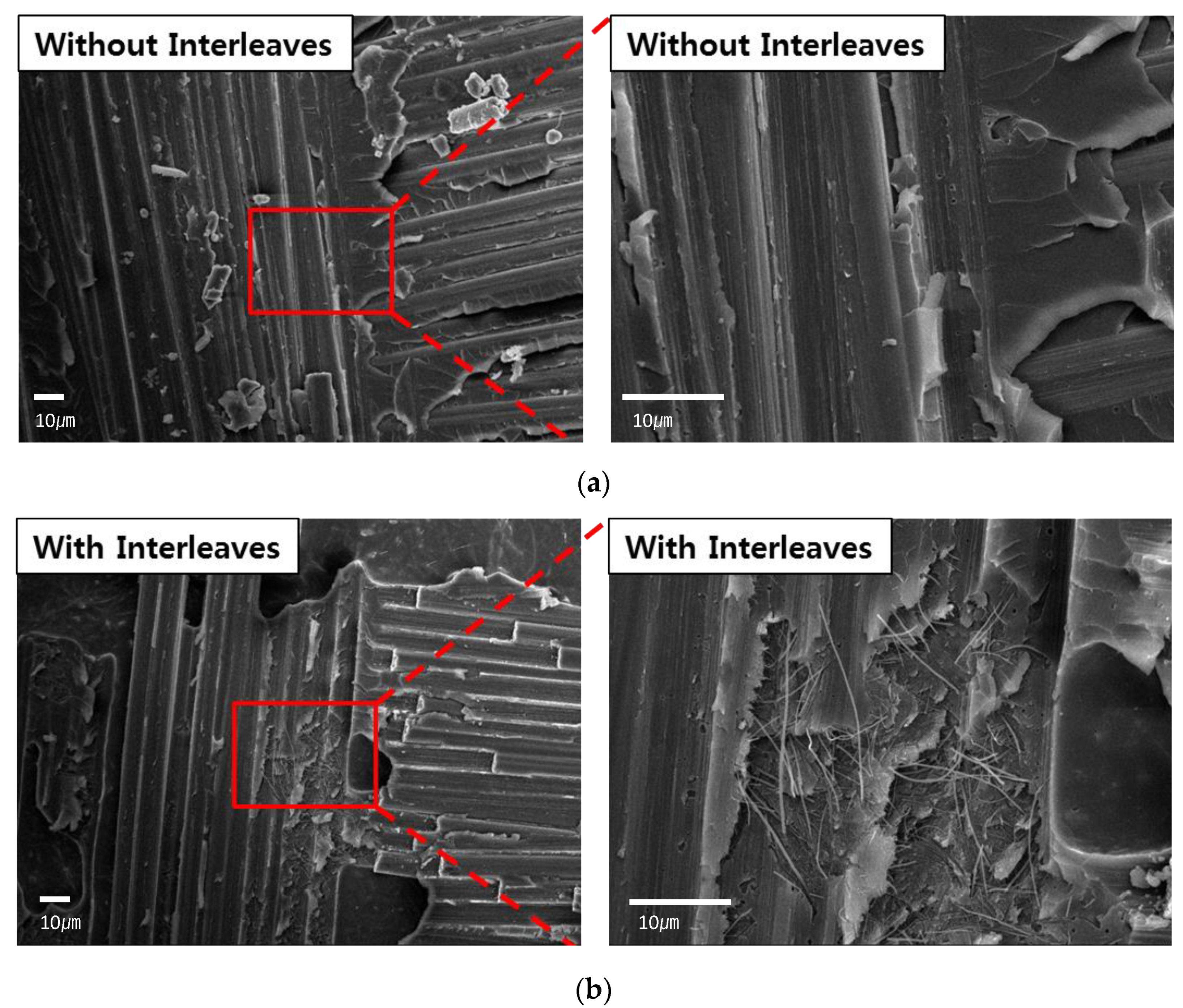
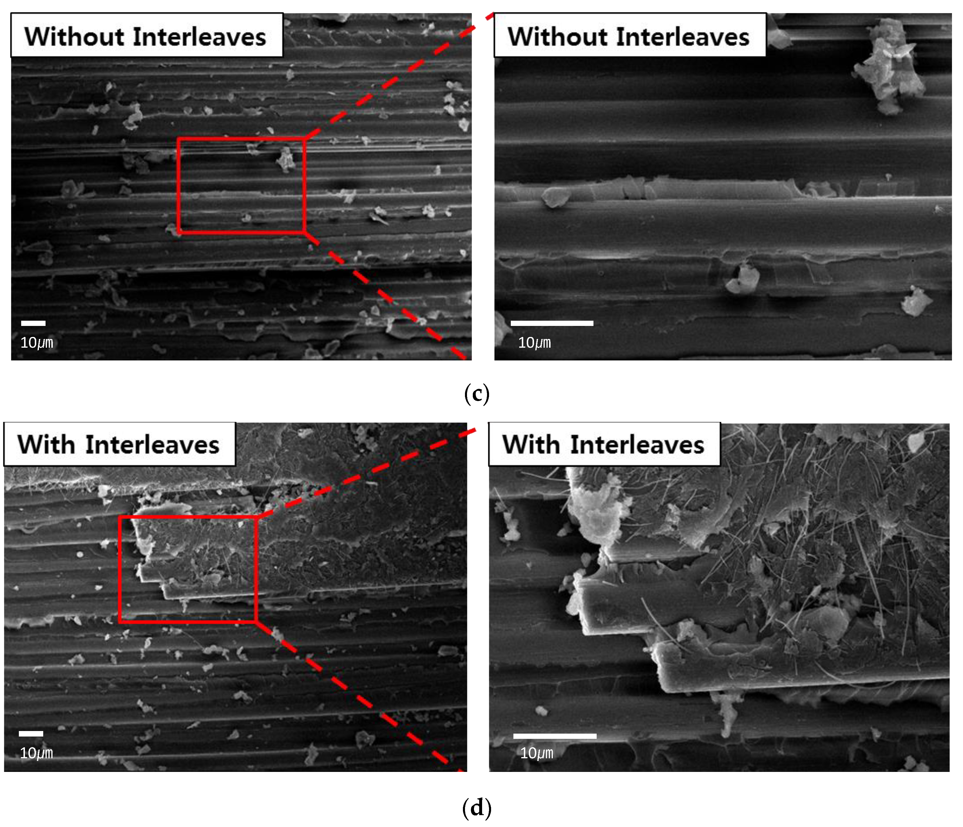
The toughening mechanisms of the specimens were investigated by examining the fracture surfaces from the mode I and mode II tests. The fracture surfaces of the tested specimens were cut into 10 × 10 samples for convenience in measurements. The samples were sputtered with platinum to avoid electron charging. SEM images of the fracture surface of the mode I delamination specimens are shown in Figure 9. The specimen observed in the SEM images depicted in Figure 9a,c are without buckypaper because the surface of the fibers was clean and did not have an attached matrix. Moreover, the fiber and matrix were separated in the baseline specimens. In other words, the baseline specimen had weak interfacial adhesion between the fiber and matrix, and debonding of the weak interfacial adhesion was the primary mode of failure for the specimen without buckypaper interleaving. In contrast, the fiber and matrix were attached after failure in the buckypaper-interleaved specimens, demonstrating strong interfacial adhesion, as shown in the SEM images depicted in Figure 9b,d. Moreover, the interlaminar failure for the specimen with buckypaper interleaving occurred due to fiber peeling and fiber breaking. Therefore, buckypaper interleaving modified the morphology of the interphase area of CFRP, leading to significant toughening. An increase in the mode I interlaminar fracture toughness was another application of CNT reinforcement using the same toughening mechanism as was used for buckypaper interleaving [29]. The fracture toughness of WN increased more than that of UD as the delamination length increased. This may have been due to the increase in the fracture surface area caused by the deflection of crack propagation by warp and weft, as well as the presence of CNTs in the surface area of the woven carbon fibers, as shown in Figure 9b.
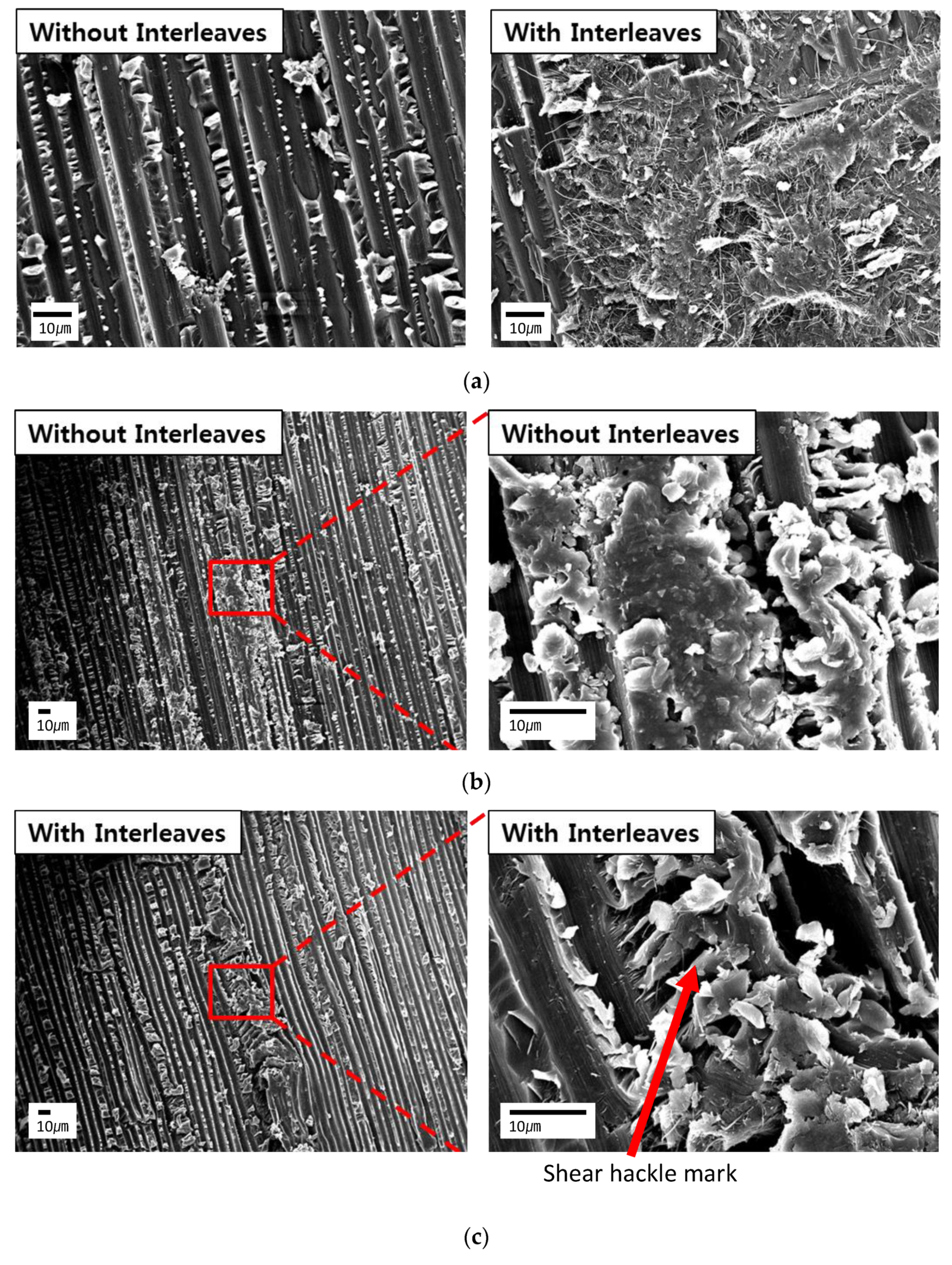
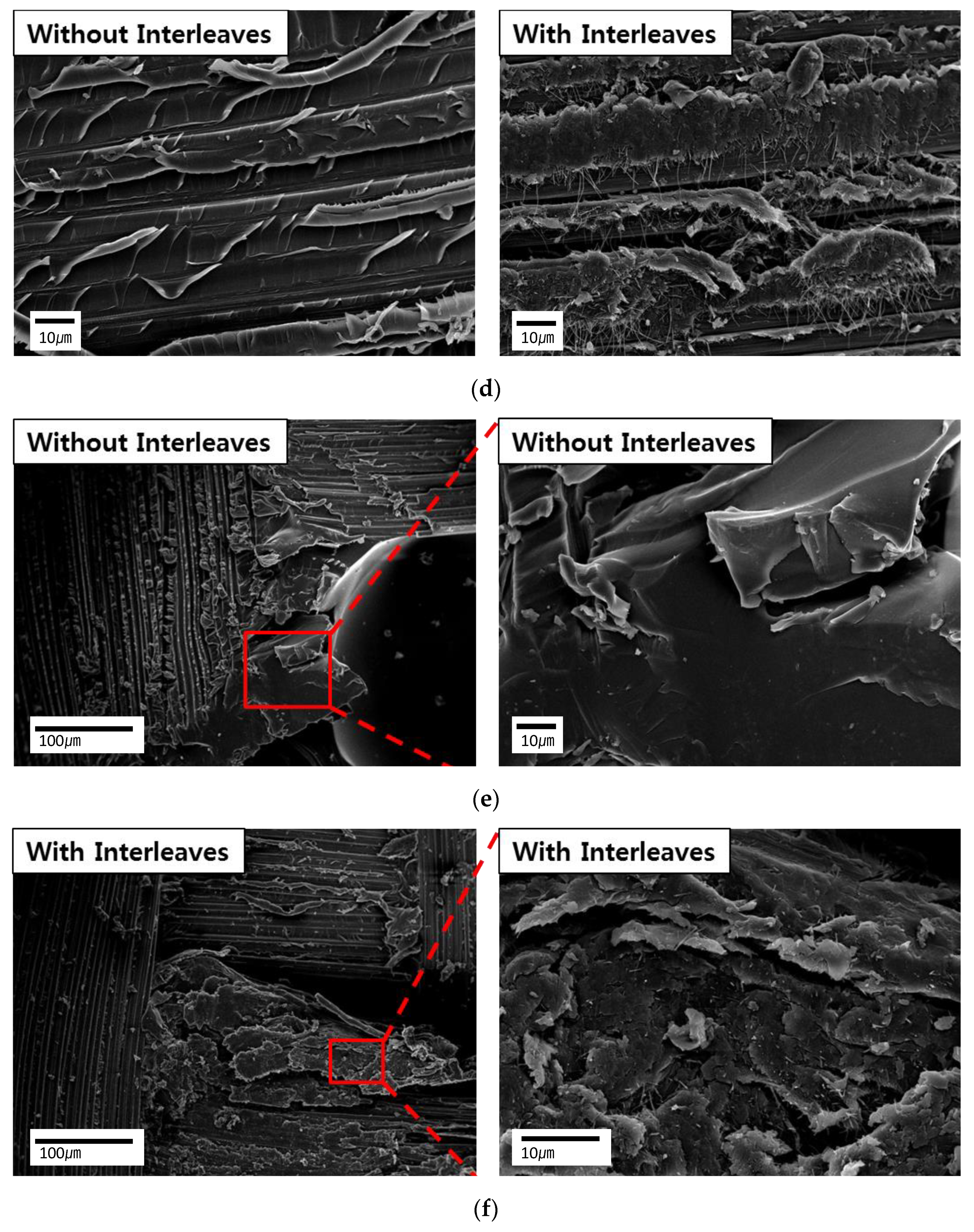
The fracture surfaces of the baseline and buckypaper-interleaved specimens from the ENF tests are shown in Figure 10. The SEM images in Figure 10a,d show that the fiber-matrix interface in the specimen with buckypaper interleaving was firmly attached after the fracture, as opposed to the interface in the baseline specimen. This indicates that strong interfacial adhesion and delamination occurred because of the CNT matrix in the interlayer. A major difference between the baseline and buckypaper-interleaved specimens was the amount of resin cover on the delaminated carbon fiber surface. The resin between the carbon fibers became rougher due to the presence of CNTs because of higher energy absorption during delamination [30]. Hackle marks (comb-like microcracks) due to shear fractures appeared prominently in the resin with numerous CNTs. As shown in Figure 10b, the baseline specimen surface without hackle marks was extremely smooth. In contrast, there were extensive shear hackle marks for the buckypaper-interleaved specimen, as shown in Figure 10c. The hackle marks were created due to crack deflection under a shear load because of the presence of CNTs.
The critical strain energy release rates in mode II (Figure 5 and Figure 7) were significantly higher than those in mode I. This was because the fracturing process zone in the mode II fracture was longer than that for the mode I fracture. Using a cohesive zone model, Xie et al. observed that the length of the mode II fracture process zone was approximately six times that of the mode I fracture process zone [31]. The longer process zone was accompanied by extensive hackle marks due to shear fractures containing numerous CNTs, which led to the toughening of CFRP composites [32]. In addition, CNTs increased the fracture toughness of the matrix in CFRP at the shear loading condition rather than at the opening loading condition.
In the case of WN, the warp and weft created a matrix-rich area. In the matrix-rich region, CNTs resisted matrix cracking via crack bridging. Moreover, the initiation and propagation of cracks required more of a load (Figure 10f). Therefore, interleaving buckypaper into CFRP enhanced the mode II fracture toughness.
4. Conclusions
The aim of our research was to increase the interlaminar fracture toughness and improve the physical properties of laminated carbon fiber composites. The CNT buckypaper was interleaved in CFRP laminates. The modes I and II interlaminar fracture toughnesses were measured using DCB and ENF tests, respectively. The in-plane shear modulus and strength were measured to investigate the effect of interleaving on the in-plane mechanical properties. The mode I and mode II interlaminar fracture toughnesses increased by interleaving the CNT buckypaper in both the UD and WN specimens. The in-plane shear properties decreased marginally due to the CNT buckypaper interleaving. The CNT-based interlaminar fracture toughening mechanism was studied by examining the fracture surfaces of various specimens using SEM and optical microscopy.
Author Contributions
Conceptualization, Y.-C.S.; methodology, Y.-C.S.; validation, Y.-C.S. and S.-M.K.; formal analysis, Y.-C.S. and S.-M.K.; investigation, Y.-C.S.; resources, S.-M.K.; data curation, Y.-C.S.; writing-original draft preparation, Y.-C.S.; writing-review and editing, S.-M.K.; visualization, Y.-C.S.; supervision, S.-M.K.; project administration, S.-M.K.; funding acquisition, S.-M.K.; All authors have read and agreed to the published version of the manuscript.
Funding
This work was supported by the Technology Innovation Program (20013958) funded by the Ministry of Trade, Industry and Energy (MOTIE, Korea).
Institutional Review Board Statement
Not applicable.
Informed Consent Statement
Not applicable.
Data Availability Statement
Not applicable.
Conflicts of Interest
The authors declare no conflict of interest.
References
- Joshi, S.C.; Dikshit, V. Enhancing interlaminar fracture characteristics of woven CFRP prepreg composites through CNT dispersion. J. Compos. Mater. 2012, 46, 665–675. [Google Scholar] [CrossRef]
- Gojny, F.H.; Wichmann, M.H.G.; Kopke, U.; Fiedler, B.; Schulte, K. Carbon nanotube-reinforced epoxy-compo sites: Enhanced stiffness and fracture toughness at low nanotube content. Compos. Sci. Technol. 2004, 64, 2363–2371. [Google Scholar] [CrossRef]
- Sihn, S.; Kim, R.Y.; Huh, W.; Lee, K.H.; Roy, A.K. Improvement of damage resistance in laminated composites with electrospun nano-interlayers. Compos. Sci. Technol. 2008, 68, 673–683. [Google Scholar] [CrossRef]
- Shay Hamer, H.L.; Anthony Green, R.I.; Ron Avrahami, E.Z.; Arnon Siegmann, D.S. Mode I Interlaminar Fracture Toughness of Nylon 66 Nanofibrilmat Interleaved Carbon/Epoxy Laminates. Polym. Compos. 2011, 32, 1781–1789. [Google Scholar] [CrossRef]
- Beylergil, B.; Tanoğlu, M.; Aktaş, E. Enhancement of interlaminar fracture toughness of carbon fiber-epoxy composites using polyamide-6,6 electrospun nanofibers. J. Appl. Polym. Sci. 2017, 134, 45244. [Google Scholar] [CrossRef]
- Shivakumar, K.; Lingaiah, S.; Chen, H.C.; Akangah, P.; Swaminathan, G.; Russell, L. Polymer Nanofabric Interleaved Composite Laminates. AIAA J. 2009, 47, 1723–1729. [Google Scholar] [CrossRef]
- Aksoy, A.; Carlsson, L.A. Interlaminar Shear Fracture of Interleaved Graphite Epoxy Composites. Compos. Sci. Technol. 1992, 43, 55–69. [Google Scholar] [CrossRef]
- Chen, L.; Wu, L.; Jiang, Q.; Tian, D.; Zhong, Z.; Wang, Y.; Fu, H. Improving Interlaminar Fracture Toughness and Impact Performance of Carbon Fiber/Epoxy Laminated Composite by Using Thermoplastic Fibers. Molecules 2019, 24, 3367. [Google Scholar] [CrossRef] [PubMed] [Green Version]
- Quan, D.; Bologna, F.; Scarselli, G.; Ivankovic, A.; Murphy, N. Interlaminar fracture toughness of aerospace-grade carbon fibre reinforced plastics interleaved with thermoplastic veils. Compos. Part A Appl. Sci. Manuf. 2020, 128, 105642. [Google Scholar] [CrossRef]
- Xu, F.; Yang, B.; Feng, L.; Huang, D.; Xia, M. Improved Interlaminar Fracture Toughness and Electrical Conductivity of CFRPs with Non-Woven Carbon Tissue Interleaves Composed of Fibers with Different Lengths. Polymers 2020, 12, 803. [Google Scholar] [CrossRef] [Green Version]
- Zhou, Y.X.; Wu, P.X.; Cheng, Z.Y.; Ingram, J.; Jeelani, S. Improvement in electrical, thermal and mechanical properties of epoxy by filling carbon nanotube. Express Polym. Lett. 2008, 2, 40–48. [Google Scholar] [CrossRef]
- Du, J.H.; Bai, J.; Cheng, H.M. The present status and key problems of carbon nanotube based polymer composites. Express Polym. Lett. 2007, 1, 253–273. [Google Scholar] [CrossRef]
- Ganguli, S.; Bhuyan, M.; Allie, L.; Aglan, H. Effect of multi-walled carbon nanotube reinforcement on the fracture behavior of a tetrafunctional epoxy. J. Mater. Sci. 2005, 40, 3593–3595. [Google Scholar] [CrossRef]
- Coleman, J.N.; Khan, U.; Blau, W.J.; Gun’ko, Y.K. Small but strong: A review of the mechanical properties of carbon nanotube-polymer composites. Carbon 2006, 44, 1624–1652. [Google Scholar] [CrossRef]
- Tjong, S.C. Structural and mechanical properties of polymer nanocomposites. Mater. Sci. Eng. R. 2006, 53, 73–197. [Google Scholar] [CrossRef]
- Xie, X.L.; Mai, Y.W.; Zhou, X.P. Dispersion and alignment of carbon nanotubes in polymer matrix: A review. Mater. Sci. Eng. R. 2005, 49, 89–112. [Google Scholar] [CrossRef]
- Thostenson, E.T.; Li, W.Z.; Wang, D.Z.; Ren, Z.F.; Chou, T.W. Carbon nanotube/carbon fiber hybrid multiscale composites. J. Appl. Phys. 2002, 91, 6034–6037. [Google Scholar] [CrossRef]
- Garcia, E.J.; Wardle, B.L.; Hart, A.J. Joining prepreg composite interfaces with aligned carbon nanotubes. Compos. Part A Appl. Sci. Manuf. 2008, 39, 1065–1070. [Google Scholar] [CrossRef]
- Shin, Y.C.; Lee, W.I.; Kim, H.S. Mode II interlaminar fracture toughness of carbon nanotubes/epoxy film-interleaved carbon fiber composites. Compos. Struct. 2020, 236, 111808. [Google Scholar] [CrossRef]
- Bilge, K.; Ozden-Yenigun, E.; Simsek, E.; Menceloglu, Y.Z.; Papila, M. Structural composites hybridized with epoxy compatible polymer/MWCNT nanofibrous interlayers. Compos. Sci. Technol. 2012, 72, 1639–1645. [Google Scholar] [CrossRef]
- Rodríguez-González, J.; Rubio-González, C. Mixed-mode I/II interlaminar fracture toughness of carbon fiber/epoxy composites with the addition of multiwalled carbon nanotubes by spraying technique. J. Compos. Mater. 2018, 52, 3045–3052. [Google Scholar] [CrossRef]
- Ou, Y.; González, C.; Vilatela, J. Interlaminar toughening in structural carbon fiber/epoxy composites interleaved with carbon nanotube veils. Compos. Part A Appl. Sci. Manuf. 2019, 124, 105477. [Google Scholar] [CrossRef] [Green Version]
- ASTM Standard D3518. Standard Test Method for In-Plane Shear Response of Polymer Matrix Composite Materials by Tensile Test of a ±450 Laminate; ASTM International: West Conshohocken, PA, USA, 2007. [Google Scholar]
- ASTM Standard D5528. Standard Test Method for Mode I Interlaminar Fracture Toughness of Unidirectional Fiber-Reinforced Polymer Matrix Composites; ASTM International: West Conshohocken, PA, USA, 2007. [Google Scholar]
- Russell, A.J. Factors Affecting the Interlaminar Fracture Energy of Graphite/Epoxy Laminates. In Proceeding of the ICCM-IV, Tokyo, Japan, 25–28 October 1982. [Google Scholar]
- Sun, C.T.; Norman, T.L. Design of a Laminated Composite with Controlled-Damage Concept. Compos. Sci. Technol. 1990, 39, 327–340. [Google Scholar] [CrossRef]
- Norman, T.L.; Sun, C.T. Mechanical-Properties and Interlaminar Toughness of Cross-Plied Laminates Containing Adhesive Strips. AIAA J. 1991, 29, 247–252. [Google Scholar] [CrossRef]
- Kim, J.W.; Lee, J.S. Influence of Interleaved Films on the Mechanical Properties of Carbon Fiber Fabric/Polypropylene Thermoplastic Composites. Materials 2016, 9, 344. [Google Scholar] [CrossRef]
- Truong, G.T.; Choi, K.K. Effect of short multi-walled carbon nanotubes on the mode I fracture toughness of woven carbon fiber reinforced polymer composites. Constr. Build. Mater. 2020, 259, 119696. [Google Scholar] [CrossRef]
- Khan, S.U.; Kim, J.-K. Improved interlaminar shear properties of multiscale carbon fiber composites with bucky paper interleaves made from carbon nanofibers. Carbon 2012, 50, 5265–5277. [Google Scholar] [CrossRef]
- Xie, J.W.; Waas, A.M.; Rassaian, M. Estimating the process zone length of fracture tests used in characterizing composites. Int. J. Solids Struct. 2016, 100, 111–126. [Google Scholar] [CrossRef]
- Quan, D.; Urdaniz, J.L.; Ivankovic, A. Enhancing mode-I and mode-II fracture toughness of epoxy and carbon fibre reinforced epoxy composites using multi-walled carbon nanotubes. Mater. Des. 2018, 143, 81–92. [Google Scholar] [CrossRef]
Figure 1.
SEM image of the buckypaper.

Figure 2.
Mode I interlaminar fracture toughness test: (a) specimen dimension and (b) test setup.

Figure 3.
Mode II interlaminar fracture toughness test: (a) specimen dimension and (b) test setup.

Figure 4.
In-plane shear strength (black) and shear modulus (blue).

Figure 5.
R curve of mode I delamination: (a) UD and (b) WN.

Figure 6.
Load–displacement curves from the delamination test: (a) mode I and (b) mode II.

Figure 7.
of UD and WN.

Figure 8.
Optical micrographs of cross-sections of the (a) baseline specimen and (b) buckypaper-interleaved specimen.
Figure 8.
Optical micrographs of cross-sections of the (a) baseline specimen and (b) buckypaper-interleaved specimen.

Figure 9.
SEM images of the fracture surface of the mode I test specimens: (a) WN baseline, (b) WN interleaved with buckypaper, (c) UD baseline, and (d) UD interleaved with buckypaper.
Figure 9.
SEM images of the fracture surface of the mode I test specimens: (a) WN baseline, (b) WN interleaved with buckypaper, (c) UD baseline, and (d) UD interleaved with buckypaper.


Figure 10.
SEM images of the fracture surface of the mode II test specimens: (a) UD baseline (left) and UD interleaved with buckypaper (right), (b) UD baseline, (c) UD interleaved with buckypaper, (d) WN baseline (left) and WN interleaved with buckypaper (right), (e) WN baseline resin-rich area, and (f) WN buckypaper-interleaved resin-rich area.


Publisher’s Note: MDPI stays neutral with regard to jurisdictional claims in published maps and institutional affiliations. |
© 2021 by the authors. Licensee MDPI, Basel, Switzerland. This article is an open access article distributed under the terms and conditions of the Creative Commons Attribution (CC BY) license (https://creativecommons.org/licenses/by/4.0/).
Share and Cite
MDPI and ACS Style
Shin, Y.-C.; Kim, S.-M. Enhancement of the Interlaminar Fracture Toughness of a Carbon-Fiber-Reinforced Polymer Using Interleaved Carbon Nanotube Buckypaper. Appl. Sci. 2021, 11, 6821. https://doi.org/10.3390/app11156821
AMA Style
Shin Y-C, Kim S-M. Enhancement of the Interlaminar Fracture Toughness of a Carbon-Fiber-Reinforced Polymer Using Interleaved Carbon Nanotube Buckypaper. Applied Sciences. 2021; 11(15):6821. https://doi.org/10.3390/app11156821
Chicago/Turabian StyleShin, Yong-Chul, and Seung-Mo Kim. 2021. "Enhancement of the Interlaminar Fracture Toughness of a Carbon-Fiber-Reinforced Polymer Using Interleaved Carbon Nanotube Buckypaper" Applied Sciences 11, no. 15: 6821. https://doi.org/10.3390/app11156821
Note that from the first issue of 2016, this journal uses article numbers instead of page numbers. See further details here.