
Axial Compressive Performance of a Composite Concrete-Filled GFRP Tube Square Column

College of Civil Engineering, Nanjing Tech University, Nanjing 211816, China
*
Author to whom correspondence should be addressed.
Appl. Sci. 2021, 11(15), 6757; https://doi.org/10.3390/app11156757
Submission received: 27 June 2021
/
Revised: 17 July 2021
/
Accepted: 19 July 2021
/
Published: 23 July 2021
(This article belongs to the Special Issue Numerical Modeling and Mechanical Properties Analysis for Building Materials)
Abstract
:Featured Application
A new type of composite column was introduced, the adoption of proper GFRP layers and strip intervals not only facilitates convenient construction, but also ensures that the bearing capacity of the composite column and that the material properties of GFRP are fully utilized.
Abstract
A composite concrete-filled glass fiber reinforced polymer (GFRP) tube square column is a new type of composite column, where GFRP is externally wrapped over several GFRP square tubes to form a multicavity GFRP tube, and then concrete is poured inside. External GFRP wrapping methods can be divided into two types: entirely wrapped and strip-type wrapped methods. The former is superior to the latter in terms of performance under stress. However, difficulties are introduced in the construction process of the former, and substantial materials are required to wrap the entire structure. To examine the axial compressive performance for this new type of composite column and the impact of the wrapping method, we designed and fabricated one type of entirely wrapped composite column and two types of strip-type wrapped composite columns with clear spacings of 85 mm and 40 mm, respectively, and performed static axial compression tests. Through tests and numerical simulations, we obtained the failure mode, load–displacement curve, and load–strain curve of the specimen, and analyzed the impact of the externally wrapped GFRP on the mechanical behavior of the composite column. The results show that the composite column reached the peak load before the fracture of the GFRP tube fiber occurred, and the bearing capacity declined sharply to approximately 75% of the peak load after the fiber fractured, then entered a platform section, thereby displaying ductile failure. As the wrapped layers of GFRP strips increased, the load capacity of the specimen exhibited a linear growth tendency. Compared with the performance of the entirely wrapped method, the load capacity of the specimens in the W5040 group declined 9.8% on average, and the peak efficiency of the GFRP strips increased by 50%, thereby indicating that the use of appropriate GFRP layers and strip distance intervals can ensure the appropriate bearing capacity of composite columns and full utilization of GFRP material properties.
1. Introduction
Fiber-reinforced polymer (FRP) tubes, which are characterized by light weight, high strength, corrosion resistance, easy processing, and fatigue resistance, were first applied to military facilities in the US, and then to the construction field by British engineers [1,2]. An FRP-confined concrete column is a composite component formed by wrapping FRP on the outside of the concrete column. Under the action of axial loading, FRP has a confining effect on the internal concrete such that the composite column is in triaxial compression state, which improves the bearing capacity, second-order stiffness, and ductility of the component [3,4]. In addition, compared with the performance of concrete-filled steel tube columns, FRPs demonstrate good performance in withstanding seawater corrosion, and can effectively protect internal concrete and bars [5,6], thereby making them especially suitable for coastal and marine engineering applications. Additionally, FRP products are diverse, and can be implemented in sheets, FRP bars, etc., thereby meeting a variety of reinforcement requirements. Therefore, FRP products have quickly been employed in civil engineering applications for a variety of structural fields [7,8,9]. Cascardi led a research, consisting of an experimental and theoretical study focused on masonry columns with the discontinuous FRP-confinement. The results revealed the significant beneficial effects of FRP-confinement, in terms of increase in ultimate load and axial strain [10].
Pultruded FRP profiles are sophisticated industrial FRP products. The fibers are usually parallel to the length of the profile and are affected by the pultrusion process. As a result, a typical pultruded FRP tube exhibits excellent longitudinal strength but very undesirable lateral strength. Therefore, concrete cannot be filled within traditional pultruded FRP tubes to form FRP-confined concrete columns. In recent years, vast advances have been made in the pultrusion process based on multidirectional filaments. The pultruded profile, containing a 45° filament, exhibits mechanical behaviors that are different from those of a traditional pultruded profile in that the lateral tensile strength has been significantly improved [11,12], and it can provide greater lateral confinement for the internal concrete. The emergence of this new type of pultruded profile provides a new way to employ FRP-confined concrete columns [13].
Due to technological limitations, the sections of pultruded profiles that are currently used are relatively small, thereby making it difficult to directly apply these profiles to composite columns with a large section and large bearing capacity. To address this issue, glass fiber-reinforced polymer (GFRP) confined concrete-filled composite square columns were proposed in this study. Through the free combination of small section pultruded tubes, composite columns with a variety of section sizes could be formed to meet different engineering needs. The new column proposed in this paper originates from the FRP strips reinforced steel tube confining the concrete column. The use of pultruded GFRP tubing, instead of steel tubing, can improve the specimen’s corrosion resistance, which can be widely used in load-bearing components and sea–sand–concrete structures [14,15].
Structures such as beam-column nodes will unavoidably appear in practical engineering. FRP strips wrapped over a beam or column can achieve a good confinement effect. They have good application prospects as they allow flexible adjustment between the deformability and strength capacity, less consumption of FRP in engineering, and convenience in mechanical automated construction.
We conducted static axial compression tests on the designed GFRP-confined concrete composite square column, studied the interaction between the pultruded tube and concrete, and the confinement mechanism for the pultruded tube under axial compression loading, and revealed the law for the stress redistribution in the section and its impact on the confinement effect of the pultruded tube. Through the finite element software ABAQUS, we constructed a refined numerical analysis model that allows for the interaction between the built-in pultruded tube and the internal concrete, analyzed the impact of geometric parameters on the mechanical properties of the composite column, and compared simulation results with the test results. The finite element numerical model established in this study performs well in simulating the axial compression stress of the GFRP concrete composite column, and in analyzing the mechanical performance of the proposed composite column under axial compression loading.
2. Materials and Methods
2.1. Specimen Design and Fabrication
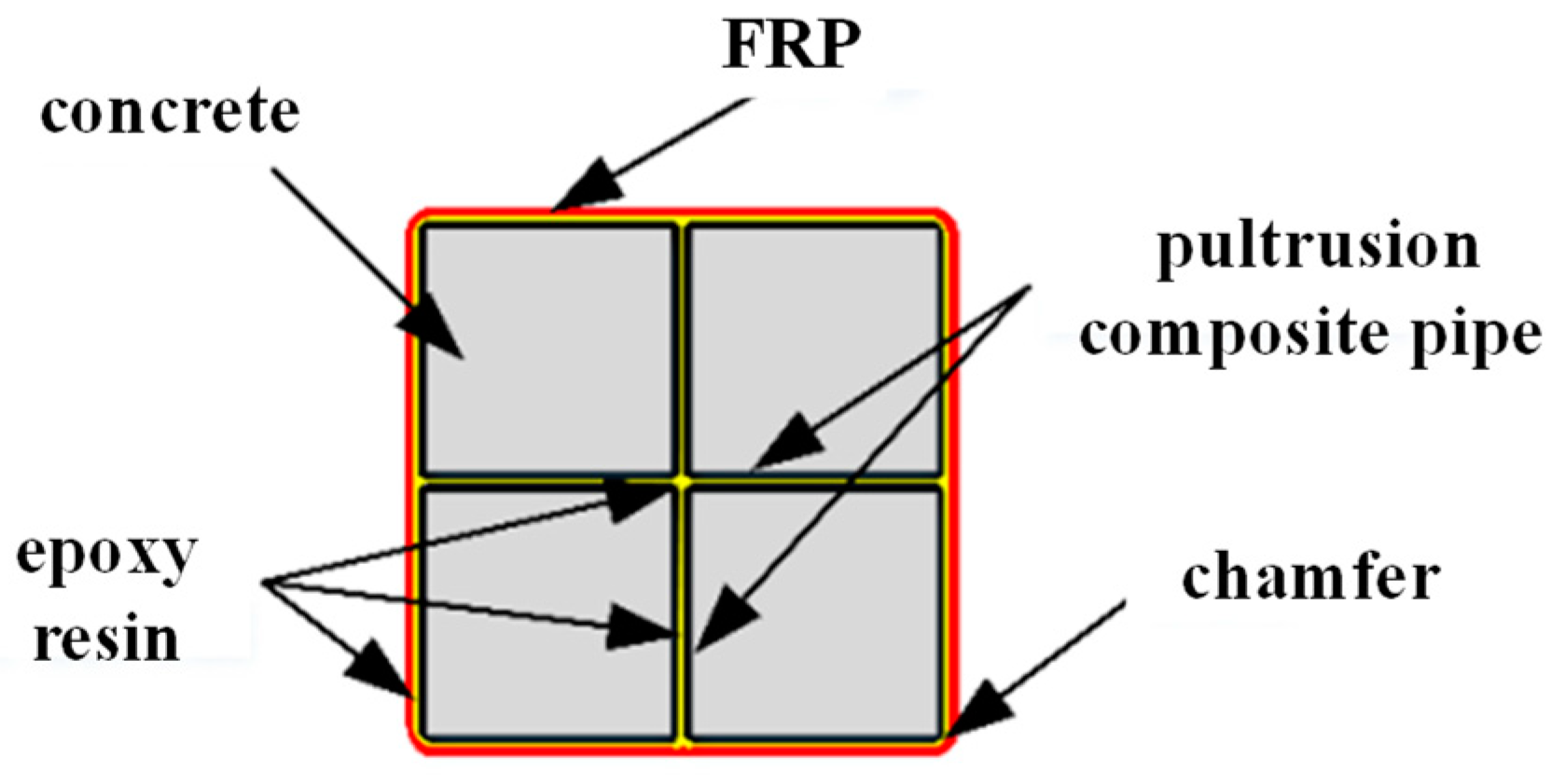
The composite square column used in the experiment was composed of 4 pultruded GFPR tubes. Resin (mixed with silica powder) was selected as the adhesive adopted for the splicing surface of the GFRP tubes. The GFRP was externally wrapped by the hand lay-up method, and the adhesive was epoxy resin. GFRP wrapping methods were divided into complete wrapping and strip-type wrapping. Four layers of GFRP were wrapped for each group of test specimens. To prevent damage at the ends of the specimen, two layers of GFRP strips with a width of 25 mm were wrapped around both ends of all the specimens for reinforcement. The overlap length is important, but it is not the test parameter in this paper. When wrapping GFRP strips, the overlap length is 200 mm [16]. The overlap position of GFRP strips with different interface heights is staggered to ensure the mechanical properties of the specimen. The composite concrete square column is shown in Figure 1.
In the experiment, 3 groups of 6 GFRP-confined composite concrete square short columns were fabricated. The section size of the composite column L × B was 204 mm × 204 mm, the height H of the specimen was 600 mm, and the wall thickness t of the pultruded tube was 5.25 mm. The composite column was wrapped with GFRP made of 4 layers of unidirectional glass fiber cloth, with a chamfer radius of R = 5 mm. W600S0 represents the continuously and entirely wrapped method. The other two groups were wrapped with GFRP strips with a width of 50 mm and clear spacings of 40 mm and 85 mm. The specific parameters of the specimens are shown in Table 1.
2.2. Material Properties
According to the test methods of ASTM D3039 and ASTM D3410 [17,18], the tensile strength and modulus of pultruded GFRP tubes and externally wrapped GFRP strips were measured, and the compression test of GFRP tubes was performed with reference to GB/T 5350-2005 [19]. The test was performed on the 400 kN MTS Insight Electromechanical Testing System, and the loading rate was 2 mm/min. The test results are shown in Table 2.
All the specimens were poured with the same batch of C30 concrete, and 150 mm × 150 mm × 150 mm concrete test cubes were reserved, which were tested in accordance with the Standard for Test Methods for the Mechanical Properties of Ordinary Concrete (GB/T 50081-2019) (2019) [20] to measure the compressive strength of concrete cubes. The test results are shown in Table 3.
2.3. Loading and Locations of the Strain Gauges
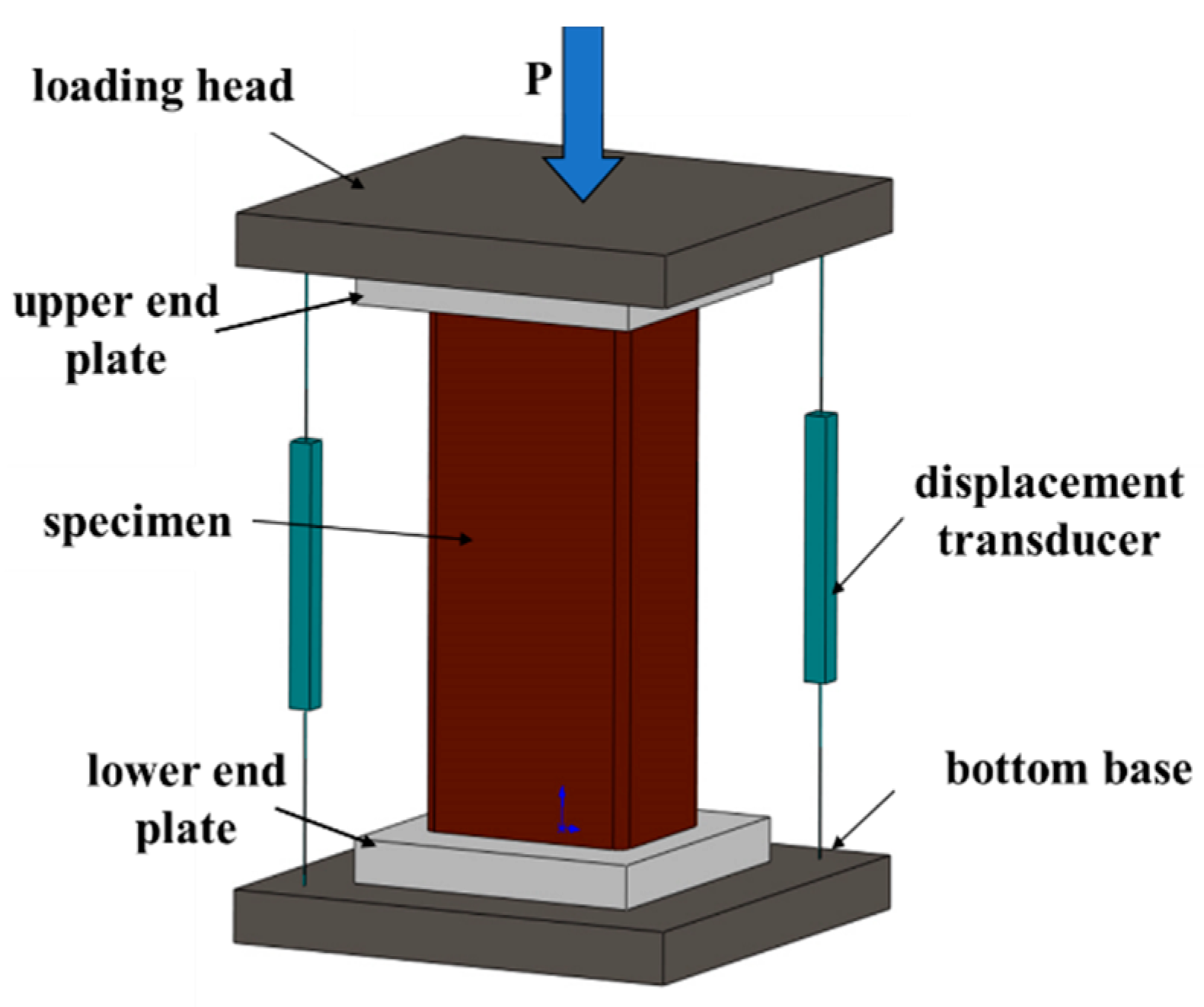
The static axial compression test was performed in the Composite Materials Laboratory of Nanjing Tech University. The test used a 500 t pressure testing machine, and the data acquisition system adopted a DH3818N static strain tester for data collection. A schematic diagram of the loading device is shown in Figure 2. The test adopted monotonic axial loading and displacement control, and the loading rate was 2 mm/min. Preloading was performed before formal loading. The preloading axial force was taken at 10% of the estimated ultimate load, which was used to eliminate the gap between the specimen and the loading device, and analyze the alignment of the specimen based on the linear variable differential transformer (LVDT) and strain gauge readings.
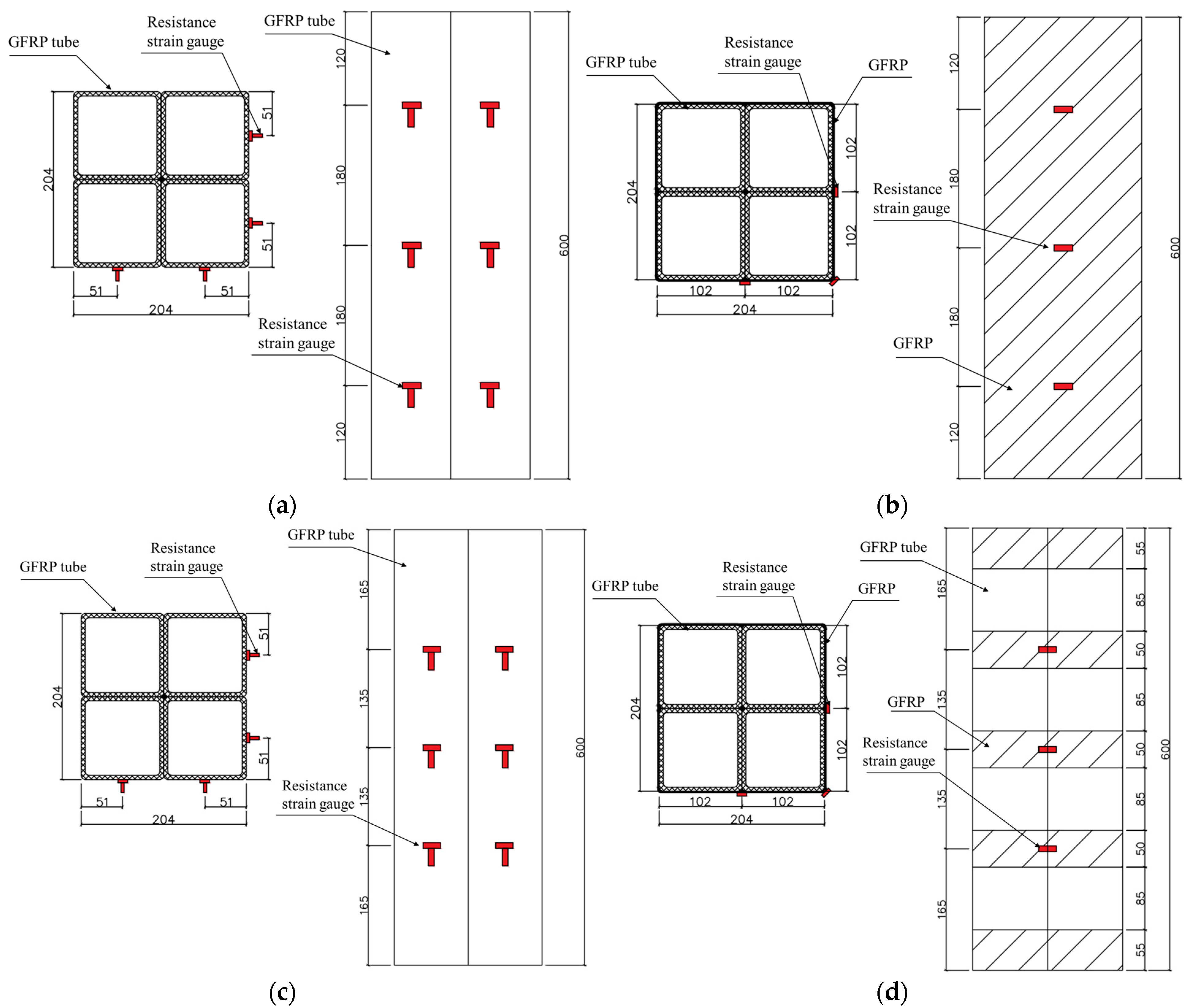
Location of the strain gauge is shown in Figure 3. The locations of the strain gauges for specimens W600S0 and W50S40 were the same (as shown in Figure 3a,b, with W600S0 as an example). Longitudinal and lateral strain gauges were installed at the middle of the GFRP tube and 120 mm away from the upper and lower ends, a lateral strain gauge was installed in the middle of the externally wrapped GFRP strips and 120 mm away from the upper/lower end, and another lateral strain gauge was installed on the corner of the same section. The locations of the strain gauges for specimen W50S85 are shown in Figure 3c,d. Longitudinal and lateral strain gauges were installed in the middle of the GFRP tube and 165 mm away from the upper/lower end, respectively. A lateral strain gauge was installed in the middle of the externally wrapped GFRP strips and 165 mm away from the upper/lower end, and a lateral strain gauge was installed at the corner of the same section.
3. Results
3.1. Test Phenomenon and Failure Mode
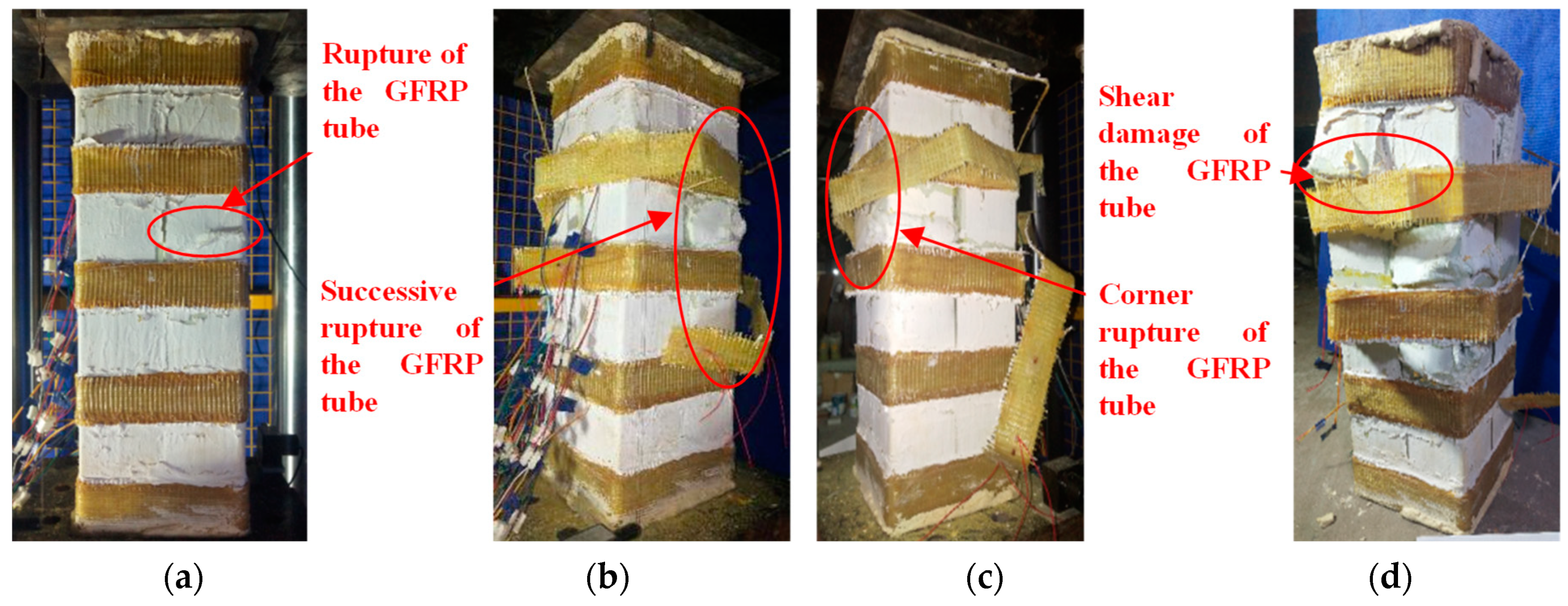
In the initial stage of loading for the axial compression test, the three sets of specimens were in the linear elastic stage, and no obvious test phenomenon was observed. The loading process was continued, and W50S85 is taken as an example. When the peak load was reached, the load plummeted to approximately 75% of the load capacity, a loud noise was heard, and the GFRP tube ruptured (Figure 4a). Then, loading continued further, and the GFRP tube bulged outward due to the expansion and squeezing of the internal concrete. With the increase in the displacement, the bulging area and extent of the GFRP tube expanded, the fiber cloth externally wrapped over the GFRP tube broke and failed (Figure 4b), and the corner of the GFRP tube ruptured (Figure 4c). Loading continued. The GFRP tube underwent shear failure along the edge of the externally wrapped GFRP strips. The failure mode of the specimen is shown in Figure 4d.
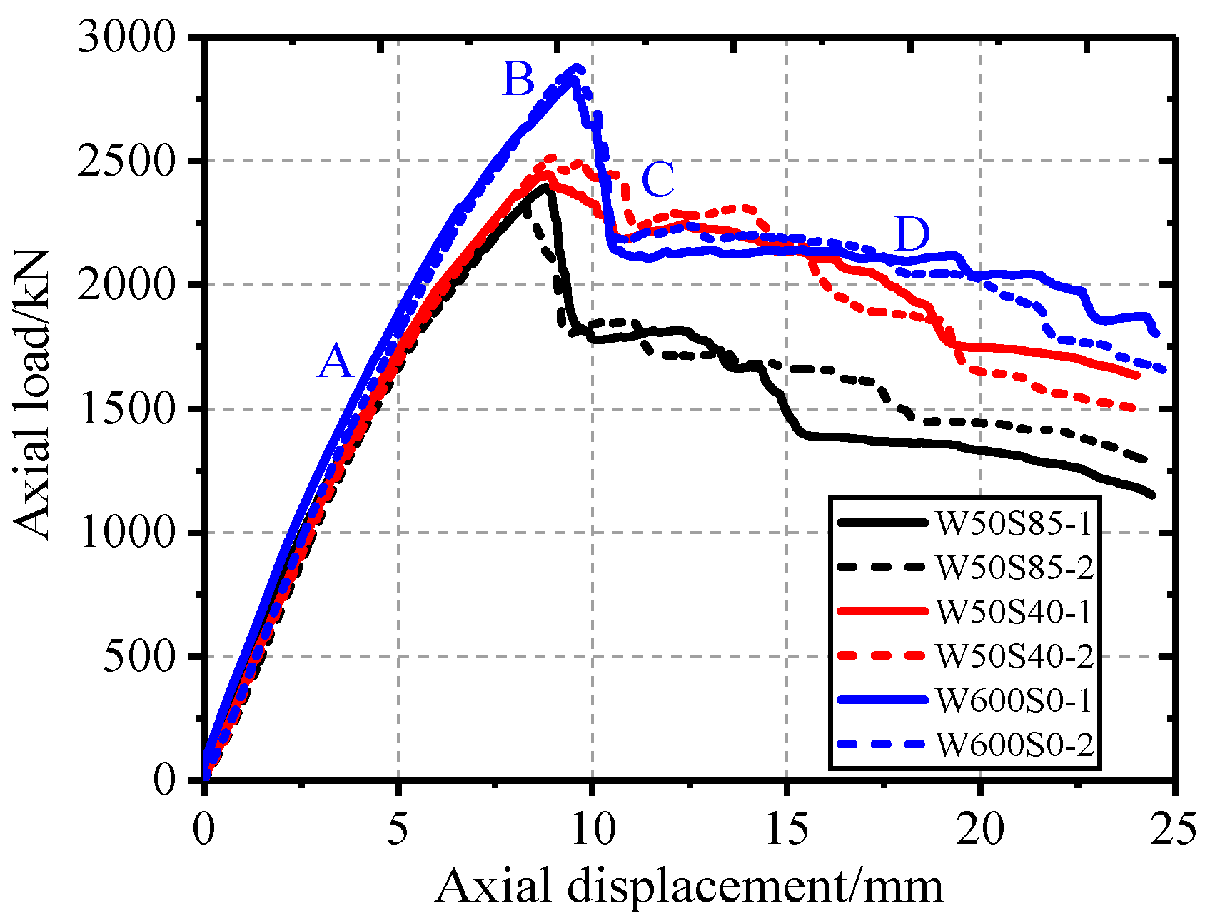
3.2. Axial Load–Displacement Curve
The axial load–displacement curve for each group of specimens is shown in Figure 5, where the displacement was the mean of the values measured by the two displacement gauges.
As shown in Figure 5, the load–displacement relationship curves of the same group of specimens basically overlap, and the errors of the peak load are all within 3%. The load–displacement curves of the three groups of specimens exhibit the same characteristics.
According to the characteristics of the load–displacement curve of the GFRP-confined concrete composite column, the load–displacement curve of the specimen can be roughly divided into four stages:
(1) In the elastic stage (OA), the internal concrete was in an elastic state, and the load was mainly carried by the concrete. At this stage, the load–displacement curves of three groups of specimens increase linearly, and various specimens showed a similar initial stiffness;
(2) In the strengthening stage (AB), the concrete expanded after it crushed. At this stage, the GFRP provided a lateral confining force, and the internal concrete was in triaxial compression state, which further improved the bearing capacity of the specimen;
(3) In the sudden decline stage (BC), as the axial displacement increased, the fiber in the GFRP tube was ruptured, and the load suddenly declined to approximately 75% of the peak value;
(4) In the ductile failure stage (CD), the specimen entered a relatively stable platform section due to the confinement of the externally wrapped GFRP strips, showing ductile failure following the rupture of the GFRP tube.
After entering AB, the stiffness and peak loads of the specimens in the W600S0 group were higher than those of the specimens in other groups, thereby indicating that continuously wrapped GFRP strips can effectively improve the compressive stiffness and load capacity of the composite column.
The main test results are shown in Table 4. Compared with the values of the specimen with a wrapping interval of 85 mm, the peak load with a wrapping interval of 40 mm increased by 5%, and the peak load capacity of the entirely wrapped GFRP increased by 21%, thereby indicating that reducing the GFRP wrapping interval can increase the ultimate bearing capacity and ductility of the specimen.
To quantify plastic deformation of specimens, ductility coefficient was used to evaluate different specimens:
where μ is ductility coefficient, eu is axial displacement corresponding to bearing capacity and ey is axial displacement corresponding to equivalent yield load. Equivalent yield load is determined by the farthest method suggested by Feng Peng et al. [21,22].
It can be seen from Table 5 that the ductility coefficients of W50S40 and W600S0 are 21.4% and 38.5% higher than those of W50S85, respectively. This shows that with the decrease in the net spacing of external GFRP strips, the ductility of the specimen is significantly improved.
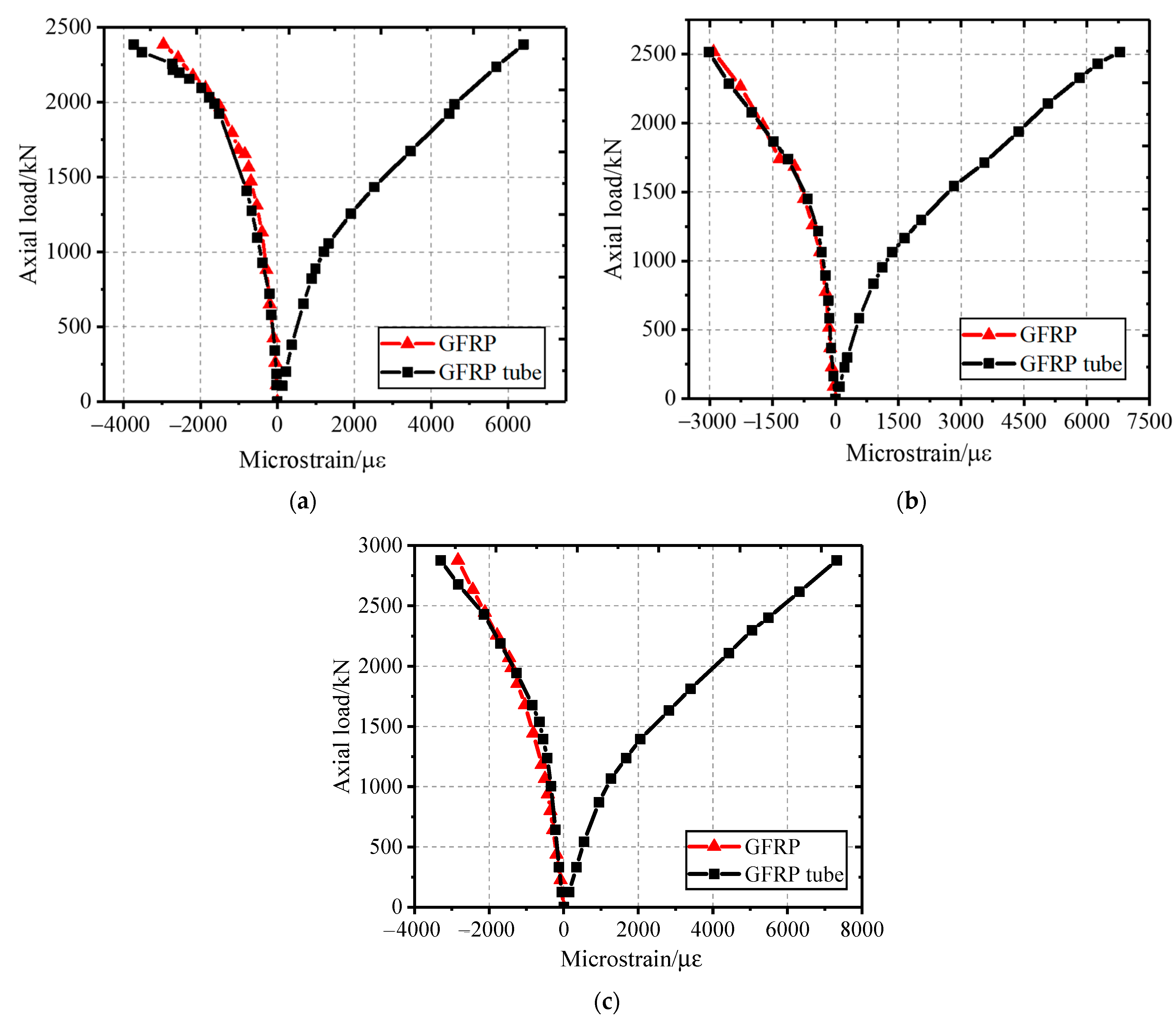
3.3. Axial Load–Strain Curve
The axial load–strain curve is plotted according to the average values of the strain data at each strain gauge in the section of the specimen column, as shown in Figure 6, where the positive value of the abscissa indicates the longitudinal strain, and the negative value represents the lateral strain. The axial load–strain curves of the three groups of specimens all exhibit typical nonlinear characteristics, which can be roughly divided into two stages, namely, the elastic stage and post-yield strengthening stage. At the initial stage of loading, the curve showed linear growth. The longitudinal strain growth rate of the GFRP tube was obviously greater than that of the lateral strain. The specimen underwent longitudinal deformation and slight lateral expansion. The GFRP tube exerted a weak confining effect on the internal concrete. With the increase in the load, the concrete inside the tube was crushed and lateral expansion occurs, the inner wall of the tube was subjected to the pressure of the internal concrete, and the growth rate of the lateral strain of the GFRP tube accelerated.
The lateral strain on the same section of the externally wrapped GFRP strips and GFRP tube increased with the load in a similar trend. W50S85-1, W50S40-2, and W600S0-2 are taken as examples, and the lateral deformations of the GFRP tube and externally wrapped GFRP strips were basically the same under the load action, thereby indicating that the impact of bond-slip between composite materials on the mechanical properties of the structure was negligible.
4. Finite Element Analysis Model
4.1. Material Model
The finite element software ABAQUS was used to establish a model for composite GFRP-confined concrete square columns for simulation analysis. As the model involves multiple components of concrete, GFRP tubes, and external GFRP, the convergence of the model is poor. Therefore, the first-order element with good convergence was used in the selection of various models. The eight-node hexahedron complete integral element (C3D8R) with reduced integral was used in concrete and GFRP tubes, and the best results can be obtained at the lowest cost for three-dimensional problems. External GFRP adopts four-node conventional shell element (S4R), which has stable performance and wide application range [23,24]. The plastic damage model of concrete is a continuous damage model based on plastic, which takes into account the tensile and compressive properties of materials and has good convergence. It can simulate the ultimate compressive stress and plastic deformation of concrete under low confining pressure. Therefore, the plastic damage model was adopted in this paper [25,26], and the CDP model parameters are shown in Table 6.
Relations of concrete in uniaxial stress state is determined by the following formulas:
Note: and are tensile stress and compressive stress, respectively; and are tensile strain and compressive strain, respectively; and are tensile plastic strain of concrete and compressive plastic strain, respectively. and are uniaxial tensile damage evolution coefficient of concrete and uniaxial compression damage evolution coefficient of concrete, respectively; is tensile cracking strain; is undamaged tensile elastic strain; is compressive inelasticity strain; and is undamaged compressive elastic strain.
We referred to the Code for Design of Concrete Structures (GB50010-2010) [27,28] for the compressive constitutive of concrete, and adopted the material property test data for the concrete compressive strength, GFRP tube elastic modulus, and GFRP elastic modulus. Both GFRP tubes and wrapped GFRP adopt ideal linear elastic model. Combined with the literature [29,30], we assigned properties to the above materials.
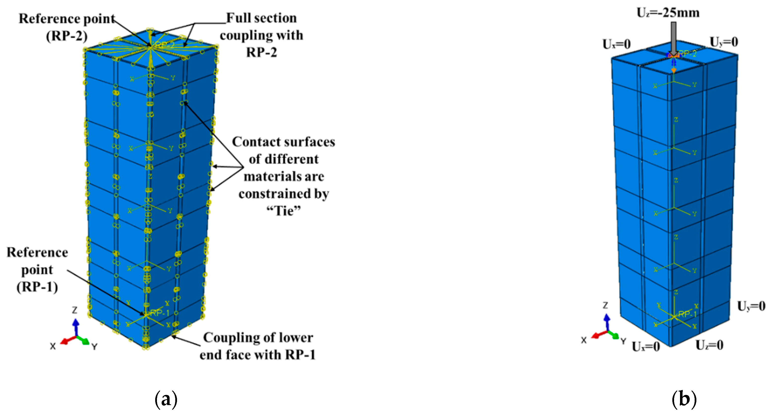
During the test, the contact surfaces of the specimen could undergo cooperative deformation, and no slip occurred before the fiber broke. In the finite element model, the contact surface adopted the “tie” confinement [31], as shown in Figure 7a. From the stress state of the specimen under the axial compression load, it is clear that the contact surface between the specimen and the end was not smooth. Under the action of a large axial load, substantial friction existed between the end face of the specimen and the end plate, thereby limiting the degree of freedom of the specimen in the X and Y directions.
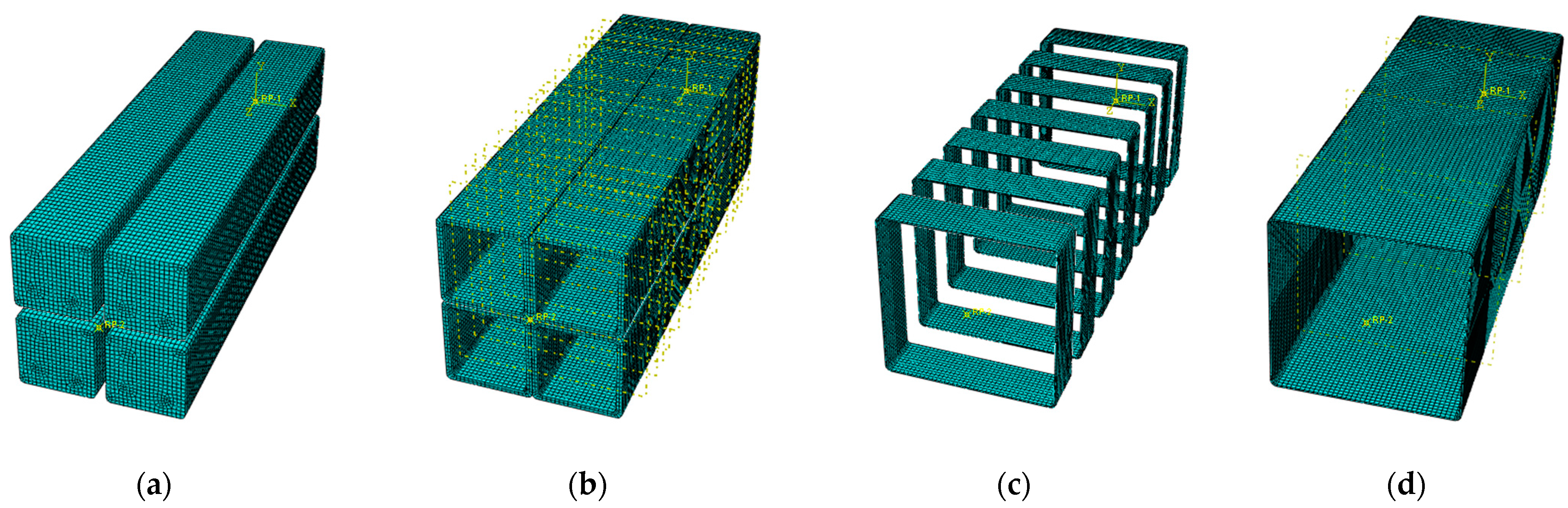
Combined with the finite element model setting method proposed by Teng et al. [32,33], the bottom of the numerical model column was assumed to be completely fixed, and the coupling point was set on the column top. Only the degree of freedom in the Z direction was retained, and a displacement of 25 mm was applied in the Z direction, as shown in Figure 7b. The mesh refinement method was used to external GFRP to ensure the rationality of mesh generation for the model, as shown in Figure 8.
4.2. Test Verification
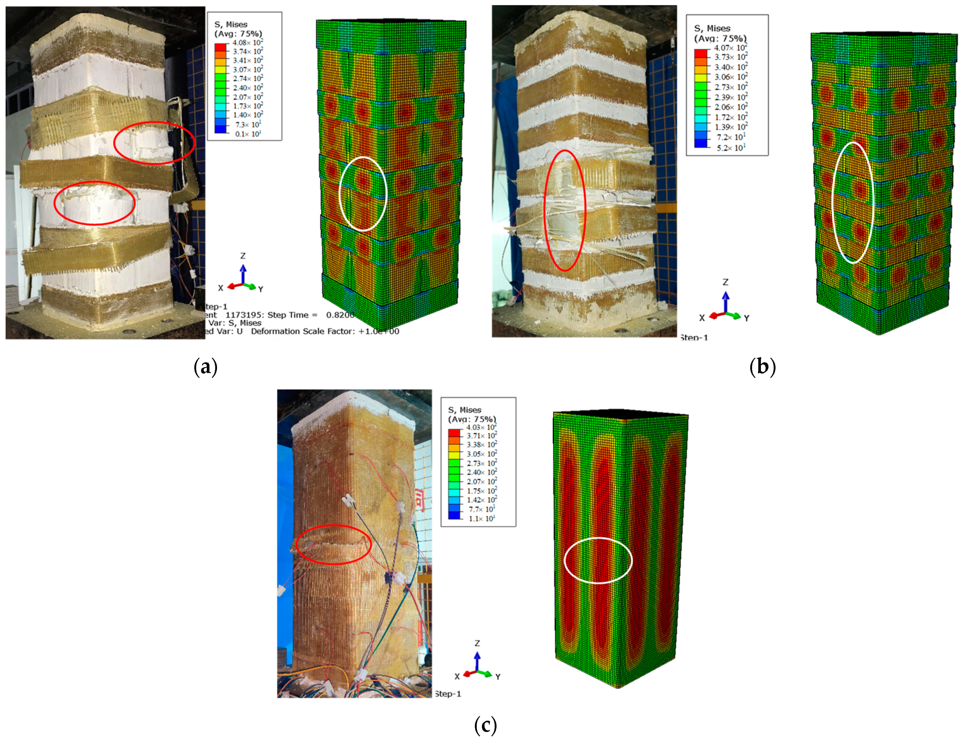
The abovementioned finite element model was used to simulate the experiment, and the failure mode obtained with the finite element method was compared with the experimental failure, as shown in Figure 9. The experimental results show that the fracture of GFRP tube can be regarded as the failure point of the specimen, and the linear elastic model is used for GFRP tube and GFRP. Therefore, it is considered that the numerical model reaches the load capacity when the stress of GFRP tube reaches the fracture strength of the mechanical properties test. Table 7 shows the load capacity of the composite column simulated by the finite element method and the ratio of the simulated load capacity to the experimental load capacity. The analysis results show that the errors between the load capacity values of the composite column calculated by the finite element model in this study and the experimental values were all within 5%, thereby indicating that the numerical simulation results were in good agreement with the experimental results.
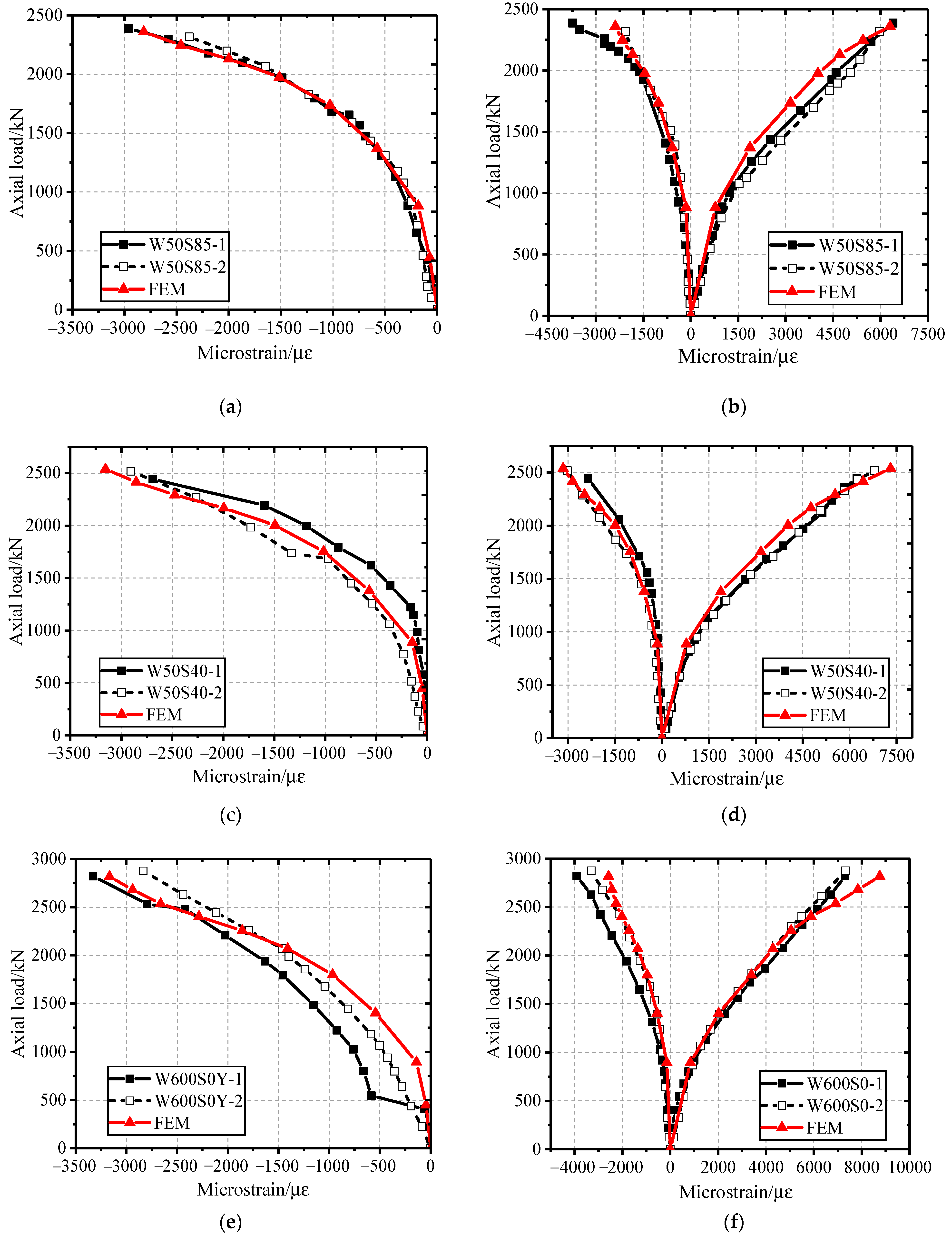
Figure 10 is a comparison of the load–strain relationship curve simulated by the finite element method with the experimental curve. The lateral strain of the externally wrapped GFRP strips and the lateral/longitudinal strain of the GFRP tube calculated by the infinite element method were basically consistent with the experimental results, which introduced a basis for the subsequent parametric analysis using the finite element method.
4.3. Parametric Analysis
Using the abovementioned finite element model, we conducted a numerical analysis on this type of composite GFRP-confined concrete square column, and studied the law for the impact of the GFRP layers and the GFRP strip interval on the bearing capacity of the composite column. The specimen design based on the finite element simulation method is shown in Table 8, and the section size and height of the specimen are consistent with that above.
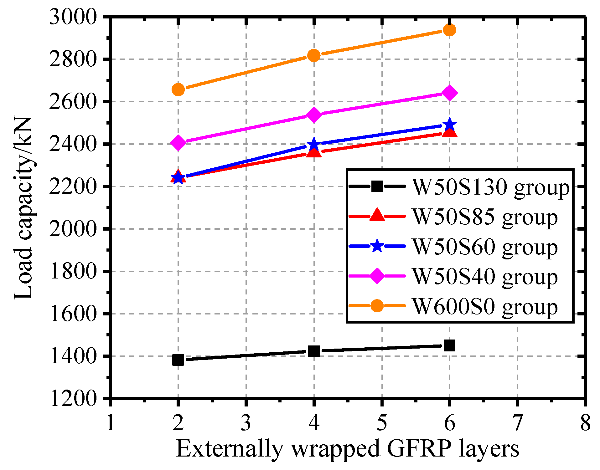
Figure 11 shows the impact of the externally wrapped GFRP fiber layers on the load capacity of the composite column. As shown in the figure, when the clear spacing of the GFRP strips is constant, the load capacity of the composite column shows an approximate linear growth with the increase in the externally wrapped GFRP layers.
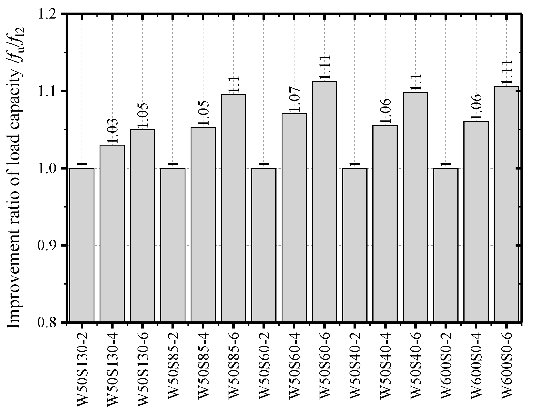
To quantify the role of externally wrapped GFRP layers in improving the load capacity of the composite column, the bearing capacity fl2 of the specimen wrapped with two layers of GFRP strips was used to normalize the load capacity fu of the corresponding specimen and obtain the improvement ratio fu/fl2 of the load capacity. As shown in Figure 12, with the increase in the wrapping layers, the improvement ratio of the load capacity exhibits an approximate linear growth, thereby indicating that the number of externally wrapped GFRP layers is an important factor in controlling the load capacity.
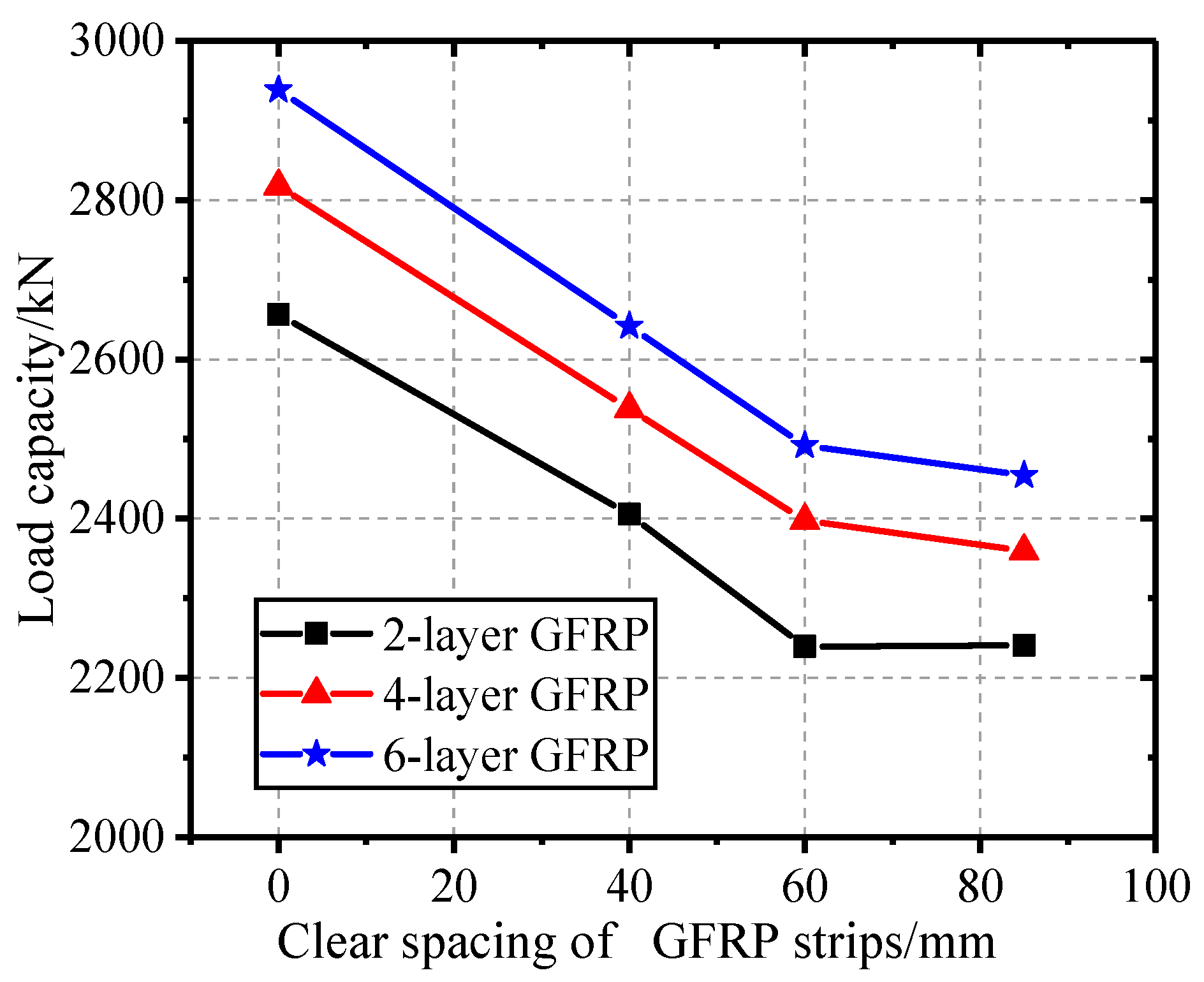
Figure 13 shows the influence of the net interval of externally wrapped GFRP strips on the load capacity of composite columns with the same numbers of layers of externally wrapped GFRP. Compared with the load capacity of the fully wrapped specimen, the bearing capacities of the specimens in the W50S40, W50S60, and W50S85 groups decreased by averages of 9.8%, 15.3%, and 16.1%, respectively, as shown in Table 9.
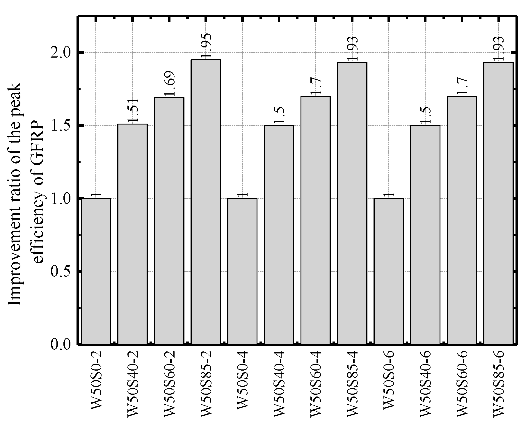
To analyze the impact of different wrapping methods on the confining effect of GFRP, the ratio of the load capacity of the specimen to the corresponding externally wrapped GFRP area is defined as the peak efficiency of the GFRP (unit: N/mm2). Figure 14 reflects that the peak efficiency of GFRP increases with the clear spacing of the external wrapping for a certain number of wrapped layers, thereby indicating that, compared to the entirely wrapped method, the use of GFRP strips for wrapping makes it both convenient for construction and conducive to the full utilization of the material properties of GFRP.
To quantitatively evaluate the peak efficiency of GFRP, the peak efficiency of the entirely wrapped GFRP specimen was used to normalize the peak efficiency of the specimen wrapped with the same layers of GFRP strips to obtain the improvement ratio of the peak efficiency of GFRP strips, as shown in Table 10. The results show that, compared with the entirely wrapped GFRP specimens, the peak efficiency of the GFRP strips in the W50S40, W50S60, and W50S85 groups improved by approximately 50%, 70%, and 93%, respectively.
5. Conclusions
A new type of composite column, which is referred to as a composite concrete column in which GFRP is externally wrapped over several GFRP square tubes to form a multicavity GFRP tube, and then concrete is poured inside, was introduced and tested under compressive loading. The failure modes, axial load–displacement relationships, and axial load–strain responses were determined. The failure modes and mechanical characteristics were investigated. To determine the overall mechanical behavior of the novel composite columns, finite element models were proposed. The corresponding major conclusions are summarized as follows:
- (1)
- The failure mode of the composite GFRP-confined concrete square column was internal concrete collapse. The GFRP tube reached the load capacity before it ruptured, the composite column expanded peripherally, the externally wrapped GFRP fiber broke successively, and the specimen exhibited ductile failure;
- (2)
- Based on a comparison of the load–strain relationship curves of the GFRP tube and externally wrapped GFRP strips, it is evident that the two are highly consistent, thereby indicating that the externally wrapped GFRP strips and pultruded GFRP tube could undergo cooperative deformation under the action of axial loading, and the impact of bond slip between the materials was negligible on the mechanical properties of the structure;
- (3)
- An increase in the number of externally wrapped GFRP fiber layers or a reduction in the clear spacing of GFRP strips could improve the load capacity of the composite columns. The GFRP numerical model adopts a linear elastic model, and the bearing capacity of the specimen can be predicted by the tensile strength of GFRP in the model, which is in good agreement with the experimental results. However, in order to obtain more accurate results in subsequent studies, the failure criterion of FRP should be introduced to improve the model;
- (4)
- Compared with the performance of the entirely wrapped GFRP tube, the load capacity of the specimens in the W50S40 group declined by 9.8%, while the peak efficiency of the GFRP strips increased by 50%. The adoption of proper GFRP layers and strip intervals not only facilitates convenient construction, but also ensures that the bearing capacity of the composite column is appropriate and that the material properties of GFRP are fully utilized.
Author Contributions
Conceptualization, Y.Q.; methodology, J.L., Y.Q. and X.W.; software, J.L. and X.W.; validation, Y.Q. and J.L.; formal analysis, J.L.; investigation, J.L.; resources, J.L. and X.W.; data curation, J.L. and Y.L.; writing—original draft preparation, J.L. and Y.L.; writing—review and editing, J.L. and Y.Q.; visualization, J.L.; supervision, Y.Q. and J.L.; project administration, Y.Q.; funding acquisition, Y.Q. All authors have read and agreed to the published version of the manuscript.
Funding
This research was funded by the National Natural Science Foundation of China (grant number 51778286).
Institutional Review Board Statement
Not available.
Informed Consent Statement
Not available.
Data Availability Statement
Not available.
Acknowledgments
The experiment was conducted in the Nanjing Tech Civil Engineering Laboratory. I would like to thank my professor and our research team workers for their help. Furthermore, I would like to acknowledge the excellent three-dimensional concrete structures and corresponding finite element simulations provided by my predecessors.
Conflicts of Interest
The authors declare no conflict of interest.
References
- Halliwell, S. In-service performance of glass reinforced plastic composites in buildings. Struct. Build. 2004, 157, 99–104. [Google Scholar] [CrossRef]
- Yuan, F.; Chen, L.P.; Chen, M.C.; Xu, K.C. Behaviour of Hybrid Steel and FRP-Reinforced Concrete—ECC Composite Columns under Reversed Cyclic Loading. Sensors 2018, 18, 4231. [Google Scholar] [CrossRef] [Green Version]
- Saadatmanesh, H.; Ehsani, M.R.; Li, M.W. Strength and Ductility of Concrete Columns Externally Reinforced with Fiber Composite Straps. Struct. J. 1994, 91, 434–447. [Google Scholar]
- Karam, G.; Tabbara, M. Confinement Effectiveness in Rectangular Concrete Columns with Fiber Reinforced Polymer Wraps. J. Compos. Constr. 2005, 9, 388–396. [Google Scholar] [CrossRef]
- Lu, C.; Ni, M.; Chu, T.; He, L. Comparative investigation on tensile performance of FRP bars after exposure to water, seawater and alkaline solutions. J. Mater. Civil. Eng. 2020, 32, 04020170. [Google Scholar] [CrossRef]
- Lau, D.; Qiu, Q.W.; Zhou, A.; Chow, C.L. Long term performance and fire safety aspect of FRP composites used in building structures. Constr. Build. Mater. 2016, 126, 573–585. [Google Scholar] [CrossRef]
- Kang, I.K.; Kim, S.H. Compressive Strength Testing of Hybrid Concrete-Filled Fiber-Reinforced Plastic Tubes Confined by Filament Winding. Appl. Sci. 2021, 11, 2900. [Google Scholar] [CrossRef]
- Allam, K.; Mosallam, A.S.; Salama, M.A. Experimental evaluation of seismic performance of interior RC beam-column joints strengthened with FRP composites. Eng. Struct. 2019, 196, 109308.1–109308.22. [Google Scholar] [CrossRef] [Green Version]
- Wang, X.; Qi, Y.; Sun, Y.; Xie, Z.; Liu, W. Compressive behavior of composite concrete columns with encased FRP confined concrete cores. Sensors 2019, 19, 1792. [Google Scholar] [CrossRef] [PubMed] [Green Version]
- Cascardi, A.; Lerna, M.; Micelli, F.; Aiello, M.A. Discontinuous FRP-confinement of masonry columns. Front. Built Environ. 2020, 5, 147. [Google Scholar] [CrossRef]
- Guades, E.; Aravinthan, T.; Islam, M. Characterisation of the mechanical properties of pultruded fiber-reinforced polymer tube. Mater. Des. 2014, 63, 305–315. [Google Scholar] [CrossRef]
- Martin, J. Pultruded composites compete with traditional construction materials. Reinf. Plast. 2006, 50, 20–27. [Google Scholar] [CrossRef]
- Bannister, M. Challenges for composites into the next millennium-a reinforcement perspective. Compos. Part. A 2001, 32, 901–910. [Google Scholar] [CrossRef]
- Yang, J.; Wang, J.; Wanhg, Z. Axial compressive behavior of FRP nonuniformly wrapped seawater sea-sand concrete in square columns. Acta Mater. Compos. Sin. In Press (In Chinese).
- Chen, L.; Aimin, Y.; Danying, G.; Pu, Z. Axial compression test of corroded reinforced concrete columns strengthened with FRP strips under corrosive environment. Acta Mater. Compos. Sin. 2020, 37, 2015–2028. (In Chinese) [Google Scholar]
- Jie, C.; Yujun, Q.; Zhijin, X. Experiment on axial compression performance of GFRP-walled concrete-filled steel tube columns. Acta Mater. Compos. Sin. 2021, 38, 1825–1837. (In Chinese) [Google Scholar]
- ASTM D3039/3039M-14. Standard Test Method for Tensile Properties of Polymer Matrix Composite Materials; ASTM International: West Conshohocken, PA, USA, 2014. [Google Scholar]
- ASTM D3410/D3410M-16. Standard Test Method for Compressive Properties of Polymer Matrix Composite Materials with Unsupported Gage Section by Shear Loading; ASTM International: West Conshohocken, PA, USA, 2016. [Google Scholar]
- Test Method for Axial Compression Performance of Fiber-reinforced Thermosetting Plastic Pipe; National Standard of the People’s Republic of China GB/T 5350-2005; China Standard Press: Beijing, China, 2005.
- Standard for Test Methods of Mechanical Properties of Ordinary Concrete; National Standard of the People’s Republic of China GB/T 50081-2002; China Building Industry Press: Beijing, China, 2003.
- Peng, F.; Hanlin, Q.; Lieping, Y. The definition and discussion of ‘yield point’ of materials, components and structures. Eng. Mech. 2017, 34, 36–46. (In Chinese) [Google Scholar]
- Cheng, S.; Feng, P.; Bai, Y.; Ye, L.P. Load-Strain Model for Steel-Concrete-FRP-Concrete Columns in Axial Compression. J. Compos. Constr. 2016, 20, 04016017. [Google Scholar] [CrossRef]
- Yu, T.; Teng, J.G.; Wong, Y.L.; Dong, S.L. Finite element modeling of confined concrete-II: Plastic-damage model. Steel Constr. 2010, 32, 680–691. [Google Scholar] [CrossRef]
- Junlin, Z.; Huitao, R.; Suyan, W. Finite element analysis of the constraint performance of FRP pipe-concrete-steel pipe composite casing. J. Dalian Univ. Technol. 2016, 56, 375–381. (In Chinese) [Google Scholar]
- Lubliner, J.; Oliver, J.; Oller, S.; Oñate, E. A plastic-damage model for concrete. Int. J. Solids Struct. 1989, 25, 299–326. [Google Scholar] [CrossRef]
- Lee, J.; Fenves, G.L. Plastic-Damage Model for Cyclic Loading of Concrete Structures. J. Eng. Mech. 1998, 124, 892–900. [Google Scholar] [CrossRef]
- GB 50010-2010. National Standard of the People’s Republic of China. Code for Design of Concrete Structures; China Architecture and Building Press: Beijing, China, 2010. (In Chinese) [Google Scholar]
- Lam, L.; Teng, J.G. Design-oriented Stress–Strain Model for FRP-confined Concrete in Rectangular Columns. J. Reinf. Plast. Compos. 2003, 22, 1149–1186. [Google Scholar] [CrossRef]
- Feroldi, F.; Russo, S. Structural Behavior of All-FRP Beam-Column Plate-Bolted Joints. J. Compos. Constr. 2016, 20, 04016004. [Google Scholar] [CrossRef] [Green Version]
- Czapski, P.; Kubiak, T. Numerical and experimental investigations of the post-buckling behaviour of square cross-section composite tubes. Compos. Struct. 2015, 132, 1160–1167. [Google Scholar] [CrossRef]
- Guo, K.; Guo, Q.; Wang, Y. Effect of Bond-Slip on Dynamic Response of FRP-Confined RC Columns with Non-Linear Damping. Appl. Sci. 2021, 11, 2124. [Google Scholar] [CrossRef]
- Teng, J.G.; Hu, Y.M. Behaviour of FRP-jacketed circular steel tubes and cylindrical shells under axial compression. Constr. Build. Mater. 2007, 21, 827–838. [Google Scholar] [CrossRef]
- Vincent, T.; Ozbakkaloglu, T. Influence of fiber orientation and specimen end condition on axial compressive behavior of FRP-confined concrete. Constr. Build. Mater. 2013, 47, 814–826. [Google Scholar] [CrossRef]
Figure 1.
GFRP confined column.

Figure 2.
Test loading device.

Figure 3.
Location of the strain gauges: (a) W600S0-GFRP tube; (b) W600S0-GFRP; (c) W50S85-GFRP tube; and (d) W50S85-GFRP.
Figure 3.
Location of the strain gauges: (a) W600S0-GFRP tube; (b) W600S0-GFRP; (c) W50S85-GFRP tube; and (d) W50S85-GFRP.

Figure 4.
Test phenomenon of specimen W50S85. (a) Repture of the GFRP tube; (b) Successive rupture of the GFRP tube; (c) Shear damage of the GFRP tube; (d) Cornr rupture of the GFRP tube.
Figure 4.
Test phenomenon of specimen W50S85. (a) Repture of the GFRP tube; (b) Successive rupture of the GFRP tube; (c) Shear damage of the GFRP tube; (d) Cornr rupture of the GFRP tube.

Figure 5.
Axial load–displacement curve.

Figure 6.
Axial load–strain relationship curve: (a) W50S85-1; (b) W50S40-2; (c) W600S0-2.

Figure 7.
Numerical model: (a) Interaction of Numerical Models; (b) Boundary conditions of numerical model.
Figure 7.
Numerical model: (a) Interaction of Numerical Models; (b) Boundary conditions of numerical model.

Figure 8.
Meshing of finite element model: (a) Internal Concrete; (b) GFRP tubes; (c) GFRP strips interval wrapped; (d) GFRP entirely wrapped.
Figure 8.
Meshing of finite element model: (a) Internal Concrete; (b) GFRP tubes; (c) GFRP strips interval wrapped; (d) GFRP entirely wrapped.

Figure 9.
Comparison of the experimental failure results with the finite element simulation results: (a) W50S85; (b) W50S40; and (c) W600S0.
Figure 9.
Comparison of the experimental failure results with the finite element simulation results: (a) W50S85; (b) W50S40; and (c) W600S0.

Figure 10.
Comparison of the finite element calculation results with the experimental load–strain relationship curve: (a) W50S85-GFRP lateral strain; (b) W50S85-GFRP tube lateral/longitudinal strain; (c) W50S40-GFRP lateral strain; (d) W50S40-GFRP tube lateral/longitudinal strai€ (e) W600S0-GFRP lateral strain; and (f) W600S0-GFRP tube lateral/longitudinal strain.

Figure 11.
Impact of the GFRP fiber layers on the load capacity.

Figure 12.
Improvement ratio of the externally wrapped GFRP layers to the peak carrying capacity.

Figure 13.
Impact of the clear spacing of the externally wrapped GFRP strips on the load capacity.

Figure 14.
Peak efficiency of GFRP.


Table 1.
Parameters of the composite column specimens.
| Specimen Number | Section Size L × B/mm | Specimen Height H/mm | Chamfer Radius R/mm | GFRP Width W/mm | GFRP Clear Spacing S/mm | Number of GFRP Layers |
|---|---|---|---|---|---|---|
| W600S0-1, 2 | 204 × 204 | 600 | 5 | 600 | / | 4 |
| W50S40-1, 2 | 204 × 204 | 600 | 5 | 50 | 40 | 4 |
| W50S85-1, 2 | 204 × 204 | 600 | 5 | 50 | 85 | 4 |
Note: W—GFRP width; S—Clear spacing of the GFRP; and 1, 2—Specimen numbers.
Table 2.
Mechanical properties of composite materials.
| Material Properties | GFRP Tube | GFRP |
|---|---|---|
| ffrp/MPa | 330.0 | 400.0 |
| f’frp/Mpa | 115.0 | - |
| εfrp | 0.014 | 0.015 |
| ε’frp | 0.007 | - |
| E1/Gpa | 24.4 | 26.2 |
| E2/Gpa | 17.5 | - |
| υ12 | 0.35 | 0.32 |
Note: ffrp—tensile strength, f’frp—compressive strength, εfrp—ultimate tensile strain, ε’frp—ultimate compressive strain, E1—tensile modulus, E2—compressive modulus, and υ12—Poisson’s ratio.
Table 3.
Compressive properties of concrete.
| Fcu/Mpa | εcu | Ec/Gpa | υ | fr/Mpa | ft/Mpa |
|---|---|---|---|---|---|
| 30.8 | 0.004 | 30.0 | 0.2 | 4.62 | 2.77 |
Note: fcu—compressive strength of the cube, εcu—ultimate strain, Ec—modulus of elasticity, and υ—Poisson’s ratio, fr—residual compressive strength, and ft—tensile strength.
Table 4.
Load capacity of the specimens.
| Specimen Number | Nmax /kN | UNmax /mm | Nmax,ave /kN | I/% |
|---|---|---|---|---|
| W50S85-1 | 2392 | 8.81 | 2358.5 | - |
| W50S85-2 | 2325 | 8.25 | ||
| W50S40-1 | 2446 | 8.66 | 2482.0 | 5% |
| W50S40-2 | 2518 | 8.96 | ||
| W600S0-1 | 2830 | 9.50 | 2857.0 | 21% |
| W600S0-2 | 2884 | 9.61 |
Note: Nmax—ultimate load, UNmax—axial displacement corresponding to the ultimate load of the specimen, Nmax,ave—mean of the ultimate load of the same specimens, and I—increase in the load capacity.
Table 5.
Ductility of the specimens.
| Specimen Number | ey /mm | eu /mm | μ | μa | I |
|---|---|---|---|---|---|
| W50S85-1 | 3.8 | 8.83 | 2.32 | 2.20 | - |
| W50S85-2 | 3.93 | 8.18 | 2.08 | ||
| W50S40-1 | 3.33 | 8.82 | 2.65 | 2.67 | 21.4% |
| W50S40-2 | 3.32 | 8.96 | 2.7 | ||
| W600S0-1 | 2.94 | 9.5 | 3.24 | 3.05 | 38.5% |
| W600S0-2 | 3.32 | 9.53 | 2.87 |
Note, μa—average ductility coefficient, I—improvement ratio of the ductility.
Table 6.
Parameters of the concrete plastic damage model.
| Ψ (°) | ϵ | σb0/σc0 | Kc | μ |
|---|---|---|---|---|
| 30 | 0.1 | 1.16 | 0.6667 | 0.0005 |
Note: Ψ—dilatancy angle, ϵ—flow potential eccentricity, σb0/σc0—the ratio of initial equibiaxial compressive yield stress to initial uniaxial compressive yield stress, Kc—the ratio of the second stress invariant on the tensile meridian, and μ—viscosity parameter.
Table 7.
Comparison of the finite element simulation results and the experimental load capacity values.
Table 7.
Comparison of the finite element simulation results and the experimental load capacity values.
| Specimen Number | NF,Max/kN | NT,Max/kN | NF,Max/NT,Max |
|---|---|---|---|
| W50S85-1 | 2359 | 2392 | 0.986 |
| W50S85-2 | 2325 | 1.015 | |
| W50S40-1 | 2538 | 2446 | 1.038 |
| W50S40-2 | 2518 | 1.008 | |
| W600S0-1 | 2818 | 2830 | 0.996 |
| W600S0-2 | 2884 | 0.977 |
Note: NF,Max represents the finite element simulation values, and NT,Max represents the experimental value.
Table 8.
Design parameters of the finite element model.
| Specimen Number | W/mm | S/mm | L |
|---|---|---|---|
| W50S130L2 | 50 | 130 | 2 |
| W50S130L4 | 50 | 130 | 4 |
| W50S130L6 | 50 | 130 | 6 |
| W50S85L2 | 50 | 85 | 2 |
| W50S85L4 | 50 | 85 | 4 |
| W50S85L6 | 50 | 85 | 6 |
| W50S60L2 | 50 | 60 | 2 |
| W50S60L4 | 50 | 60 | 4 |
| W50S60L6 | 50 | 60 | 6 |
| W50S40L2 | 50 | 40 | 2 |
| W50S40L4 | 50 | 40 | 4 |
| W50S40L6 | 50 | 40 | 6 |
| W600S0L2 | 600 | 0 | 2 |
| W600S0L4 | 600 | 0 | 4 |
| W600S0L6 | 600 | 0 | 6 |
Note: W—width of the strip—type GFRP fiber cloth, S—clear spacing of the strip interval—wrapped GFRP fiber cloth, and L—layers of GFRP fiber cloth.
Table 9.
Impact of the wrapping interval of the GFRP strip on the load capacity.
| Specimen Number | Load Capacity/kN | η/% |
|---|---|---|
| W50S0-2 | 2656.67 | - |
| W50S40-2 | 2405.42 | −9.5% |
| W50S60-2 | 2239.39 | −15.7% |
| W50S85-2 | 2240.89 | −15.7% |
| W50S0-4 | 2817.63 | - |
| W50S40-4 | 2538.05 | −9.9% |
| W50S60-4 | 2397.70 | −14.9% |
| W50S85-4 | 2359.37 | −16.3% |
| W50S0-6 | 2938.61 | - |
| W50S40-6 | 2641.68 | −10.1% |
| W50S60-6 | 2491.66 | −15.2% |
| W50S85-6 | 2454.43 | −16.5% |
Note: η—Improvement ratio of the load capacity.
Table 10.
Improvement ratio of the peak efficiency of GFRP strips.
| Specimen Number | GFRP Peak Efficiency N/mm2 | Improvement Ratio of the Peak Efficiency of GFRP |
|---|---|---|
| W50S0-2 | 2.71 | - |
| W50S40-2 | 4.09 | 51% |
| W50S60-2 | 4.57 | 69% |
| W50S85-2 | 5.28 | 95% |
| W50S0-4 | 1.44 | - |
| W50S40-4 | 2.16 | 50% |
| W50S60-4 | 2.45 | 70% |
| W50S85-4 | 2.78 | 93% |
| W50S0-6 | 1.00 | - |
| W50S40-6 | 1.50 | 50% |
| W50S60-6 | 1.70 | 70% |
| W50S85-6 | 1.93 | 93% |
Publisher’s Note: MDPI stays neutral with regard to jurisdictional claims in published maps and institutional affiliations. |
© 2021 by the authors. Licensee MDPI, Basel, Switzerland. This article is an open access article distributed under the terms and conditions of the Creative Commons Attribution (CC BY) license (https://creativecommons.org/licenses/by/4.0/).
Share and Cite
MDPI and ACS Style
Lu, J.; Qi, Y.; Li, Y.; Wang, X. Axial Compressive Performance of a Composite Concrete-Filled GFRP Tube Square Column. Appl. Sci. 2021, 11, 6757. https://doi.org/10.3390/app11156757
AMA Style
Lu J, Qi Y, Li Y, Wang X. Axial Compressive Performance of a Composite Concrete-Filled GFRP Tube Square Column. Applied Sciences. 2021; 11(15):6757. https://doi.org/10.3390/app11156757
Chicago/Turabian StyleLu, Jiancheng, Yujun Qi, Yifei Li, and Xuxu Wang. 2021. "Axial Compressive Performance of a Composite Concrete-Filled GFRP Tube Square Column" Applied Sciences 11, no. 15: 6757. https://doi.org/10.3390/app11156757
Note that from the first issue of 2016, this journal uses article numbers instead of page numbers. See further details here.