
Influence of Blade Thickness on Solid–Liquid Two-Phase Flow and Impeller Wear in a Ceramic Centrifugal Slurry Pump


School of Mechatronics and Information Engineering, Wuxi Vocational Institute of Arts and Technology, Wuxi 214206, China
*
Author to whom correspondence should be addressed.
Processes 2021, 9(8), 1259; https://doi.org/10.3390/pr9081259
Submission received: 30 June 2021
/
Revised: 14 July 2021
/
Accepted: 15 July 2021
/
Published: 21 July 2021
(This article belongs to the Section Energy Systems)
Abstract
:The impeller blades of ceramic slurry pumps are usually very thick for the purpose of prolonging the service life. In this paper, numerical simulations and wear test were conducted to investigate the influence of blade thickness on the solid–liquid two-phase flow and impeller wear in a ceramic centrifugal slurry pump. The wear test was conducted for CFD validation. The numerical results show that the incident angles of solid particles increase with increasing blade thickness, which results in larger wrap angles of the solid particle trajectories. The increasing wrap angles of the solid particle trajectories offset the region that the collisions between the blade pressure side and the solid particles side take place towards the impeller exit and lead to more impacts between the solid particles and the blade suction side. The numerical results are in good accordance with the wear pattern of the tested impellers, which demonstrates that the numerical method adopted in this paper is predictable in the abrasion of the impeller of a ceramic centrifugal slurry pump. The experimental results show that an increase in the blade thickness alleviates the abrasion of the leading edges and the pressure side of the impeller blades; however, it also aggravates the abrasion of the blade suction side and decreases the pump performance.
1. Introduction
In industries like metallurgy, mining, chemical engineering, and environmental protection, slurry pumps easily fail due to severe wear of the components, especially the impeller, caused by the frequent impingement of the solid particles in slurry. To address this problem, ceramic centrifugal slurry pumps can be utilized as a substitute for alloy pumps and nonmetal pumps. They have excellent resistance to abrasion, erosion, and high temperature, which can save massively on metal resources and prolong the service life of flow components, thus increasing enterprise efficiency [1]. The blade leading edges and the pressure side near the impeller periphery always undergo severe local abrasion, which leads to failure of the impeller [2]. Therefore, the ceramic centrifugal pumps usually utilize thicker impeller blades to prolong their service life. However, the thicker blade trailing edges results in an increase in the crowding coefficient, which can influence the flow pattern in the impeller passages, thus decreasing the pump suction performance [3,4].
Recently, a great amount of research regarding the influence of blade thickness variation on the flow in rotating machinery has been conducted [5,6,7,8,9]. However, only a few studies in the literature that examined the effect of blade thickness variation on the flow in centrifugal pumps could be found. For example, Jin et al. [10] found that an increase in the blade thickness would influence the outlet throat conditions, thus affecting the external characteristics of the centrifugal pump. Thicker blades were recommended to be adopted for a low-specific-speed centrifugal pump working under low flow rate conditions for a long time to improve the stability and performance of the pump. Tao et al. [11] studied the effect of the blade thickness on the pressure pulsations in a ceramic centrifugal slurry pump with annular volute, and they found that the pressure pulsations increased at the leading edges, however decreased at the trailing edges as the blade thickness increases. Qian et al. [12] studied the effect of the distribution of blade thickness on the vibration of a centrifugal pump. By changing the respective impeller angles on the pressure side and suction side along the blade-aligned streamwise location, the flow field could thereby be reordered. Deng et al. [13] studied the effect of collaborative design of the blade thickness and blade number on the performance of a centrifugal pump. Their research indicates that properly increasing the blade number and reducing the blade thickness in a synergistic scheme can improve the efficiency of the centrifugal pump and the uniformity of the liquid velocity distribution at the impeller cross section. The studies mentioned above are significant in revealing the effect of the blade thickness variation on the single-phase flow in centrifugal pumps. However, there are few studies aimed at the influence of blade thickness variation on solid–liquid two-phase flow in centrifugal pumps.
Within the last decade, solid–liquid two-phase flow in centrifugal pumps and its influence on the wear of hydraulic components has been investigated numerically and experimentally. Among the numerical methods that deal with the solid phase, there are mainly three solid–liquid two-phase flow models: the Eulerian–Eulerian model, Eulerian–Lagrange model, and Discrete Element Method (DEM). In the Euler–Euler model, the solid phase is treated as a pseudo-liquid medium. The solid particles’ motion was obtained through the solutions of the governing equations. This model has been widely used in engineering applications as a result of its applicability to a wide range of solid volume fractions and its relatively low demand for computational resources [14,15,16,17]. In the Euler–Lagrange model, the solid particles are particularly tracked in the Lagrangian frame of reference, rather than being treated as an extra Eulerian phase. Complete information on the behavior and residence time of individual particles and better details regarding mass and heat transfer are available, but the method is expensive in terms of computational resource demand [18,19,20]. The Discrete Element Method (DEM) uses DEM and CFD methods to iteratively solve for the particle motion and the fluid flow field in order to achieve momentum balance between the liquid and solid phases. This model can yield the more accurate analysis of solid particle motion in two-phase flow by considering the solid particle features and the collisions between particles; however, it demands a large amount of computational resources, which limits its applications in engineering [21,22,23]. Moreover, several experimental techniques have been utilized to conduct research on the erosion of pump components, including the paint wear method, measuring the weight loss of components, the PIV method, and so on [24,25,26].
The novelty of this paper is the study of the influence of blade thickness variation on the solid–liquid two-phase flow and the impeller wear in a centrifugal slurry pump, which is seldom reported. Ceramic centrifugal slurry pumps are usually transporting fluid that contains a large volume fraction of fine particles. Hence, after weighing the pros and cons of the three solid–liquid two-phase models, the Eulerian–Eulerian model was utilized to investigate the solid–liquid two-phase flow. Three impellers with varying blade thickness were designed for the investigation of the influence of blade thickness on the solid–liquid two-phase flow in a ceramic centrifugal slurry pump. A wear test rig was set up, and the wear patterns of two impellers were examined via the paint wear method so as to validate the accuracy of the numerical results. The results in this paper are expected to be beneficial to further design of impellers for ceramic slurry pumps in engineering applications.
2. Pump Geometry
The investigated pump is a horizontal single-stage centrifugal slurry pump. This pump is expected to operate at the flow rate of 100 m3/h with the rotational speed of 2900 r/min. The pump head is expected to be higher than 40 m. The annular volute casing is utilized for the purpose of alleviating the wear of the volute tongue. Because there is a fixed radial gap between the impeller exit and the wall of the volute casing. The cross-sectional area of the annular volute chamber was designed to be equal to that of the 8th cross-section of conventional spiral volute casing. The main geometric dimensions of the model pump are listed in Table 1.
To investigate the effect of blade thickness on the solid–liquid two-phase flow in the model pump, three impellers with different blade thickness were designed. As shown in Figure 1, the examined circumferential thicknesses of the blade at the impeller exit were 15 mm, 21.5 mm, and 28 mm. All three impellers have identical blade profiles of the pressure side, namely, inlet blade angle β1 = 20°, outlet blade angle β2 = 26°, and blade wrap angle φ = 120°.
3. Numerical Model and Methods
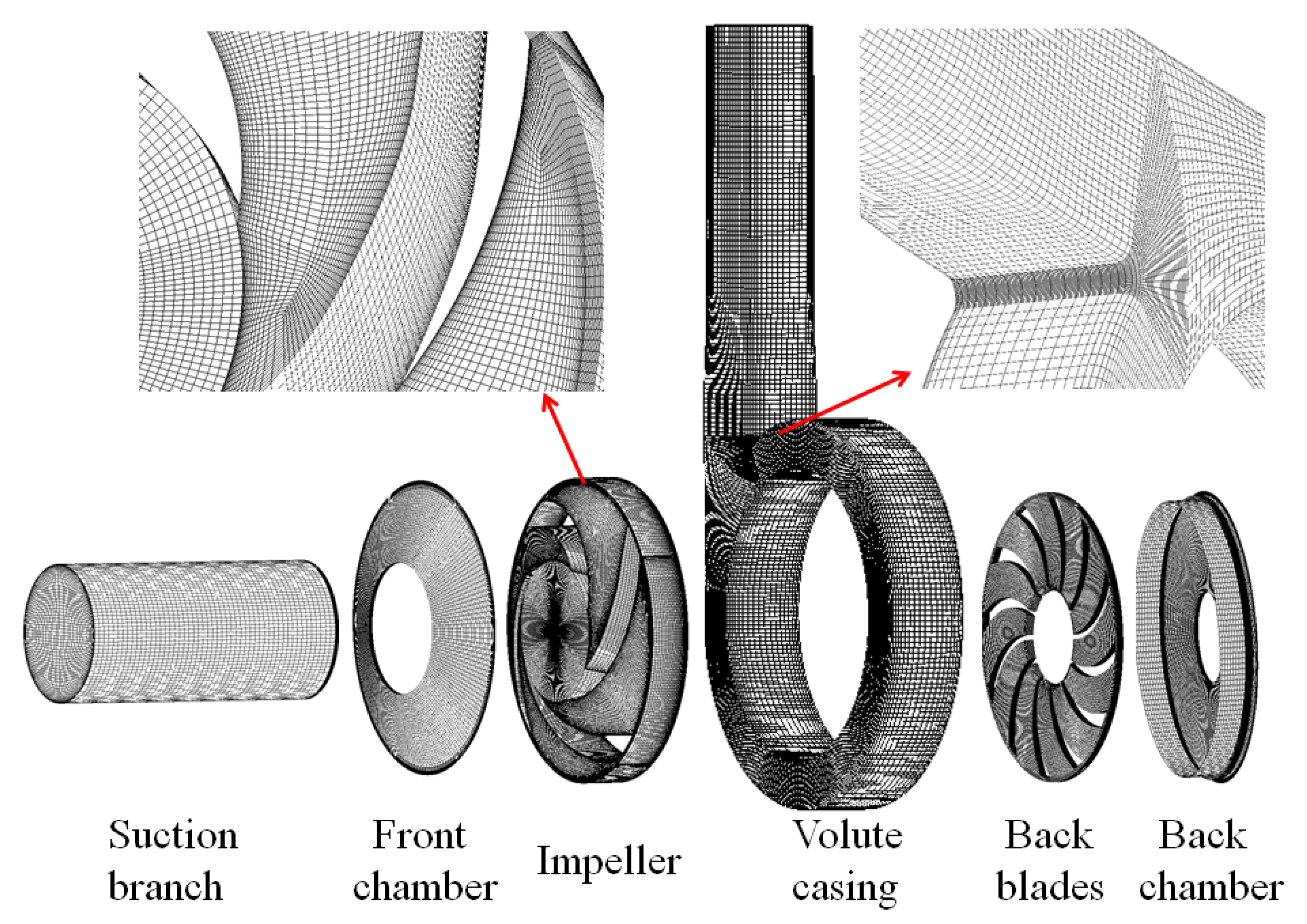
3.1. Computational Domain and Grid Meshing
The computational domain was separated into 6 subdomains, namely, the impeller, suction branch, front chamber, back chamber, back blades, and volute casing. The two chambers had a thickness of 3 mm. All 6 subdomains were meshed with hexahedral structured grids using ANSYS ICEM software. The grids close to the impeller surfaces and the volute tongue were refined with a wall y+ value between 30 and 120 for the treatment of the wall function. The grid meshing is illustrated in Figure 2. A GCI test, proposed by Roache, was conducted on the grids at the rated condition for Case 1 to measure the influence of grid refinement on the hydraulic performance of the model pump. The GCI is a percentage measure that indicates an error between the solution and the asymptotic value. The GCI is defined as
where Fs is a factor of safety, which is recommended to be Fs = 1.25 for comparisons over three or more grids. And, p is the resolution of convergence, which is recommended to be p = 1.97. The pump head H was selected as the observed value for ε. It can be seen in Table 2 that once the grid number reached 4.02 million, the change in GCI was less than 3%. Hence, a final mesh with a grid number of 4,021,768 was used in Case 1. There is no structural difference in all three impellers, hence the grid number and the refinement method were used for Case2 and Case 3.
3.2. Mathematical Model
To simulate the solid–liquid two-phase flow, the Particle model, which is the inhomogeneous model for Eulerian–Eulerian multiphase flow, was utilized. The Particle model assumes one of the phases is continuous (phase α) and the other is dispersed (phase β) in order to solve the interfacial transfer between two phases. To calculate the surface area per unit volume, it assumes that phase β is present as spherical particles of mean diameter dβ. Hence, the interphase contact area is calculated as follows:
The continuity equation and momentum equation are illustrated as follows:
where SMα is the momentum sources caused by external body forces, Mα represents the interfacial forces acting on phase α aroused by the presence of other phases, SMSα is user-specified mass sources, and Γαβ expresses the mass flow rate from phase β to phase α per unit volume.
The k–ε turbulence model was used to simulate the turbulence flow. The transport equations for k and ε in a turbulent phase are as follows:
where the additional terms and are interphase transfer for k and ε, respectively.
3.3. Preprocessing
The transient solid–liquid two-phase flow in the ceramic centrifugal slurry pump was numerically simulated in ANSYS CFX 14.5 software. Water was chosen as the working fluid phase. Quartz sand was set as the solid phase with the density of 2650 kg/m3. Dispersed solid was chosen as the morphology of the solid phase with the mean diameter of 1 mm. The Particle model, which is a Eulerian–Eulerian multiphase model in ANSYS CFX, was utilized to deal with the inter-phase momentum transfer between the solid and liquid phases. The Schiller Naumann Model was utilized to calculate the drag force on the solid particles. The turbulent dispersion force was calculated using the Favre Averaged Model. The standard k–ε model was adopted to simulate the turbulent flow of the liquid phase based on the refined grids. The solid phase was solved through the dispersed phase zero equation model. All the boundaries of the calculation domain were set as no-slip walls for the liquid phase, and free-slip walls for the solid phase. The roughness of the solid walls was specified as 0.2 mm. The transient rotor–stator model was utilized to take care of the interfaces between rotating and stationary regions. An axial velocity based on the flow rate was provided at the inlet boundary for both phases. The volume fraction for the solid phase was set as 10%. The outlet boundary was set as opening, which can reduce the upstream influence of backflow on the main flow domain. An estimated static pressure should be given according to the pump head. The convergence precision of the computational residuals was expected to be lower than 5 × 10⁻⁵. The time step was specified as 0.000, 172,414 s, which means that an impeller rotational period needs 120 timesteps. After 10 impeller revolutions, the monitored variables of the entire computational domain became periodic. Afterwards, one more impeller revolution of the simulation was conducted, and the data during this impeller revolution were extracted to observe the transient solid–liquid two-phase flow.
4. Results and Discussion
4.1. Contours of the Solid Fractions on the Surfaces of the Impeller Blades
Figure 3 shows the contours of the time-averaged solid fractions of solid particles on the surfaces of the impeller blades. It can be observed that, in all three impellers, the solid fraction on the blade pressure side is much larger than that on the suction side. From the leading edges to the middle of the blades, the solid particles are more likely to occur near the back shroud. However, from the middle of the blades to the trailing edges, the distribution of the solid particles is offset towards the front shroud. This is due to the collisions between the particles and the back shroud. The region with relatively large solid fraction on the blade pressure side is offset towards the impeller exit as the blade thickness increases. Meanwhile, the solid fraction on the blade suction side increases, especially the region near the front shroud.
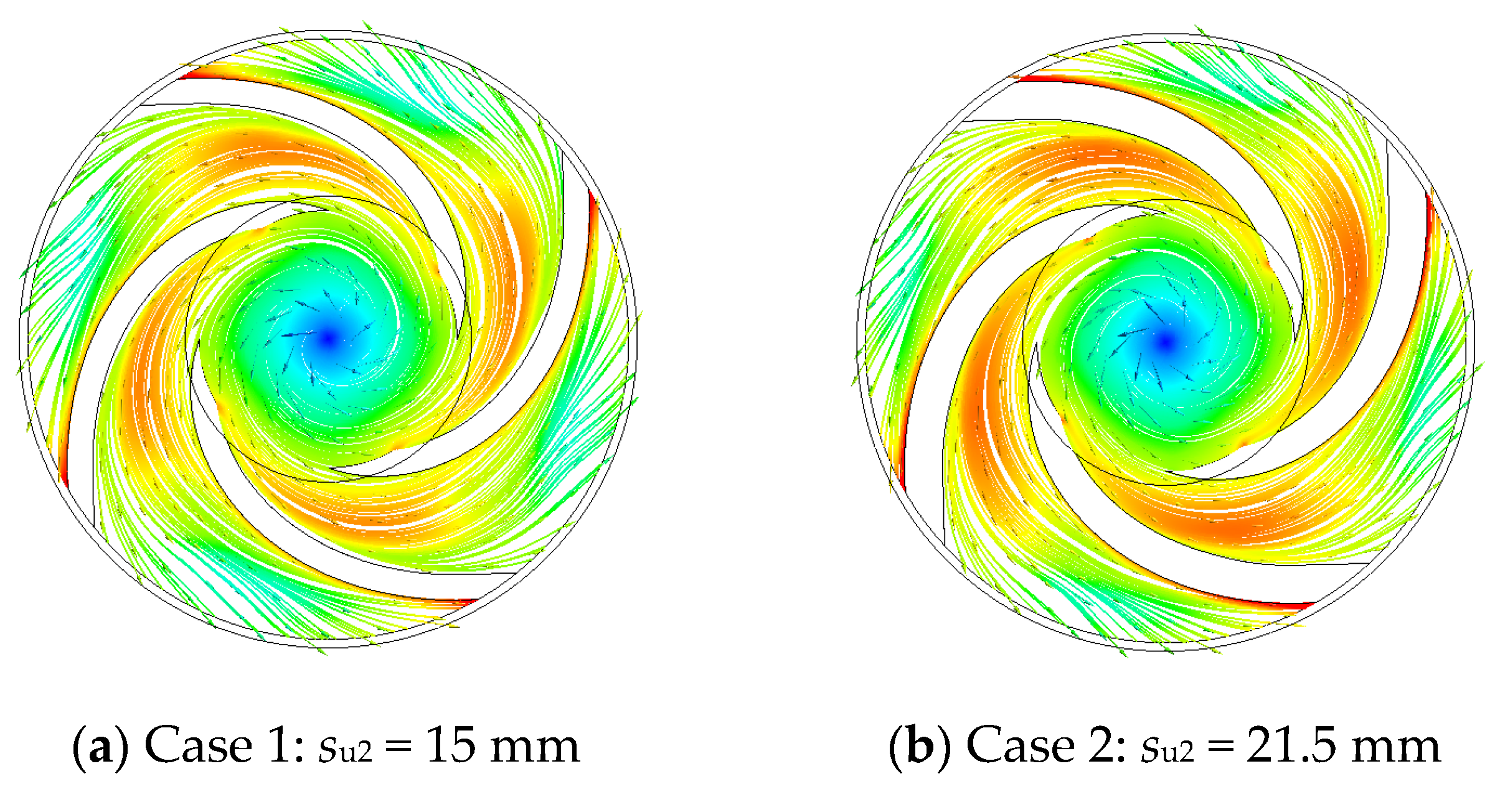
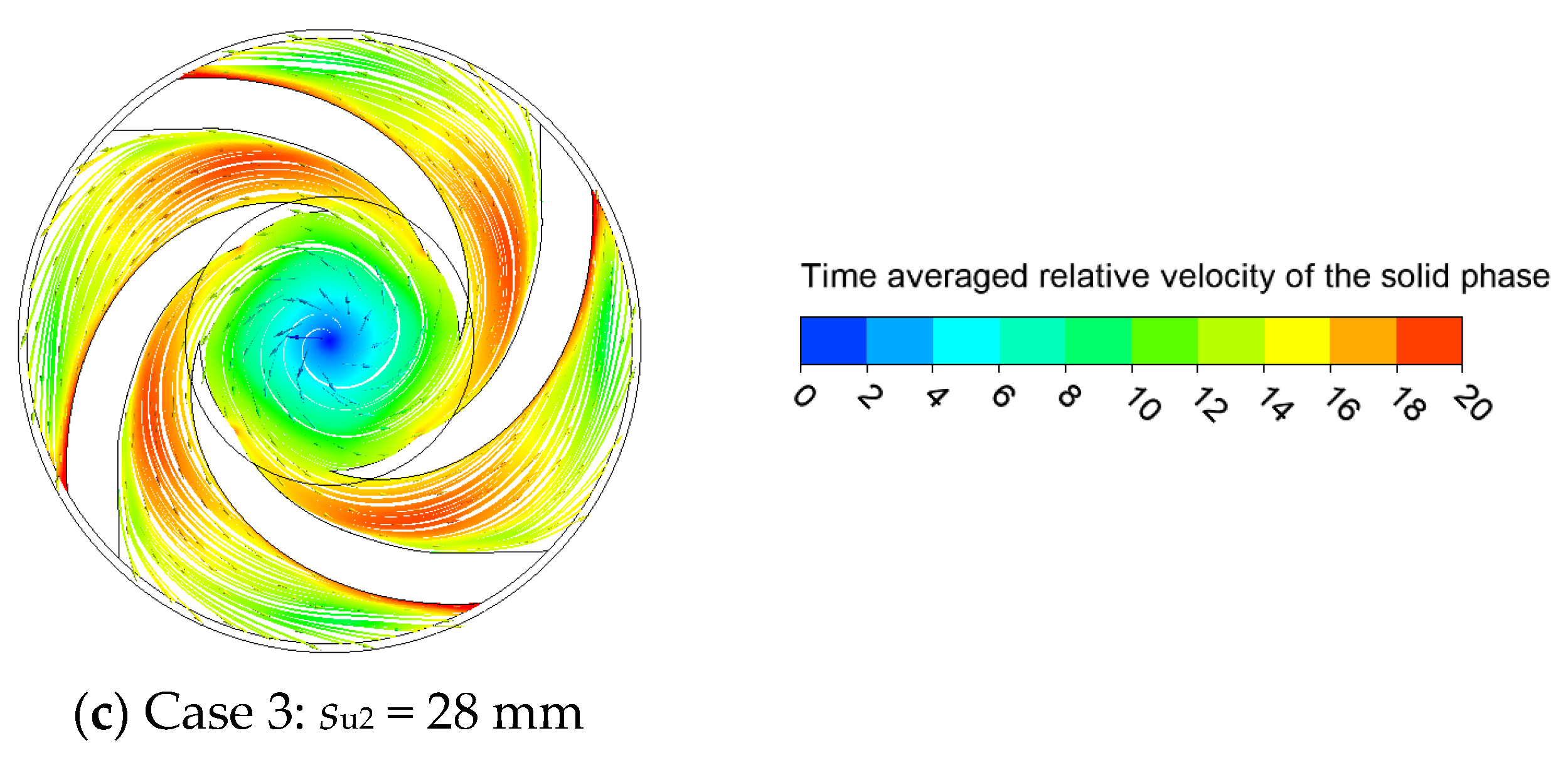
4.2. Streamlines of Time-Averaged Relative Velocity of the Solid Particles on the Impeller Back Shroud
Figure 4 shows the streamlines of the time-averaged relative velocity of the solid particles on the impeller back shroud. In all three impellers, the region with the largest relative velocity of the solid particles occurs on the blade pressure side near the impeller exit. Meanwhile, the thick blade leading edges result in a severe excretion effect, so that there is a region with a relatively high velocity near the impeller inlet. This situation is more obvious as the blade thickness increases. Moreover, it can be obviously observed that the number of streamlines near the suction side increases with increasing blade thickness. Furthermore, the distribution of the streamlines is more uniform, which illustrates that the trajectories of the solid particles are offset towards the suction side. This explains the increasing solid fraction on the suction side in Figure 3.
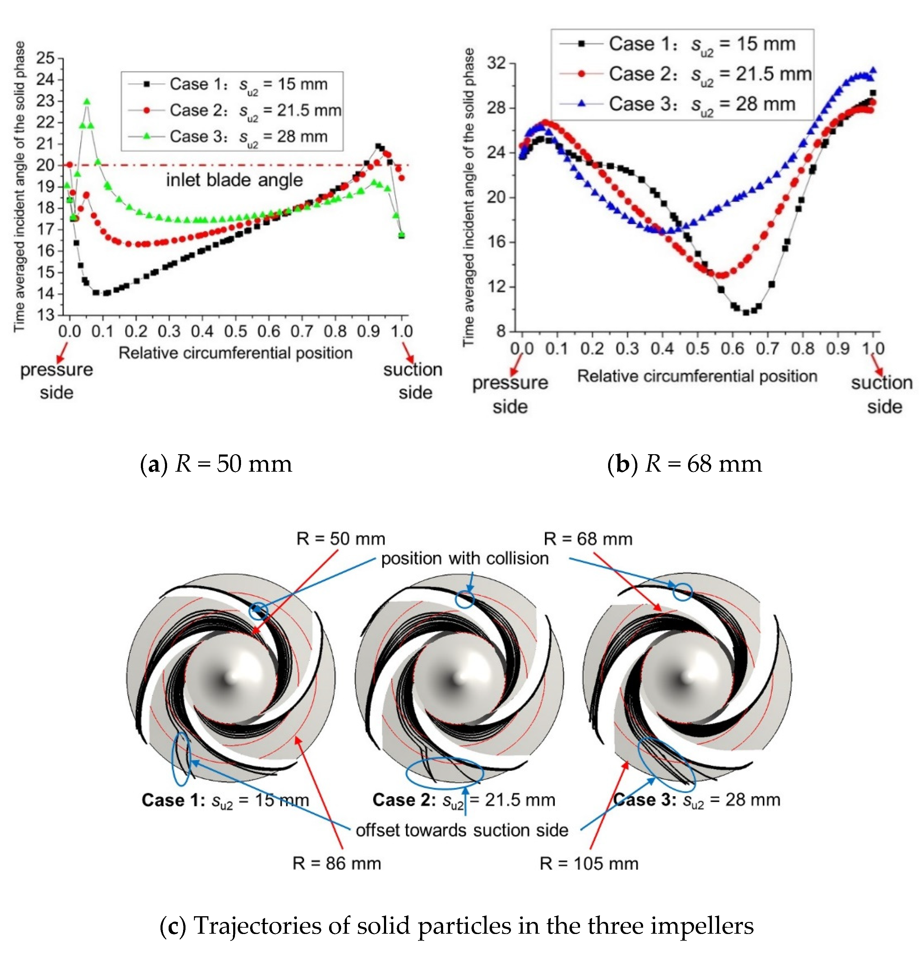
4.3. Time-Averaged Flow Angles of the Solid Particles in the Impeller
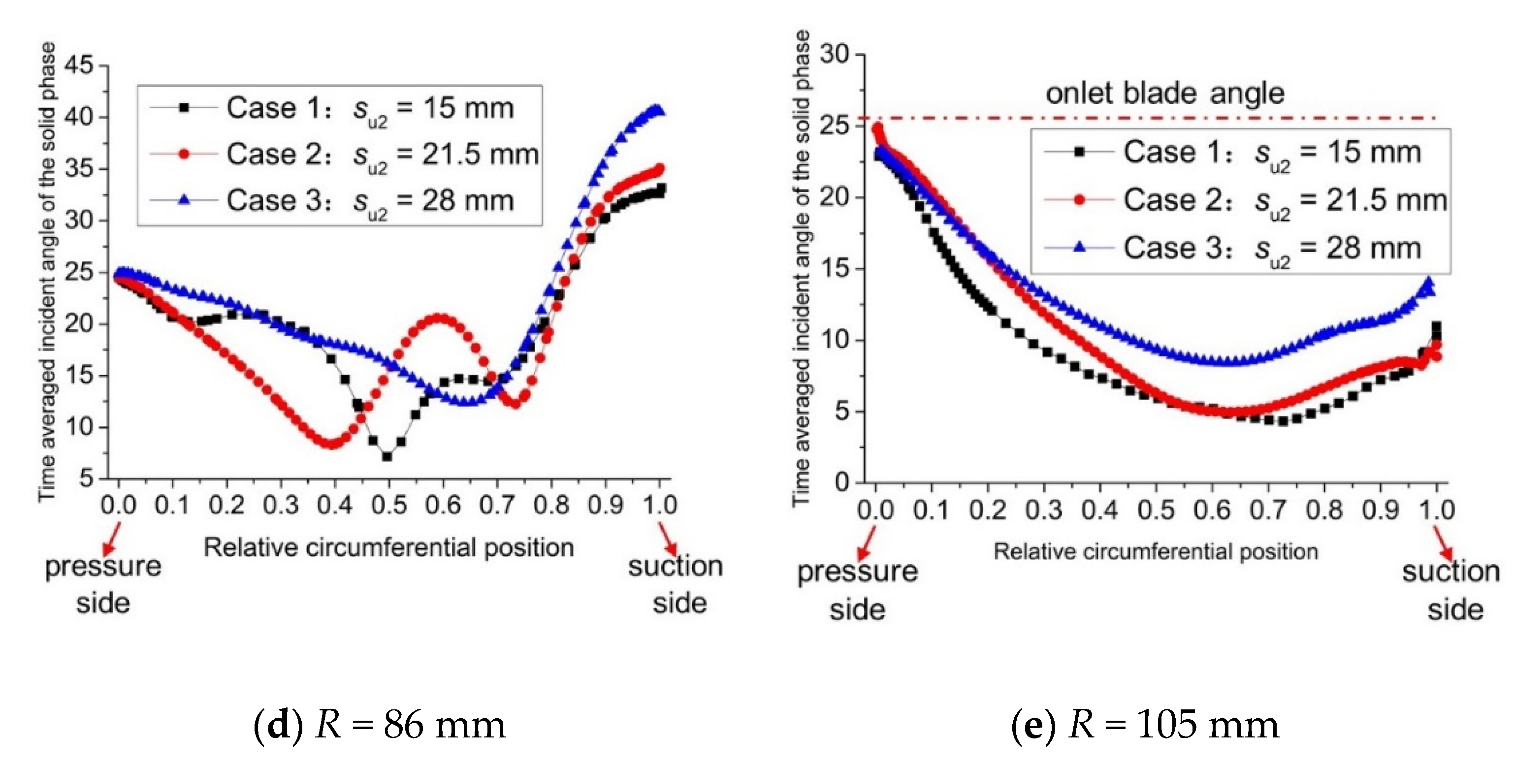
To determine the reason for the offset in the trajectories of solid particles towards the blade suction side with increasing blade thickness, the respective time-averaged flow angles of solid particles at the polylines with radius of 50 mm (impeller inlet), 68 mm, 86 mm, and 105 mm (impeller outlet) were calculated. The absolute velocity and the relative velocity, both of which were time averaged during one impeller period, could be exported by ANSYS CFX directly. Then, the time-averaged flow angles were calculated by Equation (7), and the results are shown in Figure 5. It should be noted that the horizontal ordinate 0 represents the region near the blade pressure side and 1 represents that close to the blade suction side.
As shown in Table 1, all three impellers have the same blade profile of the blade pressure side with an inlet blade angle of 20°. However, it can be observed in Figure 5a that the flow angles of solid particles at the impeller inlet near the blade pressure sides of all three impellers are smaller than 20°. This is because the density of the solid particles is much larger than that of water, thus resulting in a larger inertia force. Under the effect of the large inertia force, the flow angles of solid particles become smaller than the inlet blade angle. Flow angles smaller than the inlet blade angle mean that the solid particles are more likely to collide with the leading edges, thus resulting in severe abrasion of the blade leading edges.
However, the flow angles of solid particles decrease with increasing blade thickness. It should be noted that all three impellers have the same blade profile of the blade pressure side, but the blade thickness is different, which is achieved by modifying the blade profile of the blade suction side. Obviously, when the blade profiles of the blade pressure side are the same, the blade angle at the suction side of the thicker blades will be smaller, which results in more collisions between the particles and the blade suction side.
The flow angles of solid particles at the polylines with radius of 68 mm and 86 mm are both larger than those at the impeller inlet, especially near the blade suction side, as shown in Figure 5b,d. As mentioned above, most of the solid particles collide with the blade leading edges, then the solid particles rebound from the blade pressure side with larger flow angles. The large flow angles of the solid particles mean that the particles move towards the blade suction side, which will cause abrasion of the blade suction side.
The flow angles of solid particles at the impeller exit are smaller than those at the two polylines mentioned above, as shown in Figure 5e. This is due to the large inertia force cause by the large density—the same reasoning as that for the impeller inlet. However, the flow angles of solid particles at the impeller exit near the blade suction side are smaller than those at the impeller inlet. This is because the particles collide with the blade suction side in the region with radius ranging from 68 mm to 86 mm, then the particles rebound from the blade suction side.
Moreover, the flow angles of solid particles at the four polylines all increase with increasing blade thickness. This is because the increase in blade thickness leads to a decrease in the area of flow passages, which results in an increase in vm1. The increase in vm1 leads to an increase in the relative flow angle according to the velocity triangle theory. As shown in Figure 5c, the increase in the flow angles of solid particles results in an increase in the wrap angles of the particle trajectories, which means that the solid particles move towards the blade suction side. Meanwhile, the trajectories with the larger wrap angles delay the time at which the collisions between the solid particles and the blade pressure side take place. As a result, the positions where the collisions take place on the blade pressure side are offset towards the impeller exit, as shown in Figure 5c. The analysis above explains the streamlines that can be observed in Figure 4.
5. Wear Testing
5.1. Test Rig
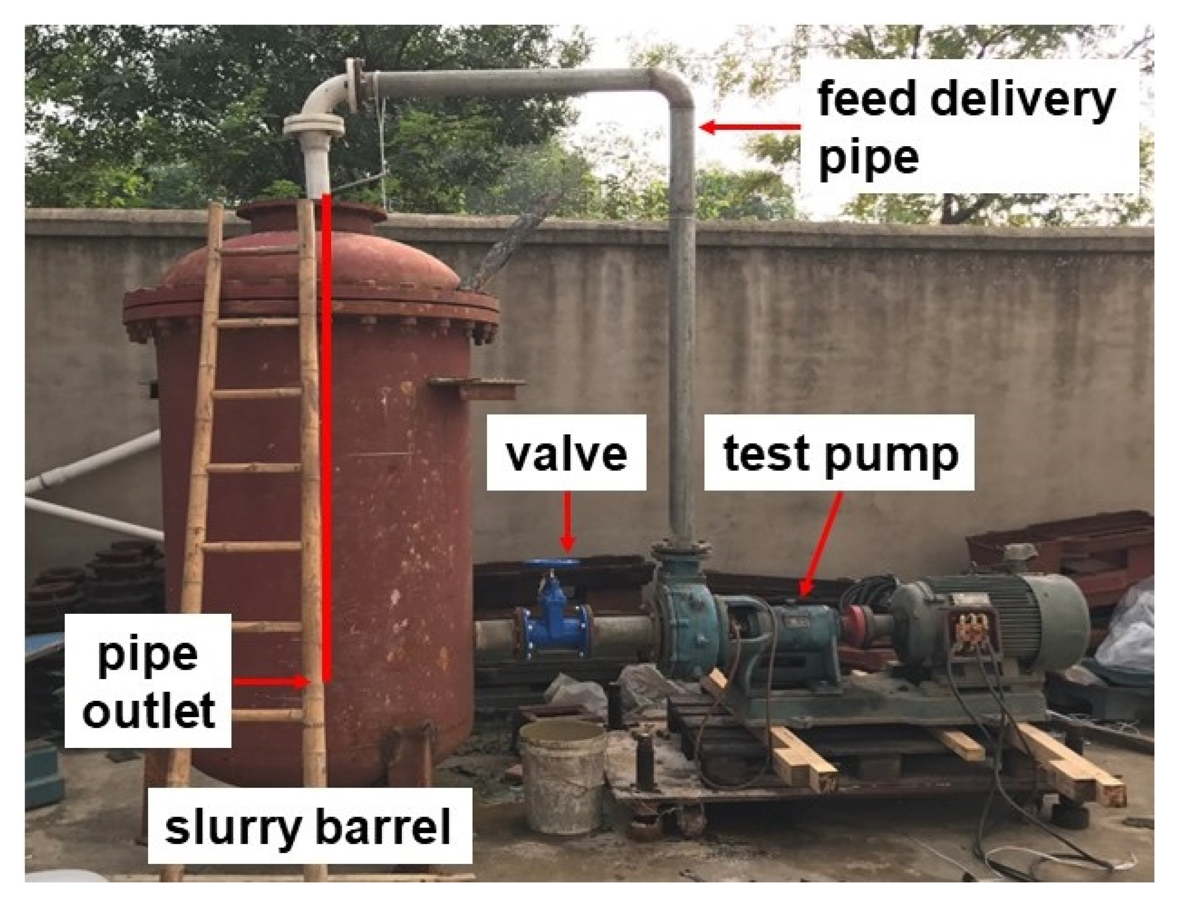
A wear test was conducted for validation of the accuracy of the numerical results and to analyze the wear pattern of the impellers. The impellers of Case 1 and Case 3 were manufactured; these can be seen in Figure 6. The wear test rig consisted of a slurry barrel, feed delivery pipe, valves, and test pump. Due to the lack of a stirrer, the feed delivery pipe extended to the bottom of the slurry barrel for the purpose of stirring. The volume of the slurry barrel was approximately 2 m3. There were four pairs of feed delivery pipes with respective outlet diameters of 40 mm, 50 mm, 65 mm, and 80 mm.
5.2. Test Method
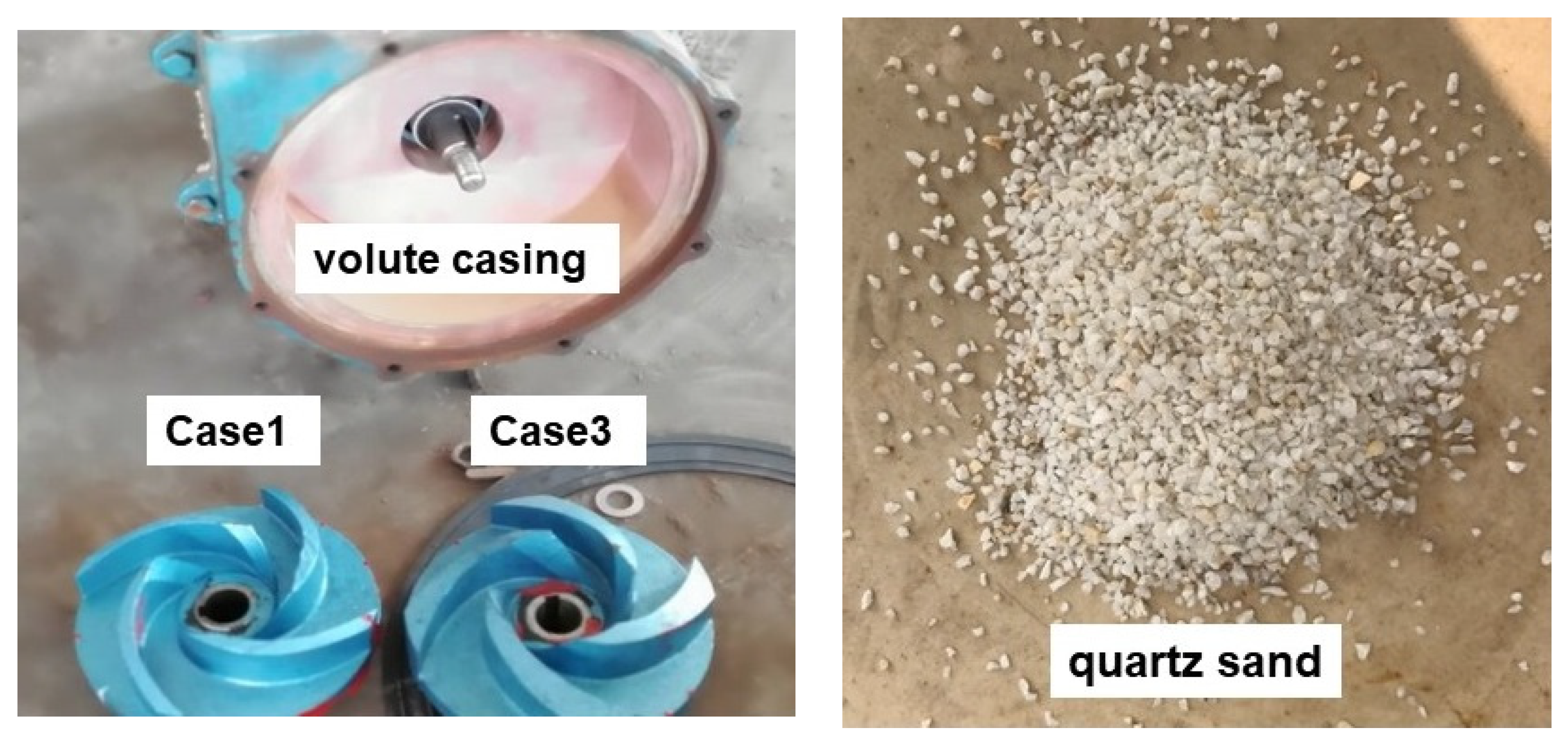
The impellers of Cases 1 and 3 were manufactured for the wear test. The impellers were coated first with red paint and then with blue paint, as shown in Figure 7. Quartz sand with a density of 2650 kg/m3 was used as the abradant. The pump was operated at the rated condition with a solid fraction of 10%. The wear test lasted half an hour.
5.3. Test Results
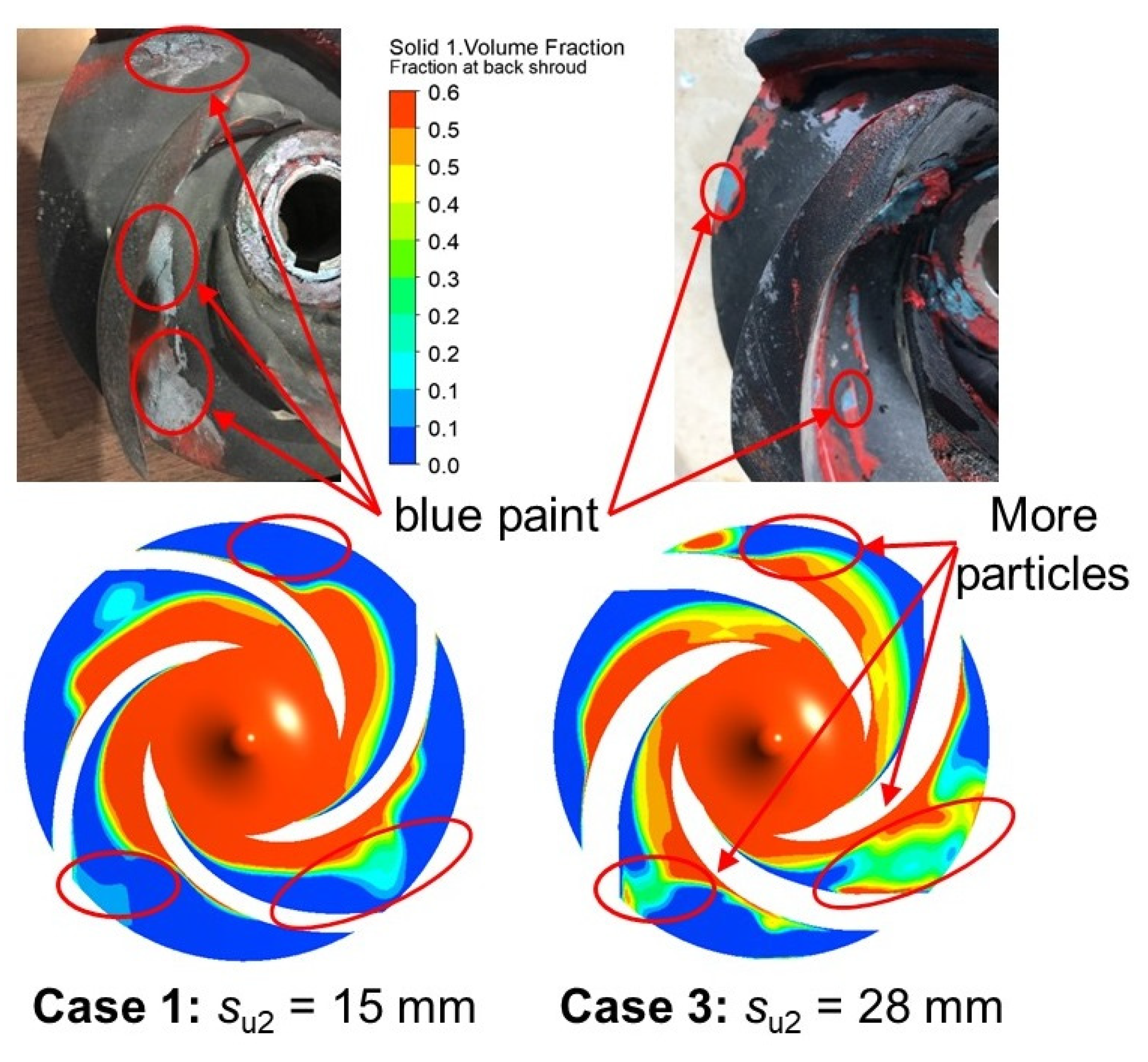
Figure 8 shows the wear patterns on the back shroud of the two manufactured impellers. It can be seen that the paint on the back shroud near the blade pressure side abraded for both impellers. There was a little blue paint left on the back shroud near the blade suction side in the impeller with thinner blades. However, almost no blue paint was left on the back shroud of the impeller with thicker blades. Figure 8 also shows the volume fraction of solid particles on the back shroud. There are more particles occurring at the region close to the blade suction side, especially the posterior flow passages of the impeller with the thicker blades. Hence, the thicker blades led to a more uniform abrasion on the back shroud. From the comparison in Figure 8, we can see that the distribution of the volume fraction of solid particles on the back shroud shows a good agreement with the wear pattern on the back shroud of the tested impellers.
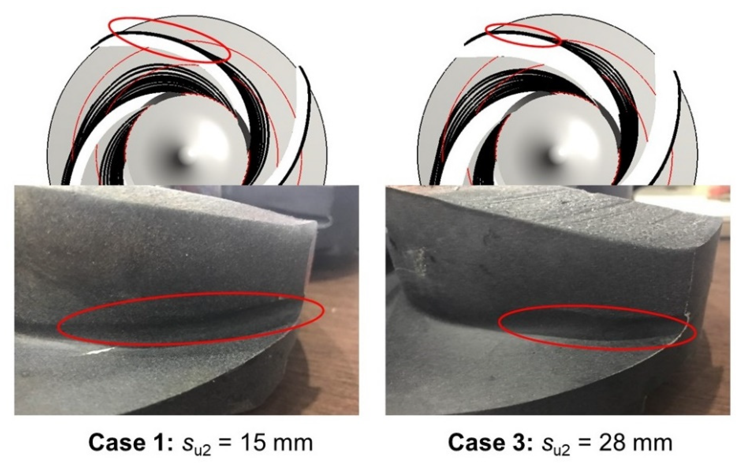
Figure 9 shows the wear patterns on the blade pressure sides. The wear pattern on the pressure side of the impeller with the thinner blades is longer and deeper than that of the impeller with the thicker blades. As mentioned above, the thicker blades lead to larger incident angles of the solid particles, resulting in larger wrap angles of the particle trajectories. The solid particles in the impeller with the thinner blades collide with the blade pressure side earlier in the region near the impeller inlet, as shown in Figure 9. After that, the solid particles colliding with the pressure side may undergo another couple of collisions with the pressure side or slide along the pressure side until they reach the impeller exit, which results in severe abrasion on the blade pressure side. From the comparison in Figure 9, we can see that the trajectories of solid particles show good agreement with the wear patterns on the blade pressure sides of the tested impellers.
Figure 10 shows the wear patterns on the blade suction sides. It can be seen that the abrasion on the blade suction side of the impeller with the thicker blades was more severe. Figure 10 also shows the volume fractions of solid particles on the blade suction sides. There are more solid particles in the posterior region of the blade suction side, thus resulting in more severe abrasion. From the comparison in Figure 10, we can see that the volume fractions of solid particles show good agreement with the wear patterns on the blade suction sides of the tested impellers.
6. Conclusions
In this paper, the effect of blade thickness on the solid–liquid two-phase flow and impeller wear in a ceramic centrifugal slurry pump was numerically and experimentally investigated. The main conclusions are summarized as follows:
- (1)
- As the blade thickness increases, the vm of water increases due to the decrease in the flow area of the impeller passages, resulting in an increase in the relative flow angle. Hence, the incident angles of the solid particles increase under the effect of the flow field, which leads to larger wrap angles of the particle trajectories in the impeller passages.
- (2)
- As the wrap angles of the solid trajectories in the impeller passages increase, it takes a longer time for the solid particles to collide with the blade pressure side, so the region where the collisions take place between the solid particles and the blade pressure side is offset towards the impeller exit.
- (3)
- As the blade thickness increases, the number of solid particles colliding with the blade leading edges decreases, and the particles are more likely to collide with the blade suction side.
- (4)
- Increasing the blade thickness alleviates the abrasion of the leading edges and the pressure side of the impeller blades and makes the abrasion of the back shroud more uniform. However, the blade suction side is abraded more severely, and the hydraulic performance of the pump decreases.
- (5)
- The solid particle volume fractions show good agreement with the wear patterns on the back shroud and the blade suction sides of the tested impellers. Meanwhile, the solid particle trajectories are in accordance with the wear patterns on the blade pressure sides of the tested impellers. These prove that the numerical method adopted in this paper can predict the abrasion of impellers in ceramic slurry pumps.
Author Contributions
Y.T. designed the pump and simulated and analyzed data; Y.B. contributed mesh construction and organized the paper; Y.W. contributed experimental process. All authors have read and agreed to the published version of the manuscript.
Funding
This research was funded by The Natural Science Foundation of the Jiangsu Higher Education Institutions of China (19KJB470032).
Conflicts of Interest
The authors declare no potential conflicts of interest with respect to the research, authorship, and/or publication of this article.
References
- Berenin, V.V. Ceramic centrifugal pumps for the chemical and petroleum industries. Chem. Pet. Eng. 2002, 38, 472–475. [Google Scholar] [CrossRef]
- Tao, Y.; Yuan, S.; Liu, J.; Zhang, F.; Tao, J. Influence of blade thickness on transient flow characteristics of centrifugal slurry pump with semi-open impeller. Chin. J. Mech. Eng. 2016, 29, 1209–1217. [Google Scholar] [CrossRef]
- Cavazzini, G.; Pavesi, G.; Santolin, A.; Ardizzon, G.; Lorenzi, R. Using splitter blades to improve suction performance of centrifugal impeller pumps. Proc. Inst. Mech. Eng. Part A J. Power Energy 2015, 229, 309–323. [Google Scholar] [CrossRef]
- Li, S.; Wu, P.; Wu, D. Hydraulic optimization and loss analyses of a low specific-speed centrifugal pump with variable-thickness blades. In Proceedings of the ASME 2016 Fluids Engineering Division Summer Meeting, Washington, DC, USA, 10–14 July 2016. [Google Scholar]
- Gao, B.; Zhang, N.; Li, Z.; Ni, D.; Yang, M. Influence of the blade trailing edge profile on the performance and unsteady pressure pulsations in a low specific speed centrifugal pump. ASME J. Fluids Eng. 2016, 138, 051106. [Google Scholar] [CrossRef]
- Kim, Y.I.; Kim, S.; Yang, H.M.; Lee, K.Y.; Choi, Y.S. Analysis of internal flow and cavitation characteristics for a mixed-flow pump with various blade thickness effects. J. Mech. Sci. Technol. 2019, 33, 3333–3344. [Google Scholar] [CrossRef]
- Kim, S.J.; Choi, Y.S.; Cho, Y.; Choi, J.W.; Kim, J.H. Effect of runner blade thickness on flow characteristics of a francis turbine model at low flowrates. ASME J. Fluids Eng. 2020, 142, 031104. [Google Scholar] [CrossRef]
- Wu, C.; Zhang, W.; Wu, P.; Yi, J.; Ye, H.; Huang, B.; Wu, D. Effects of blade pressure side modification on unsteady pressure pulsation and flow structures in a centrifugal pump. ASME J. Fluids Eng. 2021, 143, 111208. [Google Scholar] [CrossRef]
- Chang, H.; Li, W.; Shi, W.; Liu, J. Effect of blade profile with different thickness distribution on the pressure characteristics of novel self-priming pump. J. Braz. Soc. Mech. Sci. Eng. 2018, 40, 518. [Google Scholar] [CrossRef]
- Jin, Y.X.; Song, W.W.; Jie, F. A study on the effects of blade thickness on the performance of low specific speed centrifugal pump. Adv. Mater. Res. 2015, 1070–1072, 1957–1962. [Google Scholar] [CrossRef]
- Tao, Y.; Yuan, S.; Liu, J.; Zhang, F.; Tao, J. The influence of the blade thickness on the pressure pulsations in a ceramic centrifugal slurry pump with annular volute. Proc. Inst. Mech. Eng. Part A J. Power Energy 2017, 231, 415–431. [Google Scholar] [CrossRef]
- Qian, B.; Wu, P.; Huang, B.; Zhang, K.; Li, S.; Wu, D. Optimization of a centrifugal impeller on blade thickness distribution to reduce hydro-induced vibration. ASME J. Fluids Eng. 2020, 142, 021202. [Google Scholar] [CrossRef]
- Deng, Q.; Song, W.; Zhou, Y.; Su, K.; Tao, C. Research on the influence of cooperative design of blade number and blade thickness on the characteristics of the centrifugal pump. China Rural Water Hydropower 2021, 2021, 31–36. [Google Scholar]
- Cheng, W.; Gu, B.; Shao, C.; Wang, Y. Hydraulic characteristics of molten salt pump transporting solid-liquid two-phase medium. Nucl. Eng. Des. 2017, 324, 220–230. [Google Scholar] [CrossRef]
- Tarodiya, R.; Gandhi, B.K. Numerical simulation of a centrifugal slurry pump handling solid-liquid mixture: Effect of solids on flow field and performance. Adv. Powder Technol. 2019, 30, 2225–2239. [Google Scholar] [CrossRef]
- Peng, G.; Huang, X.; Zhou, L.; Zhou, G.; Zhou, H. Solid-liquid two-phase flow and wear analysis in a large-scale centrifugal slurry pump. Eng. Fail. Anal. 2020, 114, 104602. [Google Scholar] [CrossRef]
- Wang, Y.; Chen, B.; Zhou, Y.; Ma, J.; Zhang, X.; Zhu, Z.; Li, X. Numerical simulation of fine particle solid-liquid two-phase flow in a centrifugal pump. Shock. Vib. 2021, 2021, 6631981. [Google Scholar]
- Huang, S.; Zou, W.L.; Zhou, J.J.; He, D.P.; Peng, T.Y. Unsteady numerical simulation on solid-liquid flows and wear in a centrifugal pump based on DPM model. China Rural Water Hydropower 2016, 44, 103–106. [Google Scholar]
- Lai, F.; Wang, Y.; EI-Shahat, S.A.; Li, G.; Zhu, X. Numerical study of solid particle erosion in a centrifugal pump for liquid-solid flow. ASME J. Fluids Eng. 2019, 141, 121302. [Google Scholar] [CrossRef]
- Wang, Y.; Han, C.; Zhou, Y.; Lin, Z.; Ma, J.; Li, X.; Zhang, W. Wear characteristics of dense fine particles solid-liquid two-phase fluid centrifugal pump with open impellers. Shock. Vib. 2021, 2021, 6635630. [Google Scholar]
- Huang, S.; Su, X.; Qiu, G. Transient numerical simulation for solid-liquid flow in a centrifugal pump by DEM-CFD coupling. Eng. Appl. Comput. Fluid Mech. 2015, 9, 411–418. [Google Scholar] [CrossRef] [Green Version]
- Huang, S.; Huang, J.; Guo, J.; Mo, Y. Study on wear properties of the flow parts in a centrifugal pump based on EDEM-Fluent coupling. Processes 2019, 7, 431. [Google Scholar] [CrossRef] [Green Version]
- Shao, W.; Zhao, R.; Zhang, D. Erosion of multistage mixed flow pump based on fully coupled CFD-DEM method. Chin. J. Hydrodyn. 2020, 35, 640–648. [Google Scholar]
- Li, Y.; Yuan, S.; Wang, X.; Keat Tan, S.; Mao, J. Comparison of flow fields in a centrifugal pump among different tracer particles by particle image velocimetry. ASME J. Fluids Eng. 2016, 138, 061105. [Google Scholar] [CrossRef]
- Shi, B.; Wei, J.; Zhang, Y. A novel experimental facility for measuring internal flow of solid-liquid two-phase flow in a centrifugal pump by PIV. Int. J. Multiph. Flow 2017, 89, 266–276. [Google Scholar] [CrossRef]
- Tan, M.; Zhang, K.; Wu, X.; Liu, H. Experimental study on large particle solid-liquid two-phase flow in a centrifugal pump. Trans. Chin. Soc. Agric. Eng. 2021, 37, 62–67. [Google Scholar]
Figure 1.
Geometric configuration of each examined case.

Figure 2.
Computational domain and grid meshing.

Figure 3.
Contours of the time-averaged solid fraction on the surfaces of the impeller blades.

Figure 4.
Streamlines of time-averaged relative velocity of the solid particles on the impeller back shroud.
Figure 4.
Streamlines of time-averaged relative velocity of the solid particles on the impeller back shroud.


Figure 5.
Time-averaged flow angles of solid particles in the three impellers.


Figure 6.
Wear test rig.

Figure 7.
Manufactured impellers and abradant.

Figure 8.
Comparison of the solid volume fractions and the wear patterns on the back shrouds of the tested impellers.
Figure 8.
Comparison of the solid volume fractions and the wear patterns on the back shrouds of the tested impellers.

Figure 9.
Comparison of the solid particle trajectories and the wear patterns on the pressure sides of the tested impellers.
Figure 9.
Comparison of the solid particle trajectories and the wear patterns on the pressure sides of the tested impellers.

Figure 10.
Comparison of the solid volume fractions and the wear patterns on the suction sides of the tested impellers.
Figure 10.
Comparison of the solid volume fractions and the wear patterns on the suction sides of the tested impellers.


Table 1.
Main geometric dimensions.
| Description | Parameter | Value |
|---|---|---|
| Suction branch diameter | Ds | 100 mm |
| Discharge branch diameter | Dd | 80 mm |
| Impeller eye diameter | D1 | 90 mm |
| Impeller exit diameter | D2 | 210 mm |
| Leading edge width | b1 | 41 mm |
| Trailing edge width | b2 | 28 mm |
| Inlet blade angle | β1 | 20° |
| Outlet blade angle | β2 | 26° |
| Blade wrap angle | φ | 120° |
| Back blade width | bb | 5 mm |
| Volute chamber width | b3 | 63 mm |
| Diameter to volute tongue | D3 | 287 mm |
Table 2.
GCI test on grids.
| Grid Number | 2,071,856 | 3,115,696 | 4,021,768 | 5,013,874 |
| Head H/m | 47.38 | 48.02 | 48.43 | 48.61 |
| GCI/% | 6.26 | 4.71 | 2.47 | 2.03 |
Publisher’s Note: MDPI stays neutral with regard to jurisdictional claims in published maps and institutional affiliations. |
© 2021 by the authors. Licensee MDPI, Basel, Switzerland. This article is an open access article distributed under the terms and conditions of the Creative Commons Attribution (CC BY) license (https://creativecommons.org/licenses/by/4.0/).
Share and Cite
MDPI and ACS Style
Tao, Y.; Bai, Y.; Wu, Y. Influence of Blade Thickness on Solid–Liquid Two-Phase Flow and Impeller Wear in a Ceramic Centrifugal Slurry Pump. Processes 2021, 9, 1259. https://doi.org/10.3390/pr9081259
AMA Style
Tao Y, Bai Y, Wu Y. Influence of Blade Thickness on Solid–Liquid Two-Phase Flow and Impeller Wear in a Ceramic Centrifugal Slurry Pump. Processes. 2021; 9(8):1259. https://doi.org/10.3390/pr9081259
Chicago/Turabian StyleTao, Yi, Yongming Bai, and Yingchun Wu. 2021. "Influence of Blade Thickness on Solid–Liquid Two-Phase Flow and Impeller Wear in a Ceramic Centrifugal Slurry Pump" Processes 9, no. 8: 1259. https://doi.org/10.3390/pr9081259
Note that from the first issue of 2016, this journal uses article numbers instead of page numbers. See further details here.