
Analysis and Design of a Standalone Electric Vehicle Charging Station Supplied by Photovoltaic Energy


1
Electrical Engineering Department, Faculty of Engineering, University of Tabuk, Tabuk 47913, Saudi Arabia
2
Electrical Engineering Department, College of Engineering, Taif University, Taif 21944, Saudi Arabia
3
Electrical Engineering Department, Faculty of Engineering, Cairo University, Cairo 12613, Egypt
4
Renewable Energy & Energy Efficiency Centre (REEEC), University of Tabuk, Tabuk 47913, Saudi Arabia
*
Author to whom correspondence should be addressed.
Processes 2021, 9(7), 1246; https://doi.org/10.3390/pr9071246
Submission received: 4 July 2021
/
Revised: 16 July 2021
/
Accepted: 16 July 2021
/
Published: 19 July 2021
(This article belongs to the Special Issue Modelling, Monitoring, Control and Optimization for Complex Industrial Processes)
Abstract
:Nowadays, there is a great development in electric vehicle production and utilization. It has no pollution, high efficiency, low noise, and low maintenance. However, the charging stations, required to charge the electric vehicle batteries, impose high energy demand on the utility grid. One way to overcome the stress on the grid is the utilization of renewable energy sources such as photovoltaic energy. The utilization of standalone charging stations represents good support to the utility grid. Nevertheless, the electrical design of these systems has different techniques and is sometimes complex. This paper introduces a new simple analysis and design of a standalone charging station powered by photovoltaic energy. Simple closed-form design equations are derived, for all the system components. Case-study design calculations are presented for the proposed charging station. Then, the system is modeled and simulated using Matlab/Simulink platform. Furthermore, an experimental setup is built to verify the system physically. The experimental and simulation results of the proposed system are matched with the design calculations. The results show that the charging process of the electric vehicle battery is precisely steady for all the PV insolation disturbances. In addition, the charging/discharging of the energy storage battery responds perfectly to store and compensate for PV energy variations.
1. Introduction
Nowadays, classical internal combustion engine (ICE) vehicles are being replaced by electric vehicles (EVs) [1,2]. In fact, the ICEs have many drawbacks that can be mitigated by EVs. The EVs have negligible pollution, higher energy efficiency, lower noise, and lower maintenance compared to the ICE. However, the charging process of the EV battery still has many obstacles such as the charging time, the charging station’s infrastructure, and the effect of these stations on the present electrical power system. The charging time can be greatly reduced to minutes by utilizing fast charging techniques [3,4,5]. These techniques represent large electrical loads on the utility grid and affect it adversely. Especially, when there is a high number of charging stations connected simultaneously to the utility grid, many problems would be generated such as excessive overload, voltage instability, and voltage variation [6,7,8]. One of the solutions to these problems is the upgrading of the power system but this will lead to high costs. Another better solution is the use of an energy storage system (ESS) that can act as a buffer between the EV charging station (EVCS) and the utility [9,10,11,12]. Nevertheless, the use of ESS will reduce slightly the stress on the utility grid but the expected large number of EVCSs in the future is still a challenge.
The idea that the EV is an environmentally friendly vehicle could not be accepted if the charging stations rely mainly on the grid power that is usually generated from fossil fuels. Hence, renewable energy sources must be utilized in EV charging stations to emphasize the environmental impacts of the EV. Usually, renewable energy sources are not continuous, it is intermittent. Hence, there is another use for the ESSs in resolving the discontinuity in these sources.
The common renewable energy sources used for the EV charging stations are photovoltaic (PV), biogas, and wind systems [13,14]. The PV energy systems are simple and have higher efficiency than the wind energy systems. Hence, PV energy is more attractive for EV charging stations. Several research papers have been introduced for the PV-based charging stations [15,16]. Ref. [17] has been proposed a high-power EV charging station utilizing PV powered bidirectional charger. Nevertheless, the proposed system could not permit AC charging. Ref. [18], has suggested an integrated PV panel using a multiport converter for the EV charging station. However, the grid current is greatly distorted. Ref. [19] has introduced a PV-powered grid-tied EV charger via a z-source converter. Though the charger gave better performance, it is not suitable for standalone operation. Therefore, it cannot provide EV charging in absence of a grid. A hybrid optimized management for the ESS of a PV-powered EV station is discussed in [20]. Ref. [21] provides an optimization study on the physical scheduling of the EV charging stations. Ref. [22] has presented a PV-based charging station with an ESS to support the system during peak load. In Ref. [23], a new energy management procedure was introduced for use with small EVs in urban environments. Another strategy, in [24], for the EV charging station power management was proposed to reduce the power consumption from utility grid. Furthermore, the strategy serves to store PV energy when the EV is not online with the utility grid. In Ref. [25], a 20 kW charging station for the EVs was designed and introduced using biogas.
In this paper, a new simple analysis and design of a standalone charging station powered by photovoltaic energy. Based on the assumptions, new closed-form equations are derived for the design purpose. The idea of the analysis and the assumptions are new. Modeling, simulation, and experimental verification are carried out to justify the analysis and the design procedure. Simple energy management is tested practically and simulated. The proposed system includes PV panels, a lithium-ion battery representing the electric vehicle EV, and a lead-acid battery representing the energy storage system. A bidirectional converter is employed for charging/discharging the lead-acid battery and a unidirectional converter is utilized for charging the electric vehicle. A new and simple analysis technique is proposed. In addition, simple design equations are generated from the analysis. The proposed system has been implemented physically and simulated using Matlab/Simulink platform. A single-chip PIC18F4550 microcontroller is utilized to realize the operation of the system. The system is tested successfully for 120 W level and it can be extended for a higher power. Besides, it can be applied in urban and remote areas as well. The objectives of this research are:
- Introducing a novel and simple analysis of the energy and power relations of the charging station powered by photovoltaic energy. The analyses produce closed-form equations for the power and energy of the different system components. In addition, relations for the battery state of charge (SOC) and maximum stored energy of the ESS are derived.
- Designing the charging station components with the help of the derived equations in the analysis part. The design includes the power electronic converters used. Further, case study design calculations are provided.
- Simulating and practically implementing the proposed system. Hence, the system performances are studied indicating the effect of solar energy variations on the system response.
The paper structure is as follows: Section 2 presents the proposed system architecture. Analysis and design of the charging station have been described in Section 3. Section 4 presents the charging converters modelling and design. The proposed control system is shown in Section 5. Section 6 presents the proposed system design. The simulation and experimental results have been discussed in Section 7. Finally, Section 8 comes with the conclusions.
2. The Proposed Charging Station Description
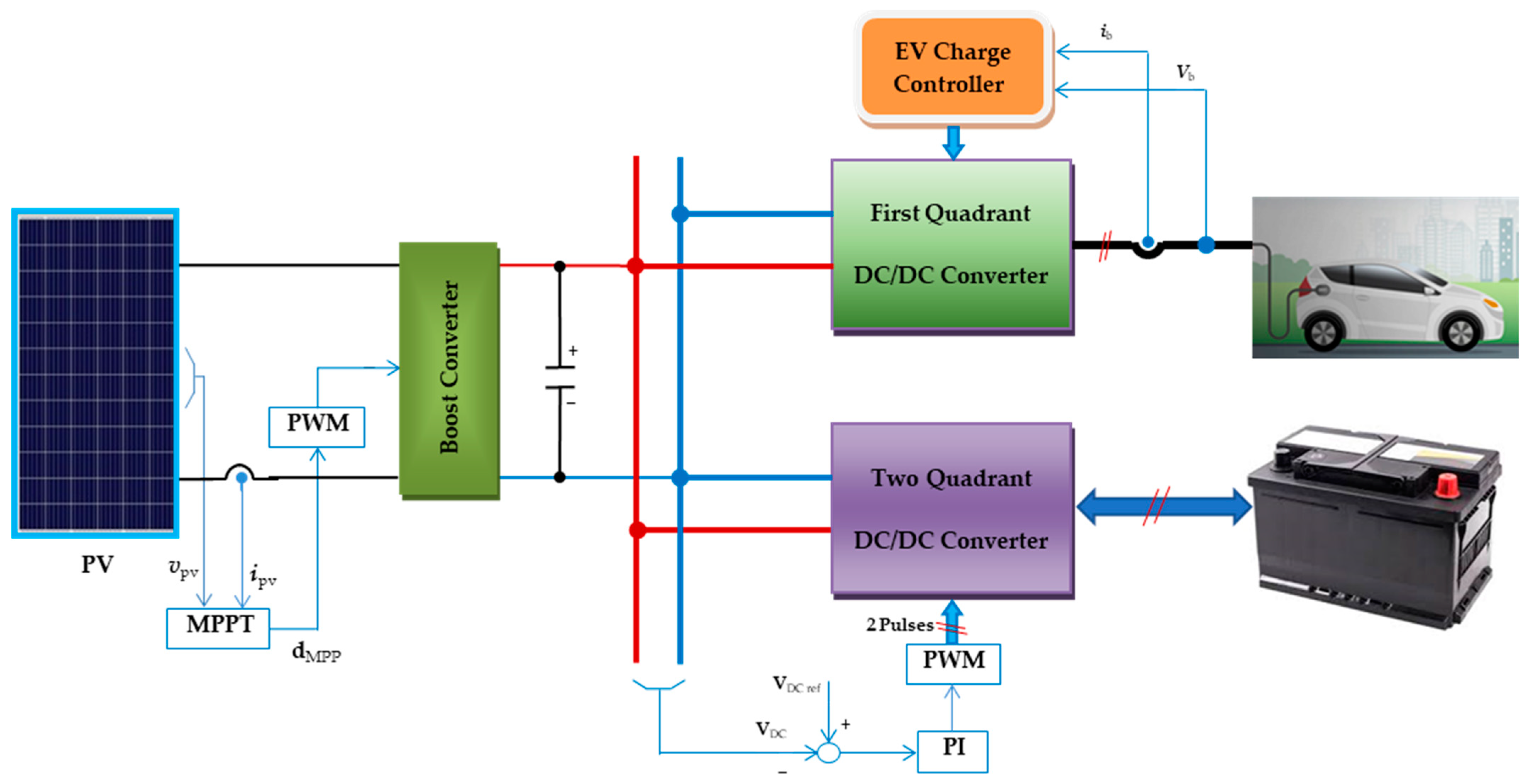
The architecture of the proposed EVCS system is shown in Figure 1. The EVCS system is an off-grid type that is powered by solar energy. It is collected by a PV array that generates electrical energy to the EVCS. The PV panel represents the main source of energy for the charging station. However, the generated energy is not steady. It varies according to the solar insolation level and other environmental issues. Hence, ESS batteries are usually used to compensate for the problem of energy intermittence. The output terminals of the PV are connected to a boost converter. Its function is to match the PV voltage level to that of the DC bus and helps in utilizing the maximum power point tracking (MPPT) condition of the PV panel. Two charging converters are connected to the DC bus namely the EV charger and the energy storage converter. These converters are generally DC/DC converters. However, the EV charger is a one quadrant buck converter that is used to charge the EV battery (lithium-ion). It serves in regulating the charging process of the EV battery. However, the energy storage converter is a two-quadrant DC/DC converter. It is used to control the charge/discharge process of the storage battery (lead-acid). In addition, it participates in regulating the DC bus voltage against the variations of the EV load and insolation level. The modelling and theory of operation of these converters will be explained in the next paragraphs.
3. Analysis and Design of the Charging Station
The electrical design of the EVSC means designing all electrical parts of the station such as the PV array, the system converters, the DC bus voltage level, all passive components, and the storage battery. Many aspects must be considered in designing the EVSC:
- The available solar energy on the site and the maximum permissible area for the PV panels.
- The station power is related to the number of EVs to be charged simultaneously. The charging rate is an important issue that affects the charging time. For fast charging, the station should be capable of charging rates of 3 C to 5 C [26].
- The size of the ESS depends on the available PV power and the demand load of the EV.
As a first step for the design process, the relation among the input solar energy, the output charging power to the EV, and the stored energy in the ESS must be studied. The system power and energy relations will be studied in the next subsection.
3.1. Power and Energy Analysis of the System
In this section, the energy and power relations of the system are derived to help in the design process. The assumptions used in this regard are:
- The storage battery’s initial energy is “Ei” in Wh.
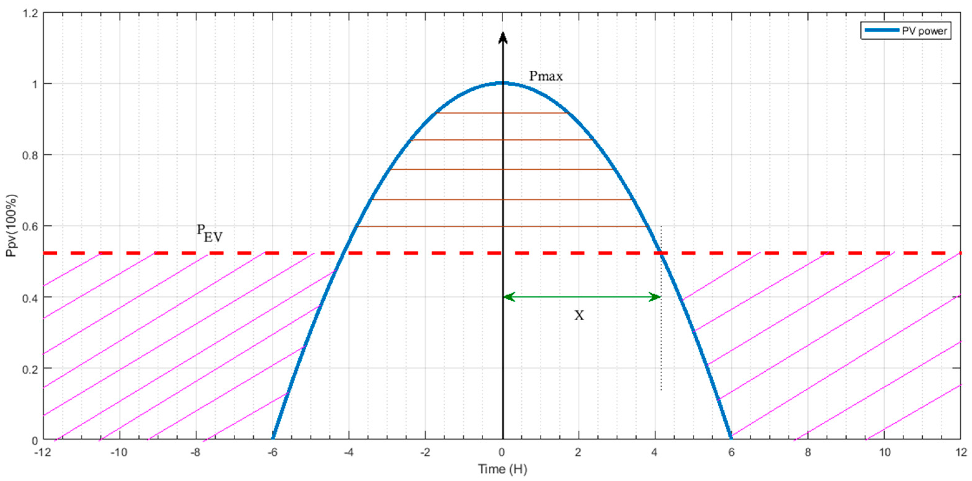
- The output power of the EV station “PEV” is constant.
- The solar power “Ppv” of the PV panel changes with time according to:
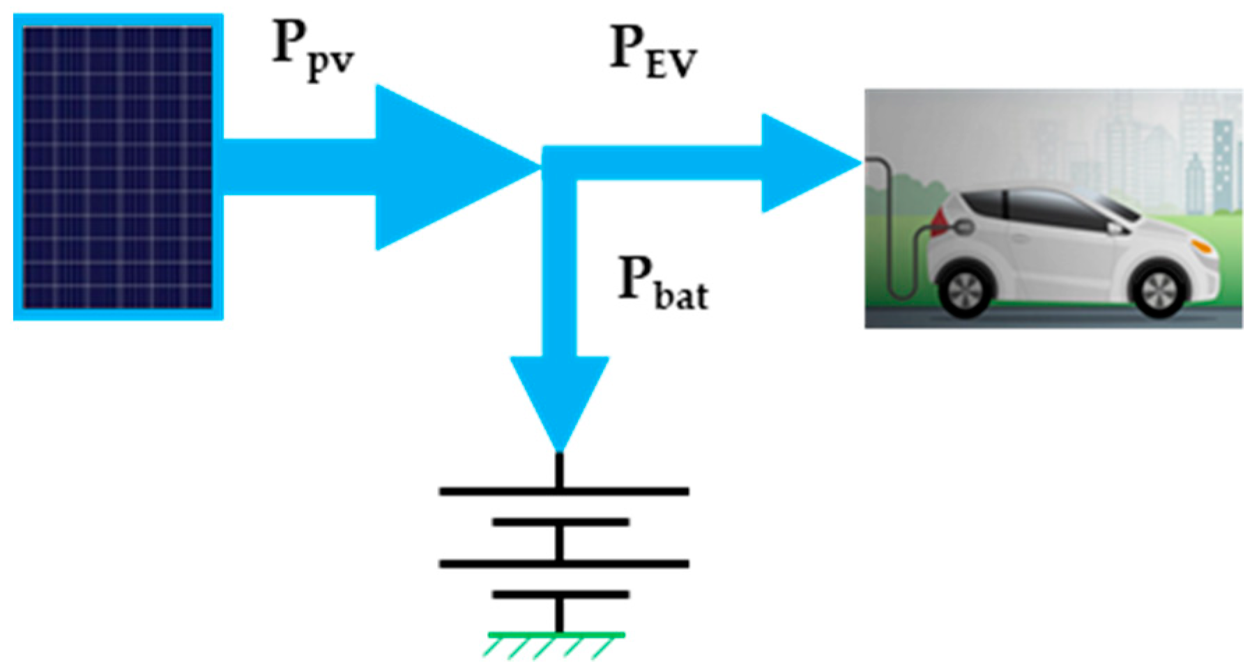
From the power balance principle and refer to the system power flow diagram shown in Figure 3.
Hence,
where; “Pbat” is the instantaneous storage battery power. The average power of the storage battery is assumed to be zero along one day period (T = 24 h).
Hence,
Hence,
Battery state of charge and maximum stored energy
The battery energy-stored can be calculated through:
where; “C” is a constant.
The region ()
Substitute Equation (3) into Equation (7) and integrate:
To get the constant “C”, we have that at t = −6 → . Using Equation (8):
The instantaneous battery energy is given by:
The final value of the energy at this region (t = 6):
This value is the initial value for the next region.
The region (6
)
From Equations (7) and (3):
where; “C1” is constant. From Equations (11) and (12):
Hence,
The maximum stored energy occurs at t = x as shown in Figure 3. It can be shown that the maximum stored energy is given by:
From this analysis, if the EV power PEV is known, then using Equations (1), (6) and (15) the PV power rating and the ESS size can be determined. Hence, the PV array area can be calculated.
4. Charging Converters Modelling and Design
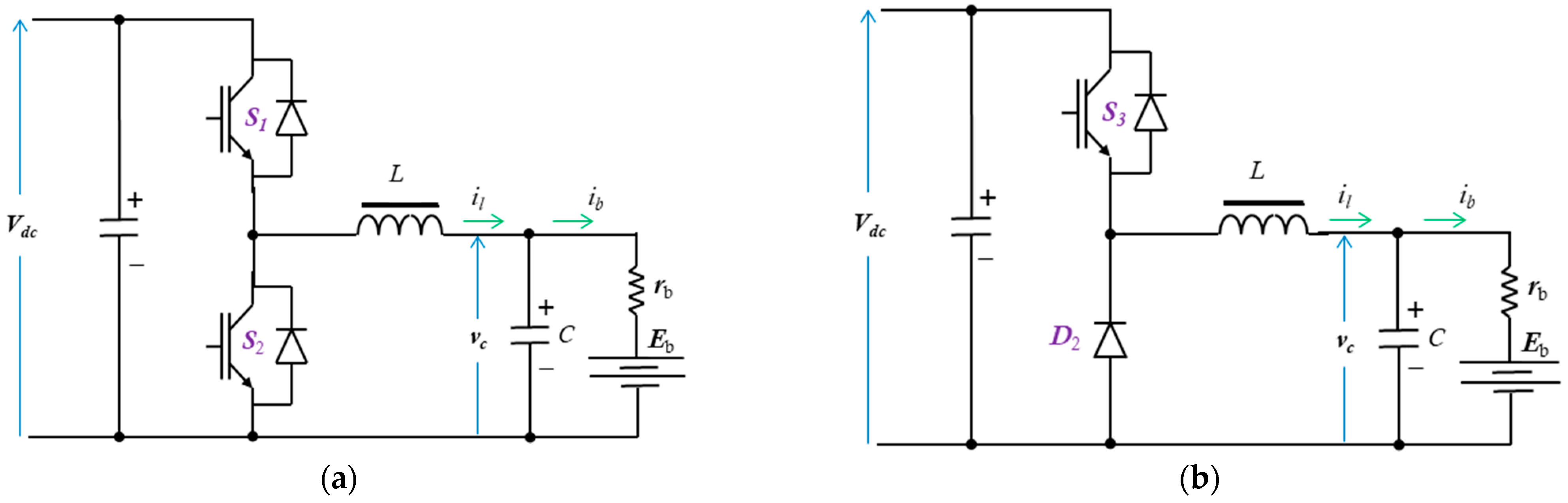
The proposed system has two charging converters. The EV charging converter is a simple buck converter (first-quadrant converter). However, the energy storage battery is a buck-boost converter (two-quadrant converter). The circuit diagrams of the converters are shown in Figure 4. The operation, modeling, and analysis of the two-quadrant converter include that of the first-quadrant converter. The continuous mode is assumed for the converter operation. The converter comprised two IGBT’s (S1, S2), two antiparallel diodes, and an LC filter. The converter terminals are connected to the DC bus and the storage battery. The battery’s internal voltage and resistance are represented by (Eb, rb). The filter inductance is assumed to be large enough to preserve sufficient energy to charge or discharge the battery. Hence, the discontinuous conduction operation mode is neglected. The converter has two modes namely the buck mode and boost mode. The bidirectional converter serves in the boost mode, when the switch S2 is active and the switch S1 acts as a diode, for discharging the battery. However, it serves in the buck mode, when switch S1 is active and the switch S2 acts as a diode, resulting in the battery charge mode. The converter dynamic model in the state-space form is described as:
During buck operation:
where; (il, vc) are the inductor current and the capacitor voltage, u1 represents the switch S1 action with PWM taking values from the set of {0:1}, (L, C) are inductance and the capacitance of the filter, Vdc is the DC bus voltage.
During boost operation:
where; u2 represents the switch S2 action with PWM taking values from the set of {0:1}.
The filter inductor and capacitor design equations are [27]:
where; (dmin, dmax) is the minimum and maximum duty cycle, is the approximate equivalent resistance of Li-ion battery, f is the switching frequency, (, ) is the minimum and maximum ripple currents, r is the minimum voltage ripple factor, and is the maximum battery current.
The DC bus voltage level is selected according to the charging state of the system as the system converters operate in the buck mode. In this case, the DC bus voltage must be greater than the converter output average voltage. On the other hand, the minimum duty cycle and battery voltage variations affect the value of Vdc. These constraints can be written as:
where; () is the battery minimum and maximum terminal voltage, and dn is the nominal modulation index. The value of the DC capacitance affects greatly the DC bus stability. Basically, the DC bus capacitor must support a certain voltage and power ripple factor. The DC bus capacitance Cdc can be calculated from [28]:
where; () is the percentage ripple power and voltage; and Prated is the rated power.
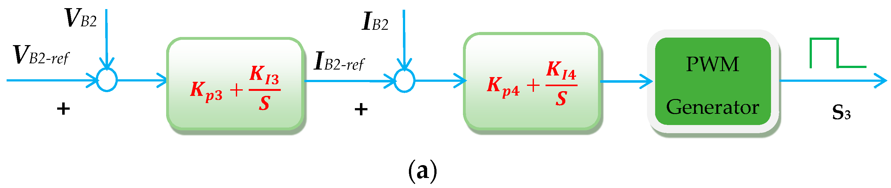
5. Control System
The controllers of the proposed system, shown in Figure 5, are the MPPT, the EV charger, and the storage converter controller. The function of the MPPT controller is to keep absorbing the peak power from the PV panel. It outputs the suitable duty ratio to the boost converter that maintains the MPPT. However, the EV converter controller regulates the charging of the EV. Finally, the battery storage converter controller is used to control the DC bus voltage and ESS charge/discharge process.
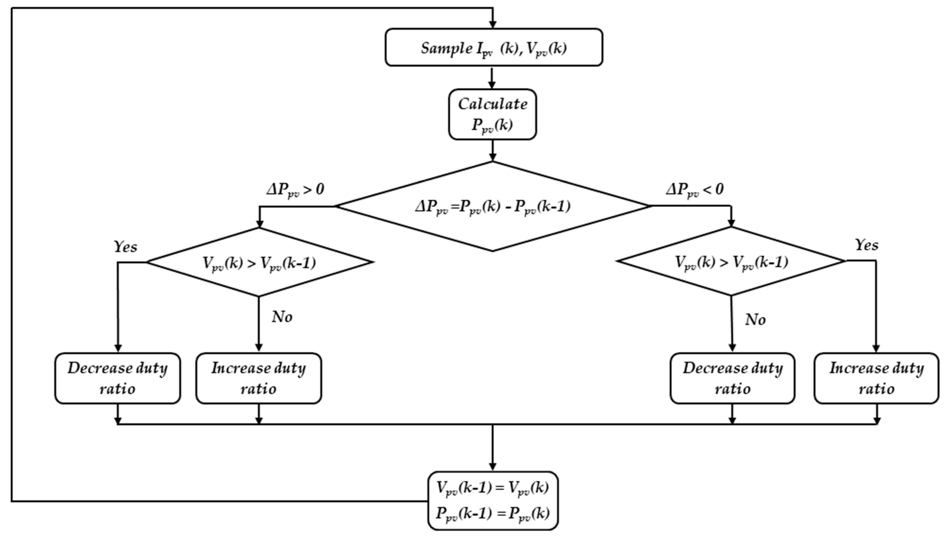
5.1. MPPT Controller
The MPPT controller is necessary to improve the PV system utilization. The algorithm of the MPPT has been implemented using many approaches [29,30,31,32]. For simplicity, the common technique called “perturb and observe” is utilized here. In this technique, a perturb of the boost converter duty ratio is made and the PV voltage and current are measured. After then, the power change is calculated then checked according to the flow chart of Figure 6 [33]. The controller is adapted to generate the necessary duty ratio for the boost converter switch to achieve MPPT conditions.
5.2. EV Converter Controller
The target of this controller is to regulate the charging process of the EV. There are various control techniques such as pulse, constant voltage (CV), constant current (CC), and constant current/constant voltage (CC/CV) techniques. Commonly, the (CC and CC/CV) techniques are preferred for their low charging time. In our system, the (CC/CV) technique is utilized. A simple PI controller is adapted for this technique. The proportion and integral gains of the PI controller are tuned using the Ziegler–Nichols method.
The experimental Ziegler–Nichols tuning algorithm can simply be summarized as the following. First, the PI controller is reduced to only the proportional part with very low proportional gain. Hence, remove the integral actions from the controller by setting it to zero. The proportional gain is then increased until continuous oscillations in the output signal are observed. Note that, when the oscillations occur, the controller should not be hitting limits. After each gain increase, you may need to make a disturbance b changing the setpoint to see if the loop oscillates. The oscillations occur at a critical proportional gain (Kpc) with an oscillation period (Tosc). By measuring the parameters Kpc and Tosc, the proportional and integral gains (Kp, Ki) for the PI controller are adjusted as:
Kp = 0.35 Kpc
Ki = 0.8 Kp / Tosc
5.3. Battery Storage Converter Controller
The objective of this controller is to regulate the DC bus voltage at a constant reference value. Consequently, charging and discharging the storage battery are adapted to serve this function. In addition, the PI controller is adapted for this converter. In case that the batteries are fully charged, the converter stops charging except for a small trickle current.
6. The Proposed System Design Calculations
According to the previous analysis, the system parameters can be calculated. Assume that the proposed system data and parameters are listed in Table 1. The design calculations are carried out as follows:
- Design calculations for ESS
As the available PV panel is 120 W, the EV power can be determined from Equation (6). Hence, using Equation (15) the ESS energy can be calculated. The charge capacity of the ESS is 39 Ah. However, the nearest available standard is 65 Ah. Normally, the range of the SOC of the ESS is from 20% to 95% [34].
- Design calculations for EV converter filter
Let that = 0.3 A, , and = 0.02. Hence, substituting in Equation (19), gives the range of inductance as 325 µH and 9375 µH. The standard inductance value of 560 µH is chosen. Then, substituting in Equation (21), gives C ≥ 363 µF. The standard inductance value of 1000 µF is chosen.
- Design calculations for Storage battery converter filter
Let that = 1.3 A and applying the same procedure to the converter of storage battery giving the range of inductance as 74 µH and 1329 µH. The standard inductance value of 560 µH is chosen. Then, substituting in Equation (21), gives C ≥ 446 µF. The standard inductance value of 1000 µF is chosen.
7. Simulation and Experimental Results
The proposed system, shown in Figure 1, is simulated and implemented physically to verify the paper idea. The parameters in Table 1 are used for both the simulation and the experimental setup. The PV panel is the Copex module of model P120. It is a polycrystalline type and has the specifications listed below. The EV battery is formed by four Li-ion batteries connected in series. Its nominal voltage is 14.8 V, the fully charged voltage is 17 V and its cut-off voltage is 12 V. The results are discussed in the following paragraphs.
7.1. Simulation Results
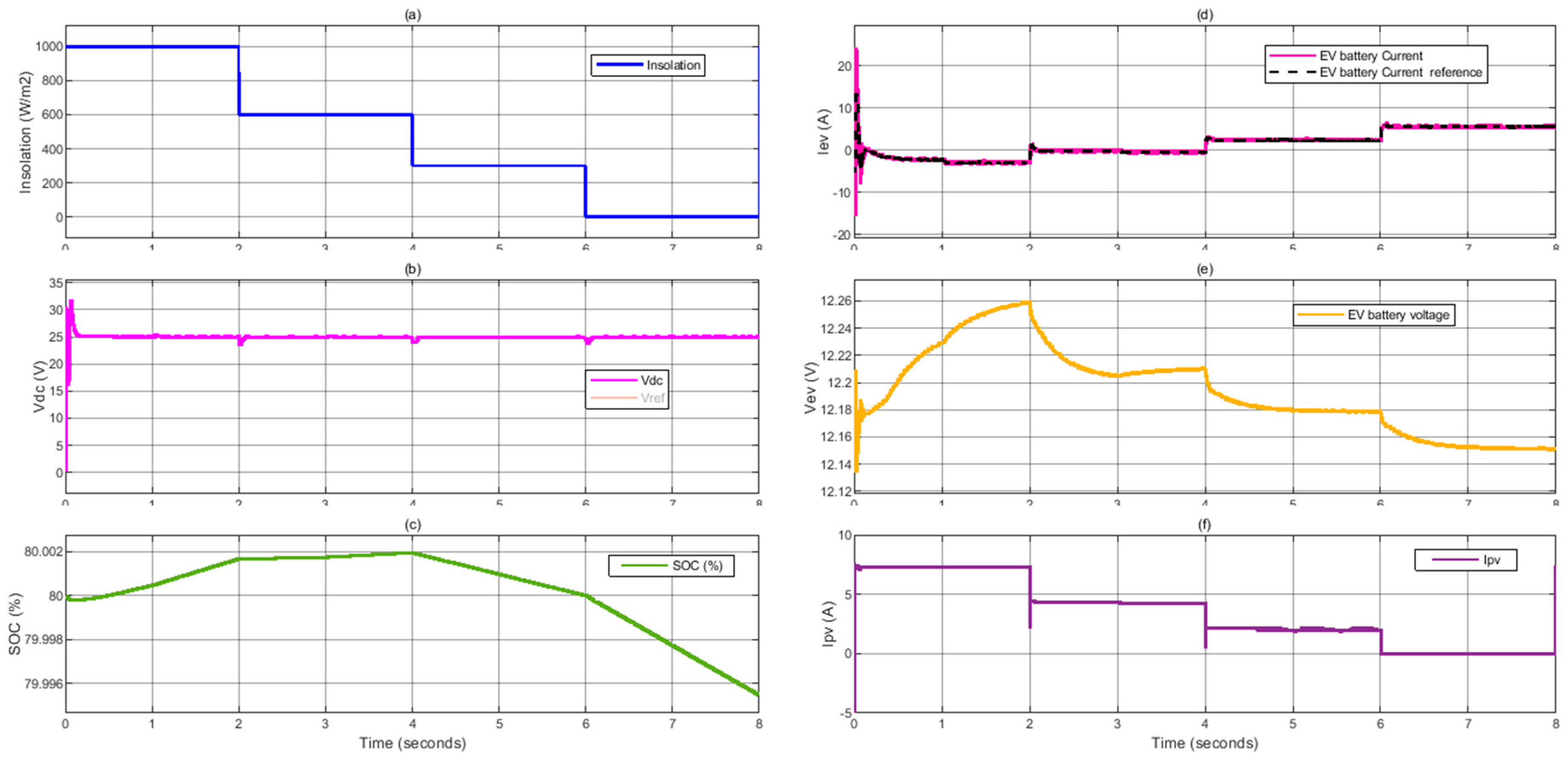
The proposed system is simulated using Matlab/Simulink platform. The system performances according to step changes in the solar irradiation of the PV panel are shown in Figure 7 and Figure 8. Figure 7a shows the irradiation level of solar energy. The DC bus voltage tracks well the reference voltage (25 V), as shown in Figure 7b. The state of charge of the lead-acid battery bank B2 is shown in Figure 7c. At the first four seconds, the insolation is ≥60%. Therefore, the generated PV power is enough to charge the EV battery and store the reserve in the B2. However, the insolation at the remaining period is ≤60% which is not enough to supply the energy to the EV. Hence, the storage battery discharges to compensate for the drop in solar energy. The current of the battery tracks its reference value generated by the DC bus voltage controller, as shown in Figure 7d. In addition, the charging and discharging processes track and compensate for the irradiation level. Figure 7e shows the voltage of the B2 battery. Its voltage increases with charging and decreases with discharging. The PV current is shown in Figure 7f. The current level is the same as the MPPT conditions.
Figure 8a shows the irradiation level of solar energy. The EV current tracks well the reference current generated by the charge controller, as shown in Figure 8b. Figure 8c shows the voltage of the B1 battery. It is continuously charging. The state of charge of the EV battery is shown in Figure 8d. Figure 8e,f show the PV power, the power of the B2 battery, and the EV battery power. At the first four seconds, the irradiation is ≥60%. Therefore, the generated PV power is enough to charge the EV battery and store the reserve in the B2. However, the insolation at the remaining period is ≤60% which is not enough to supply the energy to the EV. Hence, the storage battery discharges to compensate for the drop in solar energy. In addition, the charging and discharging processes track and compensate for the irradiation level. Its voltage increases with charging and decreases with discharging. The EV power is constant at all conditions, shown in Figure 8f.
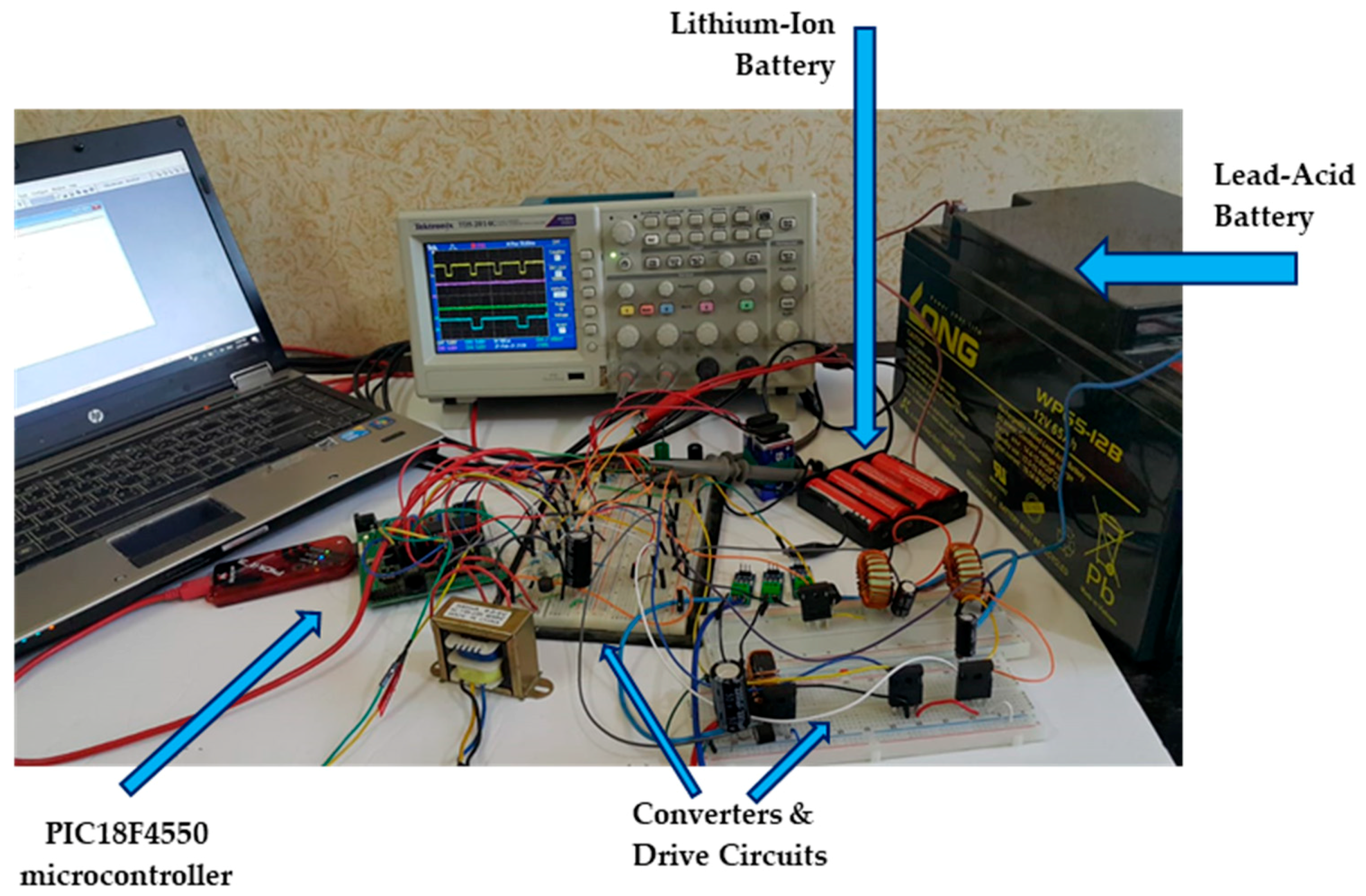
7.2. Experimental Results
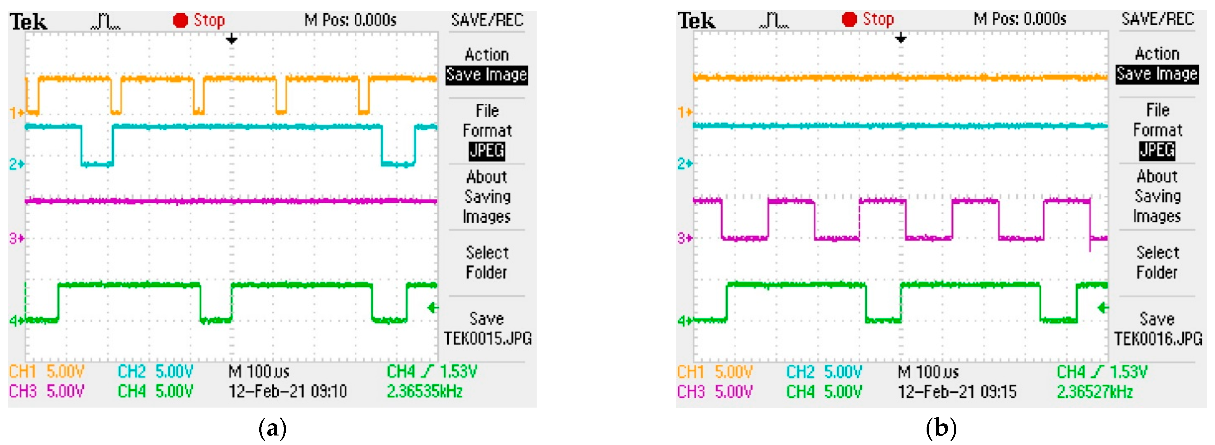
An experimental prototype is built, as shown in Figure 9, to verify the simulation results of the proposed system. The prototype has the same parameters listed in Table 1. A single-chip PIC18F4550 microcontroller, with a 16 MHz oscillator, is utilized to achieve simultaneously five controllers. The five controllers utilize three timers of the microcontroller (T0, T1, and T2) and the PWM module of the microcontroller. The microcontroller generates the control signals for the switches S1, S2, S3, and S4. The switching frequency is suitable for the converters and gives very good results. All the controllers are included in a single chip microcontroller and all control signals are generated from this microcontroller. Therefore, the execution time of different sections in the codes forces the switching frequency to be not so high. A drive circuit for each control signal is used to raise its level voltage to a suitable level. However, the drive circuits invert the generated control signals, and this inversion is considered in the written code of all controllers. The five controllers are described as follows:
- The boost converter controller
A perturb and observe maximum power point tracker is applied to achieve maximum power extraction of the PV panel. The microcontroller receives the PV voltage and current, performs the perturb-observe algorithm, then generates the control signal to the boost converter switch. This controller uses T2 and CCP modules are operating in the PWM mode.
- The DC bus voltage controller
The voltage of the DC bus is maintained constant during charging both batteries in the sunshine day hours and during night hours (discharging lead-acid battery). The controller gives the required lead-acid current in both modes of operation of the lead-acid battery considering the maximum charging current and maximum discharging current of the lead-acid battery.
- The lead-acid battery voltage controller
During the constant voltage stage of charging the lead-acid battery, its voltage is maintained at a slight value below the gassing voltage of the battery (14.4 V). During discharging mode of the battery, its voltage starts to decrease. The battery voltage is monitored so that the cut-off voltage should not be reached. This controller utilizes the reference battery voltage which is generated by the previous controller and generates the control signals to S1 and S2. This controller employs T1 and the interrupt module to achieve its target.
- The lithium-ion voltage and current controllers
The lithium-ion battery pack is charged using the constant current—constant voltage charging method. The maximum allowable charging voltage and current of the lithium-ion battery pack are controlled using the two controllers. The outer loop (voltage controller) controls the battery voltage and generates the suitable battery current taking into consideration the maximum charging current (6.5 A). The inner loop (current controller) generates the control signal to S3. This controller employs T0 and the interrupt module to realize its target.
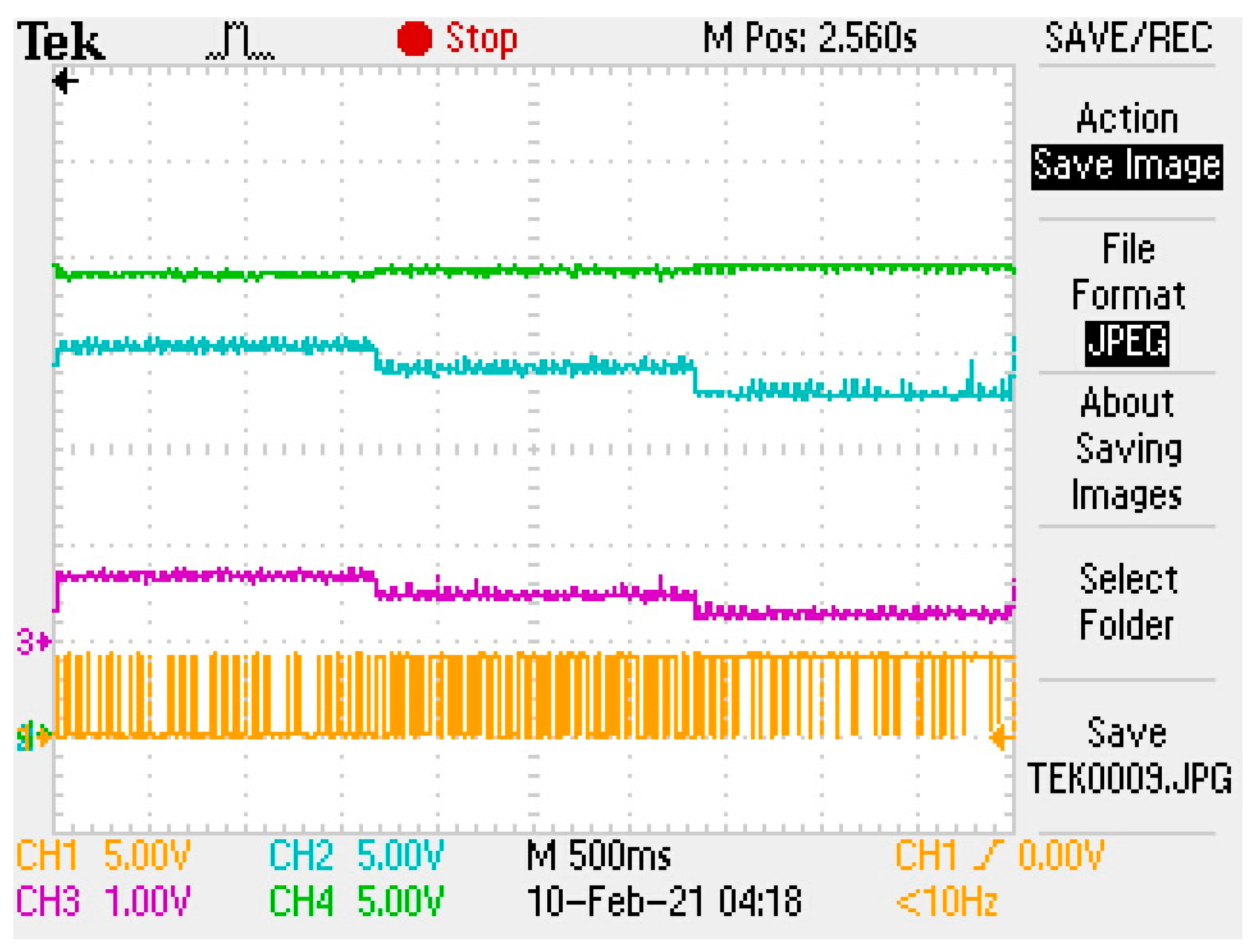
The step response of the charge controller of the lithium-ion battery is illustrated in Figure 10. The reference current is stepped at values of 3 A, 2 A, and 1 A. The voltage controller of the battery at the same time keeps the battery voltage at the suitable level corresponding to each current level. The corresponding control signal to S3 is shown. It is noticed that the duty cycle of S3 decreases as the reference current decreases. On the other side, the DC bus voltage is maintained constant.
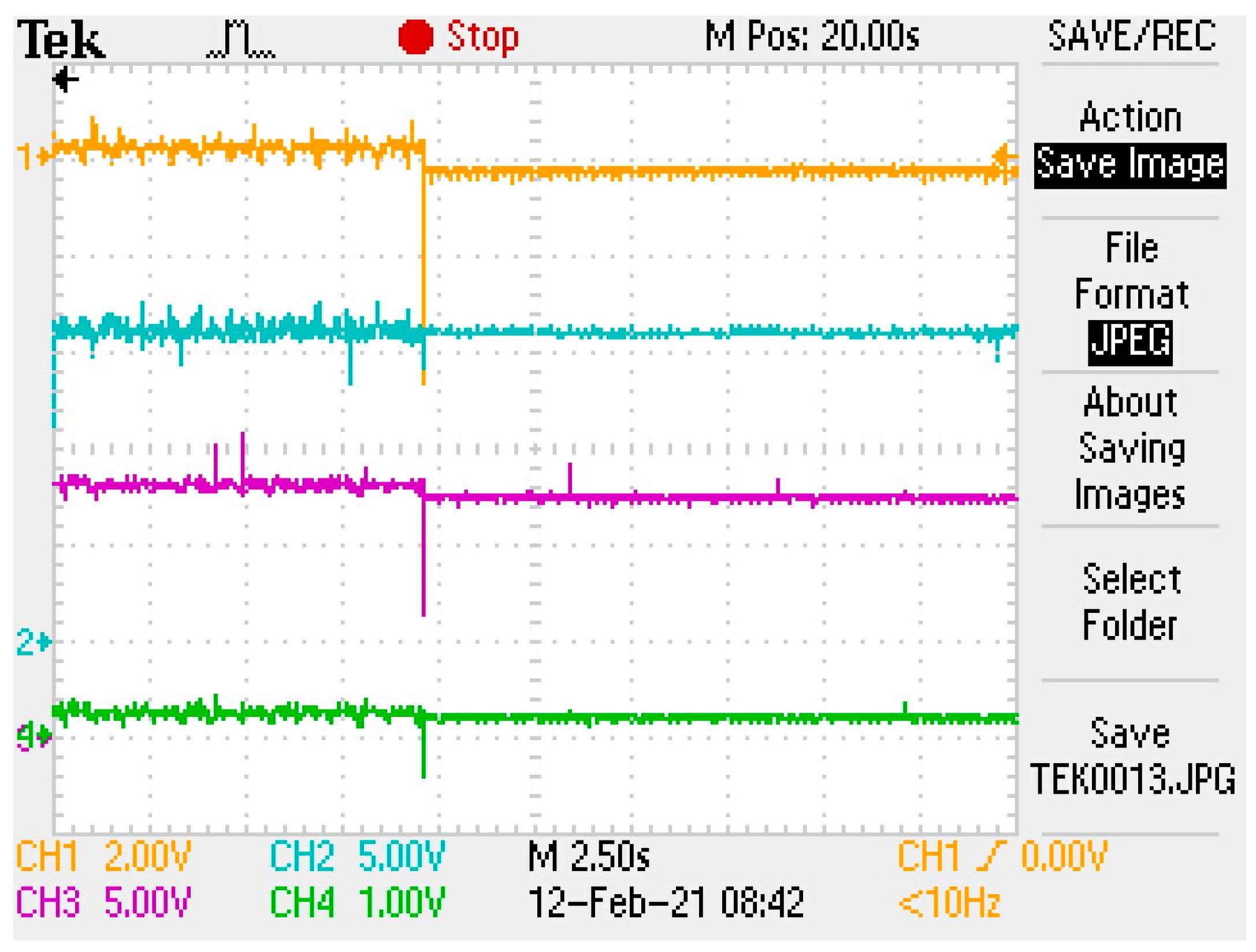
Figure 11 shows the effects of disconnecting the PV panel. The figure presents DC bus voltage, lead-acid battery voltage, lithium-ion battery voltage, and current. The lead-acid battery current changes its direction at the instant of disconnection. The controller keeps the DC bus voltage constant after the instant of disconnecting the PV panel where the lead-acid battery operates in the boost mode in which it starts discharging and its voltage slightly decreases. The charge controller of the lithium-ion battery keeps its level voltage and current at the same values before disconnecting the PV panels.
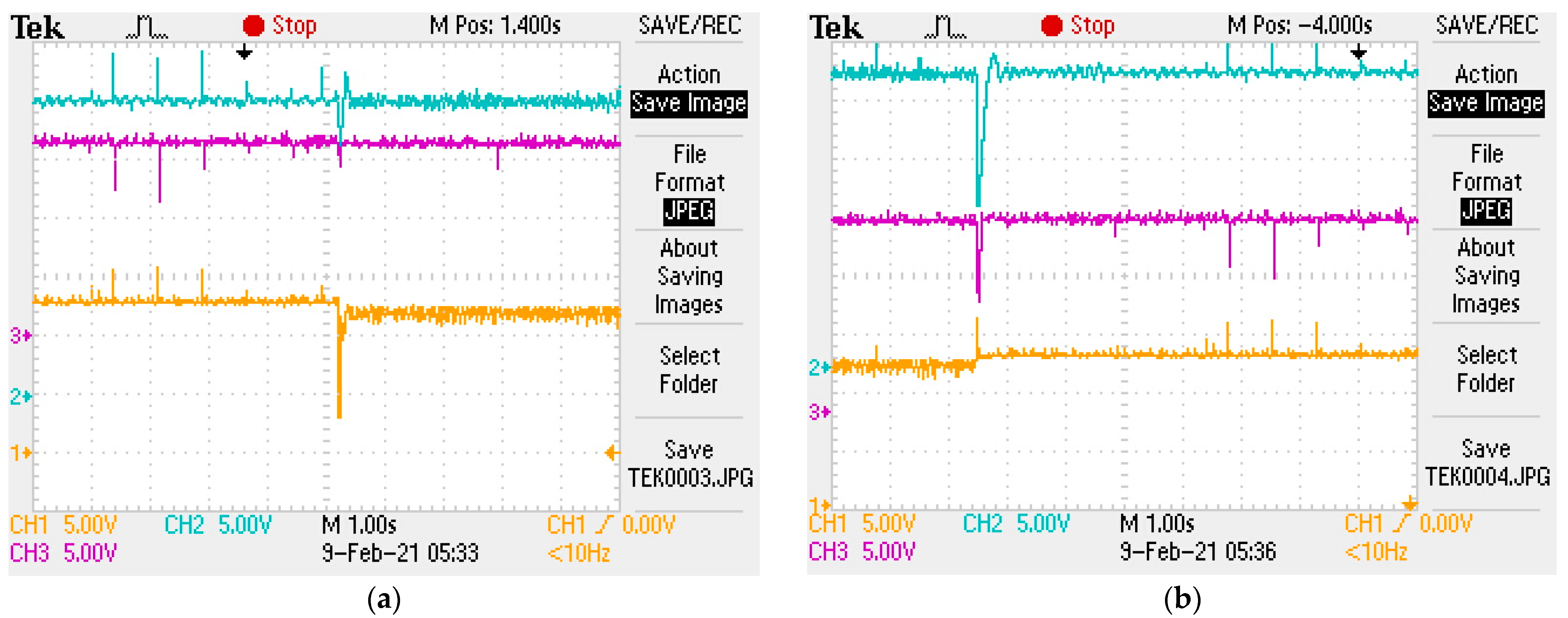
Disconnecting and reconnecting the PV panel is illustrated in Figure 12a,b. The figures give the DC bus voltage, lead-acid battery, and lithium-ion battery voltage. In Figure 12a, the PV panel is disconnected and the lead-acid battery lonely charges the lithium-ion battery. The DC bus voltage and lithium-ion battery voltage are kept at the original levels while the slightly decreases. Figure 12b shows the reconnection of the PV panel in which the two batteries are being charged and the lead-acid battery voltage slightly increases.
8. Conclusions
An isolated EV charging station based on a PV energy source is proposed. The system consists of PV panel, boost converter, ESS batteries, two DC/DC charging converters, and an EV battery. The control system consists of three controllers named the MPPT, the EV charger, and the storage converter controller. PI voltage and current controllers are adapted to control charging/discharging of the ESS system and the EV charger as well. The system is simulated and implemented physically. A single-chip PIC18F4550 microcontroller is utilized to realize the system controllers. New simple energy and power analyses procedure has been introduced. Hence, closed-form equations have been derived to help in the design phase. Complete design of the system, including the ESS size, the PV rating, and the filter components, has been proposed. Simulation and experimental results are very close and verify the effectiveness of the proposed system. At different insolation levels, the results show that the charging process of the EV battery is steady without any disturbance. However, the charging/discharging of the ESS battery responds perfectly to store and compensate for PV energy variations. The current and voltage controllers of the converters give good responses and track their references well. In addition, the MPPT controller tracks the peak conditions of the PV precisely.
Author Contributions
I.E.A. collected the funding and resources, E.H. helped in validation and visualization, and S.A.Z. conceived, designed the system model, and analyzed the results. All authors have read and agreed to the published version of the manuscript.
Funding
This research was funded by the University of Tabuk, Grant Number S-1441-0172 at https://www.ut.edu.sa/web/deanship-of-scientific-research/home (accessed on 16 July 2021).
Conflicts of Interest
The authors declare no conflict of interest.
References
- Irle, R. Global EV Sales for the 1st Half of 2019. EV Volumes. 2019. Available online: http://www.ev-volumes.com/country/total-world-plug-in-vehicle-volumes/ (accessed on 20 November 2019).
- Sun, X.; Li, Z.; Wang, X.; Li, C. Technology Development of Electric Vehicles: A Review. Energies 2020, 13, 90. [Google Scholar] [CrossRef] [Green Version]
- Luc, Vehicles & Charging Tips. Fastned. 2019. Available online: https://support.fastned.nl/hc/en-gb/sections/115000180588-Cars-charging-tips- (accessed on 30 March 2019).
- Richard, L.; Petit, M. Fast charging station with a battery storage system for EV: Optimal integration into the grid. In Proceedings of the 2018 IEEE Power & Energy Society General Meeting (PESGM), Portland, OR, USA, 5–10 August 2018; pp. 1–5. [Google Scholar]
- Chakraborty, S.; Vu, H.-N.; Hasan, M.M.; Tran, D.-D.; Baghdadi, M.E.; Hegazy, O. DC-DC Converter Topologies for Electric Vehicles, Plug-in Hybrid Electric Vehicles and Fast Charging Stations: State of the Art and Future Trends. Energies 2019, 12, 1569. [Google Scholar] [CrossRef] [Green Version]
- Liu, Y.; Dong, H.; Wang, S.; Lan, M.; Zeng, M.; Zhang, S.; Yang, M.; Yin, S. An Optimization Approach Considering User Utility for the PV-Storage Charging Station Planning Process. Processes 2020, 8, 83. [Google Scholar] [CrossRef] [Green Version]
- Ahmadi, M.; Mithulananthan, N.; Sharma, R. A review on topologies for fast-charging stations for electric vehicles. In Proceedings of the 2016 IEEE International Conference on Power System Technology (POWERCON), Wollongong, Australia, 28 September–1 October 2016; pp. 1–6. [Google Scholar] [CrossRef]
- Minh, P.V.; Le Quang, S.; Pham, M.-H. Technical Economic Analysis of Photovoltaic-Powered Electric Vehicle Charging Stations under Different Solar Irradiation Conditions in Vietnam. Sustainability 2021, 13, 3528. [Google Scholar] [CrossRef]
- Rafi, M.A.H.; Bauman, J. A Comprehensive Review of DC Fast Charging Stations with Energy Storage: Architectures, Power Converters, and Analysis. IEEE Trans. Transp. Electrif. 2021, 7, 345–368. [Google Scholar] [CrossRef]
- Yilmaz, M.; Krein, P.T. Review of battery charger topologies, charging power levels, and infrastructure for plug-in electric and hybrid vehicles. IEEE Trans. Power Electron. 2013, 28, 2151–2169. [Google Scholar] [CrossRef]
- Francfort, J.; Salisbury, S.; Smart, J.; Garetson, T.; Karner, D. Considerations for Corridor and Community DC Fast Charging Complex System Design; Idaho National Lab. (INL): Idaho Falls, ID, USA, 2017. [Google Scholar]
- Nicholas, M.; Hall, D. Lessons Learned on Early Fast Electric Vehicle Charging Systems; The National Academies of Sciences, Engineering, and Medicine: Washington, DC, USA, 2018. [Google Scholar]
- Gao, Z.; Liu, X. An Overview on Fault Diagnosis, Prognosis and Resilient Control for Wind Turbine Systems. Processes 2021, 9, 300. [Google Scholar] [CrossRef]
- Polimeni, S.; Nespoli, A.; Leva, S.; Valenti, G.; Manzolini, G. Implementation of Different PV Forecast Approaches in a MultiGood MicroGrid: Modeling and Experimental Results. Processes 2021, 9, 323. [Google Scholar] [CrossRef]
- Bhatti, A.R.; Salam, Z. Charging of electric vehi-cle with constant price using photovoltaic based grid-connected system. In Proceedings of the 2016 IEEE International Conference on Power and Energy (PECon), Melaka, Malaysia, 28–29 November 2016; pp. 268–273. [Google Scholar] [CrossRef]
- Kumar, V.; Teja, V.R.; Singh, M.; Mishra, S. PV Based Off-Grid Charging Station for Electric Vehicle. IFAC Pap. 2019, 276–281. [Google Scholar] [CrossRef]
- Mouli, C.G.R.; Schijffelen, J.; Heuvel, M.; Kardolus, M.; Bauer, P. A 10 kW Solar-Powered Bidirectional EV Charger Compatible With Chademo and COMBO. IEEE Trans. Power Electron. 2019, 34, 1082–1098. [Google Scholar] [CrossRef] [Green Version]
- Monteiro, V.; Pinto, J.G.; Afonso, J.L. Experimental Validation of a Three-Port Integrated Topology to Interface Electric Vehicles and Renewables With the Electrical Grid. IEEE Trans. Ind. Inform. 2018, 14, 2364–2374. [Google Scholar] [CrossRef] [Green Version]
- Singh, S.A.; Carli, G.; Azeez, N.A.; Williamson, S.S. Modeling, Design, Control, and Implementation of a Modified Z-Source Integrated PV/Grid/EV DC Charger/Inverter. IEEE Trans. Ind. Electron. 2018, 65, 5213–5220. [Google Scholar] [CrossRef]
- Chaudhari, K.; Ukil, A.; Kumar, K.N.; Manandhar, U.; Kollimalla, S.K. Hybrid Optimization for Economic Deployment of ESS in PV-Integrated EV Charging Stations. IEEE Trans. Ind. Inform. 2018, 14, 106–116. [Google Scholar] [CrossRef]
- Zhang, Y.P.; You and Cai, L. Optimal Charging Scheduling by Pricing for EV Charging Station With Dual Charging Modes. IEEE Trans. Intell. Transp. Syst. 2019, 20, 3386–3396. [Google Scholar] [CrossRef]
- Hernandez, J.C.; Sutil, F.S. Electric vehicle charg-ing stations feeded by renewable: Pv and train regen-erative braking. IEEE Lat. Am. Trans. 2016, 14, 3262–3269. [Google Scholar] [CrossRef]
- Ibrahim, H.; Sayed, K.; Kassem, A.; Mostafa, R. A new power management strategy for battery electric vehicles. IET Electr. Syst. Transp. 2018, 9, 65–74. [Google Scholar]
- Savio, D.A.; Juliet, V.A.; Chokkalingam, B.; Padmanaban, S.; Holm-Nielsen, J.B.; Blaabjerg, F. Photovoltaic Integrated Hybrid Microgrid Structured Electric Vehicle Charging Station and Its Energy Management Approach. Energies 2019, 12, 168. [Google Scholar] [CrossRef] [Green Version]
- Ashish Kumar Karmaker, M.; Alamgir, H.; Nallapaneni, M.K.; Vishnupriyan, J.; Arunkumar, J.; Biplob, R. Analysis of Using Biogas Resources for Electric Vehicle Charging in Bangladesh: A Techno-Economic-Environmental Perspective. Sustainability 2020, 12, 2579. [Google Scholar] [CrossRef] [Green Version]
- Bai, S.; Yu, D.; Lukic, S. Optimum design of an EV/PHEV charging station with DC bus and storage system. In Proceedings of the 2010 IEEE Energy Conversion Congress and Exposition, Atlanta, GA, USA, 12–16 September 2010; pp. 1178–1184. [Google Scholar] [CrossRef] [Green Version]
- Rashid, M. Power Electronics Handbook, 2nd ed.; Elsevier Press: Amsterdam, The Netherlands, 2011. [Google Scholar]
- Arancibia, A.; Strunz, K. Modeling of an electric vehicle charging station for fast DC charging. In Proceedings of the 2012 IEEE International Electric Vehicle Conference, Greenville, SC, USA, 4–8 March 2012; pp. 1–6. [Google Scholar] [CrossRef]
- Elbalawi, H.; Zaid, S.A. H5 Transformerless Inverter for Grid Connected PV System with Improved Utilization Factor and Simple Maximum Power Point Algorithm. Energies 2018, 11, 2912. [Google Scholar] [CrossRef] [Green Version]
- Husain, M.A.; Tariq, A.; Hameed, S.; Arif, M.S.B.; Jain, A. Comparative assessment of maximum power point tracking procedures for photovoltaic systems. Green Energy Environ. 2017, 2, 5–17. [Google Scholar] [CrossRef]
- Zaid, S.A.; Kassem, A.M. Review, analysis and improving the utilization factor of a PV-grid connected system via HERIC transformerless approach. Renew. Sustain. Energy Rev. 2017, 73, 1061–1069. [Google Scholar] [CrossRef]
- Albalawi, H.; Zaid, S.A. Performance Improvement of a Grid-Tied Neutral-Point-Clamped 3-φ Transformerless Inverter Using Model Predictive Control. Processes 2019, 7, 856. [Google Scholar] [CrossRef] [Green Version]
- Sera, D.; Mathe, L.; Kerekes, T.; Spataru, S.V.; Teodorescu, R. On the Perturb-and-Observe and Incremental Conductance MPPT Methods for PV Systems. IEEE J. Photovolt. 2013, 3, 1070–1078. [Google Scholar] [CrossRef]
- Biya, T.S.; Sindhu, M.R. Design and Power Management of Solar Powered Electric Vehicle Charging Station with Energy Storage System. In Proceedings of the 2019 3rd International Conference on Electronics, Communication and Aerospace Technology (ICECA), Coimbatore, India, 12–14 June 2019; pp. 815–820. [Google Scholar] [CrossRef]
Figure 1.
The proposed PV-powered EVCS with the battery storage system.

Figure 2.
The PV array power distribution for one day.

Figure 3.
The system power flow diagram.

Figure 4.
The system converters circuit diagram: (a) bidirectional converter, (b) buck converter.

Figure 5.
The proposed system controllers: (a) MPPT controller, (b) EV charge controller, and (c) storage battery converter controller.
Figure 5.
The proposed system controllers: (a) MPPT controller, (b) EV charge controller, and (c) storage battery converter controller.


Figure 6.
Perturb and Observe MPPT algorithm flowchart.

Figure 7.
(a) PV irradiation level, (b) DC bus voltage, (c) state of charge of the lead-acid battery bank, (d) the lead-acid battery current and reference current, (e) the lead-acid battery voltage (f) the PV current.
Figure 7.
(a) PV irradiation level, (b) DC bus voltage, (c) state of charge of the lead-acid battery bank, (d) the lead-acid battery current and reference current, (e) the lead-acid battery voltage (f) the PV current.

Figure 8.
(a) PV irradiation level, (b) the EV battery bank current and reference current, (c) the EV battery voltage, (d) state of charge of the EV battery, (e) the PV and lead-acid battery power (f) the EV charging power.
Figure 8.
(a) PV irradiation level, (b) the EV battery bank current and reference current, (c) the EV battery voltage, (d) state of charge of the EV battery, (e) the PV and lead-acid battery power (f) the EV charging power.

Figure 9.
The experimental setup.

Figure 10.
The experimental response of the EV controller: Ch1: Control signal of S3 (5 V/div) Ch2: Li-ion battery voltage (5 V/div.) Ch3: Li-ion battery current (4 A/div), Ch4: DC bus voltage (5 V/div).
Figure 10.
The experimental response of the EV controller: Ch1: Control signal of S3 (5 V/div) Ch2: Li-ion battery voltage (5 V/div.) Ch3: Li-ion battery current (4 A/div), Ch4: DC bus voltage (5 V/div).

Figure 11.
The system response upon disconnecting the PV: Ch1: lead acid battery current (6 A/div) Ch2: Li-ion battery voltage (5 V/div) Ch3: lead acid battery voltage (5 V/div), Ch4: Li-ion battery current (4 A/div).
Figure 11.
The system response upon disconnecting the PV: Ch1: lead acid battery current (6 A/div) Ch2: Li-ion battery voltage (5 V/div) Ch3: lead acid battery voltage (5 V/div), Ch4: Li-ion battery current (4 A/div).

Figure 12.
The system response upon: (a) connecting and (b) disconnecting the PV. Ch1: lead–acid battery voltage (5 V/div) Ch2: DC bus voltage (5 V/div) Ch3: Li-ion battery voltage (5 V/div).
Figure 12.
The system response upon: (a) connecting and (b) disconnecting the PV. Ch1: lead–acid battery voltage (5 V/div) Ch2: DC bus voltage (5 V/div) Ch3: Li-ion battery voltage (5 V/div).

Figure 13.
Control signals from the microcontroller for the switches: (a) PV panel is connected, and the two batteries are being charged, (b) PV panel is disconnected. S4 (CH1)—S1 (CH2)—S2 (CH3)—S3 (CH4).
Figure 13.
Control signals from the microcontroller for the switches: (a) PV panel is connected, and the two batteries are being charged, (b) PV panel is disconnected. S4 (CH1)—S1 (CH2)—S2 (CH3)—S3 (CH4).


Table 1.
System Parameters.
| Item | Parameter | Value |
|---|---|---|
| PV | SC current Isc | 8.82 A |
| OC voltage Voc | 19.2 V | |
| MPPT power PMPPT | 7.5 × 16 W | |
| ESS Battery | Type | Lead Acid |
| Rating | 65 Ah, 12 V | |
| Max. charging current | 13 A | |
| EV Battery | Type | Lithium-ion |
| Rating | 6.5 Ah, 3.7 V | |
| Max. charging current | 3 A | |
| Max. discharging current | 5 A | |
| L | 560 µH | |
| C | 1000 µF | |
| Cdc | 2200 µF | |
| PWM carrier frequency | 4 kHz |
Table 2.
The experimental results summary.
| Variable | Parameter | Connecting the PV | Disconnecting the PV |
|---|---|---|---|
| DC bus Voltage | Overshoot (%) | 20 | 40 |
| Setling time (s) | 0.2 | 0.5 | |
| ESS Battery Voltage | Overshoot (%) | 67 | 0 |
| Setling time (s) | 0.2 | 0 | |
| EV Battery Voltage | Overshoot (%) | 0 | 40 |
| Setling time (s) | 0 | 0.1 |
Publisher’s Note: MDPI stays neutral with regard to jurisdictional claims in published maps and institutional affiliations. |
© 2021 by the authors. Licensee MDPI, Basel, Switzerland. This article is an open access article distributed under the terms and conditions of the Creative Commons Attribution (CC BY) license (https://creativecommons.org/licenses/by/4.0/).
Share and Cite
MDPI and ACS Style
Atawi, I.E.; Hendawi, E.; Zaid, S.A. Analysis and Design of a Standalone Electric Vehicle Charging Station Supplied by Photovoltaic Energy. Processes 2021, 9, 1246. https://doi.org/10.3390/pr9071246
AMA Style
Atawi IE, Hendawi E, Zaid SA. Analysis and Design of a Standalone Electric Vehicle Charging Station Supplied by Photovoltaic Energy. Processes. 2021; 9(7):1246. https://doi.org/10.3390/pr9071246
Chicago/Turabian StyleAtawi, Ibrahem E., Essam Hendawi, and Sherif A. Zaid. 2021. "Analysis and Design of a Standalone Electric Vehicle Charging Station Supplied by Photovoltaic Energy" Processes 9, no. 7: 1246. https://doi.org/10.3390/pr9071246
Note that from the first issue of 2016, this journal uses article numbers instead of page numbers. See further details here.