Experimental Evaluation of Miniature Impedance Board for Loosening Monitoring of the Threaded Pipe Connection
 Yabin Liang
 Yixuan Chen
 Zuocai Zhang
 Qian Feng
- 1Institute of Seismology, CEA, Wuhan, China
- 2Hubei Key Laboratory of Earthquake Early Warning, Wuhan, China
- 3Hubei Earthquake Administration, Wuhan, China
- 4Wuhan Institute of Earthquake Engineering Co. Ltd., Wuhan, China
Electromechanical impedance (Electromechanical impedance)-based methods as potential nondestructive evaluation (NDT) techniques have been widely used in the field of structural health monitoring (SHM), especially for the civil, mechanical, and aerospace engineering fields. However, it is still difficult to apply in practical applications due to the limitations of the impedance measurement hardware, which is usually expensive, bulky, and heavy. In this paper, a small, lightweight, and low power consumption EMI-based structural health monitoring system combined with the low-cost miniature impedance board AD5933 was studied experimentally to investigate its quantifiable performance in impedance measurement and structural damage identification. At first, a simple impedance test with a free PZT patch was introduced to present the impedance calibration and measurement procedure of AD5933, and then its calibration performance was validated by comparing the signature with the one measured by a professional impedance analyzer (WK6500B). In order to further validate the feasibility and effectiveness of the AD5933 board in practical applications, a threaded pipe connection specimen was assembled in the laboratory and then connected with the AD5933 to acquire its impedance signatures under different loosening severities. The final results demonstrated that the impedance measured by the AD5933 show a good consistency with the measurements by the WK6500B, and the evaluation board could be successfully utilized for the loosening severities identification and quantitatively evaluation.
Introduction
Electromechanical impedance (EMI)-based structural health monitoring as a NDT technique was first proposed by [1]; and exhibits great potential in the field of structural health monitoring [2–4]. In recent years, the EMI technique had been employed by researchers to assess structures in various fields and of various materials: aerospace and aircraft structures [5], concrete structures [6–8], steel structures [9–11], jacket-type offshore structures [12], and polymer and reinforced composite structures [13]. The basic principle of the EMI-based damage detection technique is to track the electrical impedance of a PZT (lead zirconate titanate) transducer, which was surface bonded onto the host structure. Owing to the interactive electromechanical coupling properties of the PZT transducer, slight changes in the physical characteristics of the host structure can be captured by detecting the changes in the electrical impedance of the PZT transducer. Thus, the health condition and service status of the host structure can be effectively evaluated by measuring the electrical impedance of the PZT transducer and comparing it with baseline data.
Though EMI-based techniques have received great attention in the area of structural health monitoring and damage identification, they still face many challenges during practical application. One of the biggest challenges is the nature of impedance measurement hardware, which is usually very expensive, bulky, and heavy, such as the professional precious impedance analyzer (WK6500B, Wayne Kerr Electronics Co., United Kingdom) with a price of approximately 10,000 USD, a mass of approximately 14 kg, and the dimensions 190 mm × 440 mm × 525 mm. With these disadvantages, it becomes very difficult for EMI-based techniques to be applied in field use for online SHM, and therefore seriously limits its wider adoption in the future.
In recent years, an AD5933 evaluation board manufactured by Analog Devices Co. (Norwood, MA, United States) has received a lot of attention in the field of SHM due to its excellent impedance measurement ability. The board is very cheap (approximately 60 USD), and is characterized by its low weight (approximately 240 g) and small dimensions (80 mm × 80 mm). The evaluation board can measure the impedance signatures up to 100 kHz with 512 maximum data points. Due to these distinguishing advantages, much research had been published around this low-cost, on-board SHM system [14–19]. For example [20], investigated the influence of the calibration process of the AD5933 on impedance measurements and validated its damage detection ability in carbon fiber reinforced polymer CFRP panels suffering delamination [21]. Successfully applied the AD5933 board to detect common defects of the glass fiber composite plates, such as delamination and cracking. All the published research showed that impedance measurement by the AD5933 board provides good consistency with measurements obtained from a professional impedance analyzer. Therefore, some researchers have demonstrated that a mini-impedance measuring board such as the AD5933 is likely to be a key part of future sensor systems, especially in the next generation of EMI-based SHM systems.
On the other hand, threaded connections have been widely utilized in pipeline engineering due to their distinguishing advantages of flexibility (aiding in assembly and disassembly), excellent bearing capacity for large axial force, good interchangeability, and reusability [22, 23]. However, in practical application this type of connection is always subjected to variable external loads and environmental pollution, which may induce cracks or loosen the connection during its service period. In this situation, it becomes necessary to guarantee a sealed and secure connection and thus reduce potential leakage risk. With the development of SHM techniques [24–26], many novel methods have been proposed by researchers in recent years to deal with this issue. For example, a distributed temperature sensing system (DTS), combined with optical fibers, has been successfully employed to detect and locate leakage along the pipelines by monitoring variations in the surrounding temperature of the pipe [27, 28]. In addition, the piezoceramic-based active sensing method combined with the time reversal technique has also been utilized to identify when the connection becomes loose and evaluate the severity of the looseness [29]. In 2018 [30], tried to apply an EMI-based technique to monitor the health condition of threaded pipe connections in real time, but the impedance signatures in this research were acquired by a professional impedance analyzer.
In this paper, the miniature impedance board AD5933 was employed as an EMI-based SHM system, and its performance in impedance measurement and damage detection was experimentally investigated. Firstly, a free PZT impedance test was carried out to present in detail the impedance calibration and measurement procedure of the AD5933, and its impedance calibration performance was also investigated by comparing the results with a professional impedance analyzer (WK6500B). Then, a threaded pipe connection was assembled in the laboratory as a test specimen and experimentally investigated to further validate the feasibility and effectiveness of the AD5933 board, especially in its damage identification ability under several different connection-loosening severities. During the experiments, all the impedance measurements taken by the AD5933 board were compared with the ones measured by the WK6500B.
Electromechanical Impedance Principle
In 1994 [1], first proposed the concept of electromechanical impedance-based techniques and tried to apply them in the field of structural health monitoring. EMI takes full advantage of the dual functions of the piezoelectric patches it utilizes, which can act as both the actuator and sensor simultaneously. These unique interactive electromechanical coupling properties provide the piezoelectric patches with the potential to be employed to detect the slightest alterations in frequency response functions for the host structure. In this way, structural health condition and service status can be effectively identified.
Normally, the small sized piezoelectric transducer (lead zirconate titanate-PZT) is surface bonded onto the host structure by the high-strength adhesive, and is powered by voltage or current. Thus, for the PZT–host structure coupling system, its integrated electro-mechanical characteristics may be electrically represented by the PZT electrical impedance, which is always directly affected by the dynamics of the PZT patch and the host structure. Among them, the mechanical impedance of the PZT patch, denoted by Za (
where Zs (
With the help of this formula, the electrical impedance of the PZT patch before and after a damage occurrence for the host structure can be calculated and compared, thus the health condition and service status of the host structure can be evaluated.
Miniature Impedance Board AD5933
As shown in Figure 1A, the AD5933, as a miniature electronic board developed by Analog Devices Co., has the ability to measure impedance across a limited frequency, ranging from a few Hertz up to 100 kHz. The evaluation board receives information, communication, and power vis USB cable when connected to a laptop which has been pre-installed with the supporting software provided by Analog Devices. As shown in Figure 1B, the AD5933 board includes an internal oscillator, signal generator (direct digital synthesizer, DDS), digital-to-analog converter (DAC), transmit amplifier, current-to-voltage converter, gain control block, analog-to-digital converter (ADC), discrete Fourier transform (DFT), digital signal processing engine, and I2C bus controller. The detailed technical specification for AD5933 is presented as Table 1.
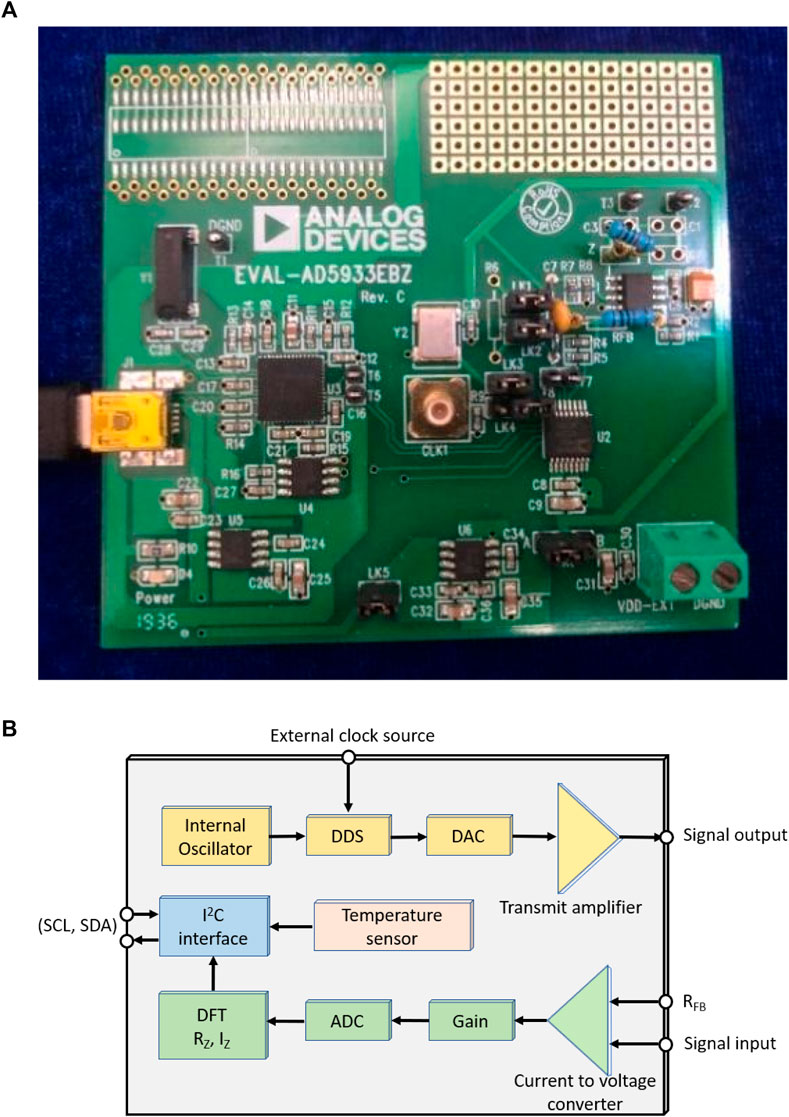
FIGURE 1. AD5933 evaluation board (A) photo (B) block diagram.
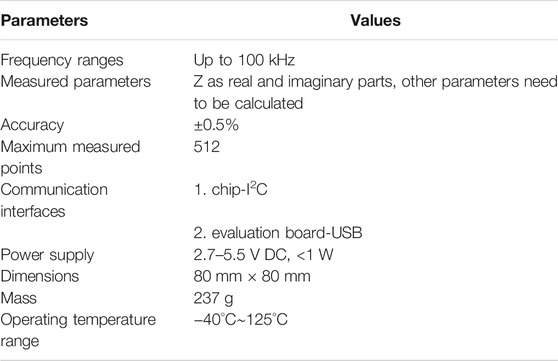
TABLE 1. Technical specification for AD5933.
For the impedance measurement, the DDS and DAC work together to generate an analog frequency sweep signal, which is then amplified and sent out as an output signal to excite the measured impedance. Then, working together with the current obtained from gain resistor RFB, the response signal in the form of electric current is converted to voltage by current-to-voltage converter, and then processed by the ADC and DFT engine after gain. In this way, the real and imaginary data of the impedance can be calculated by the DFT engine and then sent to the I2C controller, and finally transmitted to the laptop via USB cable.
It should be noted that the evaluation board also has a high performance trimmed 16 MHz surface-mount crystal that can be used as a system clock for the AD5933 when needed. Communication and interfacing to the AD5933 board is via a USB cable connected to a laptop, which controls and generates the I2C signals. With the help of the pre-installed dedicated software developed by Analog Devices, some related work can be done on the laptop, including setting working parameters (the frequency and gain etc.), reading the temperature from the internal sensor, performing calibration, and conducting and storing the measurements.
Calibration Procedure and Performance for AD5933
Calibration Procedure
For evaluation of the AD5933 board, a proper calibration before measurement is of critical importance and directly influences the accuracy of the final measurement. Calibration of the AD5933 evaluation board is required each time the software or hardware is restarted or reset. In this research, in order to present the calibration procedure in detail and investigate the calibration performance of the AD5933 board, a free PZT patch was employed to connect to the AD5933 board and conduct the calibration and impedance measurement test.
According to the documentation [31], the calibration gain factor can be calculated in two different ways, i.e., mid-point or multi-point frequency calibration. In this study, the mid-frequency point calibration method combined with a resistor with known resistance value was selected because of convenience, and the influences to the impedance measurement stemming from different calibration methods can be further studied in future works. In this situation, it should be noted that this calibration approach works correctly only for measurements related to electronic elements like resistors with purely resistance characteristics. Therefore, the detailed calibration procedure can be summarized as following:
1) Obtaining the referential measurements
First, a professional impedance analyzer was connected with the free PZT patch, and a wide frequency excitation was applied to the patch. Then, the corresponding impedance signature of the PZT patch was measured and analyzed to select the sensitive frequency band. In addition, the minimal and maximal impedance magnitude was also obtained.
2) Selection of RCAL and RFB
According to the application note report published by [32]; the value of the calibration resistor RCAL should be equal to:
where Zmin, Zmax denote the minimal and maximal impedance of the measured PZT element, respectively. Based on the pre-test results of step (1) (Zmin, Zmax), the calibration resistor RCAL was first determined, and then the referential resistor RFB was also selected as RFB = RCAL (in the pure resistance case).
3) Calibration
After the RCAL and RFB resistors were determined and then connected to the AD5933 board at the desired position, the related evaluation parameters of the board could be set by the evaluation software dashboard. After that, an impedance measurement can be conducted, and thus several related parameters can be respectively, calculated by the acquisition of the real RZ and imaginary IZ datasheet, for example, the magnitude M, the gain factor GF, and the phase
When the real and imaginary data of the impedance have been obtained by AD5933, the magnitude of the known resistance RCAL can be calculated as:
Based on the calculated magnitude M, the gain factor GF could be obtained by following the formula:
where YCAL, ZCAL refer to calibration admittance and impedance, respectively. In this study, calibrating resistor RCAL is utilized instead of impedance ZCAL.
On the other hand, the phase
4) Measurement
Measurement was taken by removing the RCAL resistor from the board and connecting it to the free PZT patch instead, then conducting an impedance measurement using the AD5933 board, and acquiring the real and imaginary data for the impedance. In this situation, the impedance magnitude of the free PZT patch can be achieved following the equation:
where MPZT is the impedance magnitude for the piezoelectric transducer calculated based on Eq. 2. At the same time, the phase
5) Calibration for the measurement
Based on the phase
6) Extraction of the real and imaginary data
Based on the corrected ZPZT in step 4) and the phase
where
Calibration Performance
In this calibration test for a free PZT patch, the sweep frequency band was selected as 10–30 kHz following the calibration procedure in step 1) of the last section, and the calibration resistor RCAL was selected as 10 k
Characteristics measured by the WK6500B and AD5933 boards with the calibration resistance 10 k
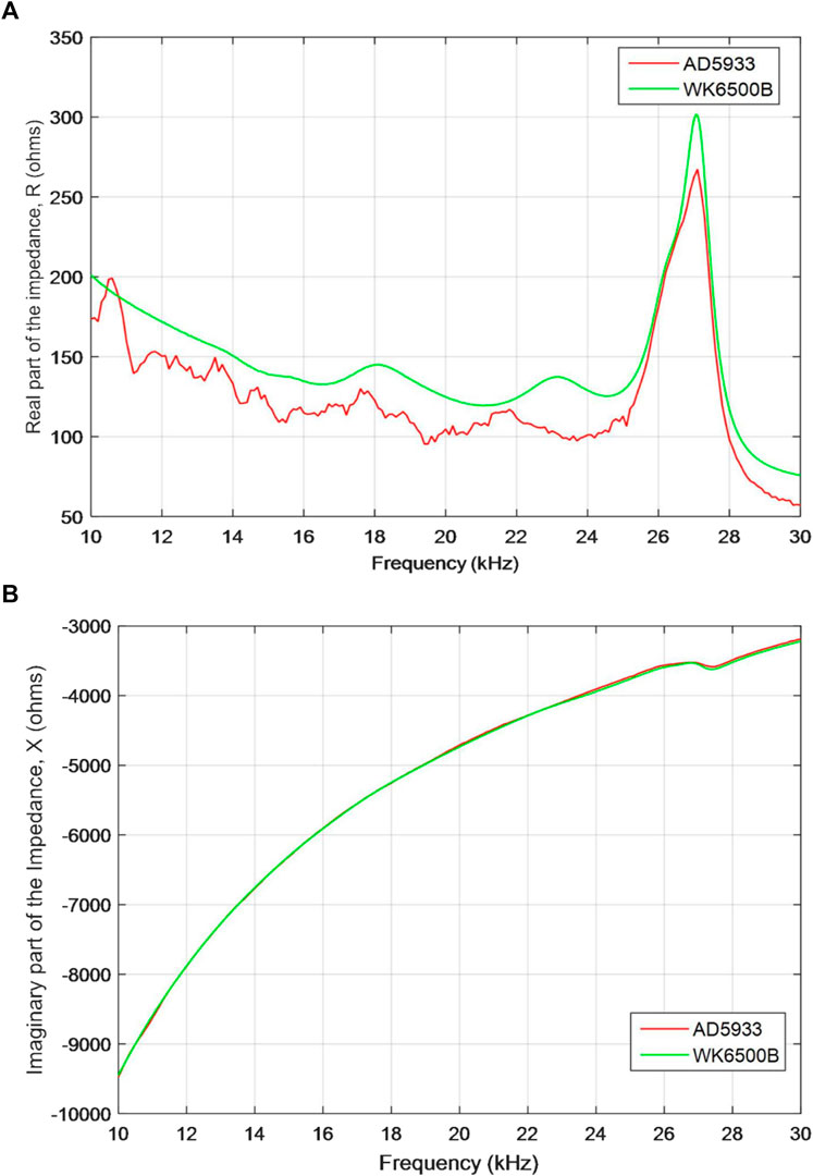
FIGURE 2. Comparison of impedance measurements for WK6500B and AD5933: (A) the real part, and (B) the imaginary part of the impedance.
Based on the results, it can be concluded that the AD5933 evaluation board has the potential to be utilized as an impedance analyzer to acquire the electromechanical impedance signal of the host structures after proper calibration.
On the other hand, it should be noted that many factors, such as the A/D conversion and the inherent electrical impedance of the internal chips, may induce the difference between the impedance signatures measured by the AD5933 and the professional impedance analyzer. In addition, the calibration process of AD5933 will also significantly influence the measurement result, for example, the selection of RCAL and RFB resistor, the selection of calibration method (mid-point frequency or multiple point frequency calibration), the number of sampling points, and the calculation of the gain factor. The temperature sensor of AD5933 requiring to measure and compensate for temperature also contributes to the differences. However, it does not seem to cause significant problems for SHM, because the impedance-based SHM is based on the relative difference between two normalized signals: the healthy condition and the test conditions [15, 33].
Experimental Preparations
In the above section, the detail calibration procedures of AD5933 have been discussed, its impedance measurement performance after calibration had also been verified by a free PZT transducer, and finally a good, consistent result was observed. In this section, in order to further validate the impedance measurement performance of the AD5933 evaluation board, especially in practical application, a threaded pipe connection was assembled in the laboratory and then the board experimentally investigated for its damage detection ability.
Experimental Setup
As shown in Figure 3, a pipeline connection specimen was assembled in the laboratory from two pipe segments and a threaded coupling part, and then fixed to the ground by a steel fixture. A PZT-5H patch was bonded onto the surface of the threaded connection by epoxy adhesive. Table 2 presents the detailed geometric and material parameters of the specimen and the PZT patch.
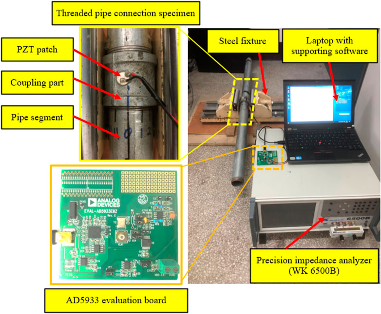
FIGURE 3. Experimental setup.
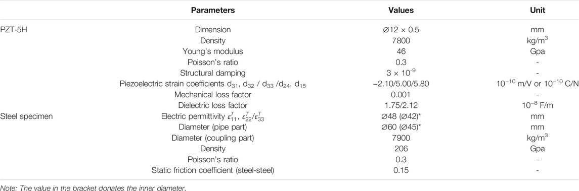
TABLE 2. The parameters of the specimen and the PZT patch.
The complete experimental setup consists of the pipeline test specimen, the AD5933 evaluation board, and a laptop, as shown in Figure 3. The surface mounted PZT patch in the specimen was connected with the AD5933 board via a USB cable. The corresponding software provided by Analog Devices Co. was pre-installed on the laptop to pre-set the acquisition parameters and control the board for the impedance measurement during the test. In addition, a professional impedance analyzer, WK6500B, was employed here for result comparison.
Experimental Procedure
In the experiment, in order to quantitatively indicate the changes in the contact area of the threaded connection during the process of loosening occurring and developing, the relative rotation circles between the coupling and the pipe segment were introduced as a monitoring variable. Therefore, seven different looseness severities were established and investigated, from tightest to loosest for the contact region of the pipe connection, by rotation of the pipe segment. At the beginning of the experiment, the initial tightest status was regarded as the health baseline for the connection. Then, six loosening severities were introduced by rotating the pipe segment from one circle to six circles with the step-increase of one circle for each level of severity. Figure 4 presents the four different loosening severities of the threaded pipe connection during the experiment. Thus, a total of seven service statuses for the threaded pipe connection were implemented and investigated in this study.
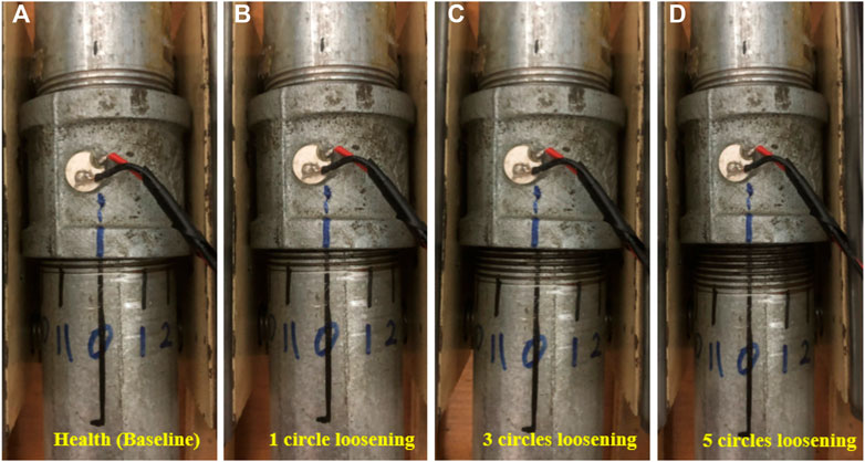
FIGURE 4. Several loosening severities for (A) health (baseline), (B) one circle, (C) three circles and (D) five circles of loosening.
Calibration and Acquisition Procedure
In the experiment, the AD5933 evaluation board was utilized to acquire the impedance data of the test specimen under different loosening severities. As per the above description in section four, the calibration was necessary for the AD5933 board before it could be properly utilized for the impedance measurement. Therefore, based on the description on Section 4.1, the detailed calibration and measurement procedure for this AD5933-based loosening monitoring experiment can be conducted as following:
1) Firstly, a sweep frequency excitation test with the frequency range of 10–100 kHz was conducted by a professional impedance analyzer, the WK6500B. Then, the related impedance measurements including the magnitude |Z| and phase θ were obtained, and thus the calibration and reference resistors for AD5933 were determined as RCAL = RFB = 2 kΩ. In addition, the impedance-sensitive frequency range of the test specimen was also determined as from 20 to 60 kHz.
2) Secondly, the calibration resistor RCAL and the reference resistor RFB were installed on the AD5933 board in the desired positions. Then, the related measurement parameters of the board were pre-set by the control software on the laptop. Thus, a sweep excitation with the frequency range from 20 to 60 kHz and the voltage amplitude of 1 V was applied to the calibration resistor, and therefore its corresponding impedance response, including the magnitude and phase, were obtained. Finally, the gain factor GF and the phase φAD5933 were calculated, respectively.
3) Thirdly, replacing the calibration resistor RCAL with the PZT patch which was surface bonded onto the host structure. Then, a sweep frequency excitation test was conducted to the pipeline specimen using the AD5933 board with the same preset parameters as in step (2); thus the real and imaginary data of the impedance signal of the PZT patch could be obtained.
4) Fourthly, calibrating the impedance measurement in step 3) with the calculated calibration parameters, including the gain factor GF and the phase φAD5933, which were obtained from step 2) above. After that, the true impedance response of the test specimen could be calculated.
It should be noted that even though both the real and imaginary part of the impedance signatures could be measured by the AD5933 board, only the real impedance measurements will be presented and analyzed in this study. This is because some literature [34–36] has reported that the imaginary part of the impedance is dominated by the capacitive response of the PZT patch itself and less sensitive to the changes in the mechanical properties of the structure. Thus, a conclusion had been drawn that the real part (i.e., resistance R) of the impedance signature is more sensitive to changes in the structural mechanical properties compared with the imaginary part of the impedance (i.e., the reactance X).
In this study, the real part of the impedance signals, measured by WK6500B and AD5933 respectively, were presented and compared as shown in Figure 5. In the figure, it is clear that the impedance signal measured by the professional equipment has a smoother curve, but more burr phenomenon can be found in the measurements of the evaluation board. Even so, both results share the same change trend and peak position, which are more important and meaningful in the procedures of SHM and damage detection. Therefore, it can be concluded that the AD5933 evaluation board has the possibility to obtain the key information and parameters of the impedance measurement of the host structure, and has significant potential in the field of SHM and damage detection.

FIGURE 5. Comparison of impedance from WK6500 and AD5933 for the pipeline specimen.
During the experimental procedure, each loosening severity was investigated to acquire the impedance signal following that step (4), then the real and imaginary part of the measurement impedance could be obtained by the AD5933 board.
Experimental Result Analysis and Discussion
Experimental Results and Analysis
Following the calibration and measurement procedure described above for the AD5933 evaluation board, the real part of the electrical impedance signatures of the PZT patch, which was surface bonded onto the host structure, was successfully obtained, as shown in Figure 6. From the figure, it is observed that the real part of the impedance measurement under different loosening severities presents a significant difference. This phenomenon proves that the mechanical impedance changes in the pipeline connection due to the occurrence and development of loosening could be effectively captured by the electrical impedance of the PZT patch using the AD5933 board.
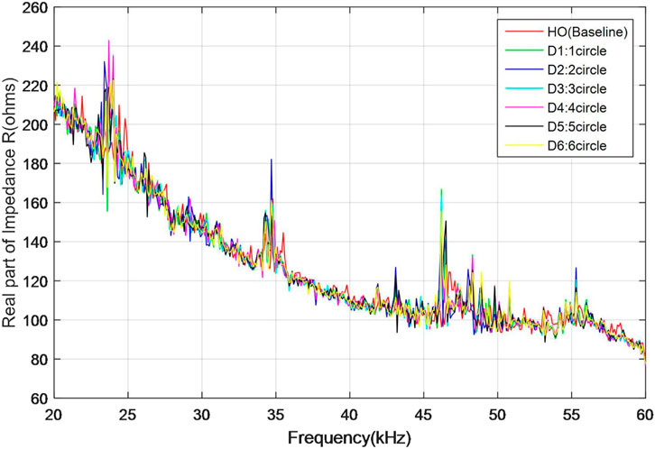
FIGURE 6. Measured electrical impedance signatures of the PZT patch by AD5933.
In order to quantitatively distinguish the differences, the root-mean-square distance (RMSD) algorithm was employed here to help to build a looseness detection index, thus the final identification result was presented in Figure 7. In the figure, it is observed that the RMSD-based looseness detection index increases in line with the increasing loosening severity of the connection. Based on the above analysis, it can be concluded that the AD5933 impedance evaluation board has an excellent ability to acquire the impedance signature of the host structure, and presents great potential for defect identification and hazard assessment.
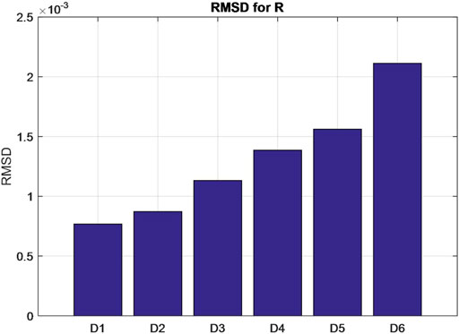
FIGURE 7. The calculated RMSD-based looseness index under different loosening severities.
Discussion
In this research, a cheap impedance evaluation board—AD5933—manufactured by the Analog Device Co., was experimentally studied to investigate its impedance calibration and measurement performance. At first, a simple impedance acquisition test for a free PZT patch was conducted to help to introduce the detail calibration procedure. Meanwhile, the PZT impedance signature measured by AD5933 was compared with the result measured by the professional impedance analyzer, WK6500B, and the final comparison result presents good consistency. Then, in order to further investigate the feasibility and effectiveness of AD5933 when applied in the real SHM field, especially for practical applications, a looseness disease detection test for a threaded pipeline connection was conducted, and the final results proved that the impedance measurement by AD5933 can be successfully utilized for the identifying loosening.
However, it should be noted that even though a free PZT patch and a loosening threaded pipe connection were experimentally investigated in this study, it is still necessary and meaningful to further validate the impedance measurement performance of the AD5933 board on more complex structures and in more practical applications. This related research will be conducted in our next work.
On the other hand, similar to the professional impedance analyzer, the accuracy and precision of the impedance measurement for the AD5933 board will also be significantly influenced by some external factors, including ambient temperature, moisture, environmental pressure, etc. For example, several researchers [37, 38] had experimentally verified that changing temperature will induce difference in EMI-based detection results, including magnitude changes or frequency shifts in measured impedance signatures. Even so, it still did not affect the ability and potential of EMI to be utilized as an impedance measurement device in the SHM and damage detection fields, especially for practical application.
In its current state, due to space limitation, the study is focused on verifying the feasibility of using the AD5933 board to acquire an impedance signature and realize damage identification for a host structure, especially detecting loosening in a threaded pipe connection.
Conclusion
In this study, a miniature impedance evaluation board, AD5933, was studied in detail to investigate its impedance calibration and measurement performance. Compared with the professional impedance analyzer, the AD5933 is much cheaper, has smaller dimensions and a much lower weight. In this research, a simple impedance measurement for a free PZT patch was investigated, and the acquisition signatures of the AD5933 presented a good consistency with the ones measured by the professional impedance analyzer. In addition, a threaded pipe connection specimen was assembled and tested in the laboratory to further validate the feasibility and effectiveness of the AD5933 board, especially performance in damage identification. The final results proved that the AD5933 board can be successfully utilized for loosening severity identification and quantification. Based on the above research, all the investigation results demonstrated that the AD5933 board has excellent ability in impedance measurement after proper calibration, and presents great potential in the area of structural health monitoring and damage detection, especially in practical application.
Data Availability Statement
The original contribution presented in the study are included in the article/Supplementary Material, further inquiries can be directed to the corresponding authors.
Author Contributions
All authors discussed and agreed upon the idea and made scientific contributions. YL developed the original idea, YL and QF designed the experiments, YL, YC, and ZZ conducted the experiments, YL and YC analyzed the data, YL and QF wrote the original draft. QF made critical revision to the paper.
Funding
The research was partially supported by the National Natural Science Foundation of China (Grant No. 51708520). The authors would like to thank for them for their financial support.
Conflict of Interest
YL, ZZ, and QF were employed by the company Wuhan Institute of Earthquake Engineering Co., Ltd.
The remaining authors declare that the research was conducted in the absence of any commercial or financial relationships that could be construed as a potential conflict of interest.
Publisher’s Note
All claims expressed in this article are solely those of the authors and do not necessarily represent those of their affiliated organizations, or those of the publisher, the editors, and the reviewers. Any product that may be evaluated in this article, or claim that may be made by its manufacturer, is not guaranteed or endorsed by the publisher.
References
1. Liang C, Sun FP, Rogers CA.An Impedance Method for Dynamic Analysis of Active Material Systems. J Vibration Acoust (1994) 116(1):120–8. doi:10.1115/1.2930387
2. Hu X, Zhu H, Wang D.A Study of concrete Slab Damage Detection Based on the Electromechanical Impedance Method. Sensors (2014) 14(10):19897–909. doi:10.3390/s141019897
3. Armstrong TW, Sevostianov I. Electrical Impedance Changes Due to Cracks in Planar Conductive Structural Elements. Struct Health Monit (2015) 14(5):489–501. doi:10.1177/1475921715596221
4. Wang D, Song H, Zhu H. Electromechanical Impedance Analysis on Piezoelectric Smart Beam with a Crack Based on Spectral Element Method. Math Probl Eng (2015) 2015:713501. doi:10.1155/2015/713501
5. Selva P, Cherrier O, Budinger V, Lachaud F, Morlier J. Smart Monitoring of Aeronautical Composites Plates Based on Electromechanical Impedance Measurements and Artificial Neural Networks. Eng Structures (2013) 56:794–804. doi:10.1016/j.engstruct.2013.05.025
6. Liang Y, Li D, Parvasi SM, Kong Q, Lim I, Song G. Bond-slip Detection of concrete-encased Composite Structure Using Electro-Mechanical Impedance Technique. Smart Mater Struct (2016) 25(9):095003. doi:10.1088/0964-1726/25/9/095003
7. Narayanan A, Kocherla A, Subramaniam KVL. Understanding the Coupled Electromechanical Response of a PZT Patch Attached to concrete: Influence of Substrate Size. Measurement (2018) 124:505–14. doi:10.1016/j.measurement.2018.04.055
8. Liang Y, Ye Z, Feng Q. Axial Load Monitoring for concrete Columns Using a Wearable Smart Hoop Based on the Piezoelectric Impedance Frequency Shift: a Feasibility Study. Adv Civil Eng (2020) 2020:1329516. doi:10.1155/2020/1329516
9. Liang Y, Li D, Parvasi SM, Song G. Load Monitoring of Pin-Connected Structures Using Piezoelectric Impedance Measurement. Smart Mater Struct (2016) 25(10):105011. doi:10.1088/0964-1726/25/10/105011
10. Huo L, Chen D, Liang Y, Li H, Feng X, Song G. Impedance Based Bolt Pre-load Monitoring Using Piezoceramic Smart Washer. Smart Mater Struct (2017) 26(5):057004. doi:10.1088/1361-665x/aa6a8e
11. Liang W, Zhang L, Xu Q, Yan C. Gas Pipeline Leakage Detection Based on Acoustic Technology. Eng Fail Anal (2013) 31:1–7. doi:10.1016/j.engfailanal.2012.10.020
12. Min J, Yi J-H, Yun C-B. Electromechanical Impedance-Based Long-Term SHM for Jacket-type Tidal Current Power Plant Structure. Smart structures Syst (2015) 15(2):283–97. doi:10.12989/sss.2015.15.2.283
13. Na W, Koh KH, Lee AS, Cho S, Ok B, Hwang S-W, et al. Binder-less Chemical Grafting of SiO2 Nanoparticles onto Polyethylene Separators for Lithium-Ion Batteries. J Membr Sci (2019) 573:621–7. doi:10.1016/j.memsci.2018.12.039
14. Park S, Yun CB, Inman DJ. Wireless Structural Health Monitoring Using an Active Sensing Node. Int J Steel Struct (2006) 6:361–8.
15. Min J, Park S, Yun CB, Song B. Development of a Low-Cost Multifunctional Wireless Impedance Sensor Node. Smart Structures Syst (2010) 6(5-6):689–709. doi:10.12989/sss.2010.6.5_6.689
16. Lin TH, Lu YC, Hung SL. Locating Damage Using Integrated Global-Local Approach with Wireless Sensing System and Single-Chip Impedance Measurement Device. ScientificWorldJournal (2014) 2014:729027. doi:10.1155/2014/729027
17. Wandowski T, Malinowski P, Ostachowicz W. Calibration Problem of AD5933 Device for Electromechanical Impedance Measurements. In: EWSHM-7th European Workshop on Structural Health Monitoring. Nantes, France: Nantes, France: Université de Nantes (2014).
18. Kaur N, Bhalla S, Shanker R, Panigrahi R. Experimental Evaluation of Miniature Impedance Chip for Structural Health Monitoring of Prototype Steel/RC Structures. Exp Tech (2016) 40(3):981–92. doi:10.1007/s40799-016-0097-6
19. Guo Z, Huang T, Schröder K-U. Development of a Piezoelectric Transducer-Based Integrated Structural Health Monitoring System for Impact Monitoring and Impedance Measurement. Appl Sci (2020) 10(6):2062. doi:10.3390/app10062062
20. Wandowski T, Malinowski PH, Ostachowicz WM. Improving the EMI-Based Damage Detection in Composites by Calibration of AD5933 Chip. Measurement (2021) 171:108806. doi:10.1016/j.measurement.2020.108806
21. Tawie R, Park HB, Baek J, Na WS. Damage Detection Performance of the Electromechanical Impedance (EMI) Technique with Various Attachment Methods on Glass Fibre Composite Plates. Sensors (2019) 19(5):1000. doi:10.3390/s19051000
22. Van Wittenberghe J, De Pauw J, De Baets P, De Waele W, Ost W, De Roeck G, et al. Fatigue Investigation of Threaded Pipe Connections. Ijsmed (2010) 1(1):182–9. doi:10.21825/scad.v1i1.20424
23. Van Wittenberghe J. Experimental Analysis and Modelling of the Fatigue Behaviour of Threaded Pipe Connections. [Doctoral dissertation]. Ghent (Belgium): Ghent University (2011).
24. Qu C-X, Yi T-H, Zhou Y-Z, Li H-N, Zhang Y-F. Frequency Identification of Practical Bridges through Higher-Order Spectrum. J Aerosp Eng (2018) 31(3):04018018. doi:10.1061/(asce)as.1943-5525.0000840
25. Qu CX, Yi TH, Li HN. Mode Identification by Eigensystem Realization Algorithm through Virtual Frequency Response Function. Struct Control Health Monit (2019) 26(10):e2429. doi:10.1002/stc.2429
26. Parvasi SM, Ji Q, Song G. Structural Health Monitoring of Plate-like Structures Using Compressive/Shear Modes of Piezoelectric Transducers. Earth and Space (2016) 1033.
27. Mishra A, Soni A. Leakage Detection Using Fibre Optics Distributed Temperature Sensing. In: 6th Pipeline Technology Conference (2011); New Delhi, India. engineers india limited (2011).
28. Zuo J, Zhang Y, Xu H, Zhu X, Zhao Z, Wei X, et al. Pipeline Leak Detection Technology Based on Distributed Optical Fiber Acoustic Sensing System. IEEE Access (2020) 8:30789–96. doi:10.1109/access.2020.2973229
29. Liang Y, Feng Q, Li D. Loosening Monitoring of the Threaded Pipe Connection Using Time Reversal Technique and Piezoceramic Transducers. Sensors (2018) 18(7):2280. doi:10.3390/s18072280
30. Liang Y, Feng Q, Li D, Cai S.Loosening Monitoring of a Threaded Pipe Connection Using the Electro-Mechanical Impedance Technique-Experimental and Numerical Studies. Sensors (2018) 18(11):3699. doi:10.3390/s18113699
31.Analog Device. Evaluation Board for the 1 MSPS, 12-Bit Impedance Converter, Network Analyzer, AD5933 DataSheet. Norwood, MA, USA: Analog Devices Inc. (2008).
33. Overly TGS, Park G, Farinholt KM, Farrar CR. Development of an Extremely Compact Impedance-Based Wireless Sensing Device. Smart Mater Struct (2008) 17(6):065011. doi:10.1088/0964-1726/17/6/065011
34. Ayres JW, Lalande F, Chaudhry Z, Rogers CA. Qualitative Impedance-Based Health Monitoring of Civil Infrastructures. Smart Mater Struct (1998) 7(5):599–605. doi:10.1088/0964-1726/7/5/004
35. Park G, Sohn H, Farrar CR, Inman DJ. Overview of Piezoelectric Impedance-Based Health Monitoring and Path Forward. Shock vib Dig (2003) 35(6):451–63. doi:10.1177/05831024030356001
36. Park G, Inman DJ. Structural Health Monitoring Using Piezoelectric Impedance Measurements. Phil Trans R Soc A (2007) 365(1851):373–92. doi:10.1098/rsta.2006.1934
37. Baptista F, Budoya D, Almeida V, Ulson J. An Experimental Study on the Effect of Temperature on Piezoelectric Sensors for Impedance-Based Structural Health Monitoring. Sensors (2014) 14:1208–27. doi:10.3390/s140101208
Keywords: electromechanical impedance, miniature impedance board, AD5933, threaded pipe connection, loosening monitoring
Citation: Liang Y, Chen Y, Zhang Z and Feng Q (2021) Experimental Evaluation of Miniature Impedance Board for Loosening Monitoring of the Threaded Pipe Connection. Front. Phys. 9:723260. doi: 10.3389/fphy.2021.723260
Received: 10 June 2021; Accepted: 12 July 2021;
Published: 31 August 2021.
Edited by:
Yang Zhang, Dalian University of Technology, ChinaReviewed by:
Tianyong Jiang, Changsha University of Science and Technology, ChinaKai Xu, Wuhan University of Science and Technology, China
Copyright © 2021 Liang, Chen, Zhang and Feng. This is an open-access article distributed under the terms of the Creative Commons Attribution License (CC BY). The use, distribution or reproduction in other forums is permitted, provided the original author(s) and the copyright owner(s) are credited and that the original publication in this journal is cited, in accordance with accepted academic practice. No use, distribution or reproduction is permitted which does not comply with these terms.
*Correspondence: Qian Feng, qfengwh@foxmail.com
†These authors have contributed equally to this work and share first authorship