Lead-Cooled Fast Reactor Annular UN Fuel Design and Development of Performance Analysis Program
 He Yuan1
  Guan Wang2,3
  Rui Yu2,3
  Yujie Tao2,3 Zhaohao Wang1 Shaoqiang Guo1
  Wenbo Liu1
  Di Yun1,4*
  Long Gu2,3,5*
- 1School of Nuclear Science and Technology, Xi’an Jiaotong University, Xi’an, China
- 2Institute of Modern Physics, Chinese Academy of Sciences, Lanzhou, China
- 3School of Nuclear Science and Technology, University of Chinese Academy of Sciences, Beijing, China
- 4State Key Laboratory of Multi-phase Flow, Xi’an Jiaotong University, Xi’an, China
- 5School of Nuclear Science and Technology, Lanzhou University, Lanzhou, China
A kind of annular uranium nitride (UN) fuel suitable for lead-cooled fast reactor applications has been designed in this study. The design is directly targeting two main issues of UN fuel: severe swelling and thermal decomposition of UN fuel at high temperatures. A performance analysis program based on FORTRAN programming language has been developed for UN fuel in fast reactors. The program contains heat transfer, fuel stress-strain analysis, cladding stress-strain analysis, fission gas release and fuel-cladding mechanical interaction (FCMI) modules, etc. Extensive code verification has been performed by comparing simulation results obtained with the code and those obtained via the COMSOL Multiphysics platform. Preliminary code validation has been conducted as well by comparing code simulation results with experimental data. The results showed that this program could predict the fuel temperature, stress-strain, and displacement of UN fuel during reactor operation with a reasonable accuracy.
Introduction
With the rapid development of the fast reactor technology, nitride fuel applied in lead-cooled fast reactors has attracted much attention, and nitride fuel is considered as one of the advanced fast reactor fuels (Yun et al., 2021; Glazov et al., 2007). Uranium nitride, as the main form of nitride nuclear fuel, is superior to conventional oxide fuels (MOX, UO2) in multiple ways (see Table 1): it possesses higher heavy metal density as compared to oxide fuels, increasing the conversion ratio (CR); it has better thermal conductivity; the thermal conductivity increases as the temperature increases, which provides the fuel with better performance under transient conditions; and the fissile inventory ratio of UN is 10% higher than that of MOX fuel (Bo et al., 2013). However, the performance of UN fuels also suffers from two important drawbacks: severe fuel swelling and thermal decomposition at high temperature, which tend to limit the development of UN fuel applications in fast reactors (Bauer et al., 1979; Lunev et al., 2016). In order to achieve better performance of UN fuel in fast reactors, this paper is targeting to resolve the above issues by carrying out a new kind of annular fuel design. In addition, it was found that there are very few performance analysis programs for UN fuel in fast reactors at present, among which there is basically none for annular UN fuel. For the development and application of UN fuel, it is necessary to have a set of performance analysis programs to be capable of analyzing and predicting the fuel behaviors under normal and transient operations.
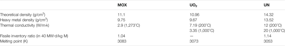
TABLE 1. Comparison of basic performance of MOX, UO2 and UN (Arai, 2012; Bo et al., 2013).
Fuel Design
The fuel design described in this paper targets to resolve the inherent deficiencies of the fuel and enable the fuel to operate over an extensive fuel life. Although the UN fuel has a very high melting point, it will start to decompose at about 2000 K due to low partial pressure of nitrogen (Bo et al., 2012; Lunev et al., 2016). Therefore, the fuel pellet temperature should be kept strictly below 2000 K when the reactor is in operation. Fuel swelling can be categorized into solid fission product (FP) swelling and gaseous FP swelling. In order to prevent extensive solid FP swelling, the designers usually allocate enough space in the fuel (usually by porosity introduced in the manufacturing process) to accommodate swelling by solid FPs; gaseous FP swelling, on the other hand, is greatly affected by temperature. According to Colin (Colin et al., 1983), the fuel will be in a state with little fission gas release and minimal swelling at temperatures less than 1423 K. This is commonly referred to as the “cold fuel” concept. Therefore, one of the purposes of the fuel design in this work is to ensure that the pellet temperature is kept below 1423 K under normal operation conditions.
In this paper, a kind of single-clad annular fuel design (as opposed to annular fuel design for PWR with inner and outer clad) is introduced. Shown in Figure 1 are comparative analyses of the temperature distributions were conducted with the aid of the finite-element platform, COMSOL Multiphysics, for three sets of rod fuel designs and two sets of annular fuel designs with different fuel-cladding gap sizes while maintaining the same operating conditions. For the rod fuel design with a gap of 0.2 mm (the maximum gap size allowed in the annular fuel design standard) (Arai, 2012), there is more space to accommodate FP swelling compared to other rod fuel designs, but the fuel maximum temperature (at the inner most location of the fuel) is already much higher than 1423 K. Although the maximum temperature of the rod fuel design with the gap of 0.08 mm does not exceed the limiting value of 1423 K, there is a very high risk that the fuel maximum temperature exceeds the threshold temperature when the reactor power increases under transient conditions, and therefore this kind of design is not considered to be optimal. For the annular fuel design with a gap of 0.08 mm, although the central temperature of 1340 K can meet the temperature threshold value requirements, the annular fuel design with the gap of 0.04 mm obviously has larger safety margin, which is more in line with the reactor design criteria; For the rod fuel design with a gap of 0.04 mm, although the central temperature is significantly lower than the threshold value, FCMI may emerge as a more serious problem due to the small gap size. On the one hand, the annular design, which can move the heat source of fuel more outward and reduce the fuel-cladding gap size, can help enhance the heat transfer to achieve lower fuel maximum temperature; on the other hand, because of the central hole structure, if the fission products cause excessive swelling strain under high burnup, the pellet may swell inward to partially relieve the stress between fuel and cladding and hence to help maintain the structural integrity of the fuel-clad system.
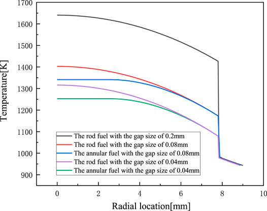
FIGURE 1. Steady-state operating temperature of five different designs of fuel in 45 kW/m.
With the above stated rationale, a novel design of single-clad annular UN fuel suitable for fast reactor applications is proposed (as schematically shown in Figure 2, where the structural components of the fuel-cladding system are labeled from the outside to the inside in the following order: cladding, helium gap, UN fuel, and central hole).
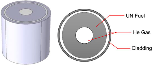
FIGURE 2. The annular UN fuel design.
Fuel Design Advantages
Annular fuel design can reduce the maximum temperature to the range that is ideal for well restrained fission gas swelling (< 1423 K). This relatively low temperature for fast spectrum reactors may be achieved not only because of the annular geometry design but also because of the inherent excellent thermal conductivity of UN fuel. The UN fuel temperature distribution is hereby compared with the most widely used MOX fuel in fast reactors with the same geometry design and volumetric heat rate and the results are demonstrated in Figure 3. It can be seen that the central temperature of MOX fuel is about 500 K higher than that of UN fuel and the MOX fuel average temperature is also much higher than that of UN fuel (Figure 3A). From Figure 3B, the reason for this temperature distribution comparison may easily be identified to be the rather ideal thermal conductivity of UN fuel.
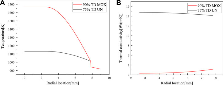
FIGURE 3. Comparison of MOX and UN. (A) temperature distribution. (B) thermal conductivity (Hales et al., 2013).
Reactivity Initiated Accidents (RIA) events would cause a rapid increase in power in a short time, and affect the safety of fuel elements. To demonstrate the transient behaviors of the UN fuel design, the power was increased to 200% of the normal operation power at 55 s and then restored to the normal operation power within 0.5 s. The changes in the maximum temperature of the fuel and the cladding are calculated and shown in Figure 4. The pellet central temperature reached a maximum of 1181 K in 55.5 s, which is only 50 K higher than its steady state counterpart. The cladding inner temperature is only 10 K higher than its steady state counterpart. Reasons for such small temperature changes are the followings: on the one hand, in comparison with the rod type fuel, the design of the annular pellet moves the heat source towards the outer side, and heat is more easily carried away by the coolant; on the other hand, UN fuel has better thermal conductivity, and the thermal conductivity increases as the temperature increases, which provides the fuel with better performance under transient conditions.
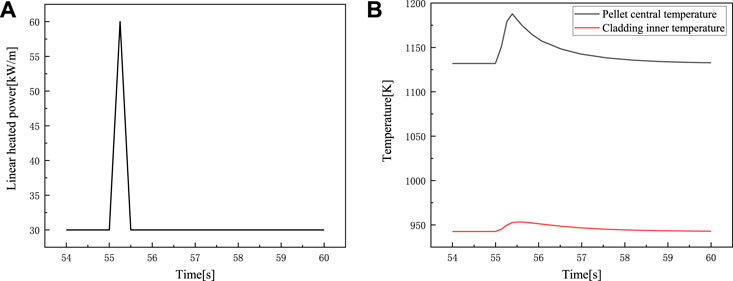
FIGURE 4. Reactivity Initiated Accidents events. (A) the change of linear heated power. (B) the change of the maximum temperature of pellet and cladding.
Fuel Behaviors Modeling
Fuel Heat Transfer Module
The temperatures of the pellet and cladding during reactor operation are very important parameters that directly affect the fuel swelling, fission gas release and FCMI, etc. Thus, fuel temperature is the most fundamental part of fuel performance analysis. The heat transfer process inside the pellet and the cladding is described by the following heat transfer equation:
where
For the steady-state case, the time differential term on the left-hand side of the equation is zero.
The relation given by Rogozkin (Yun et al., 2021) has been adopted for the UN fuel thermal conductivity in this work:
where p is the porosity (%), and this correlation is suitable for fuel temperature in the range 298 K < T < 1923 K.
Pellet Mechanical Analysis Module
In modeling the mechanical behaviors of the fuel, the following assumptions were made for the mechanical analysis module.
1) Continuity assumption, where the pellets remain close to each other at adjacent mesh points before and after deformation, and neither pores nor overlaps are created;
2) The axisymmetric assumption;
3) The generalized plane strain assumption;
4) The isotropic assumption;
5) The quasi-static assumption, ignoring the inertia effect of the structure.
The generalized Hooke’s law was used to describe the stress-strain relationship (Karahan, 2010). The total strain is comprised of thermal expansion, swelling, creep strain, and the elastic term, which takes the form of:
where E is Young’s modulus (Hayes et al., 1990a) [Pa],
An empirical formula by Ross (El-Genk et al., 1987) was adopted as the swelling strain model for UN fuel from fuel irradiation data of the U.S. space reactor project, and it is as follows:
Where
Fuel creep is specifically divided into two parts: irradiation creep and thermal creep, with irradiation creep playing a dominant role at low temperatures and thermal creep playing a dominant role at high temperatures.
The irradiation creep model is as follows (Billone et al., 1977):
where f is fission rate (fission/cm3/s).
The thermal creep model is as follows (Hayes et al., 1990b):
Cladding Mechanical Module
The material selected for cladding is HT-9 steel, whose stress-strain constitutional equations are consistent with those of the pellet as has been described in the above.
The thermal creep model for HT-9 steel consists of primary creep, secondary creep and tertiary creep, and it is as follows (Ryu et al., 2006):
The irradiation creep correlation is as follows (Toloczko and Garner, 1999):
where
Fission Gas Release Module
Fission gas release is affected by fuel burnup, pellet porosity and temperature, but there is no complete and accurate mechanistic models to describe the fission gas release in UN fuel. The empirical relationship proposed by Storms (Storms, 1988) through summarizing 134 sets of nitride fuel rod data is used here:
where R is the FP gas release rate (%), D is the actual fuel density (% TD), Bu is the fuel burnup (%), and T is the temperature of fuel [K].
Code Verification and Validation
Verification on Heat Transfer Analysis
As the temperature distribution profile across the pellet and cladding strongly affects the fuel swelling and fission gas release rate, the heat transfer model needs to be verified in the first place. Figure 5 shows the temperature profile calculated by the code developed in this work and that calculated by COMSOL Multiphysics at steady-state operation condition of 30 kW/m with a coolant temperature of 873 K. According to the comparison, the temperature profiles calculated by our code and by the COMSOL platform are nearly the same, and the maximum difference at any radial location is about 3 K, which proves that the calculated temperature result of our code is accurate. The maximum temperature of the fuel is kept around 1130 K, which is far below the threshold value of 1423 K providing an adequate safety margin.
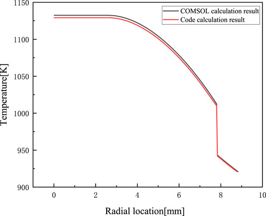
FIGURE 5. The comparison of temperature between the calculation results of code and COMSOL.
Verification on Pellet Mechanical Analysis
The strain components of the pellet include elastic strain, thermal expansion strain, swelling strain, thermal creep and irradiation creep strains, and the stress component is divided into three principal directions: radial, circumferential and axial. The accuracy of the stress-strain calculation of the pellet directly affects the analysis of FCMI, where the calculation of swelling is the central concern. Figure 6 shows the variation of volumetric swelling versus burnup with an average fuel temperature of 1087 K for rod type fuel. The results of the code calculation are relatively close to the empirical correlation, and there are still numerical differences because the empirical correlation is a correlation for UN fuels with a gross fuel temperature range below 1400 K (Bauer et al., 1971); Thus, calculation by our code is done with a temperature that is somewhat different from those at which the correlation was obtained; Similarly, the temperatures at which the experimental data were measured were also in a gross range near 1100 K (El-Genk et al., 1987; Bo et al., 2013), leading to the difference between the experimental values and the code calculation results.
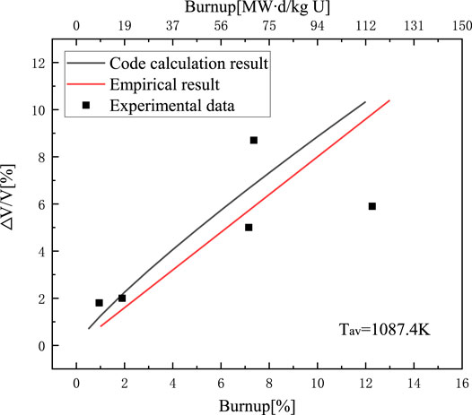
FIGURE 6. Fuel volume swelling versus burnup.
Another very important parameter to gauge the accuracy of the code calculation is the fuel and cladding displacement, which is a most intuitive reflection of the mechanical state of the pellet. Figure 7 compares the displacements of the pellet within 1,000 days by our code and by COMSOL calculation.
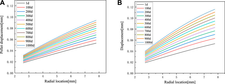
FIGURE 7. Pellet displacement calculation results. (A) the code calculation result. (B) COMSOL calculation result.
Since the fuel design is a new kind of design, no experimental data on the mechanical state of the fuel-clad system can be found. To verify the accuracy of the calculation results, the results by our code and by COMSOL at 1, 100, 500 and 1,000 days were compared. The trends of displacement matched each other reasonably well, and the size deviations are in an acceptable range as shown in Figure 8. The results of both calculations are basically the same at 1 day, and the deviation increases with time. The reason for this deviation is that our code calculation was carried out under the generalized plane strain condition, while the COMSOL calculation was carried out under the plane strain condition. Because the amount of swelling increases versus time, the difference between the calculated displacement results become larger versus time. Overall, the code calculation results should be more accurate than the COMSOL calculation results. As the generalized plane strain assumption was adopted in the code, while the plane strain assumption was adopted in COMSOL, the initial axial pre-strain had to be set in COMSOL in order for the calculation results by the two different methods to be comparable. The axial strain in the code, however, was updated iteratively, rendering such calculation to be closer to the reality.
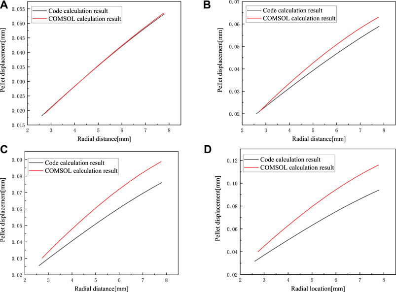
FIGURE 8. (A) (B) (C) (D) are the displacement comparison results of the fuel at 1, 100, 500, and 1,000 days.
Verification on Cladding Mechanical Analysis
The strain components of the cladding mainly include elastic strain, thermal expansion strain and creep strain, and the swelling of the cladding material is almost negligible. Like the pellet stress-strain model, the cladding stress-strain model directly affects FCMI, which has very important implications for reactor fuel safety. Figure 9 shows the comparison between our code calculation and COMSOL calculation results at 1 and 1,000 days. The calculation results of Figure 9A and Figure 9B are almost the same because the cladding displacement is mainly caused by thermal expansion, but thermal expansion strain is only related to temperature, not time.
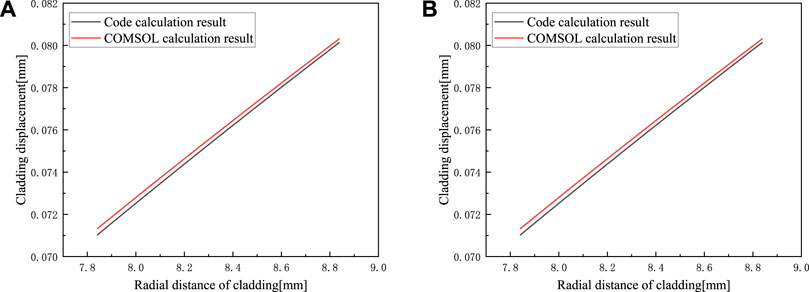
FIGURE 9. Comparison of displacement results of the cladding, (A) at 1 day, (B) at 1,000 days
Comparison of Fission Gas Release
At temperatures below 1423 K, the fission gas release rate is relatively low, which is one of the key features of our fuel design concept. Figure 10 shows the fractional fission gas release results for our UN fuel design operating at 30 kW/m up to 8% (75 MW d/kg U) burnup. It is demonstrated that the code calculations results are in good accordance with experimental data (Storms, 1988).
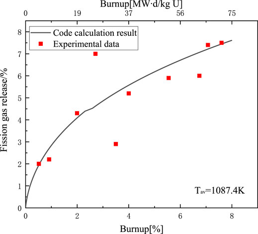
FIGURE 10. Fractional fission gas release versus burnup.
Fuel Behaviors Assessments
To determine the effect of porosity on the heat transfer of fuel pellets, the code was used to simulate the effects of 25 and 15% porosity (Arai, 2012), respectively. From Figure 11, it can be seen that the maximum fuel temperatures for both cases are well below 1423 K. The fuel maximum temperature with 25% porosity is about 25 K higher than that of fuel with 15% porosity. On the other hand, if the fuel porosity increases, the increased open volume can help accommodate the fission products, delay the fuel-cladding contact time, and reduce FCMI. Therefore, from the perspective of reducing FCMI while not increasing fuel temperature to an unacceptable extent, 25% fuel porosity is better than 15% fuel porosity. However, increased fuel porosity tends to bring about more issues in fuel cracking and mechanical behaviors. Thus, the choice of a proper porosity level highly depends on the achievable fuel plasticity when such porosity is realized in the actual manufacturing process.
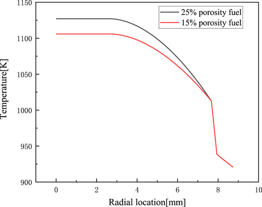
FIGURE 11. The influence of 25 and 15% porosity in heat transfer results.
The evolution of contact pressure and gap size, with a constant 30 kW/m linear heat rate for 5 years of continuous operation, was calculated by our code and is shown in Figure 12. The contact of pellet and cladding starts at about 1,500 days. Before contact, the contact pressure is always equal to the gap pressure, which is affected by fission gas released, and the gap size is gradually reduced. After contact, the contact pressure starts to increase and the gap size is equal to zero.
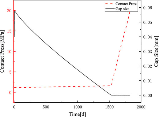
FIGURE 12. The change of contact press and gap size versus time.
In a ceramic fuel that is usually stiff, the swelling of fuel that leads to significant FCMI is often a severe issue. In our fuel design, the central hole not only serves a purpose of lowering the fuel temperature but also provides a means to relieve FCMI. In order to demonstrate this aspect of the fuel design, the evolution of displacement of the inner surface of the pellet was calculated for a total length of 6.5 years. Figure 13 shows that the inner surface displaces outward at first, and the speed of this outward displacement slows down at 4.1 years (1,500 days). Then the fuel pellet displaces inward at 5.7 years (2,100 days). It is perceivable that the pellet and cladding are in contact at 4.1 years, and the contact pressure reaches the maximum of about 30 MPa at 5.7 years before the pellet inner surface starts to move inward and the contact pressure does not further increase thereafter. It is thus demonstrated that the annular design component is effective in mitigating the FCMI issue in the long run.
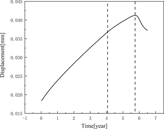
FIGURE 13. The displacement of the inner surface of pellet versus time.
Conclusion and Prospects
In this work, a kind of annular UN fuel for a lead-cooled fast reactor was designed with considerations of the two main drawbacks of UN fuel (thermal decomposition and severe swelling at high temperatures). This design targets to resolve these issues by a single-clad annular design that reduces the fuel central temperature to about 1130 K. In addition, a fuel performance analysis code was developed for lead-cooled fast reactor annular UN fuel, which can be used to analyze fuel temperature distribution, pellet stress-strain, cladding stress-strain, fission gas release, FCMI and gap size. Preliminary assessments demonstrated that the code could analyze UN fuel performance with reasonable accuracy. Through calculation results of the code, the behaviors of the annular UN fuel design were assessed which further validated the design concept. This work, thus, provides some fundamental data to assist the development and applications of UN fuel.
Data Availability Statement
The raw data supporting the conclusions of this article will be made available by the authors, without undue reservation.
Author Contributions
DY and HY contributed to conception and design of the study. HY and GW completed the programming of the code. HY completed the simulation comparison of COMSOL. DY, HY and GW performed the statistical analysis. HY wrote the original draft. All authors contributed to manuscript revision, read, and approved the submitted version.
Funding
This work was supported by the State Key Research and Development Program of China, Grant No. 2020YFB1902100, and the National Natural Science Foundation of China, Grant Nos. 11675126 and 11705255. Special fund of Shanghai Economic and Information Technology Commission (approved number: GYQJ-2018-2-02) is also acknowledged.
Conflict of Interest
These authors declare that the research was conducted in the absence of any commercial or financial relationships that could be construed as a potential conflict of interest.
Publisher’s Note
All claims expressed in this article are solely those of the authors and do not necessarily represent those of their affiliated organizations, or those of the publisher, the editors and the reviewers. Any product that may be evaluated in this article, or claim that may be made by its manufacturer, is not guaranteed or endorsed by the publisher.
References
Arai, Y. (2012). Nitride Fuel[J]. Compr. Nucl. Mater. 3, 41–54. doi:10.1016/b978-0-08-056033-5.00050-1
Bauer, A. A., Brown, J. B., Fromm, E. O., and Storhok, V. W. (1971). MIXED-NITRIDE FUEL IRRADIATION PERFORMANCE. Columbus, OH: Battelle Memorial Institute.
Bauer, A. A., Petty, P., and Muth, R., In Proceedings of Topical Meeting on Fast Breeder Reactor Fuel Performance[J]. 1979: p 827–841.
Billone, M., Jankus, V., Kramer, J., and Yang, C. L. (1977). Progress in Modeling Carbide and Nitride Fuel Performance in Advanced LMFBRs, in Advanced LMFBR Fuels.
Bo, F., Karahan, A., and Kazimi, M. S. (2012). Steady-state Fuel Behavior Modeling of Nitride Fuels in FRAPCON-EP[J]. J. Nucl. Mater. 427 (1-3), 30–38. doi:10.1016/j.jnucmat.2012.04.011
Bo, F., Kazimi, M. S., and Forget, B. (2013). Feasibility of Breeding in Hard Spectrum Boiling Water Reactors with Oxide and Nitride Fuels. Mass. Inst. Technol, 148–149.
Colin, M., Coquerelle, M., Ray, I., Ronchi, C., Walker, C. T., and Blank, H. (1983). The Sodium-Bonding Pin Concept for Advanced Fuels Part I: Swelling of Carbide Fuel up to 12% Burnup[J]. Nucl. Technol. 63 (3), 442–460. doi:10.13182/nt83-a33271
El-Genk, M. S., Ross, S. B., and Matthews, R. B. (1987). Uranium Nitride Fuel Swelling and thermal Conductivity Correlations. Space Nuclear Power Systems, 313–317.
Glazov, A. G., Leonov, V. N., Orlov, V. V., Sila-Novitskii, A. G., Smirnov, V. S., Filin, A. I., et al. (2007). Brest Reactor and Plant-Site Nuclear Fuel Cycle. At Energy 103 (1), 501–508. doi:10.1007/s10512-007-0080-5
Hales, J. D., Novascone, S. R., Pastore, G., and Pe, D. M. (2013). BISON Theory Manual the Equations behind Nuclear F[J]. Idaho National Lab. doi:10.2172/1107264
Hayes, S. L., Thomas, J. K., and Peddicord, K. L. (1990). Material Property Correlations for Uranium Mononitride II. Mechanical Properties[J]. J. Nucl. Mater. 171 (2-3), 271–288. doi:10.1016/0022-3115(90)90375-w
Hayes, S. L., Thomas, J. K., and Peddicord, K. L. (1990). Material Property Correlations for Uranium Mononitride[J]. J. Nucl. Mater. 171 (2-3), 289–299. doi:10.1016/0022-3115(90)90376-x
Karahan, A. (2010). Modelling of Thermo-Mechanical and Irradiation Behavior of Metallic and Oxide Fuels for Sodium Fast Reactors[J]. J. Nucl. Mater. 396 (2-3), 272–282.
Lunev, A. V., Mikhalchik, V. V., Tenishev, A. V., and Baranov, V. G. (2016). Kinetic and Microstructural Studies of thermal Decomposition in Uranium Mononitride Compacts Subjected to Heating in High-Purity Helium. J. Nucl. Mater. 475, 266–273. doi:10.1016/j.jnucmat.2016.04.018
Ryu, H. J., Yacout, A., Kim, Y., and Hofman, G. (2006). Review of HT-9 Cladding Creep Correlations for Advanced Liquid Metal Fast Reactors[J]. Trans. Am. Nucl. Soc. 94, 797–798.
Storms, E. K. (1988). An Equation Which Describes Fission Gas Release from UN Reactor Fuel. J. Nucl. Mater. 158, 119–129. doi:10.1016/0022-3115(88)90161-4
Toloczko, M. B., and Garner, F. A. (1999). Variability of Irradiation Creep and Swelling of HT9 Irradiated to High Neutron Fluence at 400–600°C[C], Effects of Radiation on Materials: 18th International Symposium, 765–779. doi:10.1520/stp13902s
Keywords: UN fuel, annular fuel, fuel performance analysis, COMSOL, fast reactors
Citation: Yuan H, Wang G, Yu R, Tao Y, Wang Z, Guo S, Liu W, Yun D and Gu L (2021) Lead-Cooled Fast Reactor Annular UN Fuel Design and Development of Performance Analysis Program. Front. Energy Res. 9:705944. doi: 10.3389/fenrg.2021.705944
Received: 06 May 2021; Accepted: 13 July 2021;
Published: 27 July 2021.
Edited by:
Zhang Chunyu, Sun Yat-Sen University, ChinaCopyright © 2021 Yuan, Wang, Yu, Tao, Wang, Guo, Liu, Yun and Gu. This is an open-access article distributed under the terms of the Creative Commons Attribution License (CC BY). The use, distribution or reproduction in other forums is permitted, provided the original author(s) and the copyright owner(s) are credited and that the original publication in this journal is cited, in accordance with accepted academic practice. No use, distribution or reproduction is permitted which does not comply with these terms.
*Correspondence: Di Yun, diyun1979@xjtu.edu.cn; Long Gu, gulong@impcas.ac.cn