Autonomous Cooperative Control for Hybrid AC/DC Microgrids Considering Multi-Energy Complementarity
 Dan Zhou1*
  Shangren Chen
- College of Information Engineering, Zhejiang University of Technology, Hangzhou, China
- 2State Grid Huzhou Power Supply Company, Huzhou, China
- 3Huzhou Xinlun Comprehensive Energy Service Co., Ltd., Huzhou, China
Multi-energy hybrid AC/DC microgrids (MGs), considering ice storage systems (ISSs), can promote the flexible integration and efficient utilization of distributed generators (DGs) and energy storage systems (ESSs), provide a reliable power supply for local loads, and achieve multi-energy complementarity and energy savings at the same time. An autonomous cooperative control of multi-energy MGs is proposed in this paper, which can realize the following targets: 1) In the energy storage period, ice storage systems and energy storage systems can absorb energy in accordance with their rated capacity. 2) In the energy releasing period, ice storage systems are first put into operation, and the rest of the equivalent cooling loads and electrical loads are shared by the energy storage systems according to their rated capacity ratio. Besides, the complete system small signal model is constructed, which can be used to analyze the features and characteristics of the system and guide the optimal design of the control parameters. Finally, the effectiveness of the proposed control is corroborated by several case studies conducted in PSCAD/EMTDC.
Introduction
In recent years, an increasing number of electrical generation sources are being replaced by renewable energy sources (RESs), such as wind turbines and photovoltaic (PV) panels, which are more sustainable and environmentally friendly (Bouzid et al., 2015; Kerdphol et al., 2018). Microgrids are treated as an effective way to integrate RESs and loads together, which have attracted much attention worldwide (Alegria et al., 2014; Huang et al., 2019). A microgrid (MG) refers to a small-scale power generation and distribution system, which is comprised of distributed generators (DGs), energy storage systems (ESSs), loads, and monitoring and protection devices (Wei et al., 2021; Wang, 2013). MG can improve utilization efficiency of renewable energy systems (RESs, PV, wind power, etc.) and improve the reliability of the power supply and power quality efficiently (Yang et al., 2014; Gupta et al., 2018). It can work in grid-connected mode and islanded mode (Lu et al., 2007; Ouammi et al., 2015). In the islanded mode, microgrids can provide a power supply to remote areas or islands (Wang et al., 2016; Pashajavid et al., 2017). It has been proven that a MG is one of the most effective ways to utilize DGs in distribution systems (Parhizi et al., 2015).
Compared to a pure AC MG or a DC MG, which need corresponding DC/AC converters to connect with AC (or DC) sources and loads, a hybrid AC/DC MG can integrate AC and DC DGs and loads, which reduces the power conversion process and improves energy conversion efficiency (Loh et al., 2013a; Loh et al., 2013b; Unamuno and Barrena, 2015; Jia et al., 2018; Su et al., 2019). Besides, if adjacent AC MGs and DC MGs can be flexibly interconnected in the form of clusters, the system can accept AC and DC renewable energy systems and loads efficiently, and the reliability and operation stability of the whole system can be enhanced (He and Giesselmann, 2015; Xia et al., 2018a; Xia et al., 2018b; Wei et al., 2019a; Cheng et al., 2019). The control strategy for hybrid AC/DC MGs is the key to maintaining stable operation and realizing the matching targets of the system, such as smooth power transfer (Liu et al., 2011). Matching power transfer between microgrids enables maximum utilization of distributed energy resources, a cluster-oriented cooperative control strategy for multiple AC micro-grid clusters is proposed in (Lai et al., 2019). In (Jena and Padhy, 2020), to address the problem of power sharing in networked hybrid AC/DC micro-grid clusters, The hierarchical distributed cooperative control strategy is employed for both the AC and DC microgrid clusters for enabling power sharing among the clusters according to the required needs. In order to solve the influence of line resistance on the hybrid AC/DC microgrid composed of multiple interlinking converters, an autonomous power sharing approach for hybrid microgrids interconnected through multiple interlinking converters by introducing a superimposed frequency in the DC subgrids is proposed in (Peyghami et al., 2018). A hybrid AC/DC microgrid with multiple subgrids adopt a proper power management method, which can achieve the power sharing and mutual supporting described in (Xia et al., 2018b). To suppress the circulating currents and realize the proper power interaction, a decentralized coordination control is proposed in (Yang et al., 2018). To cope with uncertainty and fluctuations of the output power of RESs, a robust optimal coordinated control for multiple VSCs in an AC-DC distribution network is used in (Sun et al., 2019), which can enhance the robustness of the system and realize optimal power allocation.
Ice storage systems emerged in the 1980’s. By using ice as an energy storage medium, large air-conditioning systems can store energy in the low power supply period and supply cooling load in the peak power supply period of a power grid. Ice storage systems have the following advantages: 1) alleviating the shortage of power supply during the peak power supply period and 2) using peak-valley electricity pricing of different areas to save electricity costs (Ding et al., 2014; Ge et al., 2017; Yang et al., 2017; Wei et al., 2019a). A comprehensive energy efficiency evaluation of a hybrid system integrating a ground source heat pump and ice storage technologies in an office building is given in (Zhang, 2016). An economically optimal control strategy for dynamic ice storage systems is proposed in (Yan et al., 2016). However, the aforementioned studies do not consider how to achieve flexible control when hybrid AC/DC microgrids adopt an ice storage system.
The structure of a multi-energy microgrid is shown in Figure 1 and has the following characteristics: 1) multiple AC microgrids and DC microgrids are connected to a common DC bus through power electronic interfaces in parallel, which can efficiently and flexibly accept DGs and ESSs to provide a high reliability power supply for local loads; and 2) ice storage systems are integrated into the multi-energy microgrid, and through a certain control strategy, multi-energy complementarity can be realized, which improves energy utilization flexibility.
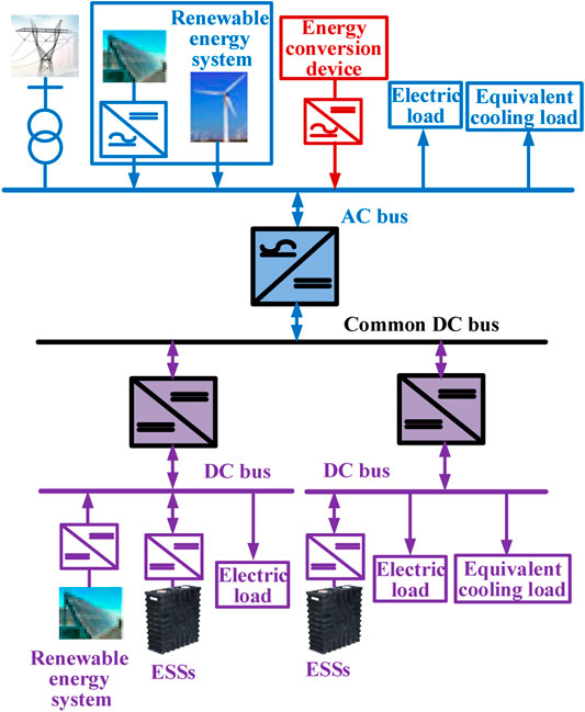
FIGURE 1. Structure of a multi-energy microgrid.
In this paper, an autonomous cooperative control strategy is proposed for a multi-energy microgrid system as shown in Figure 1. The following control targets are expected to be achieved:
1) The power balance and the stability of common DC bus voltage, DC voltages and AC frequency voltage are maintained through the autonomous cooperative control strategy.
2) In the energy storage period, an ice storage system and ESSs can reasonably absorb electric energy according to their rated capacities. In the energy releasing period, the ice storage system should first be put into operation. The equivalent loads of the remaining cooling load and electric loads should be reasonably shared by ESSs according to their rated capacity ratio.
Equivalent Structure of Multi-Energy Microgrids
To facilitate the description of the autonomous cooperative control strategy proposed in this paper, an equivalent structure of the multi-energy microgrids is depicted in Figure 2, which includes one AC microgrid and two DC microgrids. Each microgrid contains one total balance unit (representing energy conversion devices, ESSs and controllable distributed power supplies, etc.) and one total power unit (such as RESs, loads, etc.). The balance unit is used as the main power source to maintain the stability of the AC voltage/frequency in AC microgrids or DC voltage in DC microgrids. Renewable energy generation units with maximum power point tracking control (MPPT), energy storage units and loads in a power dispatch mode can be regarded as power units. The AC and DC microgrids are connected to the common DC bus through corresponding power electronic interfaces in parallel (DC-AC or DC-DC).
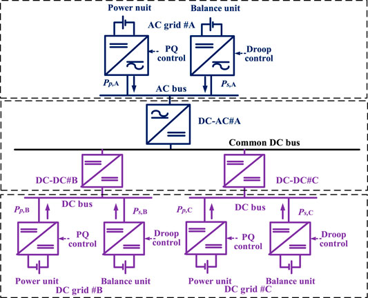
FIGURE 2. Equivalent structure of multi-energy microgrids.
Autonomous Cooperative Control of Multi-Energy Microgrids
Control Structure and Targets of Multi-Energy Microgrids
To realize the stability control of multi-energy microgrids as shown in Figure 2, A basic control framework of autonomous cooperative control for multi-energy microgrids is proposed, as shown in Figure 3. In this paper, the following main operation functions are expected to be realized with the proposed control.
1) The physical layer of the multi-energy microgrid is composed of an AC microgrid and DC microgrid. The AC and DC microgrids are controlled by the corresponding local controllers and central controllers, respectively. Each microgrid realizes autonomous control by the corresponding local controllers and cooperative control through the central controllers.
2) Each microgrid can accept dispatching instructions from central controllers, and through a certain control strategy, multi-energy complementarity and optimization targets can be realized.
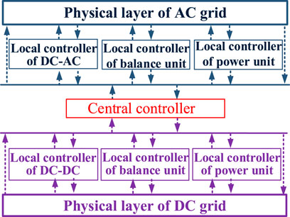
FIGURE 3. Basic framework for autonomous cooperative control for a multi-energy microgrid.
Based on the above framework, an autonomous cooperative control strategy for a multi-energy microgrid is proposed to achieve the following control targets:
1) Energy storage period: ice storage systems and ESSs can reasonably absorb electric energy according to their rated capacities. As shown in Figure 2, the net power of the power units found in the three microgrids are Pp,A, Pp,B and Pp,C respectively, which flow the corresponding bus in the positive direction. In this paper, assuming that the rated capacities of AC microgrid #A, DC microgrid #B and DC microgrid #C are Pos,A, Pos,B and Pos,C respectively, and that their capacity ratios satisfy Pos,A: Pos,B: Pos,C = a: b: 1. When the multi-energy microgrid works normally, it is expected that the actual energy storage powers Ps,A, Ps,B and Ps,C of balance units in AC microgrid #A, DC microgrid #B, and DC microgrid #C, respectively, can be reasonably shared by each balance unit according to its rated capacity ratio (a:b:1), which can improve the utilization efficiency of the balance units in the multi-energy microgrid.
2) Energy releasing period: when in the peak power supply period, ice storage systems should be put into operation first. Then, the equivalent loads of the remaining cooling load and electric loads can be reasonably shared by the balance units according to their rated capacity ratio.
Control Strategy of the Balance Units in the AC/DC Microgrids
Control Strategy for the Balance Units in an AC Microgrid
As shown in Figure 2, the power unit in AC microgrid #A adopts constant power control, and the balance unit adopts double loop control, as shown in Supplementary Figure S1. The outer loop generates phase signal θA and voltage amplitude signal Vref,A of the voltage reference for the voltage inner loop through P-f control and Q-V droop control. Then, the voltage inner loop control generates control signals to realize the final control target. To reduce steady-state error and improve the dynamic response of the control system, the voltage inner loop always adopts PR control.
It can be seen from Supplementary Figure S1 that the power output and frequency of the balance unit of AC microgrid #A has the following droop characteristic:
where ωA, ωset,A and Ps,A represent the actual frequency, the frequency setting value of the droop control and the power output of the balance unit of AC microgrid #A, respectively; kp,A represents the droop coefficient of P-f droop control. Meanwhile, as seen in Supplementary Figure S1, kp,A represents the droop coefficient of Q-V droop control; kpu,A, kru,A, ω0 and ωc0 are the proportional coefficient, resonance coefficient, resonance frequency and error frequency of the PR controller; vpwm,A and us,A are control signals of the voltage inner loop control and the voltage output of the balance unit of AC microgrid #A.
Control Strategy for the Balance Units in a DC Microgrid
As shown in Figure 2, the power unit in DC microgrid #i (i = B, C) adopts constant power control, and the balance unit adopts double loop control, as shown in Supplementary Figure S2. The outer loop generates voltage reference uref,i for the inner loop through P−V droop control. Then, the voltage/current inner loop control generates control signals to realize the final control target.
It can be seen from Supplementary Figure S2 that the power output and DC voltage of the balance unit of DC microgrid #i (i = B, C) has the following droop characteristic:
where ui and Ps,i represent the actual DC voltage and power output of the balance unit of DC microgrid #i, respectively; uset,i and kp,i represent the DC voltage setting value and the droop coefficient of P−V droop control, respectively. Meanwhile, as seen in Supplementary Figure S2, kpu,i and kiu,i are the proportional gain and integral gain of the voltage PI controller; kpi,i and kii,i are the proportional gain and integral gain of the current PI controller; isref,i and iLs,i are the current reference and the inner current loop of the balance unit of DC microgrid #i; ds,i is the phase-shift ratio of the balance unit of DC microgrid #i.
Control Strategy for Power Electronic Interfaces
In this paper, the control strategy for power electronic interfaces in multi-energy microgrids is the key to realize the control targets proposed in Section 2.1. Based on the droop characteristics of the balance units in Section 2.2, a control strategy for power electronic interfaces (DC-AC and DC-DC) is proposed, as shown in Supplementary Figure S3A, B, respectively. The control strategy for DC–AC contains three parts: power control, virtual synchronization control (VSG) and AC voltage control; the control strategy for DC–DC contains two parts: power control and phase shift control.
The design of the power control is the key to achieve coordinated power control of the multi-energy microgrid, and its core design idea is as follows:
First, assuming that there is a virtual balance unit at the common DC bus, which has the following virtual droop characteristic:
where Udc and Pdc are actual voltage and injection power of the common DC bus, respectively, and Udcref and kdc are the voltage setting value and droop coefficient of the virtual droop characteristic.
where a is the rated capacity ratio parameter of AC microgrid #A, B is the rated capacity ratio parameter of DC microgrid #B.
In addition, the actual power outputs of the balance units in the microgrids and the injection power of the virtual balance unit at the common DC bus have the droop characteristics as shown in Equations (1–3). The power errors in Equation 4 can be further expressed as:
Based on Equation 5, the power control can be designed as follows and shown in Supplementary Figure S3:
where PrefA, PrefB and PrefC are the outputs of the power control system, which serves as power references for the corresponding power electronic interfaces; GICA(s), GICB(s) and GICC(s) are PI controllers.
In the VSG control loop, as shown in Supplementary Figure S3A, phase reference θA and amplitude reference VrefA of the AC voltage reference can be obtained based on the P-f droop and the Q-V droop with inertia mimicry capability. Then, AC voltage tracking control can be achieved through the AC voltage control loop. Meanwhile, as seen in Supplementary Figure S3A, PrefA is the outputs of the power control system; PICA is the power transmission of DC-DC #A; ωA, Kp and Hp are the P-f droop control of frequency setting value, droop gain and damping gain, Vset,A, Kq and Hq are the Q−V droop control of voltage setting value, droop gain and damping gain.
In the phase-shift control, as shown in Supplementary Figure S3B, the phase-shift ratio di between the primary and secondary square voltages of the isolation transformer in a half switching period is derived by Gp(s), which always adopts a PI controller. Meanwhile, as seen in Supplementary Figure S3B, Prefi is the outputs of the power control system; PICi is the power transmission of DC-DC #i; Tf is time constant.
Small Signal Modeling and Dynamic Characteristic Analysis of Microgrids
To analyze the dynamic characteristic of microgrids, the small signal model is constructed, which can be used to guide the optimization design of the controller parameters.
Small Signal Modeling
Small Signal Modeling of AC and DC Microgrids
The small signal models of DC MGs and AC MG #A in this section can be obtained according to the aforementioned information, as shown in Supplementary Figures S4A, B, respectively.
In small signal models of DC MG #i, shown in Supplementary Figures S4A, the DC bus voltage dynamic can be described as:
where Ki = Cj (Udc,j_B)2, Ci represents the equivalent capacitance of DC MG #i, and Udc,j_B is the base value of the DC voltage. Gi,i(s) is the closed loop transfer function of the inner current loop, which can be expressed as:
Furthermore, the output of the balance unit in Equation 7 can be obtained combining with the model in Supplementary Figures S4A as follows:
Finally, according to equations (7)-(9), the dynamic response of the DC voltage in DC MG #i can be derived as:
In regard to a small signal model of AC MG #A, shown in Supplementary Figures S4B, the AC frequency dynamic can be described as:
where △Pset,A is the active power setting value of the balance unit in AC MG #A. Gcpi,A(s) is the closed loop transfer function of the inner loop in AC MG #A, which can be expressed as:
where kcpp,A and kcpi,A are the proportional gain and integral gain of the PI controller, respectively.
Meanwhile, the dynamic response of the common DC bus voltage can be expressed as:
where Kcom = Ccom (Udc_B)2; Ccom is the equivalent capacitance of the common DC bus and Udc_B is the base value of the DC voltage.
Small Signal Modeling of Power Electronic Interfaces
The dynamic characteristics of inner loop and outer loop in DC–AC #A can be obtained with the small signal model, shown in Supplementary Figure S5A, as follows:
where Sep,A is used to describe the response of △PIC,A to the power angle △δA as follows:
where E1 and U1 are the amplitude values of the phase-to-ground voltages of the DC–AC #A and AC bus, respectively; Zeq1 is the equivalent connection impedance between DC-AC #A and AC bus; △δ0 is the relative voltage phase between E1 and U1.
For the convenience of description, taking DC–DC #B as an example to construct small signal models, as shown in Supplementary Figure S6. From Supplementary Figure S6A, the dynamic response of the inner loop and the outer loop in DC–DC #B can be described as:
where GC_B is the closed loop transfer function of the inner loop and Sep,B is adopted to describe the response of △PICB to the phase-shift ratio △dICB. The power transmission of DC–DC #B can be described as:
Likewise, the dynamic response of the inner loop and outer loop in DC–DC #C can be described as:
Eventually, a complete small signal model of the microgrids is obtained and shown in Supplementary Figure S7.
In the dynamic response analysis of the small signal model of ACMG#A, △PIC,A is the dynamic response of the inner loop of the small signal model of DC-AC#A, △Pset,A is the active power setting value of the balance unit in AC MG #A, Substituting △PIC,A and △Pset,A into Equation. 11 calculate the AC frequency dynamic response △ωA in ACMG#A. In the same way, in the small signal model dynamic analysis of DCMG#B and DCMG#C, the dynamic response △uB of DC voltage in DCMG #B and the dynamic response △uC of DC voltage in DCMG #C are calculated. In the dynamic response analysis of the common DC bus, the dynamic response △udc of the bus voltage is calculated. Substituting △ωA and △udc into Equation. 14 calculate the dynamic response △PIC,A of the inner loop of the small signal model of DC–AC#A, Substituting △udc and △uB into Equation. 16 calculate the dynamic response △PIC,B of the inner loop of the small signal model of DC-DC#B, Substituting △udc and △uC into Equation. 18 calculate the dynamic response △PIC,C of the inner loop of the small signal model of DC-DC#C.
Characteristic Analysis
To validate the effectiveness of the established small signal model, a simulation comparison between the detailed model and the small signal model is adopted in PSCAD/EMTDC. The output dynamics of the balance units in the AC/DC microgrids and the output dynamics of interlinking converters (ICs) are shown in Supplementary Figures S8, S9, respectively. As seen from Supplementary Figures S7, S8, in addition to ignoring some transient information when building the small signal model, it caused a little error in the dynamic response of the system. However, the main modes of the small signal model established by the system in the whole static process are consistent with the detailed model, which verifies the validity and accuracy of the small signal model.
Based on the established complete small signal model of microgrids, the features and characteristics of the whole system can be further analyzed, and this model can be used to guide the optimized design of the control parameters. The outer PI controller of DC-DC #C is used as an example to analyze the influence of the control parameters on the system dynamics. The results are shown in Supplementary Figure S10 when kp of the outer PI controller of DC-DC #C is changing within the range 0.05, 0.5 and 5. Supplementary Figure S10 shows that when kp of the outer PI controller of DC-DC #C is small, the DC voltage and the power of the balance unit of DC MG #C oscillate. When the system damping is increased (increasing kp), the oscillation is reduced, but the system adjustment time increases.
Simulation
Simulation System
To verify the effectiveness of the proposed control method, the simulation model of a multi-energy microgrid shown in Figure 2 has been built in PSCAD/EMTDC. In the AC microgrid #A, the energy conversion system is equivalent to a balance unit.
1) In this paper, the rated capacities Pos,A, Pos,B and Pos,C of the balance units in AC microgrid #A, DC microgrid #B, and DC microgrid #C, respectively, are all 100 kW, which satisfies a:b:1 = 1:1:1. When the multi-energy microgrid works in the energy storage period, it is expected that the actual energy storage powers Ps,A, Ps,B and Ps,C of the balance units in AC microgrid #A, DC microgrid #B, and DC microgrid #C can be reasonably shared by each balance unit according to their rated capacity ratio (a:b:1). This phenomenon can improve the utilization efficiency of the balance units in the multi-energy microgrid.
2) In this simulation case, the control parameters of the balance units of the AC and DC microgrids, DC-AC and DC-DC, are shown in Tables 1–4. The base value of the power is 100 MW.
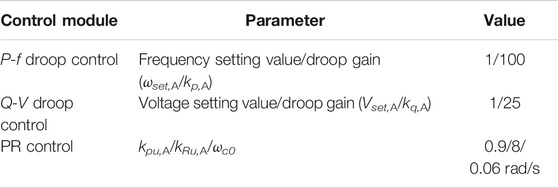
TABLE 1. Control parameters of the balance unit in the AC microgrid.
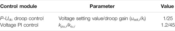
TABLE 2. Control parameters of the balance unit in the DC microgrid.
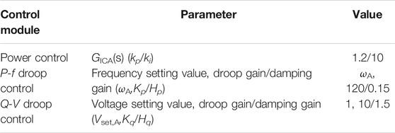
TABLE 3. Control parameters for DC-AC.
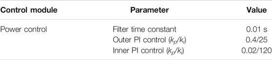
TABLE 4. Control parameters for DC-DC.
Simulation Verification
Based on the above simulation system, the proposed control method was verified under the following conditions. Case I: Energy storage period: In this case, the smooth start of power electronic interfaces in the multi-energy microgrid is first tested and verified, then the power disturbances and load fluctuations are simulated by online adjustment of the output power of the power units in the AC and DC microgrids to test the effectiveness of the proposed control strategy. Case II: Energy releasing period. In this case, the ice storage system should be put into operation first. Then, the equivalent loads of the remaining cooling loads and electric loads can be reasonably shared by balance units according to their rated capacity ratio. Case III: Fault of ICs. In this case, to validate the effectiveness of the established small signal model, we are assuming that the DC-AC faults.
Case I: Energy Storing Period
In the energy storing period, the dynamics of the power outputs of the power units, the common DC bus voltage, DC voltages, AC frequency, power outputs of the balance units in the AC/DC microgrids and the power outputs of the interlinking converters (ICs) are shown in Figures 4–7, respectively.
t < 0.4 s: The outputs of the power units in AC microgrid #A, DC microgrid #B and DC microgrid #C were Pp,A = 100 kW (1 in pu), Pp,B = 50 kW (0.5 in pu), and Pp,C = 20 kW (0.2 in pu), respectively, and all power electronic interfaces were in standby mode.
t = 0.4–3 s: DC-DC #B, DC-DC #C and DC-AC #A were put into operation at t = 0.4 s, 0.8 and 1.4 s, respectively. After the transient fluctuation, the common DC bus voltage, the voltage of the DC microgrids and the frequency of the AC microgrid can maintain stability, and all balance units shared power according to their rated capacity ratio (a:b:1 = 1:1:1).
t = 3–5 s: To simulate a power disturbance, at t = 3 s, the output of the power unit in the DC microgrid #C was changed to Pp,C = 50 kW (0.5 in pu); at t = 4 s, the outputs of the power units in AC microgrid #A and DC microgrid #B were changed to Pp,A = 50 kW (0.5 in pu) and Pp,B = 20 kW (0.2 in pu), respectively. After the transient fluctuation, the common DC bus voltage, the voltage of DC microgrids and the frequency of the AC microgrid can maintain stability, and all balance units shared all powers according to their rated capacity ratio (a:b:1 = 1:1:1).
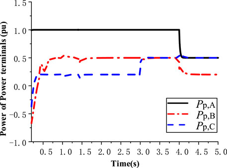
FIGURE 4. Dynamics of the power outputs of the power units.
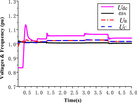
FIGURE 5. Dynamics of the voltage of the common DC bus, voltages of DC microgrids and frequency of AC microgrid.

FIGURE 6. Dynamics of the power outputs of the balance units.
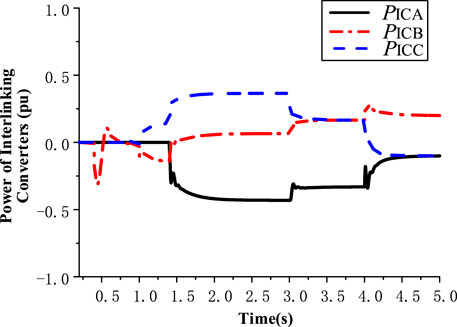
FIGURE 7. Dynamics of the power outputs of the ICs.
Case II: Energy Releasing Period
In this case, the ice storage system should be put into operation first. Then, the equivalent loads of the remaining cooling loads and electrical loads should be reasonably shared by the balance units according to their rated capacity ratio, dynamics of the common DC bus voltage, DC voltages, AC frequency, power outputs of balance units in AC/DC microgrids and power outputs of the ICs, as shown in Figures 8–10, respectively.
t < 6 s: The outputs of the power units in AC microgrid #A, DC microgrid #B and DC microgrid #C were Pp,A = −50 kW (−0.5 in pu), Pp,B = −50 kW (−0.5 in pu), and Pp,C = −50 kW (−0.5 in pu), respectively. The output of the balance unit (the energy conversion system) in AC microgrid #A was Ps,A = 50 kW (0.5 in pu), and all power electronic interfaces have been put into operation and reached steady state.
t = 6–8 s: At t = 6 s, assuming that the equivalent cooling load is 100 kW, and the other electric loads are 100 kW, the ice storage device (the equivalent balance unit) in AC microgrid #A was put into operation first to bear part of the cooling load (50 kW). The remaining equivalent cooling load and the other electric loads (150 kW) were automatically shared by the balance units of DC microgrid #B and DC microgrid #C according to their rated capacity ratio (b:1 = 1:1), and the common DC bus voltage, the voltage of DC microgrids and the frequency of the AC microgrid can maintain stability, which verified the effectiveness of the proposed control method.
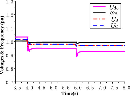
FIGURE 8. Dynamics of the voltage of the common DC bus, voltage of DC microgrids and frequency of AC microgrid.
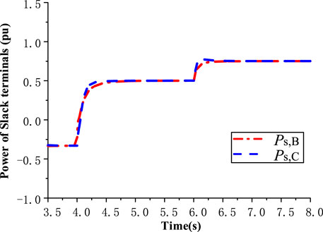
FIGURE 9. Dynamics of the power outputs of the balance units.
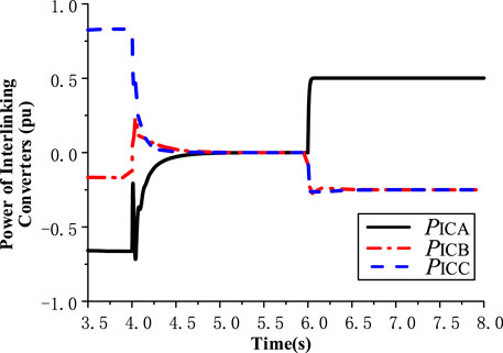
FIGURE 10. Dynamics of the power outputs of the ICs.
Case III: Fault of Interlinking Converters
In this section, to validate the effectiveness of the proposed method, we are assuming that the DC-AC faults, as an example, at t = 3 s. The dynamics of the power outputs of the power units, the common DC bus voltage, the DC voltages, the AC frequency, the power outputs of the balance units in AC/DC microgrids and the power outputs of the ICs are shown in Figures 11–14, respectively.
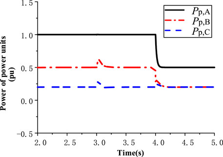
FIGURE 11. Dynamics of the power outputs of the power units.
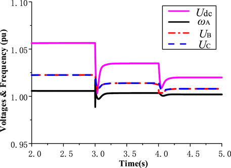
FIGURE 12. Dynamics of the voltage of the common DC bus, voltages of DC microgrids and frequency of AC microgrid.
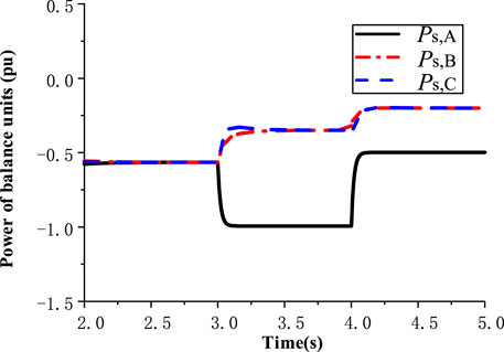
FIGURE 13. Dynamics of the power outputs of the balance units.
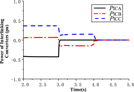
FIGURE 14. Dynamics of the power outputs of the ICs.
Conclusion
In this paper, an autonomous cooperative control strategy for multi-energy microgrids is proposed, which is suitable for considering ice storage systems and comprehensive utilization of energy. On the premise of using the ice storage system as a priority, all loads can be reasonably shared by all balance units, which improves the utilization efficiency of the balance units. In addition, the complete small signal model of the system is constructed, which can also be used to analyze the features and characteristics of the system and guide the optimized design of the control parameters. The simulation results verify the effectiveness of the proposed control method.
Data Availability Statement
The original contributions presented in the study are included in the article/Supplementary Materials, further inquiries can be directed to the corresponding author.
Author Contributions
ZD is responsible for the design and thinking of the project, CS and WH is responsible for the model design and paper writing, GM and ZL is responsible for providing part of the data, WJ and HY is responsible for the collation and collection of the data.
Funding
The work was supported in part by Key Research and Development Program of Zhejiang Province under Grant 2019C01149, in part by State Grid Corporation Science and Technology Project under Grant 5211DS180031, in part by National Natural Science Foundation of China under Grant 61903333, in part by Zhejiang Provincial Natural Science Foundation of China under Grant LQ19F030008.
Conflict of Interest
HW, MG, and LZ were employed by the company State Grid Huzhou Power Supply Company. JW and YH were employed by the company Huzhou Xinlun Comprehensive Energy Service Co., Ltd.
The remaining authors declare that the research was conducted in the absence of any commercial or financial relationships that could be construed as a potential conflict of interest.
Publisher’s Note
All claims expressed in this article are solely those of the authors and do not necessarily represent those of their affiliated organizations, or those of the publisher, the editors and the reviewers. Any product that may be evaluated in this article, or claim that may be made by its manufacturer, is not guaranteed or endorsed by the publisher.
Supplementary Material
The Supplementary Material for this article can be found online at: https://www.frontiersin.org/articles/10.3389/fenrg.2021.692026/full#supplementary-material
References
Alegria, E., Brown, T., Minear, E., and Lasseter, R. H. (2014). CERTS Microgrid Demonstration with Large-Scale Energy Storage and Renewable Generation. IEEE Trans. Smart Grid 5 (2), 937–943. doi:10.1109/tsg.2013.2286575
Bouzid, A. M., Guerrero, J. M., Cheriti, A., Bouhamida, M., Sicard, P., and Benghanem, M. A survey on control of electric power distributed generation systems for microgrid applications. Renew. Sust. Energ. Rev., vol. pp. 44: 751–766. 2015. doi:10.1016/j.rser.2015.01.016
Ouammi, A., Dagdougui, H., Dessaint, L., and Sacile, R. . “Coordinated Model Predictive-Based Power Flows Control in a Cooperative Network of Smart Microgrids”. IEEE Trans. Smart Grid, vol. no. 6, pp. 2233–2244. 2015. doi:10.1109/tsg.2015.2396294
Cheng, F., Qu, L., Qiao, W., Wei, C., and Hao, L. (2019). Fault Diagnosis of Wind Turbine Gearboxes Based on DFIG Stator Current Envelope Analysis. IEEE Trans. Sustain. Energ. 10 (3), 1044–1053. doi:10.1109/tste.2018.2859764
Ding, Q., Duan, S., Wang, Z., Sun, G., and Wang, J. (2014). Economy of Ice-storage Air-condition Used in the Area of High Peak-valley Load Difference. Proc. CSU-EPSA 80 (1), 72–75.
Ge, W., Li, Z., Xie, H., Li, Y., and Yuan, C. (2017). Research on Optimal Coordinated Operation for Micro-grid with Energy Storage and Ice Storage System. Distribution & Utilization 34 (07), 28–33.
Gupta, A., Doolla, S., and Chatterjee, K. (2018). Hybrid AC-DC Microgrid: Systematic Evaluation of Control Strategies. IEEE Trans. Smart Grid 9 (4), 3830–3843. doi:10.1109/tsg.2017.2727344
Huang, X., Wang, K., Qiu, J., Hang, L., Li, G., and Wang, X. (2019). Decentralized Control of Multi-Parallel Grid-Forming DGs in Islanded Microgrids for Enhanced Transient Performance. IEEE Access 7, 17958–17968. doi:10.1109/access.2019.2896594
Jena, S., and Padhy, N. P. (2020). Distributed Cooperative Control for Autonomous Hybrid AC/DC Microgrid Clusters Interconnected Via Back-To-Back Converter Control. IEEE Power Energ. Soc. Gen. Meet., 1–5.
Jia, L., Zhu, Y., Du, S., and Wang, Y. (2018). Analysis of the Transition Between Multiple Operational Modes for Hybrid AC/DC Microgrids. Csee Jpes 4 (1), 49–57. doi:10.17775/cseejpes.2016.01030
Kerdphol, T., Rahman, F. S., Mitani, Y., Watanabe, M., and Kufeoglu, S. (2018). Robust Virtual Inertia Control of an Islanded Microgrid Considering High Penetration of Renewable Energy. IEEE Access 6, 625–636. doi:10.1109/access.2017.2773486
Lai, J., Lu, X., Yu, X., and Monti, A. (2019). Cluster-Oriented Distributed Cooperative Control for Multiple AC Microgrids. IEEE Trans. Ind. Inf. 15 (11), 5906–5918. doi:10.1109/tii.2019.2908666
Liu, X., Wang, P., and Loh, P. C. (2011). A Hybrid AC/DC Microgrid and its Coordination Control. IEEE Trans. Smart Grid 2 (2), 278–286.
Loh, P. C., Li, D., Chai, Y. K., and Blaabjerg, F. (2013). Autonomous Control of Interlinking Converter with Energy Storage in Hybrid AC-DC Microgrid. IEEE Trans. Ind. Applicat. 49 (3), 1374–1382. doi:10.1109/tia.2013.2252319
Loh, P. C., Li, D., Chai, Y. K., and Blaabjerg, F. (2013). Autonomous Operation of Hybrid Microgrid with AC and DC Subgrids. IEEE Trans. Power Electron. 28 (5), 2214–2223. doi:10.1109/tpel.2012.2214792
Lu, Z., Wang, C., Min, Y., Zhou, S., and Lv, J. (2007). Overview on Microgrid Research. Automation Electric Power Syst. 31 (19), 100–107.
He, M., and Giesselmann, M. (2015). “Reliability-Constrained Self-Organization and Energy Management towards a Resilient Microgrid Cluster”. IEEE Power & Energy Society Innovative Smart Grid Technologies Conference, Washington, DC, United States (IEEE), 1–5.
Parhizi, S., Lotfi, H., Khodaei, A., and Bahramirad, S. (2015). State of the Art in Research on Microgrids: a Review. IEEE Access 3, 890–925. doi:10.1109/access.2015.2443119
Pashajavid, E., Shahnia, F., and Ghosh, A. (2017). Provisional Internal and External Power Exchange to Support Remote Sustainable Microgrids in the Course of Power Deficiency. IET Generation, Transm. Distribution 11 (1), 246–260. doi:10.1049/iet-gtd.2016.0897
Peyghami, S., Mokhtari, H., and Blaabjerg, F. (2018). Autonomous Operation of a Hybrid AC/DC Microgrid with Multiple Interlinking Converters. IEEE Trans. Smart Grid 9 (6), 6480–6488. doi:10.1109/tsg.2017.2713941
Su, X., Bai, X., Liu, C., Zhu, R., and Wei, C. (2019). Research on Robust Stochastic Dynamic Economic Dispatch Model Considering the Uncertainty of Wind Power. IEEE Access 7, 147453–147461. doi:10.1109/access.2019.2946460
Sun, F., Ma, J., Yu, M., and Wei, W. (2019). “A Robust Optimal Coordinated Droop Control Method for Multiple VSCs in AC-DC Distribution Network”,” in IEEE Transactions on Power Systems, Early Access (New Jersey, United States: IEEE).
Unamuno, E., and Barrena, J. A. (2015). Hybrid AC/DC Microgrids-Part I: Review and Classification of Topologies. Renew. Sust. Energ. Rev. 52, 1251–1259. doi:10.1016/j.rser.2015.07.194
Wang, C. (2013). Analysis and Simulation Theory of Microgrid. Beijing: Science Press. doi:10.1190/nsgapc2013-084
Wang, C., Liu, Y., Li, X., Guo, L., Qiao, L., and Lu, H. (2016). Energy Management System for Stand-Alone Diesel-Wind-Biomass Microgrid with Energy Storage System. Energy 97, 90–104. doi:10.1016/j.energy.2015.12.099
Wei, C., Bai, X., and Kim, T. (2019a). A Survey on Optimal Control and Operation of Integrated Energy Systems. Complexity, 1076–2787.
Wei, C., Benosman, M., and Kim, T. (2019b). Online Parameter Identification for State of Power Prediction of Lithium-Ion Batteries in Electric Vehicles Using Extremum Seeking. Int. J. Control. Autom. Syst. 17 (11), 2906–2916. doi:10.1007/s12555-018-0506-y
Wei, C., Shen, Z., Xiao, D., Wang, L., Bai, X., and Chen, H. (2021). An Optimal Scheduling Strategy for Peer-To-Peer Trading in Interconnected Microgrids Based on RO and Nash Bargaining. Appl. Ener. 275.
Xia, Y., Wei, W., Yu, M., Peng, Y., and Tang, J. (2018). Decentralized Multi-Time Scale Power Control for a Hybrid AC/DC Microgrid with Multiple Subgrids. IEEE Trans. Power Electron. 33 (5), 4061–4072. doi:10.1109/tpel.2017.2721102
Xia, Y., Wei, W., Yu, M., Wang, X., and Peng, Y. (2018). Power Management for a Hybrid AC/DC Microgrid with Multiple Subgrids. IEEE Trans. Power Electron. 33 (4), 3520–3533. doi:10.1109/tpel.2017.2705133
Yan, H., Shi, K., Xu, G., Li, D., and Lin, S. (2016). Research on Control Strategy of Dynamic Ice Storage System Based on Economic Optimization. Control Eng. China 23 (2), 303–308.
Yang, L., Tai, N., and Fan, C. (2017). Regulation and Stabilization by Ice Storage Air-Conditioning and Battery Energy Storage System in Microgrids. IEEJ Trans. Elec Electron. Eng. 12 (2), 176–184. doi:10.1002/tee.22364
Yang, P., Xia, Y., Yu, M., Wei, W., and Peng, Y. (2018). A Decentralized Coordination Control Method for Parallel Bidirectional Power Converters in a Hybrid AC-DC Microgrid. IEEE Trans. Ind. Electron. 65 (8), 6217–6228. doi:10.1109/tie.2017.2786200
Yang, X., Su, J., Lv, Z., Liu, H., and Li, R. (2014). Overview on Micro-grid Technology. Proc. CSEE” 1, 57–70.
Keywords: hybrid AC/DC microgrids, autonomous cooperative control, multi-energy complementarity, energy storage systems, small signal mode
Citation: Zhou D, Chen S, Wang H, Guan M, Zhou L, Wu J and Hu Y (2021) Autonomous Cooperative Control for Hybrid AC/DC Microgrids Considering Multi-Energy Complementarity. Front. Energy Res. 9:692026. doi: 10.3389/fenrg.2021.692026
Received: 07 April 2021; Accepted: 12 July 2021;
Published: 03 August 2021.
Edited by:
Xingang Fu, Texas A&M University Kingsville, United StatesReviewed by:
Rui Wang, Northeastern University, ChinaDazhong Ma, Northeastern University, China
Taesic Kim, Texas A&M University Kingsville, United States
Copyright © 2021 Zhou, Chen, Wang, Guan, Zhou, Wu and Hu. This is an open-access article distributed under the terms of the Creative Commons Attribution License (CC BY). The use, distribution or reproduction in other forums is permitted, provided the original author(s) and the copyright owner(s) are credited and that the original publication in this journal is cited, in accordance with accepted academic practice. No use, distribution or reproduction is permitted which does not comply with these terms.
*Correspondence: Dan Zhou, zhoudan@zjut.edu.cn