Quantum Control of Coherent π-Electron Dynamics in Aromatic Ring Molecules
 Hirobumi Mineo
 Ngoc-Loan Phan3
 - 1Atomic Molecular and Optical Physics Research Group, Advanced Institute of Materials Science, Ton Duc Thang University, Ho Chi Minh City, Vietnam
- 2Faculty of Applied Sciences, Ton Duc Thang University, Ho Chi Minh City, Vietnam
- 3Department of Physics, Ho Chi Minh City University of Education, Ho Chi Minh City, Vietnam
- 4Department of Chemistry, Graduate School of Science, Tohoku University, Sendai, Japan
Herein we review a theoretical study of unidirectional π-electron rotation in aromatic ring molecules, which originates from two quasi-degenerate electronic excited states created coherently by a linearly polarized ultraviolet/visible laser with a properly designed photon polarization direction. Analytical expressions for coherent π-electron angular momentum, ring current and ring current-induced magnetic field are derived in the quantum chemical molecular orbital (MO) theory. The time evolution of the angular momentum and the ring current are expressed using the density matrix method under Markov approximation or by solving the time-dependent Schrödinger equation. In this review we present the results of the following quantum control scenarios after a fundamental theoretical description of coherent angular momentum, ring current and magnetic field: first, two-dimensional coherent π-electron dynamics in a non-planar (P)-2,2’-biphenol molecule; second, localization of the coherent π-electron ring current to a designated benzene ring in polycyclic aromatic hydrocarbons; third, unidirectional π-electron rotations in low-symmetry aromatic ring molecules based on the dynamic Stark shift of two relevant excited states that form a degenerate state using the non-resonant ultraviolet lasers. The magnetic fields induced by the coherent π-electron ring currents are also estimated, and the position dependence of the magnetic fluxes is demonstrated.
1 Introduction
Recent progress in laser science and technology has facilitated the coherent control of ultrafast charge migration dynamics in molecular systems [1–21]. Controlled charge migration can generate unidirectional currents and current-induced magnetic fields, which can be used as a guiding principle for the next-generation ultrafast optoelectronic devices [22, 23]. Laser control of π-electron rotations in aromatic ring molecules is a typical example. Pioneering studies on the generation of coherent π-electron rotations in high-symmetry ring molecules such as Mg porphyrin having degenerate excited states have been reported by the Manz group [24–26]. π-Electron rotations were induced by degenerate electronic excited states, which were coherently created by circularly polarized ultraviolet (UV) lasers. The generation mechanism of the photon angular momentum involves the photon transfer from the circularly polarized UV lasers to the π-electrons, thereby the left- or right-handed circular polarization of the applied laser defines the rotational direction of the angular momentum [27]. In contrast in ring molecules with low-symmetry π-electrons cannot be rotated by using the circularly polarized lasers, due to the absence of electronic excited states degenerate, that would receive the photon angular momentum. Thus, it was commonly understood that coherent π-electron rotations could not be generated in low-symmetry aromatic ring molecules. However, Kanno et al. [28–31] have invalidated this long-established understanding by demonstrating that π-electrons in oriented chiral aromatic ring molecules can be rotated by the coherent excitation of a pair of quasi-degenerate π-electronic excited states using a linearly polarized UV/vis laser pulse with a properly designed photon polarization direction [28, 29]; the polarization direction of the pulse determines the initial direction of the π-electron rotation, whether right- or left-handed one. The duration of the unidirectional rotation is inversely proportional to the energy difference between the two quasi-degenerate excited states, and inverse rotation begins after the duration because the coherent state is not a nonstationary state rather than an eigenstate. Pump and dump laser pulses with their properly designed polarization directions for these lasers are applied to eliminate the reverse rotation. The number of unidirectional rotations during the duration can be estimated from the energy difference between the quasi-degenerate excited and ground states. This only applies to the ideal case in which any dephasing processes disturbing the electronic coherence are omitted. It is expected that unidirectional ring currents produce much stronger magnetic fields than traditional static magnetic fields [32, 33].
The concept of the conventional ring current has already been established previously and plays an important role in interpreting the magnetic properties and aromaticity of conjugated molecular systems [34, 35]. The molecules investigated based on the ring current are in the ground state, and the current densities for evaluation of the ring current are calculated using the first-order electronic wave function in the time-independent magnetic field and in a permanent magnetic dipole. Such a conventional ring current should be called an incoherent current.
In this article, we present the most recent results of our theoretical studies on the quantum control of coherent π˗electron rotations in low-symmetry aromatic ring molecules. Low-symmetry aromatic ring molecules are not rare, but rather common: high-symmetry aromatic molecules often become low-symmetry ones by substitution of a functional group, or under environment conditions. In the next section, the fundamental theory for the quantitative analysis of coherent π-electrons in a low-symmetry aromatic ring molecule is introduced. Here, the time-dependent coherent angular momentum, ring current, and ring current-induced magnetic field are analytically derived in a closed form in the quantum chemical MO theory. Time-evolutions of these quantities are derived by the density matrix method [36–39]. The temporal behavior of coherence is determined by the off-diagonal element of density matrix. Then, the Markov approximation is ultilized for considering the dephasing effects on the conherent angular momenta and ring currents. The magnitudes of the electronic angular momenta and ring currents are expressed as the summation of the expectation values of the corresponding one-electron operators in the aromatic rings. The bond current between the nearest neighbor carbon atoms, Ci and Cj, is defined as an electric current flowing through a half plane perpendicular to the Ci
2 Coherent π-electron Dynamics in Low-Symmetry Aromatic Ring Molecules
In this section we present the theoretical formalism for the coherent π-electrons in a low-symmetry aromatic ring molecule to derive analytical expressions for the coherent angular momentum, ring current and the current-induced magnetic field within the framework of the quantum chemical MO treatment [39, 40].
2.1 Equations of Motion for Coherent π-Electron Rotations Induced by Ultrashort UV/Vis Lasers
The expectation values of the coherent π−electron angular momentum and the ring current operators in an aromatic molecule are generally expressed as
Here,
where
The coherent and incoherent temporal behaviors of the electrons induced by a laser field
Here,
Because we are interested in the coherent behaviors of dipole-allowed quasi-degenerate π-electronic excited states in the visible or UV region of an aromatic ring molecule, Eq. 1 can be rewritten in terms of singly excited configurations
where
In Eq. 4, the coherence between singly excited state configurations is considered, and the coherence between the ground state and the excited state is neglected because this coherence is much shorter compared to that between the singly excited state configurations. In this case, the coherence time is proportional to the inverse of the energy gap between the two electronic states.
The coherent π-electron angular momentum is formulated in the quantum chemical MO theory, and the π-orbital
where
Equation 4 can be expressed by using the Eq. 5 as
Here, the temporal behavior of the expectation value
2.2 Coherent π-Electron Angular Momentum
Consider the spatially fixed aromatic ring molecule with N aromatic rings. The electron angular momentum operator is defined as
where ne is the total number of electrons in the system.
Note that in Eq. 7 the dependence of the electron angular momentum on the laser intensity is reflected in the imaginary part of the off-diagonal density matrices
2.3 Coherent π-Electron Ring Current
From Eq. 6, the perpendicular component of the time-dependent electric current flowing through a surface S (SeeFigure 1) is generally defined as
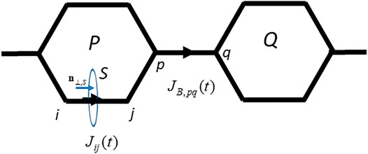
FIGURE 1. The interatomic bond current
Here
Equation 8 can be expressed as
where
with
where
We introduce the bridge bond current
The bridge bond current is given in terms of the interatomic current,
Here,
We now define an averaged ring current along ring K,
where
2.4 Application to Nonplanar (P)-2,2’-biphenol
(P)-2,2’-biphenol is one of the typical nonplanar chiral aromatic ring molecules, which has two aromatic rings connected through the C-C bridge bond. For convenience, hereafter, we denote L (R) for the left- (right-) hand side phenol ring of (P)-2,2’-biphenol. Figure 2A exhibits the geometrical structure of (P)-2,2’-biphenol with the transition dipole moments vectors between the ground and excited states. (P)-2,2’-biphenol was assumed to be fixed on a surface by a non-conjugated chemical bond or was oriented in the space by the molecular orientation techniques by laser [44–46]. The laboratory-fixed Y-axis was set parallel to the single chemical bond bridging two phenol molecules, and the rotational axis of the molecule belonging to point group C2 was set along the laboratory-fixed Z-axis which was parallel to the surface normal. The ground state geometry of (P)-2,2’-biphenol was optimized using the DFT-B3LYP level theory with the 6-31G+(d,p) basis set in the GAUSSIAN09 code [47]. The dihedral angle
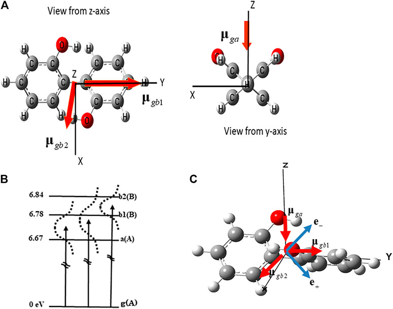
FIGURE 2. (A) Geometrical structure of (P)-2,2’-biphenol belonging to point group C2 and the transition dipole moments between the ground state (g) and three excited states a, b1 and b2. (B) Three electronic excited states and the dipole allowed transitions used to create the coherent electronic states. A and B are the irreducible representations of point group C2. Dotted lines indicate the laser band widths that cover the superpositions of two electronic excited states (a b1), (a b2) and (b1 b2) respectively. (C) Linearly polarized unit vector of laser e+ (e−) used to generate the in-phase superposition (a+b1) (out-of-phase superposition (a-b1)).
To create the coherent angular momenta and ring currents in (P)-2,2’-biphenol, we focused on the three dipole-allowed electronic excited states (a, b1, and b2) as shown in Figure 2B. The transition energies from the ground (g) to the a, b1, and b2 states, which were calculated under the optimized ground state geometry using the TD-DFT B3LYP level of theory [39, 40] were 6.67, 6.78, and 6.84 eV, respectively.
2.4.1 Generation of Two-state Electronic Coherence Using Linearly Polarized UV Pulses
For a creation of the coherent angular momentum and ring current using linearly polarized laser pulses, it is essential to prepare for an electronic coherence with a fixed relative phase between two electronic states, a and b1, i.e., in-phase (a + b1) or out-of-phase (a - b1). The principle behind the preparation of the electronic coherence (a + b1) ((a − b1)) using a linearly polarized laser with polarization unit vector e+ (e-) is schematically demonstrated in Figure 2C [39, 40].
In the frame work of the three-excited state model, there are three types of two-electronic coherent states represented as
It is remarkable that even though the third excited state is located between the two excited states in the three-excited states system, the coherent electronic state can still be created if the applied linearly polarized lasers satisfy the following conditions. For example, for the (a ± b2) electronic coherence, the conditions for the linearly polarized lasers with polarization vectors
or equivalently,
Thus, if the laser overlaps the electronic states a, b1, and b2, the (a + b2) or (a – b2) electronic coherent state can be created selectively.
2.4.2 Coherent Angular Momentum Quantum Beats and Bond Currents
Figure 3 exhibits the temporal behaviors of the angular momenta calculated for three types of electronic coherences, (b1+b2), (a + b1) and (a + b2), each of which is created by a linearly polarized UV laser pulse with a properly selected polarization direction of laser. For the (b1+b2) electronic coherence, the total angular momentum parallel to the Z-axis, lZ, is created together with two ring components lL = lR, whereas for both the (a + b1) and (a + b2) electronic coherences, the total angular momenta parallel to the X-axis, lX, are generated with lL =
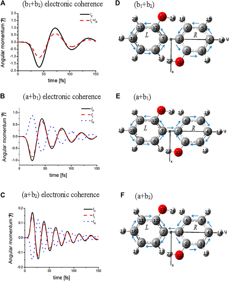
FIGURE 3. Temporal behaviors of the coherent angular momenta, total values lZ (lX), and components, lL (lR) of L (R) ring for three types of the electronic coherence and the directions of the bond currents at the initial time: upper panel for (b1 + b2) electronic coherence excited by laser pulse with amplitude of 0.19 TW/cm2; middle panel for (a + b1) electronic coherence excited by laser pulse with amplitude of 0.83 TW/cm2; lower panel for (a + b2) electronic coherence excited by the laser pulse with amplitude of 3.32 TW/cm2. The dephasing constants were set as γb1b2 = γab1= γab2 = 0.01 eV (∼1/50 fs −1). The arrows above the C – C bonds indicate the initial directions of the currents. Note that the bridge bond current J1,7 = 0 for the (b1 +b2) electronic coherence, while J1,7
The angular momenta
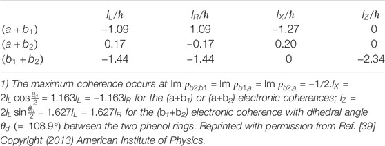
TABLE 1. Angular momenta of the two phenol rings
The magnitudes of the bond current,
Effects of dephasings on coherent π-electron angular momentum and ring currents were treated in the Markov approximation, and time-independent dephasing constants were used under the assumption of instantaneous interactions between the system and phonon baths. In a system such as condensed phases, the Markov approximation is broken down. Non-Markov response of coherent should be essential. Time evolution of coherent ring currents were calculated in a hierarchical master equation approach beyond the Markov approximation has been treated [49].
2.4.3 Ultrafast Quantum Switching of Angular Momentum
Consider the quantum control of
Figure 4A presents a 3D plot of the angular momentum as it switches based on the sequential four-step control scheme. From Figure 4A, we can see that the
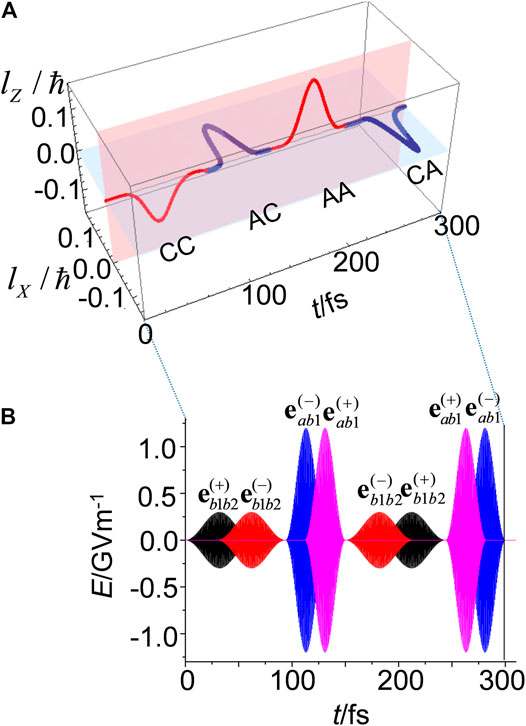
FIGURE 4. (A) Sequential four-step quantum switching of
The pulses shown in Figure 4B have two features. The first feature is that the pump (dump) pulse for each step has polarizations,
With respect to ultrafast quantum switching, it is crucial to create the overlap of the pump and dump pulses, where the resulting electric field rotates as an elliptically polarized electric field in the overlapped time domain, and the dump laser pulse reverse the rotation that occurs during this region. As a result, the angular momentum of the
2.4.4 Coherent Ring Current-Induced Magnetic Field
There have been interesting reports on the evaluation of the magnetic fields of atoms and oriented heteronuclear diatomic molecules, AlCl and BeO [32, 50, 51]. Strong and unidirectional magnetic fields are generated from the degenerate electronic states of these atoms and molecules excited by circularly polarized intense laser pulses. We estimated the magnetic fields (magnetic field flux density) generated by the coherent ring currents of (P)-2,2’-biphenol. The results may provide fundamental information for designing ultrafast switching devices controlled by current-induced magnetic fields as well as coherent ring currents [52–54].
As an example, consider the magnetic field induced by the ring current for the (b1 + b2) electronic coherence. In Figure 5,
which was derived using a simple ring loop (SRL) model. Here,
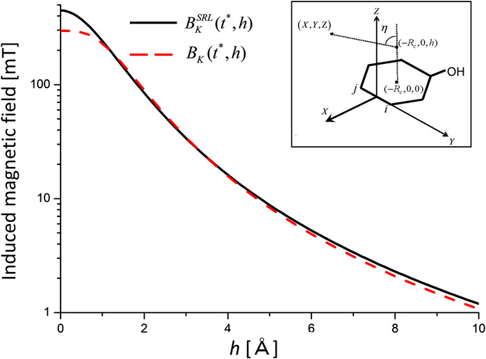
FIGURE 5. Induced magnetic fields for the (b1 +b2) electronic coherence as a function of height h measured from the center of aromatic ring K at the maximum coherence time
It is necessary to check whether the value of
Thus far, we have taken into account the ring current-induced magnetic fields of the low-symmetry aromatic ring molecule (P)-2,2’-biphenol, in which nondegenerate two electronic excited states are coherently excited by the linearly polarized UV lasers. Here we briefly discuss the ring current-induced magnetic field for the degenerate electronic excited states of an aromatic molecule induced by the intense circularly polarized UV laser pulse. Yuan and Bandrauk [2, 33] have numerically demonstrated that the circularly polarized ultrashort pulses are generated from the molecular high-order harmonic generation using the intense linearly and circularly polarized laser pulses. This indicates a possibility for the ultrashort circularly polarized UV laser pulses to create the ring current-induced magnetic fields in high symmetric aromatic ring molecules. We can estimate the magnitude of the ring current-induced magnetic field of benzene within the SRL model using Eq. 15. Here,
3 Current Localization in Polycyclic Aromatic Hydrocarbons
In this section we consider a localization of coherent ring current in polyatomic aromatic hydrocarbons (PAH) [41, 42]. There exist various current localization patterns in PAH simply because of their geometrical structures consisting of many benzene units. Quantum optimal control method is a general and reliable one to choose a desired current localization pattern from the various patterns using control lasers. The quantum control method has successfully been applied to manipulation of molecules such as coherent control of chemical reactions [56, 57]. After a brief introduction of quantum optimal control method [41, 42, 58], we demonstrate how the target state is set up for the designated ring current using the Lagrange multiplier method. Here, the π-electron ring current is expressed in terms of the interatomic bond currents between two adjoining C–C atoms. At final, the target states are derived for the two types of current localization: the localized ring current, which indicates that the ring current is localized to the designated aromatic ring in linear PAH, and the perimeter ring current in linear PAH [41, 42].
3.1 Quantum Optimal Control Approach
The objective functional to be maximized, is defined as [59–61].
where
where
Here,
3.2 Setup of Target Operators
Consider the ring current localization to a designated ring
with
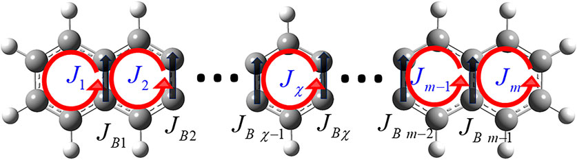
FIGURE 6. π-Electron ring currents
Here, n is the number of electronic excited states. Hereafter, we write
The target state
The coupled equations for the ring current localization to aromatic ring
and
A brief derivation of Eq. 19 is summarized in Appendix A.
The coefficients
Now consider the bridge bond currents
and
respectively.
Similar to Eq. 19, the coupled equations for the perimeter ring current are derived in Appendix B.
3.3 Application of Current Localization Control to Anthracene
We applied the quantum optimal control (QOC) method described in the preceding section to anthracene, one of the smallest PAHs [42]. Anthracene (D2h) was assumed to be fixed on a surface (the XY plane), or oriented spatially by lasers The molecular geometry was optimized in the MP2/6-311+g(d,p) level theory using the GAUSSIAN09 code [47]. As demonstrated in Figure 7A, anthracene consists of three aromatic rings, which are called L-, M-, and R- rings respectively.
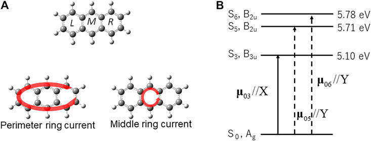
FIGURE 7. (A) Symmetry-adapted ring currents (B1g) in anthracene, perimeter ring current, and middle ring current. (B) The electronic excited states adapted for laser control of π-electron ring in anthracene (D2h), and the non-zero transition dipole moments between the ground/excited-excited states. The solid (dashed) arrows represent the transition dipole moments which are parallel to the X (Y) axis.
Consider the two types of π-electron localized ring currents of anthracene: the perimeter current flowing along the outside chemical bonds of anthracene, and the middle ring current localized to the M-ring. Both types of localized ring currents belong to the irreducible representation B1g of the D2h point group, which are symmetry-adapted. The excited states contributing to the two ring currents need to belong to the B3u and B2u representations, because each corresponding electronic coherence created by the two excited states belongs to the B1g representation. The excited state for the localized ring current is S3 with B3u representation, and the other two excited states S5 and S6 with B2u representation as shown in Figure 7B. This defines a “symmetry-adapted ring current” [41, 42].
The excited state energies in Figure 7B were calculated to be
Figure 8 shows the QOC results for the generation of an anti-clockwise perimeter ring current in anthracene. The target state is expressed from the results obtained using the Lagrange multiplier method as
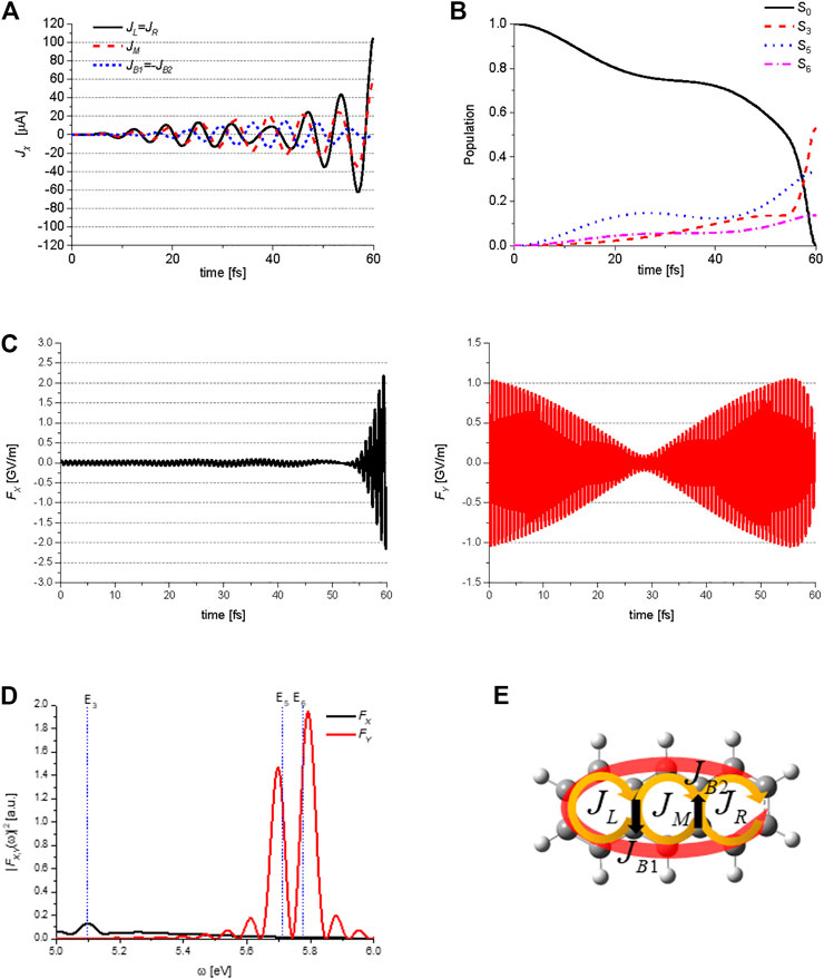
FIGURE 8. Quantum optimal control simulations for generation of the perimeter ring current in anthracene: (A) temporal behavior of the three ring currents
Here, the subscripts specifying the target state, for example, ACA for
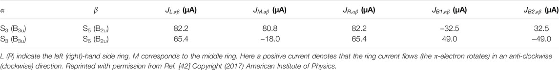
TABLE 2. Matrix elements of the coherent π-electron ring currents for the three aromatic rings of anthracene,
Figure 8B shows the temporal behavior of the ground state S0, and three excited states S3 (B3u), S5 (B2u), and S6 (B2u) populations during the QOC process, which are induced by the two control lasers. Figure 8C shows the X and Y-components of the electric field
Thus far, we have considered the QOC procedure for generating an anti-clockwise perimeter current. The QOC procedure for generating a clockwise perimeter current can be carried out in the same manner as described above (SeeEq. 21) by considering the target state,
We carry out the QOC procedure to generate the anticlockwise ring current localized to the middle ring of anthracene. The target state is expressed as
The target state for the middle ring current with the clockwise flow is given by the relationship
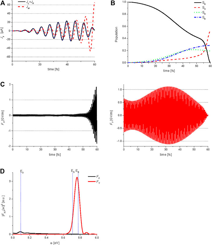
FIGURE 9. Quantum optimal control simulations for generation of the middle ring current in anthracene: (A) temporal behavior of the ring currents
Main difference between the temporal behaviors of the Y-polarized lasers in Figure 8C and Figure 9C can be explained briefly in the following. The two coherent states created by the Y-polarized lasers can be expressed as
and
For simplicity, the amplitudes of the two coherent states are assumed to have the same value, i.e.,
and
Here, the frequency difference
Having clarified the control mechanism of the coherent ring current generation, we can semi-quantitatively reproduce the above results in Figures 8, 9 by using an analytical method [42]. This indicates, in principle, that two types of ring current localizations, the perimeter ring current and the middle ring current in linear PAHs, can be generated in experiment using three coherent UV lasers without a sophisticated QOC device.
For QOC numerical simulations of the ring current localization control in anthracene, we have only considered the perimeter and the middle ring currents generations, which are symmetry-adapted, while we did not consider a ring current localization to the L- or R-ring of anthracene, which are created by a symmetry-broken procedure, as demonstrated for naphthalene in Ref. [41]. That is, other excited state(s) with gerade symmetry must be considered in addition to the excited states with ungerade symmetry as described in the previous subsection.
It is important to consider how to observe the ultrafast coherent ring currents in PAHs. We proposed a method to detect the direction of the atto-second coherent ring current by tracking the femtosecond molecular vibrational motions that can induce the nonadiabatic couplings [30]. Rodriguez and Mukamel [63] have proposed measuring the circular dichroism (CD) of the ring current using the pump-probe method. Recently, two methods have been proposed for the detection of the ultrafast coherent ring currents. One method, recently proposed by Yuan et al., Bandrauk’s group [64], is utilizing the atto-second detection method of the coherent electronic dynamics in molecules with the temporal and spatial resolutions using the circularly polarized ultrashort UV pump and X-ray probe laser pulses. The other method is to utilize the time-resolved scanning microscopy (STM) and the magnetic force microscopy (MFM) to detect the ring current-induced magnetic fields during the ultrashort time [65–67].
It is also expected that to apply our methods to planar or non-planar extended molecular systems, such as graphene sheets. In principle, our method can be extended to these large systems, by considering the symmetry of the molecular system and the constraints on the π-electron ring currents.
Using laser control, it is also essential to maintain the created ring current at the target region (path) at least during one vibrational period of the PAH [68]. Otherwise, the created ring current would dissipate quickly because of the vibronic interactions and/or the nonadiabatic couplings between the two electronic excited states [30, 69–71].
4 Dynamic Stark-Induced π-Electron Rotations in Low-Symmetry Aromatic Ring Molecules
In this section, we present a convenient method for inducing unidirectional π-electron rotations in aromatic ring molecules with low symmetry [43]. The basic idea behind the induction of unidirectional electron rotations is to degenerate two nondegenerate excited states by utilizing dynamic Stark shifts, as demonstrated in Figure 10. We refer to this as the dynamic Stark-induced degenerate electronic state (DSIDES) [43]. Two linearly polarized continuous lasers operating at different frequencies and phases are used to form DSIDES: Each laser is set to selectively interact with each electronic state through non-resonant excitation. The lower and higher excited states are shifted up and down with the same population, respectively, and the DSIDES is formed at the center between them. As a result, unidirectional π-electron rotation is driven by two lasers. In the laser control scenario, only one input parameter out of the four possible parameters (frequency and intensity for each laser), is required to induce the DSIDES formation.
FIGURE 10. Dynamic Stark-induced degenerate state with the Rabi frequencies (Ω1 and Ω2) using two stationary linearly-polarized lasers with the frequencies,
First, the DSIDES formation is described in a three-electronic state model under the fixed nuclei condition, and the time-dependent expectation value of the angular momentum operator of π-electrons is derived and analytically expressed. Next, to demonstrate the applicability of the control scenario, the results of the DSIDES treatment for toluene, which is a typical aromatic ring molecule of low symmetry belonging to Cs point group, are presented.
4.1 Formation of Dynamic Stark-Induced Degenerate Electronic State DSIDES and the Resulting Angular Momentum
Consider the coherent π-electron angular momentum in an aromatic ring molecule with low symmetry excited by non-resonant, stationary UV/visible lasers. The molecule of our interest is one oriented in a space or attached to a surface, as mentioned in the preceding sections. We adopt a three-electronic state model in the frozen nuclei approximation. The three electronic states including the ground state specified by the energy
Here, the normalization condition for the coefficients
The system Hamiltonian interacting with the electric fields is given as
where
Here
The time-dependent Schrödinger equation can be written as
The coefficients must satisfy the coupled differential equation
where the interaction Hamiltonian,
is applied with
Equation 32 can be rewritten in the rotating approximation (RWA) and solved under the following restriction conditions to obtain the analytical solutions for the time-dependent coefficients
And
where the transition magnitudes are
In Eq. 34c, the two dressed states are assumed to have equal energies, i.e.,
The time-dependent angular momentum defined as an expectation value of an angular momentum operator
Here,
4.2 Unidirectional π-Electron Rotations in Toluene
We calculate LZ(t) (derived in the preceding subsection) in a real molecule, toluene. The simplest three-electronic state model is applied for toluene because the quasi-degenerate states S3 (A") and S4 (A′) in toluene (Cs) correspond to the doubly degenerate state S3 (E1u) in benzene (D6h): Note that the S3 (E1u) state is a dipole-allowed excited state in benzene (D6h), whereas the other two lower excited states, S2(B1u) and S1(B2u), are dipole-forbidden. The geometry optimization of toluene was carried out with the MP2 level of theory [43]. The CS symmetry of toluene indicates that one of the hydrogen atoms belonging to the methyl group is perpendicular to an aromatic ring plane (Figure 11A).
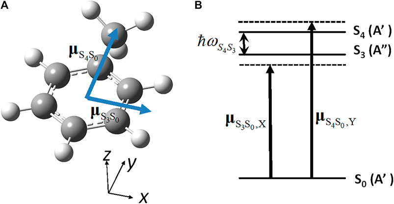
FIGURE 11. (A) Geometrical structure of toluene molecule (CS) in the ground state (S0) with the directions of the two electronic transition dipole moments; (B) Parameters for the three electronic states adopted to induce the unidirectional angular momentum:
Figure 12A shows the calculated time-dependent angular momentum expectation values LZ(t) with respect to the relative phase ζ = −π/2 (ζ = +π/2) between the two lasers for the left (right) panel. These were calculated using Eq. 35 combined with Eq. 34. Here, the amplitude of the electric field Fa is adopted as the input parameter F (≡ Fa). Other parameters are shown in Table 3A, while Table 3B shows the time-dependent populations in the three electronic states.
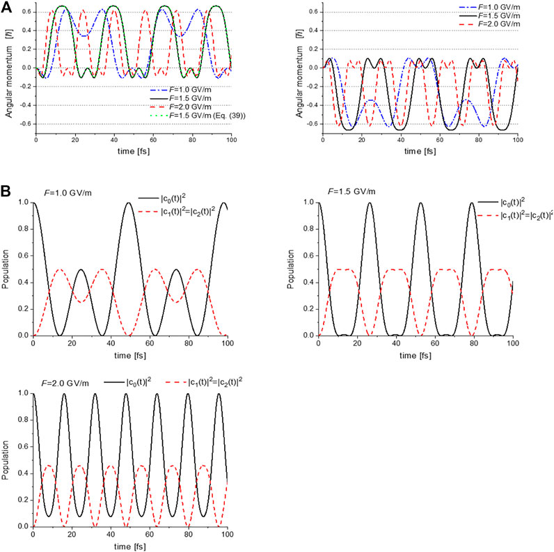
FIGURE 12. (A) Expectation values of the angular momentum operator LZ(t) for toluene, calculated with the laser input parameter values F = 1.0, 1.5 and 2.0 GV/m. The left (right) panel shows LZ(t) with respect to the relative phase between two lasers ζ = −π/2 (ζ = +π/2); (B) Temporal evolutions of the populations in S0, S3, and S4 for F = 1.0, 1.5 and 2.0 GV/m. Reprinted with permission from Ref. [43] Copyright (2016) Royal Society of Chemistry.
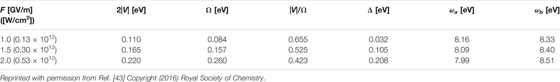
TABLE 3A. Input parameter F (≡ Fa) and other parameters for a generation of unidirectional π-electron rotation in toluene.
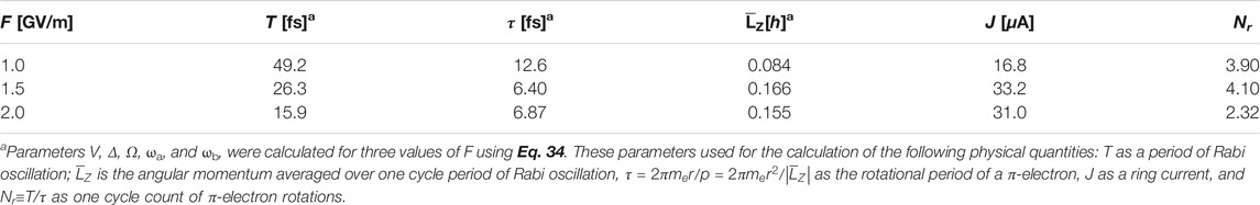
Table 3B. Calculated physical properties of the unidirectional π-electron rotation in toluene.
The time-dependent angular momenta plotted in Figure 12A are comprised of angular momentum pulse trains of the same shape for each value of F. Each angular momentum pulse corresponds to the unidirectional π-electron rotation, which begins with acceleration and ends with deceleration. The direction of the π-electron rotations is determined by the relative phase ζ between the two lasers: clockwise rotation for ζ=+π/2, and anti-clockwise rotation for ζ=−π/2. Here we discuss how the unidirectional π-electron rotations are created. We first note that LZ(t) can be rewritten under the two conditions, Eq. 34a and Eq. 34b, for Ω≈Δ as
Equation 36 expresses no unidirectional π-electron rotations. By introducing the third condition, Eq. 34c, which provides for the formation of the doubly degenerate dressed states with ζ = ±π/2, Eq. 36 can be expressed as
This indicates a unidirectional π-electron rotation whose direction is determined by the relative phase ζ, that is, LZ(t) > 0 for ζ = −π/2 and LZ(t) < 0 for ζ = +π/2, as demonstrated in Figure 12. The dotted line shown in Figure 12A represents
As demonstrated in Figure 12A, the oscillation periods of the angular momentum pulses become shorter (higher Rabi frequency Ω), and those amplitudes decrease as F increases. These two behaviors result from the third restriction condition for degeneracy (Eq. 35c) used in the derivation of LZ(t). This degeneracy condition should be satisfied for the two dressed states with equal energies to maintain their energies located at the center of the two excited states, even though the laser intensities of two lasers increase. This results in an increase in the detuning parameter Δ of the two lasers, that is, a decrease (increase) in ωa (ωb), as shown in Table 3A.
Figure 12A exhibits that the maximum magnitude of the angular momentum occurs in the vicinity of F = 1.5 GV/m. This can be explained by noting that the constant in Eq. 37,
Figure 12B shows the F-dependence of the
We now estimate the physical constants associated with π-electron rotations, which are listed in Table 3B: one cycle count of π-electron rotation Nr, and the magnitude of ring current J in one cycle of Rabi oscillation with periodicity T ≡ 2π/Ω. In particular for aromatic molecules the ring current is an important physical quantity because it is directly related to the magnetic field induced by the ring current. For simplicity, we consider the classical model of π-electron rotation, in which Nr is defined as Nr ≡ T/τ. Here
The ring current can be approximately expressed as
5 Summary and Perspective
This paper briefly provides an overview of the theoretical study of quantum laser control of coherent π-electron dynamics in low-symmetry aromatic ring molecules, which we have undertaken in recent several years [39–43, 68–73]. The essential principles to generate the π-electron angular momentum and ring current in a low symmetry aromatic ring molecule are first to create a superposition of two electronic excited (coherent) states using two linearly polarized lasers, and second to select the clockwise or anticlockwise rotational component from the non-stationary time evolution of the coherent state using pump and dump lasers with properly designed polarization directions. Here, the direct product of the irreducible representations of each excited states in the molecular point group belongs to that of the molecular rotation, (Rx, Ry or Rz), and the relative phase between the two linearly polarized lasers are fixed in order to determine the initial direction of the angular momentum and ring current. In additon to the laser conditions, aromatic ring molecules also need to satisfy the follwing conditions to generate the π-electron angular momentum and ring current. First two electronic excited states are nearly degenerate, and second, those states can be excited from the ground states using UV lasers, i.e., transitions between the electronic excited states and ground states are optically allowed.
On the basis of the above principles, analytical expressions for coherent π-electron angular momentum, ring current, and ring current-induced magnetic field are derived in the quantum chemical MO theory. A coherent π-electron ring current is defined as the average of the bond currents. Temporal behaviors of these coherent quantities are calculated using the density matrix method within the Markov approximation. Quantum simulations of the coherent quantuities have been performed for (P)-2,2’-biphenol. Based on the simulation results a new quantum control method for two-dimensional ultrafast angular momentum switching was proposed. The essential point of the quantum control is to use a sequence of the overlapped pump and dump pulses with a selected relative phase and selected polarization directions between the two lasers. The results for the (P)-2,2’-biphenol indicate that this new control scheme can potentially be used for the design and realization of ultrafast multi-dimensional electronic switching devices, or field-effect transistor devices.
The familiar quantum optimal control procedure was applied to an optiaml control of the coherent π-electron ring currents in planar PAHs with D2h symmetry. For this purpose, we have to set up the target state for a desired ring current pattern. The final target wave functions are determined via the Lagrange multiplier method by solving the coupled equations of motion under the constraints that the ring currents must satisfy. The method was applied to anthracene. The creation of the perimeter current and the middle ring current in anthracene were successfully realized. The control mechanisms were elucidated by analyzing the time-dependent behaviors of the control laser puses and the populations of the relevant electronic states. Concerning the types of molecules used in the above laser control studies, polycyclic planar aromatic molecules like PAHs, coronene and benzoic acids dimers are applicable for a laser control of perimeter or localized ring currents.
Another laser control method for the π-electrons unidirectional rotation in low symmetric aromatic rings was presented. The basic idea of the control method is to degenerate two nondegenerate excited states by using dynamic Stark shifts. Doubly degenerate excited state was created by the Stark shift using the two linearly polarized non-resonant lasers with a definite relative phase of
Some theoretical studies on laser control of the coherent π-electron rotations that were not included in this review are noteworthy. Probing molecular chirality, right-handed or left-handed chiral molecules, is a central issue in natural science. E.x., Phenylalanine is an essential amino acid, and L-enantiomer is found in natural system. On the other hand, D-enantiomer is synthesized artificially, and racemate phenylalanine is used for dietary supplement. However, in conventional methods such as CD spectroscopy and optical rotatory dispersion (ORD) spectroscopy [74, 75], the signals are very week because these processes involve second-order evaluations. As a possible of laser control scheme of the unidirectional π-electron rotations in low symmetric aromatic ring molecules, we previously proposed an efficient enantiomer-probing scenario for chiral aromatic molecule [71, 72]. A pair of nondegenerate excited states becomes degenerate by applying the dynamic Stark shift in the presence of two non-resonant UV lasers, producing an enantiomer-specific angular momentum. In that study, phenylalanine was adopted as an example for the numerical simulation. The resulting enantiomer-specific magnetic fluxes were on the order of a few Tesla, with periods of several tens of femtoseconds.
The contribution of vibrational motion to coherent π-electron rotations is also an important research topic that was not discussed in this review. In our previous research, vibrational effects on the coherent π-electron rotations in (P)-2,2’-biphenol were theoretically studied in the adiabatic approximation [73]. It was found that the low-frequency torsion mode around the bridge causes modulations in the beat of the ring current [73]. The vibrational effects on dynamic Stark-induced π-electron rotations in aromatic ring molecules with low symmetry were also studied using the displaced harmonic oscillator (DHO) model in the adiabatic approximation [72]. A pair of the lowest vibronic state in the two electronic excited states was degenerated using the two linearly polarized UV lasers. The two potential displacements between the ground state and the two electronic excited states were used as the parameters. The shapes of the sequential angular momentum pulses were affected by the potential displacements.
From one perspective, theoretical treatments beyond the adiabatic approximation [28, 31, 74–77] are expected to be incorporated such that other electronic excited states interact with the two relevant excited states through nonadiabatic couplings. It is crucial to clarify the effect of nonadiabatic couplings to the unidirectional π-electron rotations and determine how to maintain π-electron rotations by way of quantum optimal control techniques. In large PAHs, once π-electron rotation is realized at a localized ring site and once a site-selective coherent ring current is generated, the localized ring current is transferred from site to site using the laser pulses, i.e., transferred ring currents, which allow for an ultrafast switching function at the selected local site. Furthermore, the site-selective coherent ring current and transferred ring current can create the induced magnetic fields. These electromagnetic fields are expected to provide ultrafast probing of local sites in large molecular systems, biomolecules with chiral aromatic ring molecules, and PAHs. Further development of theoretical treatments involving photon-induced electronic coherence in molecular systems would be promising in the near future.
Author Contributions
The authors made a substantial, direct, and intellectual contribution to the work and approved it for publication. Original draft preparation, software, formal analysis, and funding acquisition, HM; Conceptualization, supervision, project administration, and validation, YF; Writing—original draft preparation, HM and YF; Investigation, writing—review and editing, HM, N-LP, and YF.
Conflict of Interest
The authors declare that the research was conducted in the absence of any commercial or financial relationships that could be construed as a potential conflict of interest.
Acknowledgments
HM and YF are grateful to Dr. M. Yamaki, and Professors Y. Teranishi, G-S. Kim, Y.J. Yan, and H. Nakamura for their contribution in earlier works. YF would like to thank Professor S. H. Lin for his critical comments and financial support.
References
1. Goulielmakis E, Loh Z-H, Wirth A, Santra R, Rohringer N, Yakovlev VS, et al. Real-time Observation of Valence Electron Motion. Nature (2010) 466:739–43. doi:10.1038/nature09212
2. Yuan K-J, Bandrauk AD Circularly Polarized Attosecond Pulses from Molecular High-Order Harmonic Generation by Ultrashort Intense Bichromatic Circularly and Linearly Polarized Laser Pulses. J Phys B: Mol Opt Phys (2012) 45:074001. doi:10.1088/0953-4075/45/7/074001
3. Chen S, Gilbertson S, Wang H, Chini M, Zhao K, Khan SD, et al. Attosecond Pulse Generation, Characterization and Application. Adv Multiphoton Process. Spectrosc (2011) 20:127–74. doi:10.1142/9789814343992_0004
4. Remacle F, Levine RD Attosecond Pumping of Nonstationary Electronic States of LiH: Charge Shake-Up and Electron Density Distortion. Phys Rev A (2011) 83:013411. doi:10.1103/PhysRevA.83.013411
5. Tzallas P, Skantzakis E, Kruse JE, Charalambidis D On the Generation of Intense Isolated Attosecond Pulses by Many-Cycle Laser Fields. In: Progress in Ultrafast Intense Laser Science. Heidelberg: Springer (2011). p. 163–90. doi:10.1007/978-3-642-18327-0_8
6. Ulusoy IS, Nest M Correlated Electron Dynamics: How Aromaticity Can Be Controlled. J Am Chem Soc (2011) 133:20230–6. doi:10.1021/ja206193t
7. Fujimura Y, Sakai H Electronic and Nuclear Dynamics in Molecular Systems. Singapore: World Scientific (2011). p. 117–32.
8. Singh KP, He F, Ranitovic P, Cao W, De S, Ray D, et al. Control of Electron Localization in Deuterium Molecular Ions Using an Attosecond Pulse Train and a Many-Cycle Infrared Pulse. Phys Rev Lett (2010) 104:023001. doi:10.1103/PhysRevLett.104.023001
9. Krausz F, Ivanov M Attosecond Physics. Rev Mod Phys (2009) 81:163–234. doi:10.1103/RevModPhys.81.163
10. Nest M, Remacle F, Levine RD Pump and Probe Ultrafast Electron Dynamics in LiH: A Computational Study. New J Phys (2008) 10:025019. doi:10.1088/1367-2630/10/2/025019
11. Kling MF, Vrakking MJJ Attosecond Electron Dynamics. Annu Rev Phys Chem (2008) 59:463–92. doi:10.1146/annurev.physchem.59.032607.093532
12. Skourtis SS, Beratan DN, Naaman R, Nitzan A, Waldeck DH Chiral Control of Electron Transmission through Molecules. Phys Rev Lett (2008) 101:238103. doi:10.1103/PhysRevLett.101.238103
13. NabekawaMidorikawa YK, Midorikawa K Nonlinear Optics for Characterizing XUV/Soft X-ray High-Order Harmonic Fields in Attosecond Regime. Adv Multiphoton Process. Spectrosc (2008) 18:1–67. doi:10.1142/9789812791740_0001
14. Lein M, Chirilă CC Signatures of Molecular Structure and Dynamics in High-Order Harmonic Generation. Adv Multiphoton Process. Spectrosc (2008) 18:69–106. doi:10.1142/9789812791740_0002
16. Remacle F, Nest M, Levine RD Laser Steered Ultrafast Quantum Dynamics of Electrons in LiH. Phys Rev Lett (2007) 99:183902. doi:10.1103/PhysRevLett.99.183902
17. Räsänen E, Castro A, Werschnik J, Rubio A, Gross EKU Optimal Control of Quantum Rings by Terahertz Laser Pulses. Phys Rev Lett (2007) 98:157404. doi:10.1103/PhysRevLett.98.157404
18. Klamroth T Optimal Control of Ultrafast Laser Driven many-electron Dynamics in a Polyatomic Molecule: N-Methyl-6-Quinolone. J Chem Phys (2006) 124:144310. doi:10.1063/1.2185633
19. Pershin YV, Piermarocchi C Laser-controlled Local Magnetic Field with Semiconductor Quantum Rings. Phys Rev B (2005) 72:245331. doi:10.1103/PhysRevB.72.245331
20. Niikura H, Légaré F, Hasbani R, Ivanov MY, Villeneuve DM, Corkum PB Probing Molecular Dynamics with Attosecond Resolution Using Correlated Wave Packet Pairs. Corkum PBNature (2003) 421:826–9. doi:10.1038/nature01430
21. Haruyama K, kono H, Fujimura Y, Kawata I, Bandrauk AD Intense Laser-Field Ionization of H2 Enhanced by Two-Electron Dynamics. Phys Rev A (2002) 66:043403. doi:10.1103/PhysRevA.66.043403
22. Anthony JE Functionalized Acenes and Heteroacenes for Organic Electronics. Chem Rev (2006) 106:5028–48. doi:10.1021/cr050966z
23. Bonifas AP, McCreery RL 'Soft' Au, Pt and Cu Contacts for Molecular Junctions through Surface-Diffusion-Mediated Deposition. Nat Nanotech (2010) 5:612–7. doi:10.1038/nnano.2010.115
24. BarthManz IJ, Manz J Periodic Electron Circulation Induced by Circularly Polarized Laser Pulses: Quantum Model Simulations for Mg Porphyrin. Angew Chem Int Ed (2006) 45:2962–5. doi:10.1002/anie.200504147
25. Barth I, Manz J, Shigeta Y, Yagi K Unidirectional Electronic Ring Current Driven by a Few Cycle Circularly Polarized Laser Pulse: Quantum Model Simulations for Mg−Porphyrin. J Am Chem Soc (2006) 128:7043–9. doi:10.1021/ja057197l
26. Barth I, Manz J Quantum Switching of Magnetic Fields by Circularly Polarized Re-optimized π Laser Pulses: From One-Electron Atomic Ions to Molecules. In: Progress in Ultrafast Intense Laser Science VI. Berlin, Heidelberg: Springer (2010). p. 21–44. doi:10.1007/978-3-642-15054-8_2
27. Nobusada K, Yabana K Photoinduced Electric Currents in Ring-Shaped Molecules by Circularly Polarized Laser Pulses. Phys Rev A (2007) 75:032518. doi:10.1103/PhysRevA.75.032518
28. Kanno M, Kono H, Fujimura Y Control of π-Electron Rotation in Chiral Aromatic Molecules by Nonhelical Laser Pulses. Angew Chem Int Ed (2006) 45:7995–8. doi:10.1002/anie.200602479
29. Kanno M, Hoki K, Kono H, Fujimura Y Quantum Optimal Control of Electron Ring Currents in Chiral Aromatic Molecules. J Chem Phys (2007) 127:204314. doi:10.1063/1.2806180
30. Kanno M, Kono H, Fujimura Y, Lin SH Nonadiabatic Response Model of Laser-Induced Ultrafastπ-Electron Rotations in Chiral Aromatic Molecules. Phys Rev Lett (2010) 104:108302. doi:10.1103/PhysRevLett.104.108302
31. Kanno M, Kono H, Fujimura Y Control of π-Electron Rotations in Chiral Aromatic Molecules Using Intense Laser Pulses. In: Progress in Ultrafast Intense Laser Science VII. Berlin, Heidelberg: Springer (2011). p. 53–78. doi:10.1007/978-3-642-18327-0_3
32. Barth I, Manz J, Serrano-Andrés L Quantum Simulations of Toroidal Electric Ring Currents and Magnetic fields in Linear Molecules Induced by Circularly Polarized Laser Pulses. Chem Phys (2008) 347:263–71. doi:10.1016/j.chemphys.2007.09.037
33. Yuan K-J, Bandrauk AD Attosecond-magnetic-field-pulse Generation by Coherent Circular Molecular Electron Wave Packets. Phys Rev A (2015) 91:042509. doi:10.1103/PhysRevA.91.042509
34. Steiner E, Fowler PW Patterns of Ring Currents in Conjugated Molecules: A Few-Electron Model Based on Orbital Contributions. J Phys Chem A (2001) 105:9553–62. doi:10.1021/jp011955m
35. Lazzerretti P Ring Currents. Prog Nucl Magn Reson Spectrosc (2000) 36:1–88. doi:10.1016/S0079-6565(99)00021-7
36. Redfield AG The Theory of Relaxation Processes. Adv Magn Reson (1965) 1:1–32. doi:10.1016/B978-1-4832-3114-3.50007-6
37. Lindblad G On the Generators of Quantum Dynamical Semigroups. Commun.Math Phys (1976) 48:119–30. doi:10.1007/BF01608499
38. Lin SH, Chang CH, Liang KK, Chang R, Shiu YJ, Zhang JM, et al. Ultrafast Dynamics and Spectroscopy of Bacterial Photosynthetic Reaction Centers. Adv Chem Phys (2002) 12:1–88. doi:10.1002/0471264318.ch1
39. Mineo H, Lin SH, Fujimura Y Coherent π-electron Dynamics of (P)-2,2′-biphenol Induced by Ultrashort Linearly Polarized UV Pulses: Angular Momentum and Ring Current. J Chem Phys (2013) 138:074304. doi:10.1063/1.4790595
40. Mineo H, Yamaki M, Teranishi Y, Hayashi M, Lin SH, Fujimura Y Quantum Switching of π-Electron Rotations in a Nonplanar Chiral Molecule by Using Linearly Polarized UV Laser Pulses. J Am Chem Soc (2012) 134:14279–82. doi:10.1021/ja3047848
41. Mineo H, Fujimura Y Quantum Design of π-Electron Ring Currents in Polycyclic Aromatic Hydrocarbons: Parallel and Antiparallel Ring Currents in Naphthalene. J Phys Chem Lett (2017) 8:2019–25. doi:10.1021/acs.jpclett.7b00704
42. Mineo H, Fujimura Y Quantum Control of Coherent π-electron Ring Currents in Polycyclic Aromatic Hydrocarbons. J Chem Phys (2017) 147:224301. doi:10.1063/1.5004504
43. Mineo H, Yamaki M, Kim G-S, Teranishi Y, Lin SH, Fujimura Y Induction of Unidirectional π-electron Rotations in Low-Symmetry Aromatic Ring Molecules Using Two Linearly Polarized Stationary Lasers. Phys Chem Chem Phys (2016) 18:26786–95. doi:10.1039/C6CP04254F
44. Oda K, Hita M, Minemoto S, Sakai H All-Optical Molecular Orientation. Phys Rev Lett (2010) 104:213901. doi:10.1103/PhysRevLett.104.213901
45. Stapelfeldt H, Seideman T Colloquium: Aligning Molecules With strong Laser Pulses. Rev Mod Phys (2003) 75:543–57. doi:10.1103/RevModPhys.75.543
46. Kanai T, Minemoto S, Sakai H Quantum Interference during High-Order Harmonic Generation From Aligned Molecules. Nature (2005) 435:470–4. doi:10.1038/nature03577
47. Frisch MJ, Trucks GW, Schlegel HB, Scuseria GE, Robb MA, Cheeseman JR, et al. Gaussian 09, Revision E.01. Wallingford, CT: Gaussian, Inc. (2009).
48. Baskin JS, Felker PM, Zewail AH Doppler‐free Time‐resolved Polarization Spectroscopy of Large Molecules: Measurement of Excited State Rotational Constants. J Chem Phys (1986) 84:4708–10. doi:10.1063/1.449998
49. Mineo H, Lin SH, Fujimura Y, Xu J, Xu RX, Yan YJ Non-Markovian Response of Ultrafast Coherent Electronic Ring Currents in Chiral Aromatic Molecules in a Condensed Phase. J Chem Phys (2013) 139:214306. doi:10.1063/1.4834035
50. Barth I, Manz J Electric Ring Currents in Atomic Orbitals and Magnetic Fields Induced by Short Intense Circularly Polarizedπlaser Pulses. Phys Rev A (2007) 75:012510. doi:10.1103/PhysRevA.75.012510
51. Barth I, Serrano-Andrés L, Seideman T Nonadiabatic Orientation, Toroidal Current, and Induced Magnetic Field in BeO Molecules. J Chem Phys (2008) 129:164303. doi:10.1063/1.2994737
52. Acremann Y, Buess M, Back CH, Dumm M, Bayreuther G, Pescia D A Single Ion as a Nanoscopic Probe of an Optical Field. Nature (2001) 414:49–51. doi:10.1038/35102129
53. Kruglyak VV, Portnoi ME, Hicken RJ Use of the Faraday Optical Transformer for Ultrafast Magnetization Reversal of Nanomagnets. J Nanophoton (2007) 1:013502. doi:10.1117/1.2516174
54. Kirilyuk A, Kimel AV, Rasing T Ultrafast Optical Manipulation of Magnetic Order. Rev Mod Phys (2010) 82:2731–84. doi:10.1103/RevModPhys.82.2731
55. Kanno M, Ono Y, Kono H, Fujimura Y Laser-Polarization Effects on Coherent Vibronic Excitation of Molecules with Quasi-Degenerate Electronic States. J Phys Chem A (2012) 116:11260–72. doi:10.1021/jp305284w
56. Bandrauk AD, Fujimura Y, Gordon RJ Laser Control and Manipulation of Molecules. Washington, DC: American Chemical Society (2002). p. 821. doi:10.1021/bk-2002-0821.fw001
57. Gordon R, Zhu LC, Seideman T Coherent Control of Chemical Reactions. Acc Chem Res (1999) 12:1007–16. doi:10.1021/ar970119l
58. Krause P, Klamroth T, Saalfrank P Time-dependent Configuration-Interaction Calculations of Laser-Pulse-Driven Many-electron Dynamics: Controlled Dipole Switching in Lithium Cyanide. J Chem Phys (2005) 123:074105. doi:10.1063/1.1999636
59. Zhu W, Botina J, Rabitz H Rapidly Convergent Iteration Methods for Quantum Optimal Control of Population. J Chem Phys (1998) 108:1953–63. doi:10.1063/1.475576
60. Zhu W, Rabitz H A Rapid Monotonically Convergent Iteration Algorithm for Quantum Optimal Control over the Expectation Value of a Positive Definite Operator. J Chem Phys (1998) 109:385–91. doi:10.1063/1.476575
61. Ohtsuki Y, Zhu W, Rabitz H Monotonically Convergent Algorithm for Quantum Optimal Control with Dissipation. J Chem Phys (1999) 110:9825–32. doi:10.1063/1.478036
62. Ferguson J, Reeves LW, Schneider WG VAPOR ABSORPTION SPECTRA AND OSCILLATOR STRENGTHS OF NAPHTHALENE, ANTHRACENE, AND PYRENE. Can J Chem (1957) 35:1117–36. doi:10.1139/v57-152
63. Rodriguez JJ, Mukamel S Probing Ring Currents in Mg-Porphyrins by Pump-Probe Spectroscopy. J Phys Chem A (2012) 116:11095–100. doi:10.1021/jp3035874
64. Yuan K-J, Shu C-C, Dong D, Bandrauk AD Attosecond Dynamics of Molecular Electronic Ring Currents. J Phys Chem Lett (2017) 8:2229–35. doi:10.1021/acs.jpclett.7b00877
65. Rugar D, Budakian R, Mamin HJ, Chui BW Single Spin Detection by Magnetic Resonance Force Microscopy. Nature (2004) 430:329–32. doi:10.1038/nature02658
66. Repp J, Meyer G, Stojković SM, Gourdon A, Joachim C Molecules on Insulating Films: Scanning-Tunneling Microscopy Imaging of Individual Molecular Orbitals. Phys Rev Lett (2005) 94:026803. doi:10.1103/PhysRevLett.94.026803
67. Sloan PA Time-resolved Scanning Tunnelling Microscopy for Molecular Science. J Phys Condens Matter (2010) 22:264001. doi:10.1088/0953-8984/22/26/264001
68. Yamaki M, Teranishi Y, Nakamura H, Lin SH, Fujimura Y The Generation of Stationary π-electron Rotations in Chiral Aromatic Ring Molecules Possessing Non-degenerate Excited States. Phys Chem Chem Phys (2016) 18:1570–7. doi:10.1039/C5CP05467B
69. Mineo H, Lin SH, Fujimura Y Vibrational Effects on UV/Vis Laser-Driven π-electron Ring Currents in Aromatic Ring Molecules. Chem Phys (2014) 442:103–10. doi:10.1016/j.chemphys.2014.02.011
70. Mineo H, Phan N-L, La D-K, Fujimura Y Theoretical Study of Dynamic Stark-Induced π-Electron Rotations in Low-Symmetry Aromatic Ring Molecules Beyond the Frozen Nuclear Approximation. J Phys Chem A (2021) 125:1476–89. doi:10.1021/acs.jpca.0c10216
71. Mineo H, Kim G-S, Lin SH, Fujimura Y Dynamic Stark-Induced Coherent π-Electron Rotations in a Chiral Aromatic Ring Molecule: Application to Phenylalanine. J Phys Chem A (2019) 123:6399–410. doi:10.1021/acs.jpca.9b03083
72. Mineo H, Kim G-S, Lin SH, Fujimura Y Quantum Design for Ultrafast Probing of Molecular Chirality through Enantiomer-specific Coherent π-Electron Angular Momentum. J Phys Chem Lett (2018) 9:5521–6. doi:10.1021/acs.jpclett.8b02137
73. Mineo H, Kanno M, Kono H, Chao SD, Lin SH, Fujimura Y Ultrafast Coherent Dynamics of Nonadiabatically Coupled Quasi-Degenerate Excited States in Molecules: Population and Vibrational Coherence Transfers. Chem Phys (2012) 392:136–42. doi:10.1016/j.chemphys.2011.11.004
74. Barron LD Molecular Light Scattering and Optical Activity. Cambridge, UK: Cambridge University Press (1982).
75.JM Hicks, eds. Chirality: Physical Chemistry. Washington, DC; American Chemical Society, (2002) 1–16.
76. Nakamura H Nonadiabatic Transition Concept, Basic Theories and Applications, Chapter 10. Multi-Dimensional Problems. Singapore: World Scientific (2012) 212–44.
77. de Vivie-Riedle R, Hofmann A Nonadiabatic Quantum Dynamics and Control Strategies. In: W Domcke, DR Yarkony, and H Köppel, eds. Conical Intersections, Electronic Structure, Dynamics & Spectroscopy. New Jersey: World Scientific, (2004) 803–27.
Appendix
A Brief derivation of target operators, calculated using the coupled equations for the ring current localization (Eq. 19).
In general, the Lagrange function
Where the first term
The partial derivatives of Eq. 19 with respect to
And
Respectively, where
By substituting the partial derivatives of
And
Equations (A2b), (A2c) can be expressed as
And
Equation (A4) contains the final equations, which are the same as those in Eq. 19.
B Brief derivation of target operators, calculated using the coupled equations for the perimeter ring current (Eq. 20).
Similar to the ring current localization, the Lagrange functional for the perimeter ring current is given as
Where
In the same manner as the ring current is localized to a designated ring, the coupled equations for the perimeter ring current are obtained by taking partial derivatives of the Lagrange functional
The coupled equations for the perimeter ring current can then be expressed as
And
C Calculated results of time-dependent coefficients
Equation 32 can be rewritten in the rotating approximation (RWA) as
Where
The coupled differential equations in Eq. (B1) are analytically solved under the two conditions described by Eqs. 34a, 34b by setting the initial condition:
Keywords: quantum control, electron dynamics, coherent ring current, ring current localization, angular momentum, quantum switching, Stark-induced degenerate electronic state
Citation: Mineo H, Phan N-L and Fujimura Y (2021) Quantum Control of Coherent π-Electron Dynamics in Aromatic Ring Molecules. Front. Phys. 9:675134. doi: 10.3389/fphy.2021.675134
Received: 02 March 2021; Accepted: 23 June 2021;
Published: 16 July 2021.
Edited by:
Philip Bucksbaum, Stanford University, United StatesReviewed by:
Sheng Meng, Institute of Physics (CAS), ChinaLuca Evangelisti, University of Bologna, Italy
Copyright © 2021 Mineo, Phan and Fujimura. This is an open-access article distributed under the terms of the Creative Commons Attribution License (CC BY). The use, distribution or reproduction in other forums is permitted, provided the original author(s) and the copyright owner(s) are credited and that the original publication in this journal is cited, in accordance with accepted academic practice. No use, distribution or reproduction is permitted which does not comply with these terms.
*Correspondence: Hirobumi Mineo, mineo@tdtu.edu.vn; Yuichi Fujimura, fujimurayuichi@m.tohoku.ac.jp