Molten Carbonate Fuel Cells for 90% Post Combustion CO2 Capture From a New Build CCGT
 Suzanne Ferguson*
  Anthony Tarrant
- Wood, Reading, United Kingdom
This paper presents the findings of the techno-economic assessment undertaken by Wood for the UK Government Department for Business, Energy and Industrial Strategy on the large-scale deployment of Molten Carbonate Fuel Cells (MCFCs) for post-combustion CO2 capture integrated with a new build combined cycle gas turbine power plant for the generation of low carbon electricity. The findings are compared with a state of the art proprietary amine scrubbing technology. Based on a new build power plant to be installed in the North East of England, with a power train comprising two trains of H-class gas turbines each with a dedicated steam turbine, the configuration presented utilises MCFCs between the gas turbine exhausts and their heat recovery steam generators and cryogenic separation for unconverted fuel recycle and CO2 purification. It was found that the proposed configuration could achieve 92% CO2 capture from the overall power plant with MCFCs while achieving 42% of additional new power production with only 2.6 %-points of thermal efficiency penalty compared to a conventional proprietary amine benchmark. While the total project capital cost increased by 65%, the high overall thermal efficiency and additional power generated resulted in a Levelised Cost of Electricity almost identical to the benchmark at £70/MWh (US$97/MWh). A number of areas are identified for potential further improvement in this scheme. It is concluded that use of MCFC technology, which also has the capability to be tailored for hydrogen production and combined heat and power services, shows significant potential to be competitive with, or exceed, the cost and technical performance of current state of the art technologies for post-combustion CO2 capture.
Introduction
In 2018, Wood completed an in-depth study for UK Government Department for Business, Energy and Industrial Strategy on the most promising CO2 capture technologies for large scale production of low carbon electricity and hydrogen including benchmarks for current state-of-the-art technologies as and two novel technologies (Department for Business et al., 2018).
While both molten carbonate fuel cells (MCFCs) and solid oxide fuel cells facilitate CO2 capture, and thus low carbon electricity generation, by keeping the fuel stream and the oxidant streams separate, MCFCs go one step further by also transferring CO2 from the oxidant side of the cell to the fuel side. A gas turbine flue gas stream contains sufficient oxygen to act as the fuel cells’ oxidant stream. Therefore, combining MCFCs with a combined cycle gas turbine (CCGT) power plant means that 90% of the CO2 from the gas turbine exhaust can be captured while generating additional electricity instead of decreasing the plant’s net power output. This technology is considered to currently be TRL-5, although pilot-testing at the James M. Barry Electric Generating Station in Alabama (News and Large Stationary, 2016), should increase this to TRL-6.
While the CCGT with MCFC concept was expected to be capital intensive, its efficiency was expected to be high enough to make the scheme worthy of assessment to explore if use of this technology for post-combustion CO2 capture had the potential to compete with, or exceed, the performance of current state-of-the-art proprietary amine solvents in this application once the technology has reached a suitable scale.
This paper presents the findings specifically for the MCFC case, compared with a proprietary amine solvent case to demonstrate the exciting potential of this technology in the configuration developed for the UK Government as well as highlighting further areas for potential improvement which could put this technology ahead of the current state-of-the-art.
Basis and Methodology
The study included Case 1, a CCGT power plant with 90% proprietary amine solvent post-combustion CO2 capture and Case 7, which used MCFCs as the post-combustion CO2 capture technology. In both cases the CCGT power island was modelled using Gatecycle and non-proprietary elements of the CO2 capture, compression and dehydration systems were modelled using Aspentech Hysys. Overall process heat and material balances were then brought together along with fuel cell performance calculations to perform the utility balance and hence describe the overall scheme.
Together, these key deliverables determined the efficiency and carbon balance of each case as well as providing the basis for a high-level equipment list from which the capital cost estimate was developed. At this level of study, this was done partly on the basis of costing individual equipment items in an in-house calibrated version of Aspentech Capital Cost Estimator (ACCE), and partly using vendor quotations or public domain data for packaged units, such as the MCFC stacks on a per MW installed capacity basis. The material balance was also combined with the capital cost estimate and an estimate of manpower requirements to determine the variable portion of the plant operating costs. Once the capital and operating costs had been determined it was possible to calculate illustrative overall project economics such as the Levelised Cost of Electricity (LCOE).
This process is summarized as follows:
• Simulation of base CCGT power plant, cross checked against public data such as Gas Turbine World
• CO2 capture process cost and performance provided by Shell Cansolv for proprietary amine solvent case and various technical papers and public domain references for FuelCell Energy’s DCF3000 units for the MCFC case (International Journal of Hydrogen Energy, 2010; Fuel Cell et al., 2015; Consonni et al., 2016; Forsyth et al., 2016; Fuel cell Energy, 2018).
• CO2 compression and dehydration simulated in Hysys and cross checked using recent vendor data for similar projects
• Heat and material balances and utilities summary provided the basis for thermal efficiency calculations, carbon balance, high level equipment sizing, capital and operating cost estimates and thus the calculation of LCOE.
The following generic bases defined both the MCFC and proprietary solvent cases presented in this paper:
• 2 × 9HA.01 gas turbines each with dedicated heat recovery steam generator and steam turbine.
• Greenfield site, coastal location in the North East of England.
• Annual average ambient conditions; 9°C, 80% humidity, 400 ppmv CO2 in air.
• United Kingdom grid natural gas fuel with an LHV of 46,470 kJ/kg, 3 ppmv H2S.
• CO2 compression to 110 bar (abs), 30°C, maximum 50 ppm H2O and 100 ppm O2 content.
• Baseload power generation at 90% availability for the overall plant.
• Q1 2017 cost figures in United Kingdom Pounds.
• Nth of a kind cost build up, no additional risk allowance added to the costing basis.
• Equity Finance with 8.9% discount rate.
• 25 year plant operating life with 4 year construction and commissioning period.
• Owners costs included as 7% of EPC contract cost.
• Prices of natural gas and CO2 emissions based upon UK Government profiles.
• Transport and storage cost for captured CO2 applied at plant battery limit as £19/tCO2
Details of additional basis assumptions, including infrastructure connections, design and regulatory costs, start-up, maintenance, labour, and so forth can be found in Potential Configurations for CCGTs With MCFC Post Combustion CO2Capture of the public domain report on the study for the UK Government (Department for Business et al., 2018).
Case 1—Natural Gas Combined Cycle Gas Turbine With Post-Combustion Capture
This case consists of a natural gas fired combined cycle power plant based upon 2 GE Frame 9HA.01 gas turbines each with a dedicated heat recovery steam generator (HRSG) and steam turbine in a 2 × 2 configuration. The flue gas from both HRSGs is routed to a single train Shell Cansolv proprietary post combustion CO2 capture unit, where it is cooled in a gas/gas heat exchanger, then boosted in pressure using a flue gas fan before entering a direct contact cooler (DCC). CO2 is captured from the cooled flue gas using an amine-based solvent in an absorption column and is released from the solvent in the stripper. The captured CO2 is then compressed in 4 stages, dehydrated and then compressed in a further stage to the required export pressure of 110 bar (abs). See Supplementary Figure S1 for block flow diagram.
Molten Carbonate Fuel Cell Material Balance
In order to develop low carbon power schemes incorporating MCFCs, particularly material balances, it is necessary to extract the core chemistry and anticipated thermal performance from the literature. When operating at 650°C, the following reactions occur within the MCFCs:
• Hydrocarbon Reforming (CH4 onlyshown)
• Water-gas shift
• Hydrogen conversion at anode
• CO3 formation at cathode
• Theoretical overall reaction
Scrutinizing the material balances shown in the literature (Fuel Cell, 2015) showed that it could be assumed that the reforming reaction goes to completion under these conditions and that the shift reaction goes to approximately 70% conversion.
In carbon capture mode FuelCell Energy quote their 2.8 MW DFC3000 fuel cell as capturing about 2,300 kg/h of external CO2. For our scale of CCGT, with 2 × 9HA.01 GTs, this would require 440 MW installed capacity of fuel cell stacks. The once through LHV thermal efficiency of the fuel cells, as an individual item, is quoted as 47% on an LHV basis (Fuel cell Energy, 2017), but if the unconverted fuel species are recycled then this raises to 70–75% for the MCFC system.
Potential Configurations for Combined Cycle Gas Turbines With Molten Carbonate Fuel Cell Post Combustion CO2 Capture
There are a number of different configurations in which MCFCs can be used for post combustion CO2 capture from CCGTs, with the following options defining many possibilities:
• Internal (withing the fuel cell) or external (upstream) reforming, we have considered only internal reforming options in our studies.
• Locate fuel cells between GT and HRSG or downstream HRSG (greenfield or retrofit).
• Utilisation of unconverted fuel species in anode exhaust:
• Oxy-combustion with heat integration.
• Recycle to GT.
• Recycle to Fuel cell.
• CO2 purification methodology.
MCFCs can be retrofitted as a bolt-on-the-back CO2 capture technology analogous to an amine solvent post-combustion system, as shown in the Supplementary Figure S2. This would be the simplest configuration for retrofit to an existing CCGT or flue gas source. However, since the fuels cells operate at very high temperature, this configuration requires reheating of the gas turbine exhaust. A further potential configuration that was considered early in MCFC configuration development was location of the MCFCs downstream of the heat recovery steam generator is shown in the Supplementary Figure S2.
To make the most of the very high temperature between the gas turbine and its heat recovery steam generator, an alternative configuration, applicable particularly to new-build plants, would be to locate the MCFCs between these two, as shown in the Supplementary Figure S3.
The Supplementary Figure S3 also shows the unconverted fuel species in the MCFC fuel side exhaust being combusted with oxygen in a second heat recovery boiler scheme based on work undertaken by Politecnico di Milano (International Journal of Hydrogen Energy, 2010; Fuel Cell et al., 2015; Consonni et al., 2016). A similar scheme presented by the same team shows the alternative of using cryogenic separation to separate the CO2 product from the unconverted fuel species, as shown in the following Supplementary Figure S4.
The scheme above has the anticipated advantage of being able to more directly control the purity of the CO2 product. Subsequent work by the Carbon Capture Project (CCP) (Forsyth et al., 2016) found that slightly higher thermal efficiency of the overall scheme could be achieved by recycling the recovered unconverted fuel species to the fuel cell rather than the gas turbine and thus this following configuration was selected as our basis for further techno-economic assessment as shown in Figure 1.
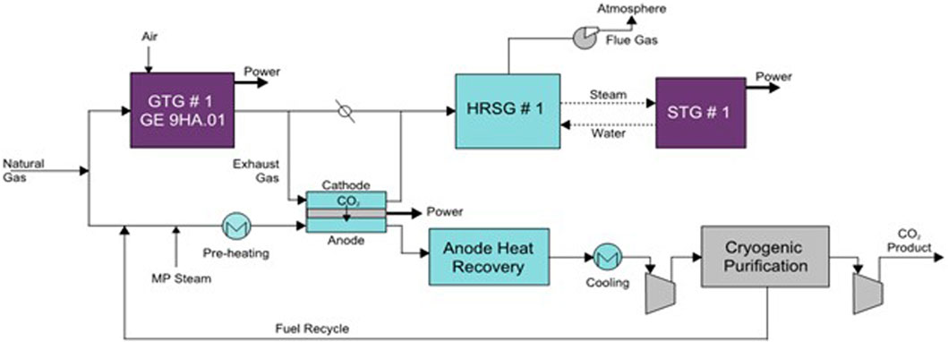
FIGURE 1. CCGT with MCFCs, cryogenic separation and fuel recycle to MCFCs—selected configuration for this study.
In summary, the above configuration was selected due to the study basis specifying a new-build plant, with an emphasis on a balance of controllability and maximum thermal efficiency as shown in the preceding literature at the time.
Physical Integration of Combined Cycle Gas Turbine and Molten Carbonate Fuel Cells
The block flow diagram presents how the main process flows would be configured, however, physical integration of many fuel cell units, two gas turbines and their respective heat recovery steam generators connected by large cross sectional area duct work is logistically challenging. FuelCell energy have undertaken work separately investigating logistics of how best to arrange a large number of their stacks. This resulted in the following design which incorporates 208 individual fuel cells stacks into a single enclosure where each enclosure features a dedicated flue gas feed/exhaust gas heat recovery exchanger as shown in Figure 2.
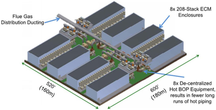
FIGURE 2. Sketch of a 350 MWe MCFC Installation (Image courtesy of FuelCell Energy Inc. based upon work supported by the US Department of Energy under Award Number DE-FE0026580).
To modify the above concept to fit the capacity required for our study, since our basis uses larger gas turbines, Wood have made the following adaptations:
• Larger square ductwork with single inlet and single outlet of graduated cross-sectional area.
• 5 × gas/gas heat exchangers per gas turbine train.
• 5 × 208-stack enclosures per gas turbine train.
The material of construction for equipment and ducting must be suitable for both high temperature and presence of carbon monoxide and hydrogen. This is a very challenging service for materials and we have assumed a high grade nickel alloy (UNS N06696) is required. Minimizing the quantity of such an expensive material of construction would be a key area in the design where costs could be reduced with further work, or substitution with alternative material as long as it is demonstrated to be able to withstand the duty without compromising safety.
Fuel cell stack lifetime is another area which has significant impact on the overall cost of the scheme. FuelCell Energy deem a 7 year lifetime to be an achievable target, therefore our study assumed that the stacks would require replacement every 7 years. It is important to include this cost in the overall plant economics.
Techno-Economic Performance Results
The technical and economic performance results for Case 1, CCGT with amine solvent and Case 7, MCFC post combustion CO2 capture are summarised in the following Supplementary Table 1 compared with a conventional CCGT without any CO2 capture.
The MCFC case captures 90% of the CO2 from the GT exhausts and electrochemically consumes additional fuel, from which 100% of the CO2 emitted is captured while producing additional power, the net effect of which is an increase in net power production and only a minimal 2.6% point net efficiency loss compared to an unabated CCGT plant.
The following points can be highlighted as basic differences in technical performance between the two cases:
• Both cases use the same high efficiency gas turbine power island configuration while the MCFC case adds the fuel cells, which have a gross LHV efficiency of ∼75%. Thus, this case benefits from a very high efficiency underlying power production before any parasitic loads for carbon capture are applied.
• The parasitic loads associated with the CO2 capture and compression process result in a net exportable power from the CCGT with MCFC case of 444 MWe more than the amine solvent case, but with additional fuel electrochemically consumed. These balance each other to some extent, such that there is still a reduction in efficiency vs. the unabated case, but only of 2.6% lower net LHV efficiency.
• Although the MCFCs require a significant amount of steam for the reforming and shift steps within the cell, this steam can be generated via heat recovery from the fuel cell exhaust.
• CO2 compression power appears high compared to some schemes because the first compression stages are also compressing the unconverted hydrogen, CO and water vapour prior to the cryogenic purification and fuel recycle step.
• The carbon efficiency for the CCGT with MCFC case is 8% of the Reference unabated case as this case captures 92% of the total CO2 produced.
The total project cost for the CCGT with MCFC case is 62% higher than the amine solvent case but produces 42% more net power output. The following additional points can be highlighted as basic differences in economic performance between the two cases with post combustion CO2 capture:
• The MCFC system includes several high capital cost elements, including the MCFC cells themselves and exotic materials required for heat exchangers downstream of the fuel cell and high temperature ducting.
• Operating costs are high for this case primarily because the MCFC stacks are assumed to be replaced every 7 years.
• Despite the capital and operating costs being substantially higher for the MCFC case, the Levelised cost of electricity (LCOE) is almost identical to the amine case at £70.7/MWh, compared to the £69/9/MWh for the amine case. This is largely due to the very high thermal efficiency of this case combined with very low residual carbon emissions.
It should be noted that the UK has a penalty for CO2 emissions which consequently rewards projects with lower residual CO2 emissions, and has a very large cost impact on any project which does not feature carbon capture and storage. This is reflected in the table above, with both low carbon electricity generation cases having a lower LCOE than the unabated fossil fuel power generation case. In this instance, where it can be considered that any new power plant with CCS is displacing an unabated plant from the grid, the cost of CO2 avoided can be defined as the additional cost per unit of power produced divided by the delta carbon footprint between the plants with and without CO2 capture. Since this study demonstrates lower LCOE for both abated plants, their cost of CO2 avoided is negative.
Potential for Further Improvement
The results presented in this paper have drawn upon years of development undertaken by others investigating potential flow scheme configurations to integrate MCFCs with CCGTs. However, we are confident that further optimisation of heat integration alternatives vs. capital and operating costs could result in a more cost effective or more thermally efficient scheme, particularly paying attention to heat recovery from the fuel cell exhaust gas.
All cases developed for the UK Government considered baseload power plants which would operate for the majority of the year, providing a base level of low carbon power at all times. However, there is an increasing need for low carbon power plants to be able to respond to changes in demand to balance production from variable renewables such as offshore wind. Therefore, an assessment of potential for flexible operation of the overall plant to meet grid demands for flexible/dispatchable low carbon operation should be undertaken.
Most power plants can achieve increased overall thermal efficiency, as well as their value to society, by incorporating heat provision alongside power generation, particularly if value can be realised for low grade heat. The scheme incorporating MCFCs may also be able to provide further potential combined heat and power benefits as the large scale MCFC installation already in operation provides this.
MCFCs generate hydrogen as part of the internal chemistry inherent to the fuel cell. FuelCell Energy have advised that their stack can also be used to provide a pure hydrogen stream which is anticipated to be highly important as an energy vector for decarbonisation. Anticipated uses for such a hydrogen stream include its used as a transport fuel, a low carbon fuel for domestic and commercial space and water heating, and as an energy storage medium, whereby hydrogen is generated at times of low grid power demand and used for peak power generation, either via combustion in dedicated gas turbines or in hydrogen fuel cells. The ability to add alternative revenue streams via hydrogen sales can substantially improve the already competitive performance of this technology for post-combustion CO2 capture compared to conventional state-of-the-art technologies.
Conclusion
This study presents findings of a techno-economic assessment comparing the use of MCFCs and proprietary amine-based solvents for baseload low carbon power generation using post combustion CO2 capture.
It was found that incorporating MCFCs between each gas turbine and its respective heat recovery steam generator, using cryogenic separation to purify the CO2 and recycling the unconverted fuel species back to the fuel cell could achieve 92% CO2 capture by adding 440 MWe of fuel cells. Other findings included:
• Net power production increased by 42% in MCFC case vs. amine case.
• Thermal efficiency penalty improved from 7.4 %-points to 2.6 %-points in MCFC case.
• Total CO2 captured increased from 2.9 to 3.8 MTPA.
• Total project cost increased by 65%, but specific project cost (per kW) increased by 14%.
• Total operating cost (before fuel and carbon price) increased by 64%.
• Income from electricity sales increased by 43%.
The increased capital and operating costs are balanced out by the increased power production, high thermal efficiency and lower residual CO2 emissions to result in an LCOE almost identical to that of the amine-based technology at £70.7/MWh and £69.9/MWh for the MCFC and amine technologies respectively.
Wood anticipate that this scheme may have significant additional advantages yet to be understood, such as flexibility to meet grid demand and ability to produce hydrogen as well as further potential for optimisation of the design presented.
Data Availability Statement
Publicly available datasets were analyzed in this study. This data can be found here: https://www.gov.uk/government/publications/call-for-ccus-innovation-literature-review-benchmarking-report-and-calculator.
Author Contributions
This paper was authored by SF and reviewed and checked by AT. Preceding work is referenced in the reference list.
Funding
Development of this paper was funded by Wood.
Conflict of Interest
Authors SF and AT were employed by the company Wood.
Acknowledgments
The authors would like to thank the UK Government Department for Business, Energy and Industrial Strategy for funding the original study and giving permission to share the learnings from it. We would also like to thank FuelCell Energy for their vital input to this work. Finally, we would like to thank Tim Barckholtz for inviting us to submit a paper to this journal and helping us keep up to date with MCFC developments.
Supplementary Material
The Supplementary Material for this article can be found online at: https://www.frontiersin.org/articles/10.3389/fenrg.2021.668431/full#supplementary-material
References
Consonni, S., Viganò, F., Martelli, E., Gatti, M., Bona, D. D., Capra, F., et al. (2016). CCP Novel CO2 Capture Technology Evaluation: WP1 MCFC Package. LEAP, 151.
Department for Business (2018). “Benchmarking State-Of-The-Art and Next Generation Technologies, Assessing the Cost Reduction Potential and Competitiveness of Novel (Next Generation) UK Carbon Capture Technology,” in Wood and Department for Business, Energy and Industrial Strategy. Editors R. Ray, S. Ferguson, and A. Tarrant Available at: https://www.gov.uk/government/publications/call-for-ccus-innovation-literature-review-benchmarking-report-and-calculator.
Forsyth, F., Lodge, S., Consonni, S., Bona, D. D., Gatti, M., Martelli, E., et al. (2016). “Evaluation of Five Alternative CO2 Capture Technologies with Insights to Inform Further Development,” in 13th International Conference on Greenhouse Gas Control Technologies, GHGT-13 (Lausanne, Switzerland: Energy Procedia).
Fuel cell Energy (2018). Publicity Material from Fuel Cell Energy. Available at: http://www.fuelcellenergy.com/assets/DFC-CarbonCapture-White-Paper.pdf.
Fuel cell Energy (2017). SureSource 3000 2.8 Megawatts Product Specification. Available at: https://www.fuelcellenergy.com/wp-content/uploads/2017/02/Product-Spec-SureSource-3000.pdf.
Fuel Cell (2015). “Molten Carbonate Fuel Cells as Means for PostCombustion CO2 Capture: Retrofitting Coal-Fired Steam Plants and Natural Gas-Fired Combined Cycles,” in 2015 Proceedings of the ASME 2015 13th International Conference on Fuel Cell Science, Engineering and Technology. Editors M. Spinelli, S. Campanari, and M. C. Romano (Thomas G. Kreutz of Princeton Environmental Institute, Hossein Ghezel-Ayagh, Stephen Jolly & Matthew Di Nitto of Fuel Cell Energy, Inc.).
International Journal of Hydrogen Energy (2010). CO2 Cryogenic Separation from Combined Cycles Integrated with Molten Carbonate Fuel Cells. Miami: Paolo Chiesa, Stefano Campanari & Giampaolo Manzolini of Politecnico di Milano.
Keywords: CO2 capture, post combustion, fuel cells, CCS, low carbon electricity
Citation: Ferguson S and Tarrant A (2021) Molten Carbonate Fuel Cells for 90% Post Combustion CO2 Capture From a New Build CCGT. Front. Energy Res. 9:668431. doi: 10.3389/fenrg.2021.668431
Received: 16 February 2021; Accepted: 23 June 2021;
Published: 21 July 2021.
Edited by:
Stefano Consonni, Politecnico di Milano, ItalyReviewed by:
Luca Mastropasqua, University of California, Irvine, United StatesHossein Ghezel-Ayagh, FuelCell Energy, United States
Copyright © 2021 Ferguson and Tarrant. This is an open-access article distributed under the terms of the Creative Commons Attribution License (CC BY). The use, distribution or reproduction in other forums is permitted, provided the original author(s) and the copyright owner(s) are credited and that the original publication in this journal is cited, in accordance with accepted academic practice. No use, distribution or reproduction is permitted which does not comply with these terms.
*Correspondence: Suzanne Ferguson, suzanne.ferguson@woodplc.com