Sensitivity Study of the Influence of Blade Sectional Stiffness Parameters on the Aeroelastic Response of Wind Turbines
 Cheng Chen
 Tongguang Wang*
 - Jiangsu Key Laboratory of Hi-Tech Research for Wind Turbine Design, Nanjing University of Aeronautics and Astronautics, Nanjing, China
With the development of wind turbines as a result of large-scale and offshore trends, the wind turbine size is becoming increasingly larger. The passive control technique is used to alleviate the increasing loads on the blade for the sake of improving the durability of the wind turbine. The ply design of shells considering the coupling effect of bending and torsion is one of the passive control techniques. The bending torsion coupling stiffness is one of the parameters of the blade section stiffness matrix. In order to fully understand the influence of each blade stiffness parameter on the aeroelastic responses of wind turbines and to consider the influence of structural characteristics on the aeroelastic responses in blade design, the influences and sensitivity of each stiffness parameter in the 6 × 6 stiffness matrix of the blade sections on the aeroelastic responses of the wind turbines are systematically studied under steady wind condition. The aerodynamic forces in the aeroelastic model are calculated by an AeroDyn module based on blade element momentum theory, and the structural dynamic responses of the blade are calculated using generalized Timoshenko beam theory and geometric exact beam theory. The NREL baseline 5 MW wind turbine and blade properties are used in this study, where the diagonal stiffness parameters and non-diagonal stiffness parameters of the matrixes of each blade section are scaled according to certain principles. The results show that the axial stiffness, the flap-wise stiffness, and the torsional stiffness in the diagonal are sensitive to the root loads and tip displacement of the blade. The flap-wise bending torsion coupling stiffness, the flap-wise shear-torsion coupling stiffness, and the edge-wise shear-torsion coupling stiffness in the non-diagonal are also sensitive to the aeroelastic responses. For completeness, the effects of other stiffness parameters on the aeroelastic responses are also analyzed and discussed.
Introduction
In order to reduce the cost of energy (COE) in the wind industry, the wind turbine tends to be designed to be larger and larger. Long blades mean high slenderness ratios, heavy weight, and high extreme load and fatigue load. In order to meet the needs of high stiffness and long fatigue life of the blade, the design method and structure optimization of the continuously upsized blade are both challenging. The most direct way to achieve this goal is to reduce the load on the wind turbine blade in an aeroelastic response. The popular load control methods can be divided into two categories: active control technology and passive control technology. Because the passive control technology does not need driving equipment and has the advantages of fast response and low cost, it is a supplement to the active control method. The ply design of shells considering the coupling effect of bending and torsion is one of the passive control techniques. When the blade is bent, the coupling effect of bending and torsion is used to change the angle of attack to reduce the load.
In order to analyze the influence of blade flexibility and bending torsion coupling effect, and to meet the design requirements of the flexible blade, advanced modeling technology is needed. The CFD/CSD-coupled wind turbine aeroelastic response analysis method may be the development trend of the future, but at this stage, it is not widely used in engineering due to the limitation of computing resources. The aeroelastic analysis model that combines blade element momentum theory with beam theory is the most widely used in engineering. Based on the assumption of small deformation, linear beam theory is gradually replaced by nonlinear deformation beam theory in the analysis of large deformation flexible blades owing to the calculation accuracy (Kim et al., 2013; Gebhardt and Roccia, 2014). Based on the variational asymptotic method (Berdichevskii, 1979) and the conservation of strain energy, 3D analysis of slender beam structure can be decomposed into nonlinear beam theory and section properties analysis theory, which can provide a complete 6 × 6 stiffness matrix.
Larsen et al. (2004) studied the influence of large deformation of the blade on the power of wind turbine. His research results show that the main influence caused by large deformation is to change the effective area of the wind turbine, which can reduce the power under low wind speed conditions, and also reduce the pitch angle under high wind speed conditions, and it can improve the bending moment and reduce the thrust of the wind turbine. Ahlström (2006) studied the influence of different slenderness ratios of a 2 MW blade on the wind turbine according to the same idea. The method of changing the slenderness ratio is to scale the stiffness and mass properties of the blade section equivalently. His research shows that when the tip deformation in the direction of blade waving reaches and exceeds 10% of the blade length, the power of the fan will decrease significantly. Then, Ponta et al. (2016) used the NREL 5 MW to study the influence of wind turbine deformation. The results show that even in the case of small deformation, in order to maintain stable power in the aeroelastic response, a smaller pitch angle is needed when the wind speed is higher than the rated wind speed.
The passive load control technology is realized by the bending torsion coupling effect of the composite blade. The bending torsion coupling effect can be realized by material bending torsion coupling or geometric bending torsion coupling of composite blades (Ashwill et al., 2010; Larwood et al., 2014). The coupling effect of bending and torsion can be reflected in the stiffness matrix of the blade section. Lobitz and Veers (1998) of SNL are the first to study adaptive blade passive load shedding. Their research shows that the bending torsion coupling has an obvious effect on the fatigue load reduction of the wind turbine. Hayat and Ha (2015) further studied the relationship between the bending torsion coupling degree and the reduction of fatigue load. The bending torsion coupling degree is realized by changing the ply angle and the asymmetry of the ply. Gozcu et al. (2014) also show that the bending torsion coupling effect of the blade can reduce the fatigue load of the wind turbine. Vesel and McNamara (2014) studied the optimal design of blade based on aeroelastic response and bending torsion coupling effect with minimum COE as the optimization objective.
It can be found that there are abundant research results on the influences of large deformation and bending torsion coupling effect of the blade, but it is noted that the flap-wise stiffness and bending torsion coupling stiffness of flexible blade only account for a part of the complete composite beam section stiffness matrix, as shown in Figure 1 (coupling deformation is illustrated by the plate in the figure). However, the effects of other coupling terms on the aeroelastic response are rarely studied.
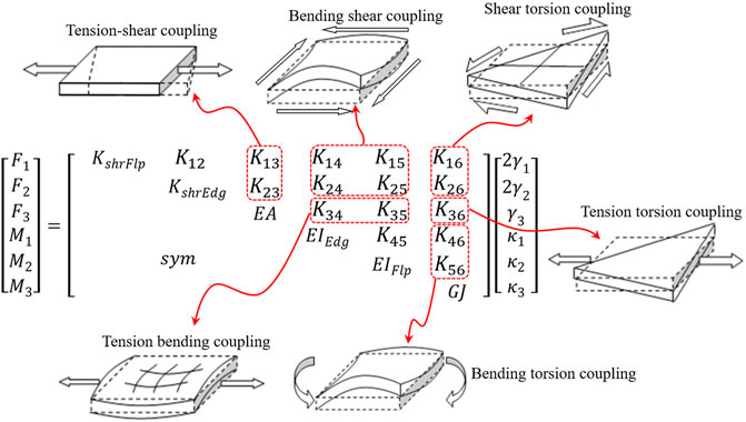
FIGURE 1. Stiffness matrix of composite beam section.
In order to systematically analyze the influence of each stiffness coefficient in the section stiffness matrix of the composite blade on the load and structural response in the aeroelastic response analysis of wind turbine, this paper takes the NREL 5 MW wind turbine as the benchmark model to adjust the parameters of the blade’s stiffness matrix. Based on the BEM method and Aerodyn module, the aeroelastic response of the wind turbine and the load of each component are obtained. The influence of each stiffness coefficient on the aeroelastic response of the wind turbine is obtained by using the Sensitivity Analysis Factor (SAF). The results of this paper reveal the sensitivity of blade stiffness to wind turbine aeroelastic response and load and improve the understanding of wind turbine coupling mechanisms. In the future aeroelastic simulation and blade design, the influence of coupling stiffness should be considered actively to make more effective use of the influence of favorable factors and avoid the influence of unfavorable factors so as to provide theoretical support for the formation of more advanced wind turbine blade design method.
Model Description
The aeroelastic simulation analysis model of wind turbine combines blade element momentum (BEM) theory and nonlinear beam theory based on geometrically exact beam theory (GEBT). BEM theory has high calculation efficiency and stable results, and the accuracy can meet the needs of engineering design. The GEBT, also known as the generalized Timoshenko beam theory, can simultaneously consider the large flexible deformation of the blade and the complete 6 × 6 stiffness matrix of the blade sections.
Aerodynamic Model
After years of development and revision, BEM theory is relatively mature. There are many studies about BEM theory; for example, the complete derivation process is discussed in many works related to wind turbine design (Manwell et al., 2009; Tongguang Wang and Qian., 2019). BEM theory consists of two parts: momentum theory and blade element theory. In momentum theory, it is assumed that the wind turbine is a penetrating disk and the flow is stable. The wind turbine absorbs the kinetic energy in the wind and converts it into mechanical energy. Blade element theory, also known as strip theory, simplifies wind turbine blades into a finite number of blade segments superimposed along the radial direction. It is assumed that the flow between each blade element does not interfere with each other, and the aerodynamic force acting on each blade element is only determined by its airfoil and local inflow velocity. The blade element momentum method is to solve the momentum theory and blade element theory simultaneously to obtain the aerodynamic load of each blade element and then obtain the aerodynamic performance of the whole blade.
In order to ensure the accuracy of BEM theory, many scholars have put forward a variety of correction methods for the original theory after years of research. For example, tip loss correction (Glauert, 1935), hub loss correction (Glauert, 1935), correction of large thrust coefficient (Glauert, 1926; Buhl, 2005), skewed wake correction (Pitt and Peters, 1980), etc. When the wind turbine operates in an unsteady state, the angle of attack of the wind turbine section will be unsteady. If the unsteady flow separation occurs, the obvious unsteady aerodynamic load will be caused. The B-L dynamic stall model is adopted, which is based on Leishman and Beddoes (1989). In fact, the rotation of the blade will produce Coriolis force and centrifugal force and then cause stall delay phenomenon, resulting in the so-called three-dimensional rotation effect. Based on different theories, scholars have developed a series of three-dimensional rotation effect correction models (Corrigan and Schillings, 1994; Du and Selig, 1998; Chaviaropoulos and Hansen, 2000). Most of these models adopt the following forms to modify the aerodynamic force:
where
Structural Dynamic Model
The nonlinear beam model based on geometrically exact beam theory is used in structural dynamics. According to GEBT, the position vector of any point on the beam with initial bending and torsion can be described as follows:
where
Based on the definition of the position vector, the kinetic energy K and the strain energy U of the beam can be obtained by using the Hamilton principle as follows. The detailed derivation process can be found in Hodges’ literature (Hodges, 1990).
where
Using the definition of generalized strain and velocity,
where
The nonlinear governing equations are solved by the Newton-Raphson method, and the linearized equations described by incremental expressions are obtained. The linear equations are discretized by the finite element method, and the discretized linear governing equations are obtained as follows:
where
Stiffness Adjustment Strategy
The reference model of the NREL 5 MW wind turbine is taken as the baseline model. Detailed parameters of the baseline model can be found in the technical report (Jonkman et al., 2009). The GEBT can consider a complete 6 × 6 stiffness matrix. By setting different stiffness coefficients in the stiffness matrix and then calculating the aeroelastic response of the wind turbine, the corresponding influence of each stiffness coefficient on the aeroelastic response of the wind turbine can be obtained. In order to intuitively analyze the sensitivity of stiffness to aeroelastic response and avoid the influence of other factors, the parameters other than the stiffness matrix are fixed. The stiffness coefficient is adjusted in the following two ways.
For the main diagonal of the stiffness matrix, the stiffness factor is set as follows:
where
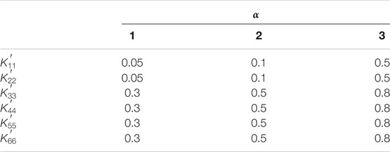
TABLE 1. scaling factor.
For the non-main diagonal of the stiffness matrix, the stiffness factor is set as follows:
where
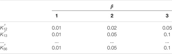
TABLE 2. scaling factor.
Simulation Analysis Results of Steady Wind Condition
To validate the accuracy of the aeroelastic analysis method combined with Aerodyn and GEBT, the aeroelastic response calculation results of the baseline model under steady-state wind conditions are compared with those of the commercial software SIMPACK. The initial rotation speed of the wind turbine is 5 RPM. The wind speed is kept at 12 m/s. The simulation time is 200s.
The comparison results of simulation analysis are shown in Figure 2. Figures 2A,B show the comparison of generator power and rotation speed under 200 s steady-state wind conditions. The simulation results of SIMPACK and this method are basically consistent. Figures 2C–F show the comparison between the calculated results of tip deformation and root load. During the start-up period of 0–50 s, the tip deformation fluctuates irregularly, and the wind turbine entered a stable state after 50 s. The amplitude of the tip displacement in the out-of-plane direction of this method is obviously larger than that of SIMPACK, and the calculated results of the mean value in this direction are close to each other. The results of the two methods are close to each other in the in-plane displacement amplitude, and the mean value of this method is slightly larger than that of SIMPACK. The amplitude and maximum of the blade root bending moment in the out-of-plane direction of the wind turbine calculated by this method are greater than those calculated by SIMPACK, and the blade root bending moment in the in-plane direction calculated by the two methods is almost the same.
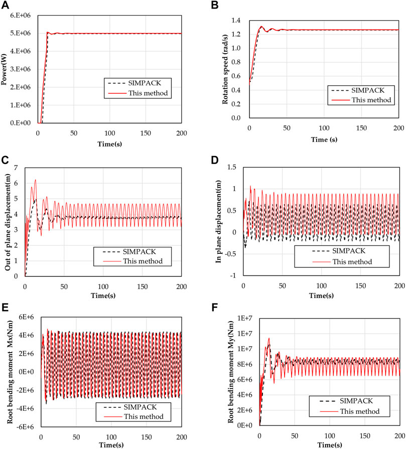
FIGURE 2. Comparison of aeroelastic response results of blades under steady wind condition.
It can be seen from the results of a steady-state aeroelastic simulation that this method and SIMPACK aeroelastic simulation system can achieve the expected aeroelastic simulation effect by adopting the same unit setting and the same control strategy. The comparison results show that the calculation results of this method are reliable.
The same steady-state wind condition and initial condition are used for sensitivity analysis. In the design of wind turbine components, the load is one of the main input parameters, so the sensitivity of blade stiffness to blade root moment is taken as the main research object.
Taking the effect of flap-wise stiffness on the aeroelastic response of wind turbine as an example, Figure 3 and Figure 4 show the influence of flap-wise stiffness on power and pitch angle, and the influence of flap-wise stiffness on blade tip deformation, respectively. The ‘5_5_0.3’ in the legend means the EIflap in the stiffness matrix of Figure 1 is 0.3 times of the baseline model. It can be seen from Figure 3 that when the flap-wise stiffness is smaller, the output power of the wind turbine is more difficult to maintain stability. Especially, when the flap-wise stiffness decreases to 30% of the baseline model, the blade tip deformation is too large to capture enough wind energy, even when the pitch angle is adjusted to 0, it still can not provide enough lift and torque, and the output power can not reach the rated power. The results are consistent with the previous studies (Larsen et al., 2004).
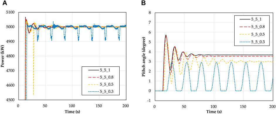
FIGURE 3. Comparison of effects of flap-wise stiffness on power and pitch angle.
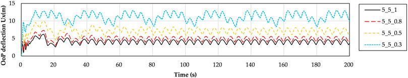
FIGURE 4. Comparison of effects of flap-wise stiffness on tip out-of-plane displacement.
SAF (Sensitivity Analysis Factor) is used to quantitatively analyze the influence of each stiffness coefficient on the physical quantity of root moment. SAF is defined as follows:
where
Figure 5 shows the sensitivity of the main diagonal stiffness to the root moment. The number of the legend indicates the position of the stiffness parameter in the stiffness matrix, for instance, ‘4_3’ of the legend is the stiffness coefficient of the fourth row and the third column in the stiffness matrix. It can be seen from Figure 5A that
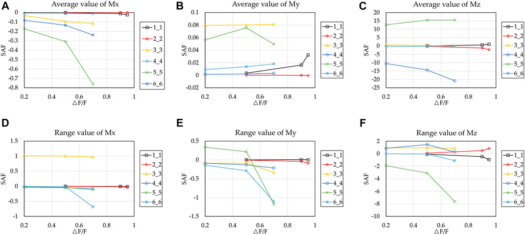
FIGURE 5. Sensitivity of main diagonal stiffness to blade root moment.
It can be seen from Figure 5B that all main diagonal coefficients have low sensitivity to the mean value of blade root moment My. For the range of My,
As can be seen from Figure 5C,F that the average of Mz is very sensitive to
Figure 6 shows the sensitivity coefficient of non-main diagonal stiffness to blade root moment. It can be seen from Figure 6A,D that
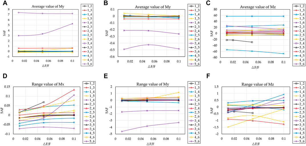
FIGURE 6. Sensitivity of non-main diagonal stiffness to blade root moment.
As can be seen from Figure 6B,E,
For the mean value of root Mz, except
Simulation Analysis Results of Turbulent Wind Condition
In order to analyze the simulation results under the condition of turbulent wind, Mann (Mann, 1994) uniform shear model is used. The representative value of the turbulence standard deviation
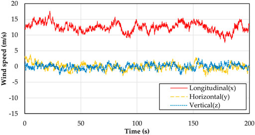
FIGURE 7. Wind speed of turbulent wind condition.
The aeroelastic responses of the wind turbine are analyzed by using the simulation analysis method and stiffness adjustment strategy in Model description. Taking the flap-wise stiffness as an example, the comparison results of pitch angle, blade root moment My, and blade tip displacement Ux are shown in Figure 8A shows the adjustment of blade pitch angle to ensure stable power output. It can be seen that the rated power cannot be reached even if the pitch angle is adjusted to 0° in the simulation time of 90 s and 170–180 s. But it does not affect the sensitivity research. It also can be seen from Figure 8 that the flap-wise stiffness has an obvious effect on the bending moment and deformation of the blade. In order to quantify the degree of impact, the SAF factor is also introduced to analyze the sensitivity under turbulent wind conditions.
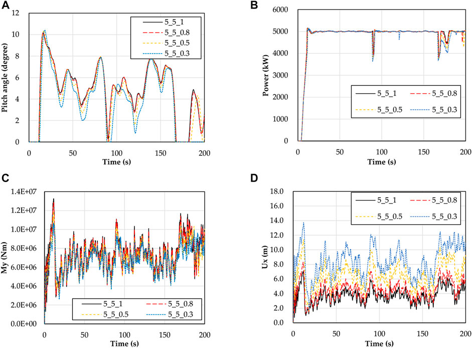
FIGURE 8. The aeroelastic response of the models with flap-wise stiffness adjusted.
In the case of turbulent wind conditions, the extreme values of blade root moment and tip deformation are taken as the objects for sensitivity analysis. The sensitivity factor of the stiffness coefficient of the main diagonal and non-main diagonal are shown in Figure 9 and Figure 10. The results show that
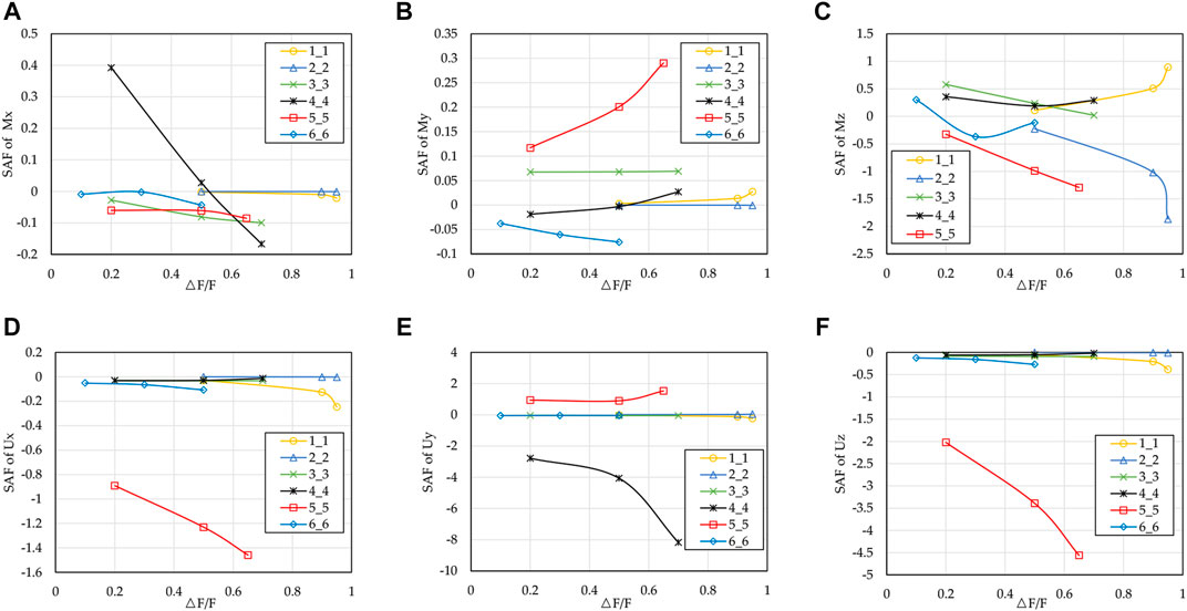
FIGURE 9. Influence of main diagonal stiffness coefficient on medium and high sensitivity.
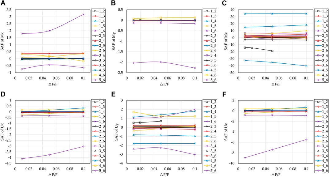
FIGURE 10. Influence of non-main diagonal stiffness coefficient on medium and high sensitivity.
It can be seen from Figure 10 that
Conclusion
The influence of blade beam section stiffness coefficients on wind turbine aeroelastic responses is studied by the aeroelastic analysis method based on the aeroelastic analysis module and nonlinear beam theory. The aeroelastic analysis module is Aerodyn based on the BEM theory, and the nonlinear beam theory is GEBT. The section stiffness of the blade is a complete stiffness matrix based on the generalized Timoshenko beam theory. As the flap-wise stiffness in the matrix is one of the most important stiffness in the blade design, the flap-wise stiffness of the baseline model is used as the reference to adjust the stiffness coefficients. By adjusting the single stiffness coefficient while other conditions remain unchanged, the aeroelastic response analysis is carried out. Finally, the sensitivity analysis coefficient is used for quantitative comparison and the aeroelastic simulation results are compared. The conclusions are as follows:
a. The sensitivity analysis results of turbulent and steady wind conditions are basically consistent, but the sensitivity of turbulent wind conditions is generally lower than that of steady wind conditions.
b. The deformation of the blade has an obvious influence on the power output of the wind turbine. The main reason is that the swept area of the wind turbine is reduced due to the deformation of the blade, which is not enough to capture enough wind energy. Even if the pitch angle is adjusted, the power output is still unstable.
c. The main diagonal coefficients, which are more sensitive to the root moment Mx (medium and high sensitivity), are
d. All main diagonal coefficients are positively sensitive to the mean value of My and are not sensitive. For the range value of blade root moment My, excluding the case of power generation not reaching the rated power, the changes of
e. For blade root moment Mz,
f. The non-diagonal coefficients
The load of wind turbines has a direct impact on the structural design of wind turbines. The work of this paper gives the sensitivity analysis method and results of the blade stiffness to the aeroelastic response of wind turbine under certain conditions, which is helpful to improve the understanding of the coupling effect between structure and load and to provide some guidance for the direction of structural adjustment in blade optimization design.
Data Availability Statement
The original contributions presented in the study are included in the article/supplementary material, further inquiries can be directed to the corresponding author.
Author Contributions
CC performed the calculations and tests and wrote the manuscript. LW checked the calculation results, and TW helped analyze the results. All authors have read and agreed to the published version of the manuscript.
Funding
This study was funded by the National Key R&D Program of China (Grant no. 2019YFB1503701), the National Nature Science Foundation of China (Grant nos. 51506089 and 51761165022), and the Priority Academic Program Development of Jiangsu Higher Education Institutions.
Conflict of Interest
The authors declare that the research was conducted in the absence of any commercial or financial relationships that could be construed as a potential conflict of interest.
Publisher’s Note
All claims expressed in this article are solely those of the authors and do not necessarily represent those of their affiliated organizations, or those of the publisher, the editors and the reviewers. Any product that may be evaluated in this article, or claim that may be made by its manufacturer, is not guaranteed or endorsed by the publisher.
References
Ahlström, A. (2006). Influence of wind turbine flexibility on loads and power production. Wind Energ. 9, 237–249. doi:10.1002/we.167
Ashwill, T., Kanaby, G., Jackson, K., and Zuteck, M. (2010). “Development of the sweep-twist adaptive rotor (STAR) blade,” in 48th AIAA Aerospace Sciences Meeting Including the New Horizons Forum and Aerospace Exposition (Orlando, Florida: AIAA Press), 1582. doi:10.2514/6.2010-1582
Berdichevskii, V. L. (1979). Variational-asymptotic method of constructing a theory of shells. J. Appl. Math. Mech. 43, 711–736. doi:10.1016/0021-8928(79)90157-6
Buhl, M. L. J. (2005). New empirical relationship between thrust coefficient and induction factor for the turbulent windmill state. Golden, CO (United States): National Renewable Energy Lab.(NREL). doi:10.2172/15016819
Chaviaropoulos, P. K., and Hansen, M. O. L. (2000). Investigating Three-Dimensional and Rotational Effects on Wind Turbine Blades by Means of a Quasi-3D Navier-Stokes Solver. J. Fluids Eng. 122, 330–336. doi:10.1115/1.483261
Corrigan, J. J., and Schillings, J. J. (1994). Emprical Model for Stall Delay Due to Rotation. American Helicopter Society Aeromechanics Specialists Conference San Francisco, CA: NASA Press.
Du, Z., and Selig, M. (1998). “A 3-D stall-delay model for horizontal axis wind turbine performance prediction,” in 1998 ASME Wind Energy Symposium (Reno, NV: AIAA Press). doi:10.2514/6.1998-21
Elgammi, M., and Sant, T. (2017). A new stall delay algorithm for predicting the aerodynamics loads on wind turbine blades for axial and yawed conditions. Wind Energy 20, 1645–1663. doi:10.1002/we.2115
Gebhardt, C. G., and Roccia, B. A. (2014). Non-linear aeroelasticity: an approach to compute the response of three-blade large-scale horizontal-axis wind turbines. Renew. Energ. 66, 495–514. doi:10.1016/j.renene.2013.12.040
Glauert, H. (1935). “Airplane Propellers,” in Aerodynamic Theory: A General Review of Progress Under a Grant of the Guggenheim Fund for the Promotion of Aeronautics (Berlin, Heidelberg: Springer Berlin Heidelberg), 169–360. doi:10.1007/978-3-642-91487-4_3
Glauert, H. (1926). The analysis of experimental results in the wind mill brake and vortex ring states of an air screw. London: HM Stationery Office.
Gozcu, M. O., Olgun, M. N., and Kayran, A. (2014). “Investigation of the effect of off-axis spar cap plies on damage equivalent loads in wind turbines with superelement blade definition,” in 32nd ASME Wind Energy Symposium (National Harbor, Maryland: AIAA Press), 1223. doi:10.2514/6.2014-1223
Guntur, S., Sørensen, N. N., Schreck, S., and Bergami, L. (2016). Modeling dynamic stall on wind turbine blades under rotationally augmented flow fields. Wind Energy, 19, 383–397. doi:10.1002/we.1839
Hayat, K., and Ha, S. K. (2015). Load mitigation of wind turbine blade by aeroelastic tailoring via unbalanced laminates composites. Compos. Structures 128, 122–133. doi:10.1016/j.compstruct.2015.03.042
Hodges, D. H. (1990). A mixed variational formulation based on exact intrinsic equations for dynamics of moving beams. Int. J. Sol. Structures 26, 1253–1273. doi:10.1016/0020-7683(90)90060-9
Jonkman, J., Butterfield, S., Musial, W., and Scott, G. (2009). Definition of a 5-MW reference wind turbine for offshore system development. Golden, CO (United States): National Renewable Energy Lab.(NREL). doi:10.2172/947422
Kim, T., Hansen, A. M., and Branner, K. (2013). Development of an anisotropic beam finite element for composite wind turbine blades in multibody system. Renew. Energ. 59, 172–183. doi:10.1016/j.renene.2013.03.033
Larsen, T. J., Hansen, A. M., and Buhl, T. (2004). “Aeroelastic effects of large blade deflections for wind turbines,” in Special topic conference: The science of making torque from wind (Netherlands: Delft University of Technology), 238–246. ISBN: 90-76468-10-9.
Larwood, S., Van Dam, C. P., and Schow, D. (2014). Design studies of swept wind turbine blades. Renew. Energ. 71, 563–571. doi:10.1016/j.renene.2014.05.050
Leishman, J. G., and Beddoes, T. S. (1989). A Semi‐Empirical Model for Dynamic Stall. J Am. Helicopter Soc. 34 (3), 3–17. doi:10.4050/JAHS.34.3.3
Lobitz, D., and Veers, P. (1998). “Aeroelastic behavior of twist-coupled HAWT blades,” in 1998 ASME Wind Energy Symposium (Reno, NV: AIAA Press), 29. doi:10.2514/6.1998-29
Mann, J. (1994). The spatial structure of neutral atmospheric surface-layer turbulence. J. Fluid Mech. 273, 141–168. doi:10.1017/s0022112094001886
Manwell, J. F., Mcgowan, J. G., and Rogers, A. L. (2009). Wind Energy Explained: Theory, Design and Application. New Jersey, United States: John Wiley & Sons. doi:10.1002/0470846127
Pitt, D. M., and Peters, D. A. (1980). Theoretical prediction of dynamic-inflow derivatives. Vertica 5 (1), 21–34.
Ponta, F. L., Otero, A. D., Lugo, L. I., and Rajan, A. (2016). Effects of rotor deformation in wind-turbine performance: The Dynamic Rotor Deformation Blade Element Momentum model (DRD-BEM). Renew. Energ. 92, 157–170. doi:10.1016/j.renene.2016.01.098
Tongguang Wang, W. Z., and Qian., Yaoru. (2019). Calculation method of wind turbine aerodynamic (in chinese). Beijing: Science Press. ISBN: 978-7-03-062875-6. doi:10.1109/cac48633.2019.8996244
Vesel, R. W., and McNamara, J. J. (2014). Performance enhancement and load reduction of a 5 MW wind turbine blade. Renew. Energ. 66, 391–401. doi:10.1016/j.renene.2013.12.019
Keywords: wind turbine blade, aeroelastic response, BEM, GEBT, stiffness matrix, sensitivity study
Citation: Chen C, Wang T and Wang L (2021) Sensitivity Study of the Influence of Blade Sectional Stiffness Parameters on the Aeroelastic Response of Wind Turbines. Front. Energy Res. 9:707082. doi: 10.3389/fenrg.2021.707082
Received: 08 May 2021; Accepted: 21 June 2021;
Published: 11 August 2021.
Edited by:
Wei Jun Zhu, Yangzhou University, ChinaCopyright © 2021 Chen, Wang and Wang. This is an open-access article distributed under the terms of the Creative Commons Attribution License (CC BY). The use, distribution or reproduction in other forums is permitted, provided the original author(s) and the copyright owner(s) are credited and that the original publication in this journal is cited, in accordance with accepted academic practice. No use, distribution or reproduction is permitted which does not comply with these terms.
*Correspondence: Tongguang Wang, tgwang@nuaa.edu.cn