Structured Light Control and Diagnostics Using Optical Crystals
 O. V. Angelsky
 A. Y. Bekshaev
 G. S. Dragan
 P. P. Maksimyak2
  C. Yu. Zenkova
 Jun Zheng
- 1Research Institute of Zhejiang University-Taizhou, Taizhou, China
- 2Chernivtsi National University, Chernivtsi, Ukraine
- 3Physics Research Institute, Odessa I.I. Mechnikov National University, Odessa, Ukraine
We describe experimental results exposing the possibilities of optical crystals, especially anisotropic and birefringent, for creation, control, and diagnostics of structured light fields with singular and extraordinary properties. The efficiency of birefringent media is demonstrated for purposeful generation of optical beams with phase singularities (optical vortices) and desirable patterns of internal energy flows, in both the mono- and polychromatic light. On the other hand, anisotropic micro-objects can be used as probing bodies for investigation of the peculiar features of internal energy flows and corresponding momentum and angular momentum distributions in structured light fields. In particular, the specific mechanical action of light fields, formed under the total-reflection conditions, has been detected that confirms the existence of “extraordinary” dynamical characteristics of evanescent light waves predicted theoretically: the “transverse” momentum and “vertical” spin and their dependence on the incident beam polarization. The results can be useful for the optical trapping and micromanipulation techniques, including the biomedical and pharmaceutical applications.
Introduction
Comprehensive studies of optical fields, especially intensive in recent decades, have enriched our understanding of the internal nature of structured light [1, 2] and discover new possibilities associated with the internal optical energy flows and three-dimensional polarization distribution of light beams. This enabled additional advance in the creation of optical means for trapping and controllable transportation of micro- and nano-objects (optical tweezers and spanners, micromachines, etc. [3–5]) as well as in the implementation of micro- and nano-precision measurements.
In these applications, an important role belongs to the dynamical characteristic of light fields [1, 6] associated with the spatial distributions of their energy density
and the energy flow density (Poynting vector)
where E and H are the complex amplitudes of the electric and magnetic vectors
where R is the spatial radius-vector. In turn, the optical momentum density (Eq. 3) can be written as [1, 6]
where
and
represent the orbital (“canonical”) and spin (“virtual”) parts of the total field momentum. Accordingly, due to the relations between p and S (Eq. 2, Eq. 3), the “orbital” and “spin” constituents of the energy flow (Eq. 2) are also defined by the expressions in Eq. 6, Eq. 7. The immediate formal sense of the momentum decomposition (Eqs 5–7) is that
while the orbital AM expression follows immediately from the definition (Eq. 4),
The description, properties, and diagnostics of these characteristics are discussed in a number of works [2, 3, 6–8]. In particular, it has been shown that the orbital and spin AMs of a focused light beam can cause orbital and spinning rotational motions of captured micro- and nano-objects. Depending on the momentum direction and on the sense of internal energy circulation [3, 4, 6, 9], the direction and other parameters of the object’s rotation change.
Of particular interest are optically anisotropic, for example, birefringent objects, for which the mechanical action of circularly polarized light is the most spectacular [9–11] and for which the existence of the AM of light was demonstrated for the first time [12]. The possibilities to capture a micro-object and the character of the field-induced motion depend on the optical properties, internal structure, external shape of the object, its position within the incident beam, and, naturally, beam polarization. For example, the direction of the object rotation is determined by the polarization handedness, while the rotation velocity is proportional to the beam power [10]. The mechanisms of transfer of the internal energy circulation with distributed spin and orbital AMs to birefringent objects have been comprehensively studied [13, 14]. These investigations show how the interaction between an optical beam with AM and an anisotropic object of regular shape can serve to extracting information about both the beam and the object [14]. At the same time, the interaction of light with irregularly shaped optically anisotropic micro-objects is not perfectly clear, although approaches are known that give reliable qualitative estimations for the applied torque and force [13]. This enables obtaining information about the internal structure of the beam, and on the other hand, using an optical beam with an internal AM, it is possible to evaluate the shape and size of such objects.
Linear light-induced motion of particles is determined by the field momentum (Eq. 3), (Eq. 5) [6, 15] whose orbital (Eq. 6) and spin (Eq. 7) parts differently act on material objects [16]. The orbital-momentum action can be associated with the usual optical pressure [17], while the SM “motivates” particles in a more complicated manner (e.g., non-collinearly with the momentum direction [16]). The very existence of the SM-induced mechanical action was largely questionable until it has been explicitly demonstrated in experiments with spatially inhomogeneous circularly polarized beams [18, 19].
The polarization-dependent SM is also typical for the evanescent waves [8, 20]. In case when the evanescent wave is formed in the process of total internal reflection from the prism surface, the SM direction is determined by input beam polarization. The experimental observation of this “extraordinary” SM [8] in evanescent waves requires a more exquisite technique [21] than that was used in the case of paraxial beams [18, 19], but it has also been demonstrated with the help of anisotropic birefringent objects [22, 23]. The unique peculiarity of these demonstrations was the micro-object’s motion in a direction different from the Poynting-vector direction.
Simultaneously, optical crystals with birefringence not only are able to react on structured light but also have a great potential in the generation of complex light fields with desirable patterns of internal dynamical characteristics (Eqs 1–8). In this work, the experimental results are presented that demonstrate capabilities of optically anisotropic crystals in the light structures’ formation and testing, and their possible applications are discussed.
Creation of Structured Optical Fields With the Use of Biaxial Crystals
Biaxial crystals are one of the most promising elements for creating singularities of different types and properties. The use of these crystals for the formation of optical fields with singularities is possible in both monochromatic [24–26] and polychromatic fields. Singularities in polychromatic fields can be employed to implement polychromatic optical traps, whose spatial structure can be tested with high sensitivity and resolution due to the interference approaches.
In one of the previous works [27], we proposed the film of polyethylene terephthalate (PETP) having the properties of a biaxial crystal (thickness 74 μm, difference of refraction indices 0.085) as an anisotropic phase element providing a large phase variance. It was used for producing and identification of optical singularities in white light (Figure 1).
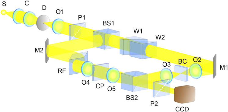
FIGURE 1. Experimental arrangement for generation of white-light optical vortices: (S) white-light source; (C) condenser; (D) diaphragm; (O1, O2, O3, O4, and O5) objective lenses; (P1 and P2) polarizer and analyzer; (BS1 and BS2) beam-splitting cubes; (M1 and M2) mirrors; (BC) singularity-generating object; (CP) compensating plate; (RF) Fresnel rhombus; (W1 and W2) moving and stationary optical wedges; (CCD) camera.
The object is placed in the converging beam between the objectives O2 and O3. To facilitate identical chromatic and aberration conditions in the legs of an interferometer, the objectives O4 and O5, which are identical to the objectives O2 and O3, and the compensating plate CP in between are placed in the second leg of the interferometer. The Fresnel rhombus RF, providing circular polarization for all spectral components of white light, is placed in the second leg. To geometrically compensate the beam displacements inside the Fresnel rhombus, two optical wedges W1 and W2 forming a plane-parallel plate are inserted in the other arm. The shift of the wedge W1 along its hypotenuse enables control of the plate thickness and, as a consequence, of the optical path difference in the legs of the interferometer. The interferometer output is followed by an analyzer P2 and a CCD camera. The objectives O3 and O5 can synchronically be moved along the direction of propagation of the beams providing equal convergence. The angle of interference in the interferometer is controlled by transverse displacement of the objective O5.
Results of the interference diagnostics of the white-light singularities obtained with the help of a biaxial crystal are presented in Figure 2. In Figure 2A, the singularities look as the suspected amplitude zeros, but one cannot be confident that these are not just the intensity minima. As is known [28], a genuine optical-vortex singularity is characterized by the helical phase distribution (phase dislocation) which can be revealed through interference with a non-singular light beam. Figure 2B shows that this approach, widely used for monochromatic light, is equally valid for polychromatic fields.
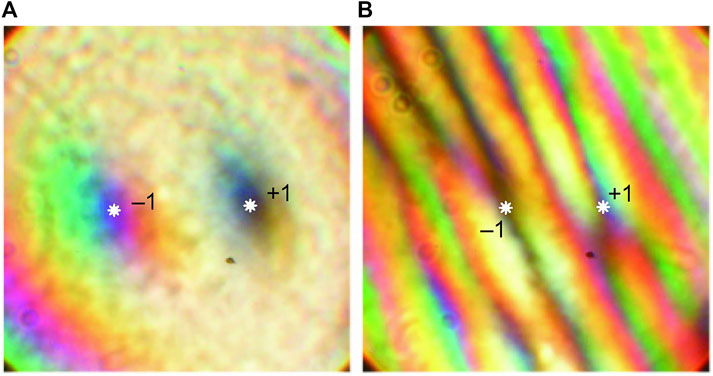
FIGURE 2. Singularities obtained in a white-light beam after passing a biaxial crystal placed between the matched polarizer P1 and the analyzer P2 (see Figure 1): (A) without reference wave; (B) with a reference wave [27]. The topological charges are indicated of the two singularities with exact locations marked by asterisks.
It illustrates the detection of singularities obtained when a white-light beam propagates along either of the two optical axes of a biaxial crystal placed between the matched polarizer P1 and analyzer P2 (Figure 1). The zeros of amplitude are detected by the “forks” in the interference pattern, cf. Figures 2A,B. In the case of a white-light vortex [27], the interference forks are achromatic, but the amplitude zeros for all spectral components coincide in localization. The shape and orientation of the forks enables determining the singularity characteristics: the phase-dislocation charge and its sign [28] (±1 in Figure 2).
The results in [27] testify that the biaxial crystals can generate optical fields with a rich singular structure which is generally associated with the rich and flexible pattern of internal energy flows (Eqs 3–7) [6]. This possibility, revealed and substantiated in experiments, has inspired further research aiming at the purposeful creation of the momentum and energy flow distributions, favorable for particle manipulation, in the monochromatic light [29].
For example, in the arrangement of Figure 3, the slightly convergent (conical) light beam with prescribed linear polarization is used, which, after passing the optically anisotropic plate (7), forms the complex structured light field with spatially inhomogeneous distributions of the amplitude, phase, and polarization. In this scheme, the dichroic cube (12) fully reflects the laser beam, and the 40× microlens (13) focuses it onto the sample plane (14) containing, e.g., the investigated particles in the immersion fluid. In white light, the sample can be observed with the illuminator (15–16) and the ССD camera (18). A small part of the laser beam power (∼0.2%) is reflected from the glass substrate and also impinges the ССD camera, connected to the PC (19), which enables observing the structure formed in the laser beam. Additionally, the PC performs control of the 3D drives regulating positions of the calcite wedges (10) and the biaxial plate (7). The wedges (10) and the polarizer (11) form a polarization shear interferometer enabling efficient control of the output beam structure even in white light, due to the calcite plate (9), which compensates for the path difference between the orthogonally polarized components.
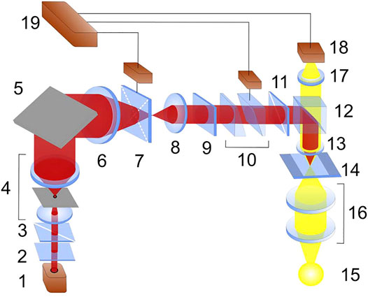
FIGURE 3. Optical arrangement of tweezers based on a birefringent crystal: (1) laser; (2) quarter-wave plate; (3, 11) polarizers; (4) beam expander with spatial filtering; (5) mirror; (6, 8, 13, and 17) micro-objectives; (7) biaxial crystal with a 3D rotating drive; (9) calcite plate; (10) calcite wedges with 2D shifting of one wedge; (12) beam-splitting dichroic cube; (14) sample; (15) white-light source for illumination; (16) condenser lenses; (18) CCD camera; (19) PC.
In such fields, in addition to classical phase singularities [1, 2, 6, 28], one can detect a set of polarization singularities [1] with accompanying internal energy flows enabling efficient control and manipulation of the trapped objects (see Figure 4). In particular,
a) the intensity minima (maxima) naturally form transverse optical traps for absorptive (dielectric) particles due to the gradient optical forces [15, 16];
b) phase singularities localized at the amplitude zeros (Figure 4A) are coupled with the vortex-like orbital flows (Eq. 6) [1, 6, 28], which can cause orbital or spinning rotation of trapped particles;
c) both the orbital momentum (Eq. 6) and the SM (Eq. 7) are able to induce the directional motion of particles within the transverse plane XY (Figures 4A,B);
d) the spin AM density (Eq. 8) (Figure 4B) can induce the controllable rotational (spinning) motion depending on its position within the beam cross section.
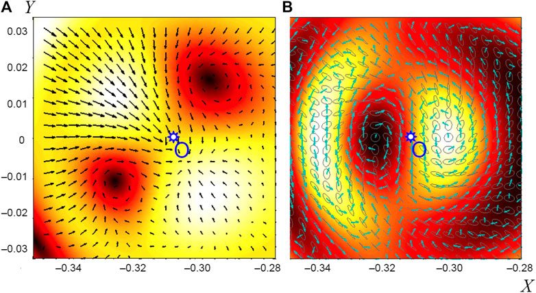
FIGURE 4. Field distributions at the biaxial crystal output in the vicinity of the optical axis O (both optical axes lie in the plane XZ so that x = 0 corresponds to the middle direction between the axes); the input beam polarization makes an angle 45° with the axis X: (A) intensity distribution after the output X-oriented polarizer (background) and the transverse orbital flow (Eq. 6) component of the X-polarized component (black arrows); (B) spin density (Eq. 8) of the total output field (background), spin flow (Eq. 7) map (cyan arrows), and polarization distribution (gray ellipses) [29].
The optical field structure formed after passing the crystal depends on the incident beam polarization determined by the input polarizer (3) and can be adjusted by the output polarizer (11), which enables suitable ways for field regulation and for precise spatial localization of the trapped particles. Figure 4 shows examples of the field structures obtained in the arrangement of Figure 3 for different conditions. Eigen refractive indices of the biaxial crystal (7, see Figure 3) are nx = 1.54, ny = 1.57, and nz = 1.64; the crystal thickness (length in the z-direction) equals 74 μm. The dimensionless coordinates X and Y are associated with the stereographic projection of the spherical angular frame (θ, ϕ) [31] centered at the common focal point of lenses 6 and 8 (Figure 3):
Here, f is the focal distance of lens 8 in Figure 3.
Figure 5 demonstrates transformations of the output field containing a set of optical traps (amplitude zeros) and corresponding possibilities for spatial manipulation of the particles trapped. The images (Figures 5A–H) show consecutive beam patterns realized during the translation of one of the wedges (10) across the propagation axis (see Figure 3). One can see the convergence of the traps up to their merging (Figures 5A–E), and subsequent divergence of them (Figures 5F–H). In this process, additional traps (intensity minima) can be obtained (Figures 5D–G), providing additional possibilities for purposeful guiding and arrangement of the particles trapped.
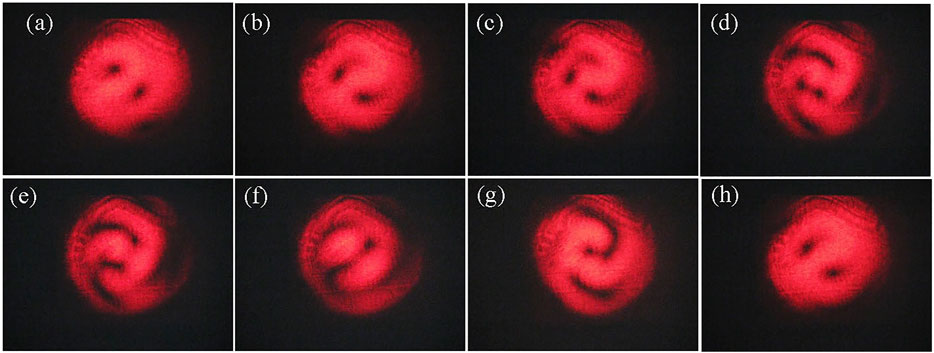
FIGURE 5. Illustration of the different sorts of optical traps created by means of the birefringent crystal and their transformations in the arrangement of Figure 3 [29]. Images (a–h) represent the field patterns realized by proper adjustment of the optical system (explanations in the text).
The data presented testify that observations of the mechanical motions of particles trapped in complex structured fields can give valuable information on the field properties and, especially, on the distribution of internal energy flows [6, 9, 10, 30]. On the other hand, micro- and nano-objects with various optical properties (refractive index, external shape, and internal structure) differently react on the ponderomotive factors of the light field. This fact is favorable for detection and analysis of various microscopic objects, even at ultra-small concentrations, up to solitary examples of some active species.
Investigations of Optical Surface Phenomena and Evanescent Fields
Evanescent optical waves represent a special sort of structured light fields with exclusive “extraordinary” properties [8, 20]. Such fields usually appear in the process of total reflection when an incident plane wave approaches the boundary between two media with different optical constants (Figure 6). If the condition
where the subscripts “||” and “⊥” denote the polarization parallel (p-) and orthogonal (s-) to the plane of incidence (Figure 6). The three coordinate frames are introduced in Figure 6 associated with the incident (x1, y, z1), reflected (xr, y, zr), and transmitted (x, y, z) beams; the reflecting boundary lies in the plane z = 0, all three origins coincide, and the axis y, normal to the plane of incidence, is the same for all frames. Let the incident wave electric vector equal
its state of polarization is characterized by the complex parameter
(τ = ±1 means s- or p-polarization, χ = ±1 means ±45°-polarization, and σ = ±1 means right/left circular polarization). The evanescent wave characteristics in medium 2 are determined by the elements of tensor
Likewise, the field in medium 1 is determined by the reflection tensor
the field energy flow and momentum (Eq. 3) acquire the “extraordinary” transverse contributions associated with the SM (Eq. 7):
where ε1 and ε are the permittivities of media 1 and 2,
is the incident wave intensity. Similarly, in the system of Figure 6, the spin density (Eq. 8) also possesses the unusual “transverse” (y-) and “vertical” (z-) components [32, 33]:
Equations (Eqs 14, 15) determine the transverse force acting on a small dipolar particle [8, 16], and Eqs. 19–22 determine the extraordinary torques. Note that the total vertical electromagnetic spin (Eq. 22) of the evanescent wave vanishes, but it consists of the non-zero “electric”
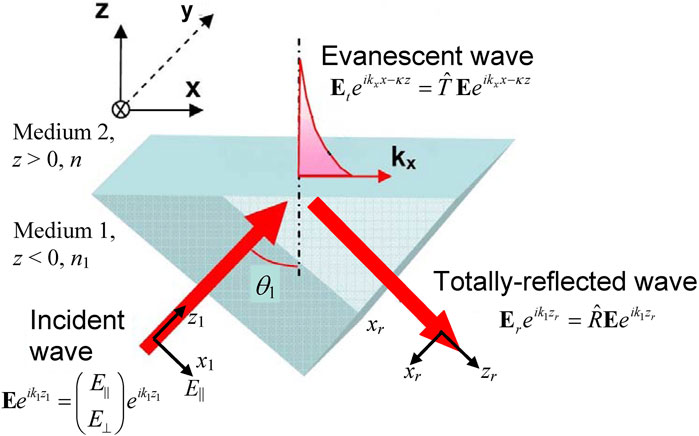
FIGURE 6. Illustration of the evanescent wave formation (explanations in the text).
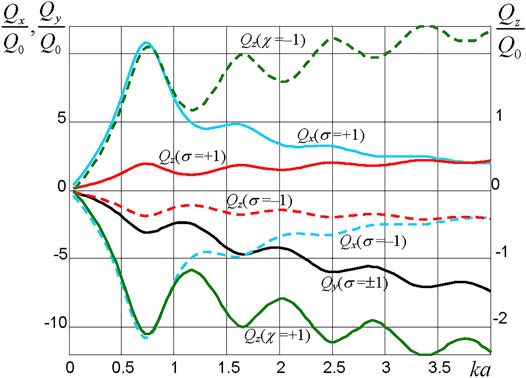
FIGURE 7. Normalized radiation torque Q components vs the particle size parameter, ka, calculated for the gold particle situated on the surface of the glass prism (n1 = 1.75) in water at λ = 650 nm when the incident wave with λ = 650 nm approaches the surface at an angle θ1 = 51°: longitudinal x-component, circular polarization (cyan curves, left scale); transverse y-component, circular polarization (black curve, left scale); vertical z-torque, circular polarization (red curves, right scale); vertical z-torque, 45°-polarization (green curves, right scale).
The detailed picture of the optical forces and torques experienced by a Mie particle in the evanescent wave has been discussed in Ref. [32]; here, we are restricted to the field-induced torque and its dependence on the incident beam polarization parameters (Eq. 10). For numerical evaluations, we assume [34] that a spherical particle of radius
which is proportional to the time-average momentum flux through the area a2 within the field of the incident plane wave (see Figure 6) approaching the interface.
The results of the torque calculations are presented in Figure 7. Despite the complicated dependence on the particle size associated with the intrinsic plasmon resonances in the particle, they remarkably confirm the general features of the polarization dependence predicted by the spin equations (Eqs. 18, 20, 22). It is noteworthy that the torques Qx and Qz change the sign when switching the polarization handedness (σ = ±1) or the direction of polarization-plane 45°-inclination (χ = ±1), in full agreement with the sx and sz expressions (Eq. 18) and (Eq. 22), whereas Qy remains the same—according to Eqs. 19, 20, the corresponding ponderomotive factor sy depends solely on the “x–y” polarization parameter τ (Eq. 10).
In view of the fundamental interest to the evanescent field mechanical action, many efforts have been directed to the experimental confirmation of the forces and torques predicted by Eqs. 12–22 [21, 36]. However, reliable quantification of the spinning motion of spherical particles in the evanescent wave, where the particle center is not fixed in the horizontal plane, is a difficult task [37], and for this reason, another way for the vertical spin detection has been proposed. Instead of the Mie particles, it uses the crystalline microplate as a probing body [22].
In this scheme (see Figure 8), the 200 × 200 × 9 μm3 PETP plate 4 is floating over the water layer, and the incident beam parameters are adjusted such that the incident wave experiences the total reflection at the upper surface of plate 4 and approaches it being linearly polarized at 45° (in Eq. 10, τ = σ = 0, |χ| = 1). The incident beam is formed by the IR laser radiation (wavelength 980 nm) focused into a focal spot of size ∼50 × 50 μm2 (see Figure 9). As a result, an evanescent wave is formed in air above the plate, and the electromagnetic momentum and spin on both sides of the upper plate surface can be described by Eqs. 12–22. Especially the vertical spin momentum sz with the homogeneous density (Eq. 21) is generated inside the plate.
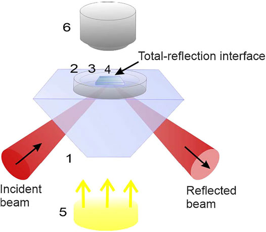
FIGURE 8. Experimental arrangement for the vertical spin detection: (1) glass cut rectangular prism (refraction index equals 1.52); (2) 2-mm-height ring cuvette; (3) water layer; (4) crystalline plate; (5) white-light illuminating source; (6) CCD camera.
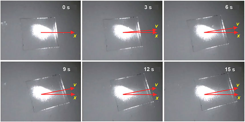
FIGURE 9. Rotation and rectilinear motion of plate 4 (see Figure 8) induced by a 1 W-power incident laser beam impinging the plate at an angle of 58°. The bright spot is the “trace” of the incident beam impinging the plate.
Since the incident light field carries no AM before it enters plate 4, the AM conservation requires that the plate itself experiences the “recoil” mechanical AM inducing the plate rotation around a vertical axis. This rotation, observed in the experiment (see Figure 9), qualitatively confirms the existence of the spin AM (Eq. 21) inside the plate, which, although indirectly, testifies for the vertical spin (Eq. 22) in the evanescent wave. Note that this ideology is close to the idea of the first experimental demonstration of the electromagnetic AM [12]: the main difference is that the optical anisotropy, necessary for the AM transformation inside a crystalline medium in [12], is now supplied by the oblique incidence of the input light beam, and the light back-propagation is realized via the total-reflection mechanism rather than due to a special reflecting mirror.
In this scheme, the result is rather sensitive to the angle of incidence θ1 at which the input beam approaches the plate bottom surface (see Figures 6, 8). Experimentally, the best results were obtained when θ1 = 58°, and the effect rapidly vanished with any deviation from this value. This can be explained by the reasoning that, for lower θ1, the reflection from the upper face is not total and phases of the reflection coefficients R|| and R⊥ are close to each other, which leads to a decrease of the vertical spin density (Eq. 21) inside the plate; on the contrary, with growing θ1 > 58°, the reflection at the bottom face grows and the light penetration into the plate decreases.
Figure 9 shows a series of consecutive plate positions registered by the CCD camera (6) of Figure 8 [22] (time elapsed after the laser power is turned on is indicated in each image). It shows not only rotation but also a translation so that the plate moves along the vector v different from the longitudinal x-direction. The translational component of the plate motion can be ascribed to the longitudinal (Eq. 12), (Eq. 13) and transverse (Eq. 14), (Eq. 15) momentum components which are also “felt” by the plate. With the translation, the plate’s rotation rate decreases because the bright spot “shifts” from the plate center, and the plate’s moment of inertia with respect to the beam axis grows, while the external torque remains the same or decreases (e.g., when the spot approaches the plate edge and a part of the incident power omits the plate, see the bottom right image of Figure 9).
Spectacular illustrations of the light-induced plate motions in the arrangement of Figure 8 are provided by the three video files presented in the Supplementary Material. In all cases, the incident beam approaches the total-reflection surface at an angle 58°, and the plane of incidence coincides with the coordinate plane (x, z) (the evanescent wave propagates in the x-direction, i.e., along the horizontal axis to the right). Supplementary Video 1 demonstrates additional details of the behavior presented in Figure 9 where the incident beam polarization corresponds to χ = +1 (45°-polarization), whereas Supplementary Video 2 describes the situation of χ = –1 (–45°-polarization). Importantly, the directions of rotation and transverse displacements invert after changing the sign of χ, while the x-directed translation remains the same (cf. Eq. 12, Eq. 14, Eq. 21). On the contrary, in the case of the x-polarized incident beam (σ = χ = 0, Supplementary Video 3), there is no rotation, nor transverse displacement but only the rectilinear horizontal motion, in full agreement with Eqs. 12–15 and Eq. 21, Eq. 22 (a weak rotation observed at the beginning of the motion is explained by uncompensated torques from the optical and hydrodynamic forces).
Additional observations were carried out with the circularly polarized incident beam (τ = χ = 0, σ = ±1) which have shown qualitatively similar results with quantitative differences stipulated by the specific values of R⊥ and R|| in Eq. 21. The birefringent properties of the PETP plate contribute to increasing the rotation velocity (and thus the vertical spin sensitivity), as compared to other materials. The decisive role of the total-reflection–associated spin and momentum in the observed phenomena is confirmed by experiments with non-transparent materials, e.g., the plate of 7 μm-thickness aluminum foil neither rotated nor moved rectilinearly in the same optical arrangement even for doubled beam intensity (2 W).
Conclusion
In this paper, the special role of optical crystals in the creation and control of structured light is analyzed. In particular, it has been experimentally demonstrated that biaxial crystals are capable of generating multifunctional optical traps with a full set of singularity-forming elements in both polychromatic and monochromatic light. The traps’ parameters are readily controllable and can be adjusted with high precision to perform the particles’ capture, translation, rotation, and delivering in a predictable and convenient way.
Another branch of promising application of optical crystals is based on their specific response to the structured-light influences, which causes their exclusive role as sensitive probing bodies. Their physical and mechanical reactions “bring to light” the “hidden” but important dynamical properties of light fields. Especially, the birefringent crystals and crystal-like structures can be used for manifestation of the near-interface transformations of the electromagnetic momentum and spin, accompanying the total-reflection phenomena. In this context, the motion of floating crystalline microplates enables detection of “extraordinary” transverse momentum and vertical spin inherent in the fields formed on both sides of the totally reflecting interface.
Applied aspects of the research reported in this paper are associated with additional possibilities for optical manipulation, especially in biological and medical applications because many bio-tissues are characterized by the remarkable optical anisotropy [23]. Besides, the highly adaptive and flexible optical traps can be used for controllable delivering and distribution of biologically active species at the cellular and sub-cellular scales. For example, controllable creation and manipulation of micro-bubbles [38], generated in a biological environment, can realize unique mechanical and physico-chemical functions. The collapse of a bubble mechanically affects the surrounding volume, which can be used for desirable agent delivering to special cells in cell surgery and, if necessary, for cell destruction and transfection [39–41]. The ability of bubbles to scatter light makes them suitable micro-objects for imaging cells and tissues.
Such possibilities can be helpful for optical studies of the human coronaviruses [42], including the kind SARS-CoV-2, such topical at present. The coronavirus macromolecules are of spherical shape of 100–140 nm in diameter, with an outer envelope bearing 20 nm-long club-shaped spike proteins [43]; in the visible wavelength range, their refractive index is 1.06, and they are optically anisotropic (the scattering indicatrix is polarization-dependent) [43]. Recent studies related to coronavirus identification in the blood have shown the possibility of various approaches to their investigation [44–46], among which the optical methods can be distinguished, including the fluorescence-based methods, employment of surface plasmons, plasmon-enhanced fluorescence, surface-enhancing Raman scattering, colorimetric biosensor methods [44, 45], and approaches of fiber optics in the nanophotonic framework [46]. Such optical approaches enable detection of the immunoglobulin M and G antibodies or the SARS-CoV-2 molecules themselves.
One of the drawbacks of known methods is insufficient speed of virus detection in the blood with simultaneous assessment of the concentration of immunoglobulin or of the virus molecules themselves. In this context, employment of the structured light fields, described in this work, can be rather promising. The complex influence of light, including inhomogeneities of the intensity, phase, and polarization, performs selective actions on molecules of certain size and optical properties, inducing their purposeful displacements and rotations. Possibilities to analyze the number of trapped molecules simultaneously, as well as the parameters of their photo-induced motions, can supply effective criteria of their presence, concentration, and physical and biological nature.
In conclusion, the complex optical traps, tweezers, and spanners, based on biaxial crystals, as well as allowance for the trapped objects’ anisotropy, open up attractive prospects for biomedicine and engineering. The accompanying possibilities for external control of optical flows and the AM distributions, whenever it is necessary to deal with the smallest amount of a substance, are of vital importance in problems of pharmacology, microbiology, nanophysics, and nanotechnology.
Data Availability Statement
The original contributions presented in the study are included in the article/Supplementary Material, and further inquiries can be directed to the corresponding authors.
Author Contributions
OA, CZ, and PM contributed to conception and design of the study. GD, PM, and JZ organized the database. PM and CZ performed the experiment. CZ wrote the first draft of the manuscript. AB and GD wrote the Introduction. OA, GD, and AB wrote Creation of Structured Optical Fields With the Use of Biaxial Crystals and Investigations of Optical Surface Phenomena and Evanescent Fields. All authors contributed to manuscript revision and read and approved the submitted version.
Funding
This work was supported by the Research Institute of Zhejiang University-Taizhou, Center for Modern Optical Technology, China.
Conflict of Interest
The authors declare that the research was conducted in the absence of any commercial or financial relationships that could be construed as a potential conflict of interest.
Acknowledgments
The authors are grateful to K. Bliokh (RIKEN, Japan) for fruitful discussions.
Supplementary Material
The Supplementary Material for this article can be found online at: https://www.frontiersin.org/articles/10.3389/fphy.2021.715045/full#supplementary-material
References
1. Angelsky OV, Bekshaev AY, Hanson SG, Zenkova CY, Mokhun II, Zheng J. Structured Light: Ideas and Concepts. Front Phys (2020) 8:114. doi:10.3389/fphy.2020.00114
2. Rubinsztein-Dunlop H, Forbes A, Berry MV, Dennis MR, Andrews DL, Mansuripur M, et al. Roadmap on Structured Light. J Opt (2017) 19:013001. doi:10.1088/2040-8978/19/1/013001
3. Nieminen TA, Higuet J, Knoner G, Loke VLY, Parkin S, Singer W, et al. Optically Driven Micromachines: Progress and Prospects. Proc SPIE (2006) 6038:237–45. doi:10.1117/12.651760
4. Dholakia K, Reece P, Gu M. Optical Micromanipulation, Chem Soc Rev (2008) 37:42–55. doi:10.1039/b512471a
5. Padgett M, Bowman R. Tweezers with a Twist. Nat Photon (2011) 5:343–8. doi:10.1038/nphoton.2011.81
6. Bekshaev A, Bliokh KY, Soskin M. Internal Flows and Energy Circulation in Light Beams. J Opt (2011) 13:053001. doi:10.1088/2040-8978/13/5/053001
7. Bliokh KY, Nori F. Transverse and Longitudinal Angular Momenta of Light. Phys Rep (2015) 592:1–38. doi:10.1016/j.physrep.2015.06.003
8. Bliokh KY, Bekshaev AY, Nori F. Extraordinary Momentum and Spin in Evanescent Waves. Nat Commun (2014) 5:3300. doi:10.1038/ncomms4300
9. Dholakia K, MacDonald M, Spalding G. Optical Tweezers: the Next Generation. Phys World (2002) 15:31–5. doi:10.1088/2058-7058/15/10/37
10. Friese MEJ, Nieminen TA, Heckenberg NR, Rubinsztein-Dunlop H. Optical Alignment and Spinning of Laser-Trapped Microscopic Particles. Nature (1998) 394:348–50. doi:10.1038/28566
11. Andrews DL. Structured Light and its Applications: An Introduction to Phase-Structured Beams and Nanoscale Optical Forces. Academic Press (2011). p. 357.
12. Beth RA. Mechanical Detection and Measurement of the Angular Momentum of Light. Phys Rev (1936) 50:115–25. doi:10.1103/PhysRev.50.115
13. Wei Y, Zhu Y, Yao W, Pei H. Rotational Analysis of Birefringent crystal Particles Based on Modified Theory in Optical Tweezers. Proc SPIE (2015) 9522:95220S. doi:10.1117/12.2179434
14. Herne CM, Lyons F, Galvez EJ, Sam A. Polarimetry Studies on Birefringent Materials in Optical Tweezers. Proc SPIE (2020) 11463:1146312. doi:10.1117/12.2567547
15. Dienerowitz M, Mazilu M, Dholakia K. Optical Manipulation of Nanoparticles: a Review. J Nanophoton (2008) 2:021875. doi:10.1117/1.2992045
16. Bekshaev AY. Subwavelength Particles in an Inhomogeneous Light Field: Optical Forces Associated with the Spin and Orbital Energy Flows. J Opt (2013) 15:044004. doi:10.1088/2040-8978/15/4/044004
17. Ashkin A. Optical Trapping and Manipulation of Neutral Particles Using Lasers. World Scientific Publishing Company (2006). p. 940.
18. Angelsky OV, Bekshaev AY, Maksimyak PP, Maksimyak AP, Hanson SG, Zenkova CY. Orbital Rotation without Orbital Angular Momentum: Mechanical Action of the Spin Part of the Internal Energy Flow in Light Beams. Opt Express (2012) 20:3563–71. doi:10.1364/oe.20.003563
19. Angelsky OV, Bekshaev AY, Maksimyak PP, Maksimyak AP, Mokhun , Hanson SG, et al. Circular Motion of Particles Suspended in a Gaussian Beam with Circular Polarization Validates the Spin Part of the Internal Energy Flow. Opt Express (2012) 20:11351–6. doi:10.1364/oe.20.011351
20. Bertolotti M, Sibilia C, Guzman AM. Evanescent Waves in Optics: An Introduction to Plasmonics (Vol. 206). Springer (2017). p. 257.
21. Antognozzi M, Bermingham CR, Harniman RL, Simpson S, Senior J, Hayward R, et al. Direct Measurements of the Extraordinary Optical Momentum and Transverse Spin-dependent Force Using a Nano-Cantilever. Nat Phys (2016) 12:731–5. doi:10.1038/nphys3732
22. Angelsky OV, Hanson SG, Maksimyak PP, Maksimyak AP, Zenkova CY, Polyanskii PV, et al. Influence of Evanescent Wave on Birefringent Microplates. Opt Express (2017) 25:2299–311. doi:10.1364/oe.25.002299
23. Angelsky OV, Zenkova CY, Hanson SG, Zheng J. Extraordinary Manifestation of Evanescent Wave in Biomedical Application. Front Phys (2021) 8:159. doi:10.3389/fphy.2020.00159
24. Angelsky OV, Maksimyak PP. Optical Diagnostics of Slightly Rough Surfaces. Appl Opt (1992) 31:140–3. doi:10.1364/ao.31.000140
25. Angelsky OV, Maksimyak PP, Magun II, Perun TO. On Spatial Stochastization of Optical fields and Feasibilities of Optical Diagnostics of Objects with Large Phase Inhomogeneities. Opt Spectr (1991) 71:123–8.
26. Angelsky OV, Maksimyak PP. Polarization-interference Measurement of Phase-Inhomogeneous Objects. Appl Opt (1992) 31(22):4417–9. doi:10.1364/ao.31.004417
27. Angelsky OV, Maksimyak AP, Maksimyak PP, Hanson SG. Interference Diagnostics of white-light Vortices. Opt Express (2005) 13:8179–83. doi:10.1364/opex.13.008179
28. Soskin MS, Vasnetsov MV. Singular Optics. Prog Opt (2001) 42:219–76. doi:10.1016/s0079-6638(01)80018-4
29. Angelsky OV, Bekshaev AY, Maksimyak PP, Polyanskii PV. Internal Energy Flows and Optical Trapping. Opt Photon News (2014) 25(12):20–1.
30. Angelsky OV, Maksymyak PP, Zenkova CY, Hanson SG, Zheng J. Current Trends in Development of Optical Metrology. Opt Mem Neural Networks (2020) 29(4):269–92. doi:10.3103/s1060992x20040025
31. Berry M, Bhandari R, Klein S. Black Plastic Sandwiches Demonstrating Biaxial Optical Anisotropy. Eur J Phys (1999) 20:1–14. doi:10.1088/0143-0807/20/1/001
32. Bekshaev A. Abraham-based Momentum and Spin of Optical fields under Conditions of Total Reflection. ArXiv preprint. arXiv:1710.01561 [physics.optics] (2017).
33. Bekshaev AY. Dynamical Characteristics of an Electromagnetic Field under Conditions of Total Reflection. J Opt (2018) 20:045604. doi:10.1088/2040-8986/aab035
34. Bekshaev AY, Bliokh KY, Nori F. Mie Scattering and Optical Forces from Evanescent fields: A Complex-Angle Approach. Opt Express (2013) 21:7082–95. doi:10.1364/oe.21.007082
36. Liu L, Kheifets S, Ginis V, Di Donato A, Capasso F. Elliptical Orbits of Microspheres in an Evanescent Field. Proc Natl Acad Sci USA (2017) 114(42):11087–91. doi:10.1073/pnas.1714953114
37. Angelsky OV, Bekshaev AY, Maksimyak PP, Maksimyak AP, Hanson SG. Measurement of Small Light Absorption in Microparticles by Means of Optically Induced Rotation. Opt Express (2015) 23:7152–63. doi:10.1364/oe.23.007152
38. Angelsky OV, Bekshaev AY, Maksimyak PP, Maksimyak AP, Hanson SG, Kontush SM. Controllable Generation and Manipulation of Micro-bubbles in Water with Absorptive Colloid Particles by CW Laser Radiation. Opt Express (2017) 25:5232–43. doi:10.1364/OE.25.005232
39. Sarabia-Alonso JA, Ortega-Mendoza JG, Ramírez-San-Juan JC, Zaca-Morán P, Ramírez-Ramírez J, Padilla-Vivanco A, et al. Optothermal Generation, Trapping, and Manipulation of Microbubbles. Opt Express (2020) 28:17672–82. doi:10.1364/oe.389980
40. Fales AM, Vogt WC, Wear KA, Pfefer TJ, Ilev IK. Experimental Investigation of Parameters Influencing Plasmonic Nanoparticle-Mediated Bubble Generation with Nanosecond Laser Pulses. J Biomed Opt (2019) 24(6):065003. doi:10.1117/1.jbo.24.6.065003
41. Shakeri-Zadeh A, Zareyi H, Sheervalilou R, Laurent S, Ghaznavi H, Samadian H. Gold Nanoparticle-Mediated Bubbles in Cancer Nanotechnology. J Controlled Release (2021) 330:49–60. doi:10.1016/j.jconrel.2020.12.022
42. Liu DX, Liang JQ, Fung TS. Human Coronavirus-229E, -OC43, -NL63, and -HKU1 (Coronaviridae). Encyclopedia Virol (2021) 77:428–40. doi:10.1016/B978-0-12-809633-8.21501-X
43. Petrov D. Photopolarimetrical Properties of Coronavirus Model Particles: Spike Proteins Number Influence. J Quantitative Spectrosc Radiative Transfer (2020) 248:107005. doi:10.1016/j.jqsrt.2020.107005
44. Soler M, Scholtz A, Zeto R, Armani AM. Engineering Photonics Solutions for COVID-19. APL Photon (2020) 5:090901. doi:10.1063/5.0021270
45. Maddali H, Miles CE, Kohn J, O'Carroll DM. Optical Biosensors for Virus Detection: Prospects for SARS‐CoV‐2/COVID‐19. ChemBioChem (2020) 22:1176–89. doi:10.1002/cbic.202000744
Keywords: structured light, phase singularities, internal energy flows, optical momentum, optical spin, birefringent crystals, optical manipulation, optical diagnostics
Citation: Angelsky OV, Bekshaev AY, Dragan GS, Maksimyak PP, Zenkova CY and Zheng J (2021) Structured Light Control and Diagnostics Using Optical Crystals. Front. Phys. 9:715045. doi: 10.3389/fphy.2021.715045
Received: 26 May 2021; Accepted: 15 June 2021;
Published: 08 July 2021.
Edited by:
Xiaoyong Hu, Peking University, ChinaReviewed by:
Qiuchen Yan, Peking University, ChinaGuanghui Yuan, Nanyang Technological University, Singapore
Copyright © 2021 Angelsky, Bekshaev, Dragan, Maksimyak, Zenkova and Zheng. This is an open-access article distributed under the terms of the Creative Commons Attribution License (CC BY). The use, distribution or reproduction in other forums is permitted, provided the original author(s) and the copyright owner(s) are credited and that the original publication in this journal is cited, in accordance with accepted academic practice. No use, distribution or reproduction is permitted which does not comply with these terms.
*Correspondence: Jun Zheng, dbzj@netease.com; A. Y. Bekshaev, bekshaev@onu.edu.ua