
Abstract
Supercapacitors provide remarkable eco-friendly advancement in energy conversion and storage with a huge potential to control the future economy of the entire world. Currently, industries focus on the design and engineering aspects of supercapacitors with high performance (high energy), flexibility (by the use of composite polymer based electrolytes), high voltage (ionic liquid) and low cost. The paper reviews the modelling techniques like Empirical modelling, Dissipation transmission line models, Continuum models, Atomistic models, Quantum models, Simplified analytical models etc. proposed for the theoretical study of Supercapacitors and discusses their limitations in studying all the aspects of Supercapacitors. It also reviews the various software packages available for Supercapacitor (SC) modelling and discusses their advantages and disadvantages. The paper also reviews the Experimental advancements in the field of electric double layer capacitors (EDLCs), pseudo capacitors and hybrid/asymmetric supercapacitors and discusses the commercial progress of supercapacitors as well.
Export citation and abstract BibTeX RIS

Original content from this work may be used under the terms of the Creative Commons Attribution 4.0 licence. Any further distribution of this work must maintain attribution to the author(s) and the title of the work, journal citation and DOI.
1. Introduction
The development of new energy sources and improvement in efficiency of available energy sources in energy storage and conversion has captured the attention of researchers globally. Devices for storing and converting electrochemical energy from on form to another include supercapacitors, batteries and fuel cells. Among the three, batteries have already found its place in the market, whereas supercapacitors are not commercialized for all purposes but specifically used in memory protection in electronic devices. Supercapacitors SC find their applications within trains, cars, and buses. There they are used for limited time energy storage and regenerative braking. They are also used in elevators and cranes for their instant power delivery. Even though batteries constitute the primary energy storage device, electrochemical supercapacitors stand unique as they can have longer cycle life and can yield higher power density with respect to that of batteries. In order to decrease the usage of 'environment unfriendly' fossil fuels, the development of new energy conversion and storage devices that can resolve the demanding problems in the field of environment friendly energy production, conversion and storage is gaining utmost urgency. The most talked about energy source in the field of sustainable energy sources is the fuel cell. Fuel cell technology is an appealing type of conversion of energy. Fuel cells convert the chemical energy of the supplied fuel in the presence of an oxidizing agent into electric energy via redox reactions. The most common fuel used in fuel cells is hydrogen. Fuel cells are different from most batteries. In order to provide energy, they require nonstop supply of fuel and oxygen. Although there is a growth in the fuel cell market, fuel cells have certain disadvantages. Their energy conversion rate lies between 40 and 60% only. The catalyst required is platinum which makes fuel cell's manufacturing expensive. Fuel cells are considered unsafe because of hydrogen being the fuel for them. Moreover, most of the fuel cell technology available is in its initial stage and not yet validated.
But supercapacitors on the other hand is an integral part of power supplies and are here to stay. They may provide a remarkable advancement in conversion and storage of energy. Based on the interfacial physics and chemistry, electrochemical supercapacitors are divided into three types: Electric double layer capacitors (EDLCs), constructed using various substances made up of carbon (like graphene, carbon nanotubes (CNTs) etc.) having high surface area [1–4], pseudocapacitors, which are based on materials undergoing redox reactions such as conducting polymers and transition metal oxides [5–7], and finally Asymmetric or Hybrid capacitors, having one electrode of EDLC type material and the other made up either of a material used for the electrodes in a battery or of a material used for pseudocapacitors's electrode. It is proposed to have the best qualities of both devices i.e. battery and EDLC in the same device, because of which it is sometimes called 'super battery' as well.
EDLCs are widely investigated supercapacitors. The specific capacitance of an electric double layer supercapacitor (known as EDLC) is influenced by a considerable amount by the choice of electrolyte [8–14] and electrode materials. Due to the unique physical properties and the potential applications in different nano energy devices, One-dimensional (1D) nanostructures like nanowires and nanotubes are gaining quite an attention as electrode material [15–18].
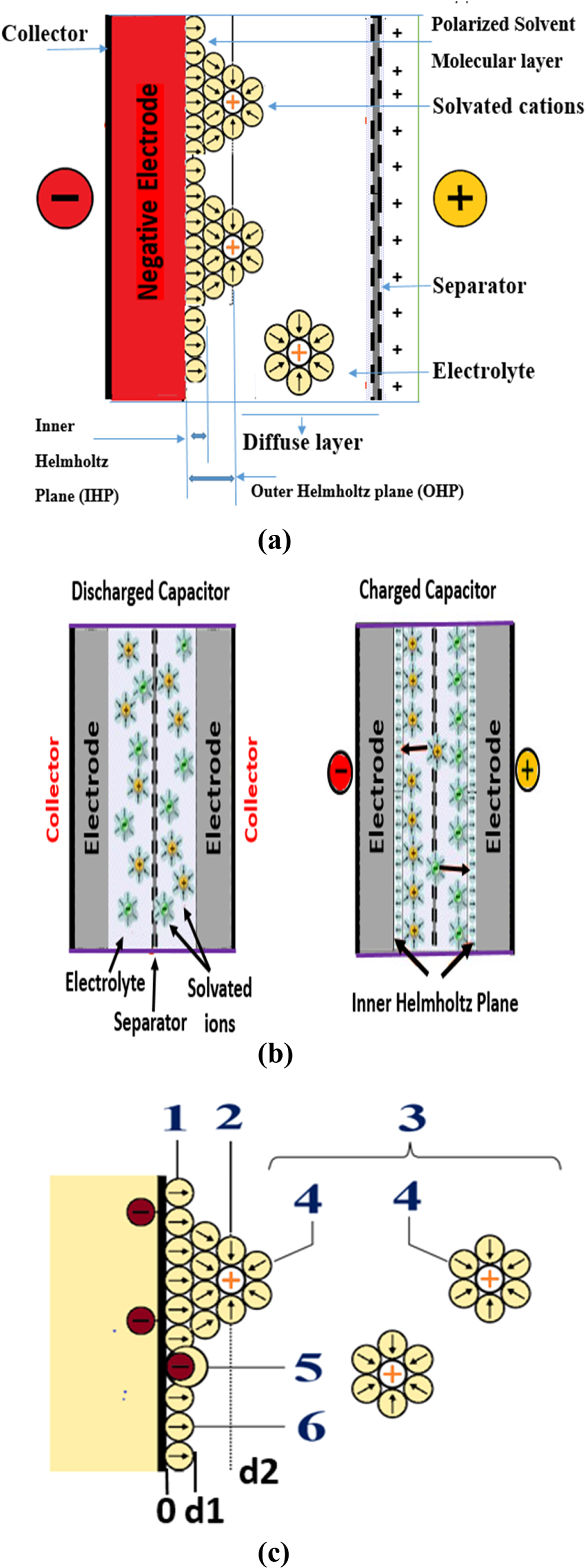
Whereas, the process of storage of energy in EDLCs relies on the formation of the electric double layer formed at the interface of the electrolyte and electrode of the system. EDLCs are identified by remarkable number of cycle life and great value for power density, making them suitable for fast energy storage and instant energy release. EDLC differs from an aluminium electrolytic capacitor. EDLC does not uses any conventional dielectric. EDLC uses an electrolyte (liquid or solid) lying in the middle of the electrodes in place of a dielectric (figure 1(a)). An electric double layer (EDL) is thus formed between the electrolyte and electrodes of the EDLC. This EDL behaves like the dielectric. The capacitance produced in the case of EDLC is therefore, directly dependent on the specific surface area (SSA) of the EDL formed between the electrolyte/electrode interfaces. So, in order to attain higher values for the capacitance, materials having large surface area (like activated carbon, CNTs etc) are used for making electrodes.

Figure 1. (a) Representation of Supercapacitor with double layer (b) Supercapacitors discharging and charging state (c) Representation of an electric double layer. 1. Inner Helmholtz plane, (IHP) 2. Outer Helmholtz plane (OHP) 3. Diffuse layer 4. Solvated ions 5. Specifically Adsorbed ions (redox ion, which contributes to the pseudocapacitance) 6. Molecules of the electrolyte solvent.
Download figure:
Standard image High-resolution imageThe cycle life of EDLC depends upon the ion absorption and desorption to the EDL formed at the electrolyte and electrode interface. EDLC is charged by inducing potential to the electrodes. The ions are attracted towards the surface of the EDL while charging and move away while discharging (figure 1(b)).
Pseudocapacitors on the other hand are different than EDLCs and exhibit pseudocapacitance. Pseudocapacitance depends upon the faradaic reactions that take place on the electrode surfaces. Specific electrode materials that can contribute to pseudocapacitance are used for their fabrication. Materials used as electrodes in pseudocapacitors are metal oxides, like MnO2, RuO2 and Co3O4 and conducting polymers. These materials are used as they can undergo the required redox reactions. The whole process involves potential induced adsorption on charged electrodes, redox reactions, and intercalation processes. The capacitance thus obtained is termed as pseudocapacitance. In comparison to EDLCs, pseudocapacitors exhibit higher capacitance and energy density but relatively lower power density. Faradaic processes being relatively slower than non-faradaic ones decrease the power density. Moreover, as redox reactions take place at the electrode, pseudocapacitors often lacks cycling stability.
The third type of supercapacitors i.e. hybrid or asymmetric supercapacitors are gaining attention in recent times. They have shown improvement in energy density while retaining good power density. Their specific capacitance is observed to be higher than the existing pseudocapacitors and EDLC. These hybrid or asymmetric supercapacitors mark a new beginning towards the environment friendly yet proficient energy-storing devices. Asymmetric supercapacitors have the advantage of having two different electrode materials. This extends the range of their operating voltage beyond the thermodynamic decomposition voltage of electrolytes while enabling a solution to the energy storage limitations of symmetric supercapacitors [19]. It is widely accepted that hybrid supercapacitor has two electrodes having charge-storage mechanisms different from each other: one battery-type Faradaic and one capacitor type. On the other hand, asymmetric supercapacitors have a wider range of electrodes. Their electrode materials can contain a hybrid device (if the active materials exhibit different charge storage mechanisms or have a varying ratio of redox-active sites on the electrode material) or they can have different redox-active electrolytes. Even a supercapacitor with the same EDLC carbon material but having different surface functional groups is considered as asymmetric supercapacitor [19]. So, one can say that hybrid devices are one of the various types of asymmetric devices.
2. Proposed theories
In order to understand the generation of electrochemical capacitance in supercapacitors, understanding both EDL capacitance and pseudocapacitance is utmost important. Knowledge regarding EDL capacitance and pseudocapacitance makes it easier to understand hybrid or asymmetric capacitors which in layman language are the combination of EDL and pseudocapacitative materials. Moreover, even in pseudocapacitors, presence of EDL capacitance is there but the value of pseudocapacitance is much more than the value of the double layer capacitance. So, one can say that pseudocapacitance is part of electrochemical capacitance, which exists together with an EDL capacitance. Both capacitances combine to give rise to a supercapacitor. As a result one can say that in order to understand the electrochemical capacitance of a supercapacitor, one has to understand the theory behind EDLC. Many theories have been proposed to understand the process involved in generation of electric double layer capacitance. The theories proposed are modified with time to incorporate the pseudocapacitive materials.
In an electric double layer supercapacitor, energy is saved between an electrolyte/ionic liquid and a conducting (semiconductor or metallic) electrode interface by the reversible adsorption of ions on the surface of the electrode possessing high surface area with varied porous structure. The counter ions thus accumulated on the surface of the charged electrode constructively resemble the second half of a parallel-plane capacitor of width d equated to the ionic radius = a/2 ('a' being the diameter of the ions). Taking the mean-field approach and assuming the ionic charge to form a charged plane, one can arrive at the expression for capacitance C as given by equation (1).

Where, ε is the electrolyte's dielectric constant
ε0 is the permittivity of vacuum
A is the electrode's surface area and d = a/2
The expression was first predicted by Helmholtz in 1853 and is known as Helmholtz capacitance. For studies under mean-field approximation of the Electric Double Layer, C/A provides the value for maximum capacitance per unit area.
The basic construction of EDLC device is close to the basic construction of batteries. The electrodes are constructed by coating active materials (carbon based) on the surface of the current collectors. Then, a membrane containing pores made up of glass fibre, paper or polymer is kept between the electrodes. Finally, the whole system thus formed is submerged in an electrolyte. Electric double layer EDL results from strong interactions between the electrolytic ions/molecules and the surface of the electrodes. Due to deficiency or excess of charged particles, a thin layer of charge appears on the surface of the electrode (at the electrolyte/electrode interface). On the other hand, in the area surrounding the electrode surface, surplus of either anion or cations results in an opposite charge in the electrolyte. Thus the EDL is made up of the whole array of oriented dipoles and charged species present at the interface of electrolyte/electrode. Unlike a standard electrolytic capacitor, the capacitance of EDL is generally potential dependent.
Several models and theories are researched upon to explain the observed behaviour of electrode in electrolyte under potentiostatic control. Following are the examples of such models.
2.1. Helmholtz theory
In order to understand the EDL, Helmholtz provided the theoretical foundation. Under the influence of applied voltage to the supercapacitor (EDLC), two layers of polarized ions are formed at the electrolyte/electrode interfaces (figure 1(a)). One layer is present at the surface of the crystal grains of the electrode which are in contact with the electrolyte. The second layer having opposite polarity opposite to the first one is formed from solvated and dissolved electrolytic ions that have been attracted towards the polarized electrode. A monolayer of solvent molecules separates the two layers of opposite polarity formed. This molecular monolayer is called the inner Helmholtz plane (IHP). It works as a molecular dielectric separating the oppositely polarized ions. The quantity of charge present on the electrode is balanced by the opposite-ions present in the area known as the outer Helmholtz plane. This area known as outer Helmholtz plane or OHP lies near to the inner Helmholtz plane, where the polarized ions of the electrolyte are received. Depending upon to the strength of the voltage applied, the charge on the EDL forms a stable electric field in the molecular layer of inner Helmholtz plane of the solvent molecules. The amount of electric charge accumulated in the layers depends upon the electrodes surface area and the number of the ions adsorbed. In order to find the EDL capacitance, the model assumes a charge density independent, constant differential capacitance Cd. It depends upon the charge layer separation δ and dielectric constant ε and can be calculated using equation (2).

For water as the electrolyte solvent, permittivity of value 6 is generated under the influence of the high potential. The value for the separation of the layer δ is 0.3 nm. Using these values, the predicted value of Cd, using Helmholtz model, comes out to be around 18 μFcm−2 [20]. If the surface of the electrode is known then the value obtained for the differential capacitance may be utilized to find the values of the capacitance using the equation (1) used for capacitors. As per equation (1), the capacitance C is inversely proportional to width between the plates (d). It is directly dependent on the surface area (A) and permittivity. Therefore C is greatest for components made up of substances with a high permittivity ε value, electrodes made up of materials with large A and a small d. Due to high surface area, activated carbon is used as electrodes. This results in the formation of an exceptionally thin EDL with value of d in the range of few angstroms.
A supercapacitor is made up of two electrodes. Therefore, at one electrode, the Helmholtz layer's charge is opposite in polarity to that of the other electrode's Helmholtz layer. So, the value of the total capacitance of an EDLC is the resultant of series combination of two capacitors. In the case of symmetrical SC, the capacitance value is almost same for the two electrodes. In such a case, the total capacitance is thus approximately half that of the value of the capacitance of either electrode. The Helmholtz model was the first theory to provide an approximate explanation for the arrangement between the ionic layer and electrode in a supercapacitor. However, the theory was insufficient as it was not able to explain the interactions that occur further away from the electrode in the electrolyte and the rise of pseudocapacitance.
2.2. Gouy chapman model and gouy chapman stern theory
Helmholtz gave the initial models to understand the behaviour of EDL, it was L G Gouy (1910) and D L Chapman (1913) who noticed that in an EDL, the capacitance does not have a constant value. They find the capacitance to be varying with the ionic concentration of the electrolyte as well as with the potential applied. They gave a diffuse model for the EDL. Gouy Chapman model thus made significant improvements in the prevailing knowledge of that time about the EDL. Their model described the ionic charge distribution to be dependent on their distance from the electrode surface. This assumption allowed the application of the Maxwell Boltzmann statistics. Thus the electric potential was found to be decreasing exponentially as one moves far from the surface of the bulk fluid.
In spite of the earlier success, there were certain unanswered observations in the real EDL and the model thus had limited quantitative applications. It was found that the model fails to give exact explanation for highly charged electric double layers. To rectify the discrepancies, Otto Stern (1924), proposed to combine the Helmholtz model and the Gouy Chapman model to explain the EDL. In Stern's model, two layers were suggested. The inner one called the internal stern layer was present due to the firm sticking of few ions to the electrode as initially proposed by Helmholtz. The other layer of ions was given the name 'Gouy Chapman diffuse layer' [21].
The Stern layer considered the impact of the finite size of the ions and thus suggested that the value of the closest ionic approach to the electrode should be approximately equal to the radius of the ion.
The Stern model also has its limitations. The model treats the ions effectively as point charges. It presumes that all the noteworthy inter activities taking place in the Gouy Chapman layer are coulombic in nature. The model also assumes that the fluid viscosity lies in a constant plane and the dielectric permittivity remains constant throughout the EDL.
2.3. Grahame theory
D C Grahame in 1947 provided a modification to the Stern model [22]. He proposed that although, mostly the solvated molecules remain close to the electrode but some charged or electrically neutral particles can go through the Stern layer. It could happen if ions, while approaching the electrode, lose their solvation shell. 'Specifically adsorbed ions' was the name given to ions which are in direct contact with the electrode and these specifically adsorbed ions were later found to be the reason behind pseudocapacitance. Depending upon the presence of specifically and non-specifically adsorbed ions, Grahame further divided the Helmholtz region in two planes. The inner Helmholtz plane (IHP) and the outer Helmholtz plane (OHP). IHP crosses through the centres of the specifically adsorbed ions. OHP lies at the distance of closest approach of non-specifically adsorbed ions (solvated ions) to the electrode, passing through their centres. The region beyond outer Helmholtz plane constitute the diffuse layer.
The SC in practice can be specified by several layers (figure 1(c)). The inner layer which is closest to the electrode is known by several names like Helmholtz layer, compact layer or Stern layer. This layer consists of the molecules of the solvent and sometimes the ions or molecules which are specifically adsorbed. This inner layer is divided into 2 planes: IHP and OHP. The IHP passes through the electrical centres of the ions which are specifically adsorbed, while the OHP lies in the plane representing the closest distance between the electrode and the solvated ions. OHP is also known as the starting point of the diffuse layer. The diffuse layer consists of solvated ions which are non-specifically adsorbed.
Due to thermal agitation of the electrolyte, the ions adsorbed non-specifically are circulated from the OHP into the bulk of the solution and thus form a 3D diffuse layer. The solution's total ionic concentration is used to find out the thickness of the diffuse layer. In EDL, the total charge density of the solution is made up by the contribution of the total charge density from ions, specifically adsorbed, and are present in the inner layer plus the total excess charge density present in the 3D diffuse layer. Hence, the capacitance of the double layer can be obtained by taking the capacitance due to the diffuse region of EDL Cdiff and Helmholtz type compact double layer capacitance CH in series combination. Therefore, the total capacitance of the EDL can be calculated through equation (3).

For a perfect EDLC, the charge is completely shifted to the EDL. No faradaic reactions takes place between the electrolyte and the solid material. So, the capacitance dQ∕dV is independent of the voltage and thus is a constant [12].
In pseudo capacitors interaction between the electrolyte and solid material involves faradaic reactions. The 5th point of figure 1(c) represents the contribution to pseudo capacitance. Hence the charge transferred becomes voltage dependent making the pseudo capacitance (dQ∕dV) voltage dependent as well. Pseudo capacitors involve three types of electrochemical process. Redox reaction involving ions present in the electrolyte, Surface absorption of ions present in the electrolyte, and electrode doping. To estimate the characteristics of the device, average capacitance is calculated by using the formula given by equation (4).

Where Qtot is the total charge, Vtot is the change in voltage during charging or discharging of the electrode. The average capacitance as calculated above can then be used in calculating the specific capacitance (Cavg−1). The value of specific capacitance of substances used in pseudo capacitors is much higher than that of carbon, the widely used electrode material for EDLC.
All the theories mentioned above are the original works that laid the principles of the double layer behaviour. These theories proposed the fundamental equations governing the phenomenon of electric double layer formation in SC. However, these ideas are the basic guidelines for development of models for supercapacitors but they by themselves are not enough to model supercapacitor devices as there are other phenomenon like porosity and thickness of electrode, properties of electrolyte etc. which have to be taken care of to predict the actual behaviour of the a supercapacitor cell. Following section gives the actual models used to describe SC by various researchers.
3. Theoretical studies
3.1. Theoretical models
Supercapacitors cannot be used or studied as normal capacitors because of the complex dependence of their terminal voltage on the previous use. The terminal voltage changes considerably after fast charge-discharge cycles. Thus, a simple resistive capacitive RC circuit proved to be insufficient to describe the behaviour of supercapacitor. Based on physical reasoning, many modified RC circuits are proposed to model a supercapacitor system but none of them is able to take into account all the parameters of SCs and can study the impact of interfacial electric field and temperature variation simultaneously. This is the reason of the difference between the theoretical and practical results of a supercapacitor system. To have a more accurate model, capacitance dependence of polarisable electrodes on potential, mechanism of self-discharge and variation of temperature should be taken care of. The value of conductivity of electrolyte in electrode's pores, pore resistance, ballistic transport as well as the conductivity of the electrode should also be studied. SCs shows two type of capacitance:
- (i)
- (ii)

Where
F: Faraday constant
n: mean number of electrons transferred in redox reaction
M: metal oxide's molar mass
V: operative voltage window
These capacitance values are used for the calculation of power density and energy density of supercapacitor cells. Supercapacitors energy density is given by equation (6) and power density is given by equation (7).

With maximum power density:

Here, R is the equivalent series resistance of all the elements used in the SC. Verbrugge and Liub [28] gave the micro structural models that can investigate the effect of thickness of the electrode and internal area, the porosity and size of the particle, electrode and electrolyte's material significantly. Another major aspect of SCs that should be accounted for is self-heating which if left uncontrolled can lead to the process of thermal runaway. The rapid increase in experimental studies on SCs demand the development of modern theories for SCs that can aid the experiments. Therefore, those SCs can meet the modern day requirements and become commercially viable [29]. Theoretical models started with the mean-field continuum model and Helmholtz model. Then came the models based on the surface curvature. Finally the modern day atomistic simulations arrived. Ideal models of supercapacitors are achievable with the help of molecular dynamics and the help of advanced computing softwares. In comparison to the amount of theoretical and computational work done on EDLCs, theoretical modelling of pseudocapacitors is limited [30]. Due to the complexity of interfacial redox processes, it is difficult to devise an exact method for modeling pseudocapacitors. Several factors like the diffusing EDLC, behavior of reactants and surface redox kinetics have an impact of pseudocapacitance. These issues are difficult to be covered in a single model. In the absence of any appropriate model, developing one to investigate the pseudocapacitance is urgently required. However, some theoretical studies have been done using classical equations (such as PNP and PB equations) to describe the solid/liquid interface and atomistic modeling based on quantum mechanics, density functional theory DFT and molecular dynamics. Following are the proposed models for studying SCs:
3.1.1. Empirical modelling
Zubieta and Bonert proposed the starting empirical models that focussed on the rate of change of capacitance, consisting of 3 RC branches [31]. The first or immediate branch consisted of a combination of a capacitor with fixed value of capacitance and a capacitor whose capacitance was dependent upon the voltage. This immediate branch was used to show the voltage dependence of the capacitance of a supercapacitor. Simulated and experimental results were in good agreement for operating voltages greater than 1V when subjected to same charge cycles. The error between theoretical and experimental values increased for voltages less than 1V or 45% of the rated voltage 2.3V. This was due to the assumption that only the immediate branch capacitance was made voltage dependent. Basically empirical models are based on empirical electrical equivalent circuit having three branches. The immediate branch capacitance depends upon the voltage whereas the long term branch is representing charge variation only. Empirical models are better than simple RC circuit (a simple electrical circuit made up of resistance and capacitance only) in describing the electrical characteristics of SCs. Another study was done by Diab et al to model the double layer capacitor using two RC branches [32]. The immediate branch to study energy evolution during charge-discharge cycles and the delayed branch. Different equivalent circuits were suggested to study the leakage current, self-discharge and diffusion controlled self-discharge. These models can be easily used for simulations. The electrochemical decomposition and parallel leakage process (independent of voltage) has been studied using simple models to explain the charge-discharge behaviour of the SC. Using these models, the limiting voltage window can also be predicted. These models are useful but have some limitations as well. If there is a significant rise in temperature of the SC system, then they are not capable of taking it into account thus can give inaccurate results for such cases. For the operating condition different from those used for parameter extraction, empirical modelling is not as accurate as required.
3.1.2. Dissipation transmission line models
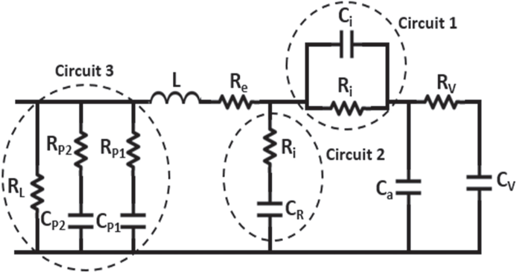
Electrode's porous nature is the main reason for the non-linear rise of terminal voltage. First order is sufficient to study the region of the bulk electrolyte, therefore one must have a model to describe the response of the porous electrode region. De Levie developed the first model based on porous electrode. Rafik et al [33] developed a simple equivalent electrical circuit (figure 2) to find how SCs depend upon the voltage (V), frequency and temperature (T) by combining Zubieta voltage model and De Levie frequency model.
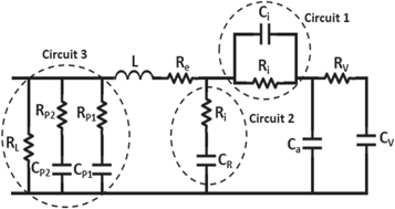
Figure 2 . Equivalent electrical circuit. Reprinted from [33] Copyright (2007), with permission from Elsevier.
Download figure:
Standard image High-resolution imageIn order to incorporate the supercapacitors dependence on temperature in the low frequency range, additional circuit was used having a parallel combination of temperature dependent electrolyte ionic resistance RT and capacitance Ci. At high frequencies Ci cancelled out the contribution of RT. the temperature dependence of RT was given by equation (8)

Where,
R20 is the value of RT at 20 °C,
T is the temperature and
KT = 0.025 °C−1
In the low frequency range, the total differential capacitance was given by the sum of Ca, CR, CP1, CP2, and 2KVV, where KV is the linear coefficient. For temperature below 0 °C, CP1 shows the dependence on the temperature and voltage given by equation (9).

It was found that temperature had negligible effect on capacitance Ci whose value remains of the order of 260 F for frequencies lower than 15 Hz. The model gave results in agreement to the experimental results. Dissipative transmission line model is advantageous because it provides a direct link between time response and pore structures and gives a measure of the exponential decay/rise in the level of the voltage. These models are built on the physical structure of the electrolyte/electrode interface therefore are particularly used only for processes like electrode synthesis improvement [34], guessing the electrode's surface impedance [35] etc. Even though transmission-line models have many advantages, one of their main drawbacks is that they are difficult to scale when series or parallel combination of number of SC cells are involved. Therefore, when a real SC system needs to be analysed, analytical models, which are addressed in the following section, are usually preferred.
3.1.3. Continuum models:
To study the electrolyte and electrode interface, continuum models generally use the Poisson-Nernst-Planck (PNP) notion of electro diffusion. The modelling does not use constant value for the physical and chemical parameters but uses them as the functions of their surroundings because of the high interfacial electric field. For simulations based on ordered mesoporous electrode structures, a continuum theory based 3D model was developed by L Pilon and Harnan Wang [36]. The morphology of the electrode made up of CP204-S15 carbon having mesopores, manufactured by Woo et al [37] was simulated by Hainan Wang and Pilon model and the model also accurately accounted for the finite size of the ion and the diffuse layer, stern layer etc. The areal and gravimetric capacitances Cs and Cg were estimated using equations (10) and (11).

Where: Q: charge
Φs: potential at the electrode electrolyte interface
As: area of the stern/diffuse layer interface

Where V and ρ are the volume and density of the electrode made up of amorphous carbon, respectively.
The values of Cs and Cg for ions which are non-solvated and have diameter a = 0.68 nm comes out to be 10.2 μFcm−2 and 97.9 Fg−1 respectively against the experimental value of 9.4μFcm−2 and 95 Fg−1. So, the theoretical values were 8.5% and 3% greater than their respective experimental values. However for solvated ion diameter a = 1.40 nm, Cs and Cg came out to be 7.5μFcm−2 and 72 Fg−1 respectively which were about 24% lesser than their observed experimental values.
1D continuum transport model are also used to describe the hybrid pseudocapacitor based on the lithium intercalation and diffusion in metal oxide [38]. The objective was to design rules for pseudocapacitive electrodes ensuring that the hybrid pseudocapacitor operates exclusively in the faradaic regime. Continuum model was used to capture the combined effects of diffusion coefficient for intercalation, electrode thickness and scan rate.
Similar study was done to develop a model to describe a RuO2 based pseudocapacitor. The focus was to study the variation in pseudocapacitance along the thickness of the electrode [39]. It was found that thick electrode resulted in losses especially at the end of the oxidation phase. A high ion concentration was assumed in the electrolyte. In another study, a one-dimensional model to investigate the performance of a battery/electrochemical capacitor-hybrid system was developed [40]. Simulation results were presented for LiCoO2∣LiPF6 ethylene carbonate/dimethyl carbonate ∣ carbon battery system and a Maxwell PC 10F carbon double-layer electrochemical capacitor. Many identical series/parallel capacitors were included in the model by introducing the parameter, capacitor configuration index. A substantial improvement in the energy density was observed while operating hybrid systems under high power densities [40].
3.1.4. Atomistic models
Some of these models use classical and quantum Molecular Dynamics (MD) and rest are based on Monte Carlo. The ionic subsystem of the electrolyte can satisfactorily be described by classical models like [41, 42]. But such models do not give any knowledge about the electrode's electron subsystem. Another research was carried out on Carbon having nano pores to study the interfacial restraining effects of aqueous sodium chloride on it [43]. The study was done using molecular dynamics. Although the entire study was done in the absence of applied voltage, it suggested that cylindrical pore size greater than 2nm are well suited for such system. Molecular dynamics simulations have also been done to see the effect of rough wall Nano channels on the electro-osmotic flows [44] and it was found that electrostatic potential decreases with an increase amplitude and decrease period of surface roughness.
Another good replacement of conventional electrolytes are Ionic liquids (ILs). However sufficient research has not been done on EDL formation in ionic liquid. The Gouy-Chapman theory is not sustainable for ILs due to their property of having large concentration of ions. The theory to explain The EDL in ILs was therefore proposed. It was developed using the lattice gas model, and in order to find EDL's diffused capacitance, the analytical equation (12) was given [45].

Where C0 is the linear Gouy-Chapman capacitance
u0 is the dimensionless potential at electrode's boundary
γ is the ratio of the total number of bulk ions and the total available sites
With γ tending to zero, the equation (12) gave the Gouy-Chapman law
Since the model did not take into consideration intra molecular charge distribution, the asymmetry of molecules and ion's specific adsorption at the surface, therefore another study was conducted [46] using ionic liquid 1-butyl-3-methylimididazolium-hexafluoro-phosphate [BMIM][PF6] at the surface of graphite using the help of MD. It was shown that the double layer's integral capacitance depends upon the polarity of the electrode. The values that were calculated for the capacitance of double layer matched with the order of magnitude with the values of specific capacitance measured experimentally at the electrode/electrolyte interface of activated carbon (electrode) and imidazolium based ionic liquids (electrolyte).
Molecular dynamics has also been used to study the relationship between change in temperature and the capacitance. Theoretical and experimental work in case of RTIL electrolytes showed a positive relation between the two [47, 48], a negative relation was shown in some studies [49] and even a bell shaped dependence in some studies. Therefore an in depth investigation is further required to understand the relationship between temperature and capacitance of a supercapacitor. Molecular modelling do not concentrate much on ionic transport and kinetics involved in charging-discharging of dense RTIL electrolytes in nano porous carbons, which can be helpful for obtaining optimum values of power and energy densities.
The computational requirements and accuracy of these models depends on the type of electrolyte and electrodes to be modelled. For example, in order to reduce simulation cost, a simple model can be chosen, which considers electrodes as walls and ions as hard spheres. However, such unrealistic assumptions reduce the accuracy and the ability to compute electrostatic properties.
3.1.5. Quantum models
Ab initio quantum chemistry and density functional theory DFT are the major parts of quantum models. The Car-Pirandello approach [50] allows the study of electrode's electron-hole subsystem and electrolyte's ionic sub-system in a one calculation. Lankin et al [51] also conducted such model using density functional theory DFT, which not only described the system of the electrolyte and solid electrode but also the EDL at electrolyte/electrode interface. The first stage calculations were performed using classical molecular dynamics. The quantum molecular dynamics calculation was performed in the later stage to describe the correct distribution of charges under the applied potential. The specific capacity thus obtained for graphite as electrode in a double layer system with 10M KOH solution as electrolyte was 3 μFcm−2 which was much smaller than the observed capacity (20–70 μF cm−2) of the double layer involving metal as electrode and aqueous solutions of salts and alkalis as electrolyte. It was concluded that the electric double layer in the electron-hole plasma of graphite has much stronger effect on the capacity of the system as compared to that of double layer in the electrolyte.
Many studies based on DFT have been done for electrode materials used in pseudocapacitor and hybrid capacitors [52–56]. Joint density functional theory (JDFT) was used to simulate the pseudocapacitive behaviour of RuO2 (110) [57].Capacitive curve obtained was comparable to the experimental cyclic voltammetry (CV) curve showing a redox peak position. Electronic chemical potential and total energy were calculated by JDFT in the JDFTx package with the implementation of linear polarizable continuum model (linear PCM). Ultrasoft pseudopotential was used to describe the nuclei-electron interaction. The total capacitance was defined by the total charge per unit chemical potential shift: Qtot/Δμ. Pseudocapacitance values calculated were in agreement with the experimental CV curve. For negative potential, very high capacitance over 200 μFcm−2 was obtained.
Another study on RuO2 based pseudocapacitive electrodes under realistic conditions was carried out to understand the microscopic factors that affects the pseudocapacitance [58]. Electronic-structure methods were used with a self-consistent continuum solvation (SCCS) model to build a complete data set of free energies [58]. Simulations reveal that minute changes (∼5 μFcm−2) in the double-layer capacitance can vary pseudocapacitance by large values (∼ 40 μFcm−2) [58].
Lately, density functional theory DFT is used to calculate quantum capacitance QC of graphene [59–63] and MXene [64, 65] based electrode for SC applications. Quantum capacitance of electrodes is calculated using the density of states DOS computed using DFT. If ϕ is the operating voltage and Q is the surface charge on the electrode then from density of states DOS(E), we can find quantum capacitance using equations (13), (14) and (15):


Where, e is the electronic charge
 is the Fermi-Dirac distribution function and E is the energy w.r.t the Fermi energy.
By definition, one can obtain quantum capacitance by differentiating Q w.r.t ϕ i.e.

Studying quantum capacitance is important as the specific capacitance of an electrode in supercapacitor is a resultant of two capacitances namely EDLC capacitance CEDL and Quantum capacitance QC as represented by equation (16).

It is clear from the above equation that a low value of quantum capacitance can significantly decrease the total electrode capacitance. Therefore, apart from looking for advanced electrolytes, finding electrode materials with a high QC is a good way to increase the capacitance.
Classical density functional theory CDFT is widely used to study electric double layer structures in aqueous electrolyte but not for the case of non-aqueous electrolyte. Simulations based on CDFT have good agreement with experimental investigations proving the relevance of CDFT in the ionic system. The complete process of energy storage in EDLC can be studied using CDFT. However, it cannot help to investigate the impact of the ionic charges, size of the solvent molecules, shape of electrode etc on the SC based on organic electrolytes.
3.1.6. Simplified analytical models
These models use mathematical equations to describe the flow of charged particles as well as the reaction rate [66–69]. These models use partial differential equations to characterize SC's electrical behaviour. Another model for asymmetric super capacitors was developed by Kazaryan et al [70]. This model helps in calculating the energy capacity, energy efficiency of charge-discharge cycles, electrode's specific capacitance and electrolyte's conductivity. It was found that for voltage range 0.8–2.2 V, the experimental and theoretical values of the above mentioned quantities for heterogeneous electrochemical supercapacitors of PbO2∣H2SO4∣C system are in agreement. However above 2.2 V, there is a slight divergence between the two. They also showed that SC's specific energy increases with the increase in the specific capacitance of the polarisable electrode and energy efficiency of the charging- discharging cycles varies with the thickness of the electrode, conductivity and value of charge/discharge current. The analytical models do not consider the electrolyte showing non-homogeneity in the vicinity of the interface and thermal coupling variables. Therefore they cannot predict the aging process of SCs.
When a model is designed for a complex system like supercapacitor, one has to search a suitable software or program which can be utilized for the development of that particular model. Different programs have different impact on the model's development process and thus have different advantages and disadvantages. Important programs available for carrying out supercapacitor related simulations are discussed below.
3.2. Simulation software/programs
Though a lot of studies have been done and researches are going on the supercapacitors but still SC is a rather new component as far as its commercial usage is considered. Whenever a new system like supercapacitor is designed, it becomes vital to create a model of that system using computer simulations to check the feasibility of the system. In order to study the supercapacitor system theoretically, researchers have tried to create models [71]. Complex models resembling the actual SCs have also been designed [72]. Graphical interface is used in most of the model building process, where wires are used to connect different components of supercapacitors. Most of the programs use electrical components for model creation, with wires having the ability to carry electrical and ordinary signals both. The only exception to this is Simulink where modelling is done using mathematical components and only signal values are carried by the wires. The various software packages available for SC modelling are discussed in the following sections:
3.2.1. SIMULINK
Simulink, a part of MATLAB is a software package created to make the analysis and modelling of dynamic systems easier. This is considered to be a standard for conducting simulations. Many programs can share the platform with Simulink to run co-simulation. Some can only export or import from Simulink through specific interfaces. The possibility of integration of Simulink makes this program widely used. Simulink models use the script language of MATLAB for advance calculations. Simulink mostly has mathematical and signal handling blocks. However the building blocks can be measured by adding new tool boxes like simpower systems, sim drive lines and sim hydraulics etc. For known system equations that can be stated by state space equations then Simulink's signal flow modelling is advantageous. This modelling can be applied from different domains to such systems. Although mathematical modelling is the property that separates it from other programs focused at electrical modelling but it has its disadvantage as well. For studying different types of input, entirely different models have to be created which adds to modelling time. Parameter estimation tool can also be added to Simulink. Several outputs are given different weights so that weights for the important output can be set higher to achieve better accuracy. Plots like cost function, parameter sensitivity etc. are predefined for analyzing the results. V V Busher et al modelled supercapacitors as shown in figure 3 using fractionally integrated circuit in Simulink [73]. The standard deviation of the calculated voltage with respect to that obtained experimentally comes out to be 0.0049V (0.38%) during charging and 0.0035V (0.27%) during discharging, indicating the validity of the proposed circuit.

Figure 3. Supercapacitor model. Reproduced with permission from [73] https://eltecs.opu.ua/index.php/journal/article/view/833.
Download figure:
Standard image High-resolution imageIn the field of electricity generation, hybrid wind power system consisting of wind generation systems, fuel cells and ultra-capacitor is attracting a lot of attention. Such a system was modelled using Simulink/MATLAB platform [74]. The equivalent circuit consisting of capacitance C, equivalent resistance in series ESR and equivalent resistance in parallel EPR was used for the modelling of the supercapacitor as given in figure 4.

Figure 4. Equivalent circuit. Reproduced with permission from [74] Copyright (2006), with permission from Elsevier.
Download figure:
Standard image High-resolution imageThe series and parallel arrangement of ultracapacitors in the practical ultracapacitor system determines the terminal voltage and the total capacitance can be given by equation (17).

Such ultracapacitor system is capable of satisfying the external load demand during peak requirement. The following figure (5(a)–(c)) represents the results obtained.
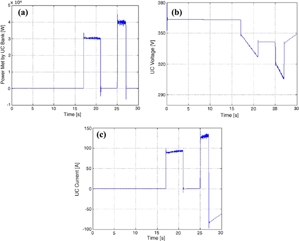
Figure 5. (a): Power satisfied by SC [74] (b): Variation of Voltage with Time [74] (c): SC change in current with demand in power. Reproduced with permission from [74] Copyright (2006), with permission from Elsevier.
Download figure:
Standard image High-resolution image3.2.2. SIM POWER systems
Sim power systems not only contains standard circuit elements like capacitors, transistors but also more advanced components like electric drives, FACTS, PWM generator etc. Basically it is a toolbox that can be added to Simulink for modelling electrical circuits. The problem of causality does not exist, which is a major advantage in Sim Power Systems.
In comparison to Simulink, here the input can be changed without altering the modelled circuit. This reduces the simulation time. One has to be very careful while connecting capacitors or inductors as a voltage source connected in parallel to a capacitor or current source in series with inductor can create major errors during simulations. Not only continuous simulation of power system can be done, but one can use discretization and phasor simulations as well in Sim Power Systems.
3.2.3. OrCAD capture
Generally capture and PSpice are run in the OrCAD program suite where circuit designing is done in OrCAD capture. Mainly electrical circuit designing and simulations are done using this program. PSpice program is used for simulation calculations and result presentations. AC/DC sweep, bias point and transient simulations are possible. Stress analysis, Sensitivity analysis and Monte Carlo analysis is also possible with OrCAD EE designer PLUS, an extended version of OrCAD capture. Calculation method used by PSpice is node analysis. Equation system is generalised in matrix form for all nodes. Combination of gauss method and Newton Raphson method is used [75]. In an experimental study [76], carbon nanotube (CNT) supercapacitor was designed using poly (ethylene terephthalate) substrate from a printable multi-wall CNT ink as electrodes and aqueous NaCl as electrolyte. The impact on capacitance by Galvanostatic measurement current was investigated through Galvanostatic discharge measurement. The effect was further investigated by using an RC model for supercapacitor as shown in the figure 6(a). Simulations were carried out using Cadence OrCAD capture software.

Figure 6. (a): Circuit used for simulation at charging voltage of 0.9V, Ci = 11mF, Ri = 100Ω and Load resistance 130kΩ [76] (b): Comparison of Capacitance obtained from simulation and measurements at Different values of current. Reprinted by permission from Springer Nature Customer Service Centre GmbH: [76] (CopyRights 2014).
Download figure:
Standard image High-resolution imageThe values of the circuit components were chosen to fit the experimental results and the capacitances were obtained with the help of the simulated discharge curves as shown in figure 6(b). Corresponding to leakage current obtained at 0.9 V, 130 kΩ leakage resistance was obtained for the model.
3.2.4. PSCAD
EMTDC (Electromagnetic Transients including DC) solution engine is used to do calculations whereas PSCAD only provides a graphical layer to draw circuits and to present the results. MATLAB can be used in a PSCAD model with the help of a subroutine created using FORTRAN language. Special Blocks like slider control are included in the component library to do model alteration during simulations. This helps to directly view the results. There are no restrictions on how the circuit elements can be combined, which is a major advantage over some other software. During simulations, a snapshot can be taken and that snapshot can be used as starting point for further testing [77]. Supercapacitors find their applications in various fields. They can be used in supercapacitor energy storage system (SCES), used to control the voltage fluctuations in a whole wind farm. The effectiveness of such a control system involving supercapacitors was validated by using PSCAD software [78]. It was found through simulation that supercapacitor can be charged to 1.1 kV reference voltage and discharged at 0.18 kV and thus can maintain the wind farm terminal voltage at 1 pu.
3.2.5. SABER
SABER, a program created by company synopsis enables full-system virtual prototyping for applications in analog/power electronics and in generation, conversion and distribution of electric power. It verifies the behaviour of thermal, electrical, mechanical like physical systems having multi domain. Design analysis like stress, Monte Carlo etc. can also be implemented. Time taken for computing intensive statistical analysis is minimized with the use of grid computing. Its modelling tools include model creation, characterization and conversion. It also includes MAST modelling. This can be used for smart grid optimization for the power management of supercapacitors.
3.2.6. PLECS
For system-level simulations of electrical circuits, Plexim has developed this software tool PLECS. PLECS has an approach running down from top. It makes the modelling and simulation of entire systems, including loads and power sources easier. It has a comprehensive library of components covering the electrical, thermal, magnetic and mechanical features of the systems under consideration and their controls. Typical components like semiconductor, inductors etc. are simply connected by drawing wires. Dr John Schonberger did the modelling of a simplified as well as frequency dependent supercapacitor using PLECS [79]. He used lumped parameter circuit (as shown in figure 7) to model the two types of supercapacitors.

Figure 7. Supercapacitor model. Reproduced with permission from [79] https://plexim.com/files/plecs_supercap.pdf.
Download figure:
Standard image High-resolution imageThe model was utilized to investigate the thermal aspect of the given system as well. For frequency dependent case, at low frequencies, the small signal capacitance was found to be 3000F. The simulation results were in good agreement to an experimental study done by F Rafik et al [80].
3.2.7. DYMOLA
Based on the open Modelica language, DYMOLA provides modelling and simulation environment. The dynamic behaviour of the system is described with the help of mathematical equations. Models in DYMOLA can have components from multiple domains. It generates efficient simulation code by processing the complete system of equations. It supports the hiding and encryption of information. Import and export of data is done according to Functional Mock up interface (FMI). Several simulation platforms can use the exported functional Mock up units without the requirement of any run time licence.
Table 1 gives the advantages and disadvantages of the software packages discussed above.
Table 1. The details of advantages and disadvantages of software packages used for Supercapacitors.
| Software | Advantages | Disadvantages |
|---|---|---|
| Simulink |
|
|
|
| |
|
| |
| Sim Power System |
|
|
|
| |
|
| |
| OrCAD Capture |
|
|
|
| |
| ||
| PSCAD |
|
|
| ||
| ||
| Saber |
|
|
|
| |
| ||
| PLECS |
|
|
| ||
| Dymola |
|
|
|
| |
|
4. Experimental advancements
For most of the practical applications, an ultra-capacitor is not characterized by the capacitance observed per unit area. It is best characterized by its volumetric capacitance i.e. capacitance per unit volume or capacitance per unit mass. This resulted in emphasis being given majorly on developing high valued SSA conducting materials to be used for fabricating electrodes for the Supercapacitor cell. In search of such materials, the more promising candidates are various varieties of carbon. Since they have very high values for SSA, Graphene, Highly porous carbons and carbon nanotubes are the most widely sort out substances that can be utilized to make electrodes in EDLC. The specific surface area in such devices, where they are used as electrodes, can be as high as of the value 1000 m2g−1.Various studies focussed on using different types of electrolyte have also been done. In order to construct a completely solid SC, a solid ion-conductor electrolyte has been tried, similar to batteries that can be recharged. Having a solid electrolyte in SC has many advantages. The most important being the elimination of the risk of electrolyte leakage. This can address various problems associated with the system's safety and reliability. Since supercapacitor systems involving liquid electrolytes are far simpler, so, mostly devices reported so far are based on liquid electrolytes. The most common liquid electrolytes used in EDLCs are aqueous H2SO4 or KOH. They have higher value for dielectric constant and electrical conductivity. Organic electrolytes are also been investigated. Few of them being propylene carbonate (PC) or tetraethylammonium tetrafluoroborate (TEA-BF4) in acetonitrile (AN). The use of such organic electrolytes can help in achieving higher voltage of the cell going up to 2.3 V, which is much higher in comparison to 1V obtained in case of aqueous electrolytes. In order to overcome the depletion problems associated with such electrolytes such that electrode's large surface area can be utilized completely, high concentrations of organic and aqueous electrolytes are used. Using higher concentrations also helps to increase the conductivity. Ionic liquid (ILs) used as electrolytes are also another type of electrolytes experimented upon. Their use as electrolyte can enable electric double layer capacitors to work even at voltages which have values higher than 3 V. Still, ionic liquids available at present ILs have drawbacks as well. In comparison to aqueous and organic electrolytes, they have higher viscosities and lower conductivities.
One of the major focus while designing a supercapacitor cell is its ability to store charge. The capacity to store charge in a SC depends on how easily the pores present on the electrodes surface can access the ions available. Therefore, the size of the pore and that of the ion should be optimal. The selection of the optimal size of the electrode surface pores is dependent upon the ionic size present in the electrolyte. This forces researchers to choose both electrode and electrolyte together.
4.1. Electric double layer capacitors
EDLC is a combination of electrodes, which are separated by a separator and electrolyte. Powder of AC is put on the surface of the electrodes. The EDL is formed on the plane where electrolyte forms a contact with the powder. The equivalent structure can be represented as shown in the figure 8.

Figure 8. Equivalent circuit for SC.
Download figure:
Standard image High-resolution image
In the figure 8, EDLC is depicted by cathode capacitor Cc and anode capacitor Ca, electrode resistance (consisting of electrode and collector) (R1 and R2), inter electrode resistance (consisting of resistance of the separator and electrolyte) (Rse), and insulation resistance (Ri1 and Ri2).
The whole mechanism of charging and discharging is given in great detail in Reference [81]. EDLC have extremely high breakdown field strength as compared to that for conventional capacitors. The large SSA of electrodes and small separation between the charges in the double layer give rise to high values for specific capacitance. Rightmire was the first one to describe EDLC [82]. With increase in their energy density, longer charge-discharge cycles, researchers saw them as a replacement for batteries. They behave better with temperature fluctuations. Electrodes fabricated using reduced graphene oxides rGO, activated carbon AC and carbon nano tubes CNTs are widely used to increase the specific capacitance and the energy density of EDLCs. Long CNTs has been grown on a conducting substrate and the measurement indicating towards the electrical properties of the electrodes if applied to EDLCs have been provided. [83]. The group has shown that the energy densities up to 21 WhKg−1 are achievable for 2.7 V voltage using the electrodes made up of VCNT having value for the specific capacitance of the order of 225 Fg−1. It is predicted that for 2.7 M electrolytes, increase in working voltage 3.5 V will result in energy densities approximately 7 times higher than that available with commercial activated carbon EDLCs but these nano-structures are costly and need to have highly sophisticated synthesis and fabrication technology to achieve high capacitance values in order to reduce cost of energy storage, activated carbon are still most promising electrode materials. Most commercial SCs use activated carbon AC as electrode material because it has high specific surface area, relatively low costs [84] and excellent electrochemical properties. But the irregular pores of AC give rise to low accessibility to electrolyte ions in case of organic non-aqueous electrolytes. Either the pores are narrow or closed for the passage of electrolyte ions. To overcome the problem, carbon substances having mesopores are also utilized to make electrode [85–87]. Carbon having controlled size and volume of the pores were synthesized using mesostructured silicates as a hard template substance [88]. Such mesoporous carbon materials exhibited better electrochemical performance in comparison to AC but the degree of improvement in Cm is less because the surface area of mesoporous carbon is relatively low.
Many studies have observed that micro pores can also contribute to Cm significantly [89–92]. Thus, it can be said that structures having macropores, mesopores and micropores have better electrochemical performance in comparison to single sized pores material. The macropores facilitate the bulk transfer of electrolyte but no charge storage takes place in such type of pores, while mesopores provide intermediate channels to electrolyte ions and able them to form double layer and pass on to micropores (whose ions form compact double layers).
Non suitable size of the pore of the electrode material hinders the passage of ions present in the electrolyte. For resolving this problem associated with the size of the pore of the electrode material of SC, hierarchically structured activated carbon HAC was designed. A carbon/mesoporous silica template composite was synthesized and was chemically activated to increase the volume of the pores and for simultaneous removal of the silica template [93]. The hierarchically structured activated carbon thus prepared has a well-made structure of the electrode pore and thus allowed large number of electrolyte/electrode interfaces for the efficient EDL formation resulting in higher specific capacitance (157 Fg−1) and high rate capability.A three dimensional 3D hierarchical Nano cages based on Carbon having simultaneous presence of micro-meso-macropores, large SSA and fine conductivity was reported using in situ MgO template method [94]. They demonstrated high super capacitive performance. Another porous Cu template method is developed to make nano materials based on 3D hierarchical porous carbon [95]. A unique 3D, carbon resembling few layer graphene, 3DG was made. It had large SSA (greater than 1500 m2g−1), interconnected micro-meso-macropores, high wet ability and high conductivity in both ILs and aqueous electrolytes. Electric double layer capacitors that are based on the 3DG and are prepared at 1000 °C delivered ultra-high maximum power densities of 740.8 KWKg−1 and 1066.2 KWKg−1 in IL and aqueous electrolytes respectively. Recently, three-dimensional (3D) graphene frameworks (3DGF)-based hybrids have been considered as electrode material for supercapacitor. A study reported that incorporation of functional nanomaterials into 3DGF, to obtain 3DGF-based hybrids may exhibit better properties in comparison to 3DGF [96]. The study indicated that 3DGF-MCS with 10 wt% MCS have excellent electrochemical performance with a superior specific capacitance of value 288.77 Fg−1 [96]. The study suggested that 3DGF-MCS may be considered as electrode materials for supercapacitor.
The carbon synthesis procedure and the source from which carbon is obtained affect the electrochemical performances of carbon significantly. Carbon is obtained by pyrolysis from pitch, polymers and coal. Carbon derived from coal can have impurities like Al2O3, Fe2O3, CaO etc [97–101]. Carbon derived from polyvinyl chloride PVC has the limitations of having very low specific surface area because of the absence of optimal pores [102]. Porous carbon obtained from biomass has also attracted a lot of interest of the researchers. Carbon derived from biomass like dead plant leaves [103], paper pulp mill's bio waste [104], swim bladders [105] and chicken eggshell membranes [106] have been studied. As against carbon obtained from conventional sources, biomass sources are abundant in nature. Such sources are renewable, clean and therefore sustainable. They can provide carbon at comparatively lower costs. Biomass materials are rich in Oxygen, Phosphorus, Nitrogen, and Sulphur. These elements, after pyrolysis, can convert carbon to self-doped heteroatoms. Such hetero atoms can enhance the electrical conductivity of carbon by contributing to the pseudo capacitance of the system [107–110]. Highly porous carbons from sorghums vinasse (concomitant with the liquor industry) are also obtained using simple methods [111]. The carbon obtained has quite a high value for Specific Surface Area = 3047 m2g−1and unique graphene nano platelet micro structure that provides high values for electrical conductivity and capacitive activity [111]. Use of pine needles as encouraging precursor substance for the production of micro porous N-doped carbon frameworks as high performance HER catalysts on large scale and for super capacitor electrode has also been reported [112]. The laser treatment of activated carbon electrodes also abbreviated as LSAC leads to the formation of micro channels that can connect the internal pores of activated carbons with the electrolytes surrounding the electrode thus enabling better activity in between the surface of the electrode and ions of the electrolyte.
When the above mentioned types of electrodes are combined with an aqueous ferrocyanide/ ferricyanide redox electrolytes, create super capacitors with high energy density, higher capacitance and larger potential window [113]. This energy between LSAC and redox electrolyte produce SC with 8 times larger capacitance than traditional super capacitors made up of nonscribed activated carbon electrodes with an acetonitrile-based electrolyte.
For EDLCs, electrodes having high values for power density and high values for volumetric energy density are desired. An effective approach to optimize the porous structure and thus to increase the energy density by collapsing the carbon nano cages via capillarity is reported [114]. 3 Samples with reducing size of meso and macro pores demonstrated the interrelations between the volumetric performance of the EDLC and the porous structure. It was indicated that reducing the excess macro and mesopores increases the specific energy density, while maintaining high values for the power density.
Flexible supercapacitors FSCs based energy devices are also attracting attention these days. They find their applications in electronic equipment like displays, mobile phones etc, which can be bent or folded [115–118]. Graphene sheets have singular structure that make them appropriate for gathering thin films with excellent flexibility and good conductivity [119]. In order to use graphene significantly, it is required to minimize the re-stacking of its sheets [120, 121]. Free standing flexible hybrid papers were constructed by combining graphene sheets and porous carbon powder [122]. These hybrid papers have large SSA, large packing density, good electrical conductivity and outstanding flexibility. Volumetric electrochemical performance was found to be better than electrodes constructed from carbon particles brought together with a binder. Two electrode Swagelok type cells were used for making the electrochemical evaluations using 1M H2SO4 as electrolyte. An outstanding areal capacitance 103 mFcm−2 at very high current densities going up to 1400 mAcm−2 and areal energy density 12 mWhcm−2 at high power densities of 316 mVcm−2 were reported. Electrospun carbon nanofibers (ECNFs) due to their flexibility are also considered as the electrode material for FSCs. However, the poor electrical conductivity of ECNFs limits their practical applications. In order to improve the properties, porous carbon polyhedra embedded carbon nanofibers were doped by N and S and (NSCPCNF) was synthesized [123]. The resultant NSCPCNF had enhanced specific surface area, improved charge transfer ability and pseudocapacitive contribution by N, S dopants. FSC assembled by NSCPCNF electrodes achieved a high specific capacitance of 103 Fg −1 at 0.5 Ag−1 (two-electrode mode) and high energy density of 14.3 Whkg−1 at the power density of 250 Wkg−1, which is better than most of the reported ECNFs based FSCs [123]. The assembled FSC also exhibited superior bending stability. Study suggested that NSCPCF can be considered as electrode material for high-performance FSCs.
These type of EDLC supercapacitors are being experimented and are trying to find the place in the market. But these advancements could not replace the 'organic electrolyte based activated carbon EDLCs' which is commercially available but for very limited applications, because of their low capacitance values resulting in low energy density values. In the series of advancements in the potential material applications to supercapacitors; these materials were categorized in transition metal oxides and conducting polymers, related discussion will appear in next section.
4.2. Pseudocapacitors
Pseudocapacitors store electrical energy through the redox reactions taking place between electrolyte and electrode. The whole process involves potential induced adsorption on charged electrodes, redox reactions, and intercalation processes. The capacitance thus obtained is termed as pseudocapacitance.
Pseudocapacitors are generally been investigated by using metal oxide [124, 125] or conducting polymer material [126–128] as their electrode. Ruthenium oxide is widely used for pseudo capacitors [129] because of its higher specific capacitance than carbon and conducting polymers but it is very expensive and toxic. Due to good capacitive performance Manganese, oxide is also emerging as a material for pseudo capacitor electrodes [130]. It is relatively cheap and environment friendly. In comparison to RuO2, MnO2 has lesser conductivity. However to address this problem its composite form with CNTs are used [131]. The composite exhibits excellent energy storage capacity. A nanoscopic uniform layer made up of MnO2 was formed over the surface of the MWCNT while retaining its indigenous structure during the coating process. The value of specific capacitance of this composite electrode as given by the cyclic voltammetry curves comes out to be 250.5 Fg−1. It is notably higher than the value obtained for a pure MWCNT electrode.
Conducting polymers that are used for the purpose of electrode include polypyrrole, polyaniline (PANI) and poly-(3, 4-ethylenedioxythiophene) (PEDOT) have values of specific capacitance as good as of metal oxides [132, 133]. Even the composite electrodes are investigated to see the effect on capacitance. One such study [133] was done using electrodes made up of Poly (3, 4-ethylenedioxythiophene) and polypyrrole PPycomposite. The specific capacitance of these composite electrodes is much greater than the values obtained for electrodes fabricated using either pure PPy or PEDOT. This increase may be attributed to the collaborative effect of PPy and Poly (3, 4-ethylenedioxythiophene) (PEDOT).Moreover, for the composites prepared on the surface of PPy with horn-like structure, the specific capacitance reaches up to a value more than 200 Fg−1 and have satisfactory charge-discharge cycle. The study indicates that PEDOT/PPy composites can be used for fabricating electrode material of supercapacitors.Although conducting polymers have huge SSA and can be doped to have metallic conductivity but they do not have sufficient mechanical stability during charge- discharge cycles [134]. These pseudo capacitors deliver high capacitance with high energy density, but low voltage of electrode limits their specific power density. Metal oxides and the conducting polymers are operative upto 1 V, which limits power delivery. Contrary to this, EDLCs deliver huge power density with large cycle life. To combine these two goods of different devices, the concept of hybrid supercapacitors is evolved by scientists. These hybrid SCs are further modified with battery type electrodes.
4.3. Hybrid or asymmetric supercapacitors
Regardless of the huge research in the area of supercapacitors, EDLCs and pseudocapacitors are still way behind the required energy density demands. Graphene has been observed to be the most suitable substance for fabricating electrodes of the supercapacitors [135] due to high values of its SSA (upto 2630 m2g−1) and electrical conductivity (106 Scm−1). But due to the restricted values of capacitance of electrodes fabricated using graphene, to bridge the gap of demand and supply and to incorporate the advantages of EDLC and pseudocapacitors, researchers are focusing on hybrid or asymmetric supercapacitors (SC). Hybrid or mixed supercapacitors use electrodes with different characteristics. Generally one electrode shows the property of electrostatic capacitance while the other exhibits pseudocapacitance. Another variety of hybrid supercapacitors are fabricated by using electrodes made up of composite of pseudocapacitive material and electrostatic capacitive material. Many studies have shown that the composite electrodes synthesised using glucose assisted hydrothermal method have improved capacitance as compared to the electrodes of graphene or pseudocapacitive material only [136].
The capacitive performance of SC having cathode as Ni3S2/3D-Graphene (G) and anode as Fe3O4/rGO composite has been studied [137]. For characterization, XRD measurements and energy dispersive x-ray spectroscopy (EDS) were done. Specific capacitance (Cm) value of Fe3O4/rGO electrode comes out to be 447, 461, 412 and 303 Fg−1 at 5, 10, 20 and 50 mVs−1 respectively, which is larger in value than that of pure Fe3O4 or pure rGO electrode. Major contribution to specific capacitance comes from the pseudocapacitance of nanoparticles of Fe3O4 rather than from reduced graphene oxide(rGO).The composite prevents the formation of groups of nano particles and allows fast transport of electron through the basal rGO layers to Fe3O4 nanoparticles [138, 139]. The values for Cm of the device NiOOH/Ni3S2/3D-G//Fe3O4/rGO were found out at 5, 10, 20 and 50 mVs−1. The values for specific capacitance were found to be 233, 214, 192 and 167 Fg−1 respectively [137]. The energy density (E) and Power density (P) of the ASC were obtained by equations (18) and (19).


Where ΔV is cell's operating voltage and
Δt is the discharge time.
At power density of 930 WKg−1, the device can provide high value for energy density equal to 82.5 WhKg−1.Another study done on nanoparticles of RuO2 (Hydrous Ruthenium Oxide) tied up to carbon nanotube (CNT) and graphene hybrid (RGM) used as electrodes of supercapacitors has shown better values for gravimetric capacitance (502.78 Fg−1), power density (128.01 KWKg−1) and energy density (39.28 WhKg−1) [140]. The research group lead by Lin, Jian integrated three dimensional GM architecture [141] and hydrous nanoparticles of RuO2 synthesised through sol-gel by dip coating process. The process provides a graphene layer foam covered with hybrid networks of anchored CNTs and nanoparticles of RuO2. The hybrid RGM provides a hierarchical and porous structure. It enables the active material (CNT-RuO2 layer) to access sufficient electrolyte, shows increase in conductivity and improvement in transport of the charge. Their RGM system provides a technique for preparing high energy electrodes without requiring a binder.
Flexible hybrid supercapacitor is realized by using electrodes made up of nano sheets of graphene and ultra-thin 2D MnO2 [142]. This flexible supercapacitor had remarkable performance electrochemically. It was the first time when ultra-thin nano sheets of 2D MnO2 (MSs) were created using soft template method achieving a high value for Cm (774Fg−1) even after 10000 cycles. Asymmetric supercapacitors fabricated using electrodes made up of graphene and MSs gives remarkable energy density E (97.2WhKg−1).
Another suitable candidate for having a better performance of the CNT-based supercapacitors is Polypyrrole (PPy). Good environmental stability, less cost and high capacitance adds to the advantages of using PPy. Highly flexible all-solid-state supercapacitor fabricated using composite films and fibres of CNT/polypyrrole has been studied [143]. The values for Cm of the solid composite of CNT/Ppy goes up to 139.2 Fg−1(10mVs−1) and 331.4 Fg−1(5 mVs−1) in a solid fibre SC when the CNT/Ppy composite film is directly twisted into a fibre.
In another study, Ni3S4/CuS2 nanocomposite having a Rubik's cube like structure was fabricated by vulcanization of Ni(OH)2/CuS2 [144]. Specific capacity of 888 Fg−1 at 1 Ag−1 current density was obtained for the nanocomposite in aqueous solution of 2M KOH. Asymmetric electrodes assembled using Ni3S4/CuS2//RGO have shown a high energy density of 49.68 Whkg−1 with power density of 400Wkg−1 [144]. Another material which is attracting interest for fabrication of SC electrodes is Metal-organic framework (MOF). In a study, Ni/Co-MOF was fabricated by a facile hydrothermal method [145]. The Ni/Co-MOF had a dandelion-like hollow structure and exhibited an excellent specific capacitance of 758 Fg−1 at 1 Ag−1 [145]. Ni/Co-MOF and active carbon were then used in assembling asymmetric supercapacitor. The SC exhibited a high specific energy density of 20.9 Whkg−1 with power density 800 Wkg−1 [145]. Such results demonstrate that the electrochemical property of the MOFs can be improved when mixed-metals are used for their fabrication.
In the field of flexible energy devices supercapacitors lag behind because of poor flexibility and especially low energy density. One way to improve the energy density of SC is by expanding the voltage window. This can be done by using the hydrogel electrolyte. A study reported a zwitterionic natural polymer hydrogel with excellent mechanical strength and flexibility as electrolyte for assembling a solid-state zinc-ion hybrid supercapacitor (H-ZHS) with Zn foil and AC electrode [146]. A wide and stable voltage window of 2.4 V was obtained with maximum energy density of 286.6 Whkg−1 at the power density of 220 Wkg−1 and superior capacity retention of 95.4% after 2000 cycles [146]. The strategy presented in the work provided a new insight in exploring H-ZHC for flexible wearable electronic devices. Table 2 summarizes some of the latest experimental advancements in the field of supercapacitors.
Table 2. Latest important experimental advancements in the field of supercapacitors.
| System | Reference | Specific energy (in Wh/kg) | Specific power (in W/kg) | Specific capacitance (F/g) | Operating voltage (V) |
|---|---|---|---|---|---|
| Asymmetric SC, Ni(OH)2/CNT/NF anode and AC cathode | [147] | 50.6 | 95 | 3300 | 1.8 |
| Activated graphene in acetonitrile. | [148] | 74 | 338–103 | 174 | ----- |
| Asymmetric SC, NiOOH/Ni3C2/3D Graphene and Fe3O4/Graphene electrode in 1M KOH | [149] | 82.5 | 930 | 233 | 1.6 |
| PPy/AC composite electrode | [150] | 56.4 | 30 | 45.1 | 3.0 |
| Hollow RGO/conducting polymer composite fibers(HCF) electrode in PVA/H3PO4 gel electrolyte | [151] | 27.1microWh/cm2 | 66.5microW/cm2 | 63.1 | ------ |
| Pure TiC-CDC(Titanium carbide-carbide derived carbon) in TEMABF4 in Acetonitrile (AN) | [152] | 20 | 200*103 | 112 | 3.4 |
| Highly porous carbon with a graphene nano platelet microstructure in 2M KOH | [153] | 49.5 | 10.8*103 | 329 | 3 |
| Co-Cd selenide (Cd-Co-Se)//Fe, Battery-supercapacitor hybrid (BSH) | [154] | 68 | 1200 | 892 | ------- |
| carbon-modified hexagonal boron nitride, h-BN/C nanocomposite in 2M KOH | [155] | 17 | 245 | 250 | 1.45 |
| hybrid supercapacitor with 3DGraphene/ NixCo1-xO composite as the cathode and 3DG as the anode | [156] | 27.2 | 725 | 697.8 | ------- |
| Positive electrode made up of MnO2/ hollow carbon nanofibers (HCNFs) nanocomposites and negative electrode made up of KOH-activated porous carbon nanofibers (PCNFs) | [157] | 35.1 | 497.3 | 63.9 | 2 |
| asymmetric supercapacitor based on the Ni/Co-MOF and reduced graphene oxide (RGO) | [158] | 42.24 | 800 | 568 | 1.6 |
5. Advancement in supercapacitor technology
Hybrid supercapacitors also known as asymmetric supercapacitors can be fabricated using several combinations of materials like NiO [159], RuO2 [160], Ni(OH)2 [161], Co3O4 [162], MnO2 [163] and V2O5 [164]. Among these, MnO2, due to its abundance and environmentally friendly nature has attracted the researchers to work on MnO2 based systems. Apart from being widely available and eco-friendly, it also has a large value of specific capacitance theoretically (1,380 Fg−1) [165]. The energy density of the hybrid supercapacitors using MnO2- LSG (laser scribed graphene) varies from 22 to 42 Whl−1 depending on the mass loading and configuration (asymmetric, symmetric or sandwich) of MnO2 [166]. Such high values implies that the supercapacitor systems using LSG– MnO2 can store approximately 6 times more than the commercially available electric double layer carbon supercapacitors. They are also superior to pseudocapacitors, sodium-ion battery hybrid and hybrid of supercapacitor–lithium-ion battery (Li-ion capacitors). Power density going up to 10 kWl−1 can be obtained by LSG-MnO2 hybrids. The value is almost 100 times higher than lead acid batteries and about 1,000 times higher than batteries made up of lithium thin-film. All these facts make hybrid supercapacitor a potential candidate for filling the void in the energy and power demand chart.
The past three decades have experienced a large scale of experimental and theoretical studies of the above mentioned types of supercapacitors. Substantial studies have been done in the area of using various types of carbon substances for EDLC like AC (activated carbons), carbide-derived carbons (CDCs), template carbons, carbon onions, carbon nanofibres, single-walled carbon nanotubes (SWCNTs), multiwalled carbon nanotubes (MWCNTs), graphene etc. [167–173]. Almost all studies aim at improving capacitance of the available supercapacitors and are focused on exploring the impact of physical quantities and to explore the underlying fundamental principles of energy storage. Table 3 provides the comparison of various commercially available energy storage devices [174–178].
Table 3. Comparative parameters of different types of capacitors [174–178].
| Parameters | Batteries | Electrolytic capacitors | Carbon EDLC | Pseudo-capacitors | Hybrid/ Asymmetric supercapacitors |
|---|---|---|---|---|---|
| Specific Capacitance (Fg−1) | N/A | N/A | 20–400 | 20–1530 | 21–160 |
| Specific Power (WKg−1) | <1000 | >10000 | 500–10000 | 35–35000 | 10000–54000 |
| Specific Energy (Whkg−1) | 20–150 | <0.1 | 1–10 | 1–250 | 1–25 |
| Operating Voltage (V) | Low | High | <3 | 0.5–3.65 | 0.5–3.5 |
| Working Temperature (°C) | −20 to 60 | −55 to 125 | −40 to 70 | −25 to 60 | −50 to 85 |
| Charge-Discharge Cycles | ∼1500 | >>10^6 | >10^6 | 1500–70000 | 500–23000 |
| Efficiency | 0.7–0.85 | ∼1.0 | 0.85–0.99 | 0.94 | 0.60–0.95 |
6. Conclusions/Summary
The development of new clean energy sources is utmost important in the search of a substitute to usage of environmental unfriendly energy resources like coal and petroleum. As a result, supercapacitors are gaining more and more attention. Although not commercialized for all purposes but they are specifically used in memory protection in electronic devices. Ultracapacitors are also used in elevators, cranes and within modes of transport like cars, buses, trains etc. Electrochemical supercapacitors stand unique as they can have longer cycle life and yield high power density in comparison to batteries. The past three decades have seen extensive experimental and theoretical advancements in the area of electrical supercapacitors. Variety of carbon substances have been studied for fabricating the electrodes of the supercapacitor system. ACs, carbide-derived carbons (CDCs), template carbon, carbon onions, single-walled (SWCNTs) and multi walled (MWCNTs) carbon nanotubes, graphene, carbon nano fibres etc. [167–173] has been studied in detail for EDLC applications. The prevailing researches are majorly focussed on two motivations aiming at the improvement in specific capacitance, energy and power density: to find out the effective and ineffective physical quantities and to thoroughly investigate the basic energy storage principles.
Thus, it can be said that carbon structures having a combination pores consisting of macropores, mesopores and micropores have shown excellent electrochemical performance. On the other hand, single sized pore's (template) material has also been studied.
For resolving the pore associated bottleneck problem of the electrode material of SC, variety of electrolytes have been utilized. Aqueous H2SO4 or KOH, Organic electrolytes, like proplylene carbonate (PC) or tetraethylammonium tetrafluoroborate (TEA-BF4) in acetonitrile (AN), Ionic liquid (IL) electrolytes have been reported in different combinations and their influence on EDLC are discussed.
Pseudocapacitors are generally been investigated by using metal oxide [124, 125] or conducting polymer material [126–128] as their electrode. Ruthenium oxide is widely used for pseudo capacitors [129] because of its higher specific capacitance than carbon and conducting polymers but it is very expensive. Due to good capacitive performance Manganese oxide is also emerging as a material for pseudo capacitor electrodes [130]. It is relatively cheap and environment friendly. In comparison to RuO2, MnO2 has lesser conductivity. However to address this problem its composite form with CNTs are used [131].
Polypyrrole, Poly-(3, 4-ethylenedioxythiophene) (PEDOT) and polyaniline (PANI) having specific capacitance similar to that of metal oxides [132, 133] are the examples of conducting polymers which are also a good candidate for pseudo capacitors. Conducting polymers have huge SSA and can be doped to have good conductivity but they have certain disadvantages like having insufficient mechanical stability during charging-discharging [134] as discussed in this article.
The different theoretical models namely empirical model, dissipation transmission line model, continuum model, atomistic model, quantum model, simplified analytical model etc. have been discussed in details with their role in capacitance value and performance of devices.
Researchers have used and explained their experimental data with these theoretical explanations in different ways, according to their material, structure, type of charge storage mechanism and electrolyte. Despite of much work on theoretical modelling, appropriate models to design pseudocapacitors and hybrid capacitors are still lacking.
Various computational tools (software packages) have been proposed by various workers. Simulink is one of the widely used software packages.
Experimentation required to study various samples representing SC is expensive. It is sometimes not turn out to be cost effective because the results obtained may not necessarily match the expected output. Therefore, the dependence over simulation software is increasing day by day. But there are no specific software packages or any guidelines that can be used to study SC specifically.
There is a huge requirement for a dedicated software for supercapacitor devices and materials for electrochemical studies, particularly, Carbon, porous Carbon, metal oxides, conducting polymers etc. The prescribed software are used for studying the physical properties of these materials.
Among Hybrid or Asymmetric supercapacitors, MnO 2 -based systems are of particular interest as MnO 2 is found in huge quantities and is environmentally friendly. It has high values for the specific capacitance (1,380 Fg−1) theoretically. Hybrid supercapacitors using LSG-MnO2 as electrodes can store about 6 times the capacity of EDLC carbon supercapacitors that are available commercially these days. They are also better in comparison to hybrid of lithium ion battery-supercapacitor and pseudocapacitors. Power density provided by supercapacitors using LSG–MnO2 can go as high as 10 kWl−1, a value, which is almost hundred times higher than lead acid batteries and thousand times higher than a battery consisting of a thin-film of lithium. So hybrid capacitor is also a potential candidate for filling the gap between the energy and power demand. The choice of supercapacitor depends on the application and availability.
Despite of the remarkable theoretical and experimental advances made in the field of supercapacitors lately, still there is a significant difference between the energy densities of EDLCs (<10 Whkg−1) and batteries (100 Whkg−1 approximately). However, research in the field of supercapacitors has a rather short past. There is a huge scope for further optimization if the capacitance performance from the present values. Supercapacitors can only have a stand a chance against the prevailing battery technology if they can further increase their energy density along with their high-power density.
Acknowledgments
Dr. Yogesh Kumar acknowledges the financial supports received from the SERB Department of Science and Technology (Government of India) File no. ECR/2016/001871. The author (Bharti) acknowledges principal, Shivaji College, University of Delhi, India for constant encouragement and support. Dr.Ashwani Kumar would like to thank Council of Scientific & Industrial Research (CSIR), India for financial support under SRA Pool Scientist scheme (award no: 9131-A).
Data availability statement
The data that support the findings of this study are available upon reasonable request from the authors.