
Abstract
Inspired by a recent experiment [Phys. Rev. Lett. 122 253201(2019)] that an unprecedented quantum interference was observed in the way of stimulated Raman adiabatic passage (STIRAP) due to the coexisting resonant- and detuned-STIRAPs, we comprehensively study this effect. Our results uncover the scheme robustness towards any external-field fluctuations coming from laser intensity noise and imperfect resonance condition, as well as the persistence of high-contrast interference pattern even when more nearby excited levels are involved. We verify that an auxiliary dynamical phase accumulated in hold time caused by the presence of the quasi-dark state in detuned-STIRAP can sensitively manipulate the visibility and frequency of the interference pattern, representing a new hallmark to measure the hyperfine energy accurately. The robust stability of the scheme comes from the intrinsic superiority embedded in the STIRAP mechanism that preserves the coherence of population transfer, which promises a remarkable performance of quantum interference in a practical implementation.
Export citation and abstract BibTeX RIS
1. Introduction
Quantum interference effect serving as one of the most intriguing features that can distinguish a quantum system from classical candidates, has facilitated versatile applications in diverse systems, covering the range from electron source,[1,2] single-atom-cavity system,[3] superconducting device[4–6] to solid-spin system.[7–9] For realizing quantum interference, all accessible routes on different platforms essentially require at least more than two possible paths for transferring the information, returning a representation of small forces or energies in precision measurement,[10–12] quantum entanglement,[13–15] or quantum sensing[16] at the microscopic level. In reality, a high-quality interference based on the quality of a quantum system is still very limited due to the imperfect stability of external magnetic or optical fields under real implementation, which can sensitively dephase the interference by artificial measurement or noise effect.[17] Although a large number of approaches for overcoming the instability or imperfect measurement have been proposed, e.g., quantum nondemolition measurement allows repeated detection of quantum states without destroying them;[18] quantum plasmonics experiments exhibit remarkable preservation of coherence,[19] a more precise atom interferometry is achieved by transferring the photon momentum to atoms while minimizing its uncertainty;[20] however it is still challenging for realizing extremely stable quantum interference in a well-defined isolated system.
Thanks to the contributions by Liu and coworkers, an unprecedented observation of quantum interference phenomenon induced by the stimulated Raman adiabatic passage (STIRAP) was achieved recently,[21] arising a new avenue to precise measurement utilizing an absolute adiabatic system.[22] The STIRAP technique, basically benefiting from a well coherence-preservation, has been widely used for a deterministic population transfer among ground states with high efficiency.[23] Unfortunately, only (two-photon) resonant-STIRAP (or R-STIRAP) is favored by previous studies owing to the existence of an absolute dark eigenstate which is totally isolated from the influences of other bright eigenstates.[24] In contrast, detuned-STIRAP (or D-STIRAP) enabled by other nearby energy levels is usually ignored[25,26] because of the coexisting R-STIRAP making its impact less important. The achievement of the STIRAP-induced quantum interference effect unexpectedly reveals the virtue of D-STIRAP even if the resonant transfer is active, which can provide an accurate measurement for the tiny energy difference between hyperfine ground states.
Inspired by their experimental facts,[21] in the present work, we theoretically re-study the intriguing feature of quantum interference induced by the coexisting resonant and detuned STIRAPs in a multi-level Λ system. Our results can uncover the importance of D-STIRAP by adding a controllable dynamical phase between two quantum paths. The observed interference frequency and high-visibility that quantitatively rely on the strength of two-photon detuning in D-STIRAP, can be used as a reliable measurement for the ground-state energy difference in a practical implementation. Furthermore, the interference pattern obtained can persist a stable output against significant stochastic fluctuations from external laser intensity noise as well as the imperfect energy splitting of ground states. These results mainly ascribe to the remarkable stability and coherence possessed by a usual STIRAP system.[27,28] An extensive study with multiple excited states nearby also strongly confirms the robustness of this STIRAP-induced quantum interference in a practical multi-level atomic system.
2. Theoretical formulation
2.1. Reduced model and eigenenergy
As represented in Fig. 1(a), the energy levels |g0〉, |er,d1 〉 and |gr,d〉 describe the initial ground state, two middle excited states and two ground hyperfine substates. The pump and Stokes lasers with Rabi frequencies Ωp(t) and Ωs(t) resonantly coupling states |g0〉 → |er〉 and states |er〉 → |gr〉, serve as the basis of a round-trip STIRAP transition. Typically speaking, such a five-level model contains two STIRAP paths, which are named as D-STIRAP and R-STIRAP, enabled by the round-trip optical pulses as displayed in Fig. 1(b). More concretely, R-STIRAP refers to the transition of |g0 〉 ⇄ |er 〉 ⇄ |gr〉 with both one (or two)-photon detuning vanishing. Whereas D-STIRAP carries out among states |g0〉 ⇄ |ed1 〉 ⇄ |gd〉, accompanied by the one (two)-photon detuning Δ1 (δ) with respect to |er〉 (|gr〉).[29] As for a practical one-photon detuning Δ1 which is usually orders of magnitude larger than the hyperfine energy difference δ caused by Zeeman splitting of an external magnetic field, we first safely ignore the detuned state |ed1 〉 and pay attention to a four-level configuration. For example, in 87Rb atoms the level spacing between |er〉 = |52 P3/2,F = 2〉 and |ed1 〉 = |52 P3/2,F = 3〉 is about Δ1 ≈ 267 MHz[30] while the Zeeman splitting δ between |gr〉 = |52 S1/2,F = 2,mF = 0〉 and |gd〉 = |52 S1/2,F = 2,mF = 1〉 is only scaling of a few kHz typically.[31] For a complete study, the impact of multi-excited states nearby will leave for discussion in Section 4.

Fig. 1. (a)–(b) A five-level Λ configuration and the atom-field interactions, carried out by a pair of round-trip STIRAP pulses composed by two pumps and two Stokes lasers. Relevant parameters are described in the text. (c) The proof-of-principle experiment for realizing a STIRAP atom interferometer based on quantum interfering of the population undergoing different STIRAP paths.
Download figure:
Standard imageIn the rotating-wave frame, the four-level scheme Hamiltonian reads (ℏ = 1)[32]

where  is the projection operator, and the two-photon detuning δ characterizes the energy difference between |gr〉 and |gd〉. For R-STIRAP with δ = 0, there exists a dark eigenstate with its energy Ed = 0. At the same time, the adjacent magnetic substate |gd〉 detuned by δ [≠ 0] to the resonant level |gr〉 permits the D-STIRAP, which supports a quasi-dark-state (not eigenstate) energy Eqd. Here the round-trip STIRAP pulses adopting a generalized form of[33]

are displayed in Fig. 1(b), where τ is the delayed time between two pulses Ωp(s) and the amplitude function A(t) is given by
Here T is the common pulse length, Ω0,p(s) are the peak amplitudes of pump (Stokes) lasers.
Population initialized on state |g0〉 individually undergoing R-STIRAP and D-STIRAP paths will interfere with each other. In this case, if we detect the final population on state |g0〉 after all pulses, an oscillation pattern occurs as a function of the product of the hold time Δ T and the two-photon detuning δ. Such an interfering effect can serve as a new way for realizing a STIRAP atom interferometer. To qualitatively understand its essence, we first separately study them in decomposed three-level models, as shown in the insets of Figs. 2(a) and 2(b). The separated three-level Λ models that contain states |g0〉, |er〉, |gr〉 for R-STIRAP and states |g0〉, |er〉, |gd〉 for D-STIRAP, can be described by the reduced three-level Hamiltonians


and by diagonalizing Eqs. (4) and (5), we analytically solve all eigenvalues, which are

with


Fig. 2. Schematic time-dependent eigenvalues for (a) R-STIRAP and (b) D-STIRAP, depending on two three-level Λ structures (see insets). Here the dark-state energy Ed and quasi-dark-state energy Eqd are individually highlighted by the grey shaded region, respectively.
Download figure:
Standard imageA qualitative representation of eigenvalues is comparably shown in Figs. 2(a)–2(b). It is clear that the dark energy Ed ≡ ε0 persists zero due to the presence of an absolute zero-energy dark eigenstate  in R-STIRAP. While as for D-STIRAP there does not exist such an eigenstate; however, we observe a quasi-dark state |Eqd〉 with its energy Eqd shifted by δ during the hold time in which Ωp = Ωs = 0. As displayed in Fig. 2(b), this quasi-dark energy Eqd is marked by a grey shaded curve which composes parts of eigenenergies
  and
and  due to the emergence of two avoided crossings between them. Once the system evolves along with the quasi-dark state |Eqd〉, it will get an extra phase ΔΦ due to this shifted energy δ in Eqd. Finally, it leads to the population interference with that evolves along the dark eigenstate after the round-trip STIRAP pulses.
The proof-of-principle STIRAP atom interferometer can also be indicated with the help of STIRAP interfering effect. As demonstrated in Fig. 1(c), starting from the initialized state |g0〉 that the forward STIRAP pulse (Stokes exceeds pump) acts as the first "beam splitter" (BS) that coherently splits into two STIRAP paths, giving rise to a superposition state between |gr〉 and |gd〉. However, before the arrival of the second inverse pulse pair, there exists a hold time Δ T enabling a free evolution along with the absolute dark or quasi-dark states, accordingly. Until reaching the second BS (pump exceeds Stokes), the population will converge at state |g0〉 again. If detecting the final population of |g0〉 it reveals a clear interference pattern that strongly depends on the relative phase ΔΦ accumulated between the two paths. This behavior is analogous to the undergoing of different optical paths, which is the so-called STIRAP atom interferometer. By detecting the interference fringe, we can precisely obtain a relative phase ΔΦ and other information.
2.2. Coherent population transfer along individual STIRAP paths
In order to know the real population dynamics in reduced models that could help us understand the observation of interference more clearly, we begin with a study of population transfer and eigenstate evolution in individual STIRAP paths. Numerical results for the realistic time-dependent population dynamics come from solving a master equation

where the subscript r(d) refers to R (or D)-STIRAP, and the density matrix  is of 3 × 3 type.
  representing the influence of spontaneous decay from state |er〉, takes forms of

with Γ the decay rate. Pg0 , Per , Pgr(d) are defined by the diagonal elements of the density matrix representing the state population. We show the real population dynamics in Fig. 3(a1) for R-STIRAP that reveals a well-expected transfer perfectly coinciding with the ideal dark-eigenstate |sd〉 evolution as shown in Fig. 3(a2). That fact confirms the coherent adiabatic population transfer in R-STIRAP.
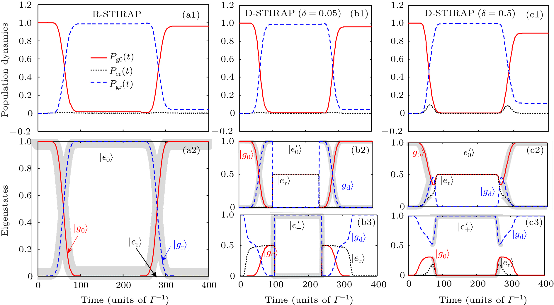
Fig. 3. (a1)–(a2) The real population dynamics and the evolution of zero-energy dark eigenstate |ε0〉 = |Ed〉 in R-STIRAP. (b1)–(b3) For the three-level D-STIRAP with δ = 0.05, the real population dynamics as well as the evolution of eigenstates  and
and  . Especially, the evolution of quasi-dark-state |Eqd〉 is highlighted by the grey shaded curves, which contains parts of
  and
and  . Similarly, (c1)–(c3) show the case of δ = 0.5. Here Δ T = 100, T = 100, τ = 20, Ω0 = 1 and Γ (Γ−1) treats as the frequency (time) unit throughout the paper.
Download figure:
Standard imageHowever, as for D-STIRAP there does not exist an absolute single eigenstate for achieving the adiabatic transfer since  ,
,  are all related to the lossy excited state |er〉. Because |er〉 suffers from an inevitable loss Γ that may break the adiabaticity of STIRAP. Fortunately, thanks to the emergence of avoided crossings by shift δ where the eigenenergies
  and
and  become degenerate. The expected population transfer labeled by the grey shaded curves as presented in Figs. 3(b2)–3(b3), first obeys |g0〉 of
  , and then jumps to |gd〉 of
  at the first avoided crossing. Subsequently, it returns back to |g0〉 of
  at the second avoided crossing. Benefiting from such a coherent population transfer between
  and
and  , Fig. 3(b1) shows a perfect population dynamics for D-STIRAP under δ = 0.05. Although the system does not contain a dark eigenstate, we find that the population dynamics agrees well with the evolution of quasi-dark state |Eqd〉, as shown by grey shaded curves in Figs. 3(b2)–3(b3). Therefore, our results indicate that the coherent population transfer can be well kept even in D-STIRAP as long as δ is suitable. Nevertheless, once δ is increased to 0.5 that is comparable to Ω0 [= 1.0] which may break the coherent transfer between
  and
and  at the avoided crossing point, the final population Pg0
(∞) on state |g0〉 becomes lower, see Figs. 3(c1)–3(c3). This is made by a larger energy gap at the avoided crossing when δ is increased, which leads to the decoherence effect by the excited-state loss in the process. To avoid this effect, we will adopt Ω0 = 5.0 in the calculation.
at the avoided crossing point, the final population Pg0
(∞) on state |g0〉 becomes lower, see Figs. 3(c1)–3(c3). This is made by a larger energy gap at the avoided crossing when δ is increased, which leads to the decoherence effect by the excited-state loss in the process. To avoid this effect, we will adopt Ω0 = 5.0 in the calculation.
So far, we have clearly shown the real population transfer as well as the ideal eigenstate evolution. Our results verify that both R-STIRAP and D-STIRAP can enable a perfect coherent population transfer in its individual three-level configurations as long as δ is appropriate.
2.3. Measuring interference pattern
To obtain the STIRAP interference pattern under the influence of the relative phase ΔΦ, we resort to the full system and numerically solve the master equation[34]
with  a 4 × 4 density matrix referring to the basis of |g0〉,|er〉,|gr〉,|gd〉, and the Lindblad operator
  is given by{[35]}
Note that Γ is the spontaneous decay rate from the resonant excited state |er〉 determined by its lifetime, and the population on state |g0〉 defined by Pg0(t) = ρg0
g0
(t) serves as the main observable quantity in detection. For t → ∞ it means the final time. Here ρij
(t) (i,j ∈ (g0,er,gr,d) stands for the element of density matrix  , and ρjj
(t) means the |j〉 state population. As predicted by the experiment,[21] we numerically study the relationship between Pg0(∞) and Δ T, and confirm its strongly oscillating behavior.
, and ρjj
(t) means the |j〉 state population. As predicted by the experiment,[21] we numerically study the relationship between Pg0(∞) and Δ T, and confirm its strongly oscillating behavior.
Before quantitatively understanding this relationship, we first solve for an analytical expression of the relative phase ΔΦ, which is

with Φd and Φr the accumulated phases in each STIRAP path, given by[36,37]

Here the total evolution time before the measurement is t = 2(T + τ) + Δ T. Eqd(t) and Ed(t) in integrals stand for the quasi-dark state and dark eigenstate energies, respectively; see Fig. 2 and texts below. Note that no phase is accumulated in R-STIRAP due to Ed = 0. However, for D-STIRAP we could get a non-zero phase accumulation. By replacing Eqd(t), a more concrete expression for calculating Φd is
We can define  due to the symmetry of
  by round-trip pulses, which describes the phase accumulated during the atom-light interaction region. The second term
  comes from a steady shift δ of quasi-dark energy
  during the hold time Δ T region. Therefore for a given δ, the phase difference ΔΦ between two paths is only determined by δ × Δ T since φ(δ) is unvaried. By adjusting Δ T, we observe a high-contrast interfering pattern, as plotted in Fig. 4(a), where the peaks from constructive interference locate exactly at ΔΦ = 2nπ (n ∈ integers). Note that the constructive interference could be enabled by the least phase difference with n = 1, which is ΔΦ = 2π = δ × (1/f), resulting in the oscillating frequency f of the interference pattern, analytically expressed as

It is clear that f increases linearly with δ.

Fig. 4. (a) The population Pg0(∞) oscillates after a round-trip STIRAP, as a function of the hold time Δ T∈[100,1100] for δ = 0.05. A parallel axis on top denotes the accumulated dynamical phase ΔΦ accordingly. (b) The frequency of the interference oscillation with respect to δ is comparably presented, where numerical and analytical results are respectively labeled by solid curve and dots. Similar to (a), (c) also shows the interfering pattern yet with the variation of δ. Here Δ T = 100, Ω0 = Ω0,p(s) = 5.0.
Download figure:
Standard imageA numerical verification as presented in Fig. 4(b) also shows a robust linear tendency between f and δ. In Fig. 4(b), the analytical expression of Eq. (16) is plotted by a solid line, while numerical results (black dots) are obtained from the frequency spectrum analysis when transforming into the frequency domain by Fourier transform. For every δ, it is possible to get a steady interference oscillation pattern within a hold time Δ T, like in Fig. 4(a). That fact, on one hand, provides a reliable determination of the Zeeman splitting energy δ under an adjustable external magnetic field; on the other hand, it interactively returns a high-contrast quantum interference effect for further practical applications. This visual STIRAP interference pattern can also be observed when transferring to the frame with respect to δ since ΔΦ is also δ-dependent. By scanning the hyperfine energy δ, a high-contrast interfering pattern can also be observed as shown in Fig. 4(c). However, this pattern turns to be a quick amplitude-damping behavior with the increase of |δ| due to the breakup of coherence between R-STIRAP and D-STIRAP. So only around the two-photon resonance, the interference pattern is best.
Here the pattern contrast or so-called visibility during a finite hold time Δ T given by[38]

can serve as a key parameter for describing the interference quality.  stands for the maximal (minimal) population during the hold time. The amplitude damping observed in Fig. 4(c) is due to the competing effect between R-STIRAP and D-STIRAP. When |δ| is small and appropriate, the population can be transferred along both paths efficiently as displayed in Figs. 3(a1) and 3(b1), arising a high-contrast interfering pattern. However, if |δ| is far from resonance, only the R-STIRAP will play a dominant role rather than the inefficient D-STIRAP, which would deeply lower the interfering amplitude as well as its visibility. The limit case is the atomic population would transfer along single three-level R-STIRAP path and finally return back to state |g0〉 without showing a visible quantum interference pattern. A detailed discussion for coherent population transfer of individual R- and D-STIRAP has been presented in Subsection 2.2.
3. Stable quantum interference
As have been shown in Ref. [39], the use of stabilized lasers is important for continuous measurement feedback in matter-wave interferometry. Due to the high requirement of measurement accuracy, any shift of interference fringe may return back necessary information about, e.g., hyperfine splitting energy, additional optical phase, which quantitatively determines the measurement quality. It is obvious that the hyperfine energy δ can be directly determined by measuring the frequency variation of the interference signal.[40] And the phase shift accomplished via a wavelength-modulated optical beam can be detected by solving the sequential interference signals that are quadrature with each other.[41] However, the laser system in the experiment can hardly acquire absolute stability because of the intensity noise even with the use of laser-frequency stabilization technique, which possibly destroys stable interference output. This noise may lead to a stochastic fluctuation to the laser Rabi frequency, or arising an imperfect two-photon resonance that breaks the dark state. It is clearly shown that benefiting from the optimal coherent population transfer based on two individual STIRAP paths our scheme can manifest an unprecedented stabilization towards stochastic fluctuations coming from the intensity noise as well as from imperfect hyperfine energy splitting.
3.1. Fluctuation from laser intensity noise
To verify that, we add significant fluctuations to the peak intensity of laser pulses by adopting the expression of

with the perturbation term δΩp(s) adopted from a range of [–δΩ,δΩ] and δΩ is chosen to be the maximal modulation amplitude. For comparison, we numerically study two ways of adding this laser intensity noise: i.e., δΩp(s) is a time-dependent stochastic value within [–δΩ,δΩ]; or δΩp(s) is modified to be a regular sinusoidal function which is δΩps)(t) = δΩsinω t,[42] and the frequency ω is arbitrary. Here ω = π/5. In the calculation, the maximal modulation amplitudes are δΩ = 0.2Ω0 and 0.5Ω0 [43] in cases (b) and (c) for comparing the variation with stronger fluctuations.
In Fig. 5, case (a) [the first column] represents the original laser pulse profile (Fig. 5(a1)), the realistic population dynamics under different hold times (Figs. 5(a2)–5(a5)), and the expected interference pattern (Fig. 5(a6)) under the condition of no fluctuation. Due to the change of hold time that gives rise to different accumulated phases in D-STIRAP, the final population on state Pg0(∞)(red-solid in Figs. 5(a2)–5(a5)) reveals a Δ T-dependent character, agreeing with the oscillating behavior in Fig. 5(a6). Furthermore, even under strong stochastic fluctuations to Ωp(s)(t), see the second and fourth columns of Fig. 5, where δΩ = (0.2,0.5)Ω0, our results confirm that the population dynamics as well as the interference pattern do not change at all, which are the same as the findings in Figs. 5(a2)–5(a6) with no fluctuations. The reason for that remarkable preservation of high-quality interference (black-solid) as displayed in Figs. 5(b6) and 5(c6) should be understood by the phase accumulation during the hold time Δ T, which critically depends on the quasi-dark energy Eqd. If δΩs(p) = 0, the phase difference shows a precise relation with respect to the splitting δ. However, as δΩs(p) ≠ 0, it will lead to an extra perturbed phase. Thanks to a stochastic fluctuation that arises a complete compensation of the phase change on average, the system could sustain the usual unperturbed phase difference.
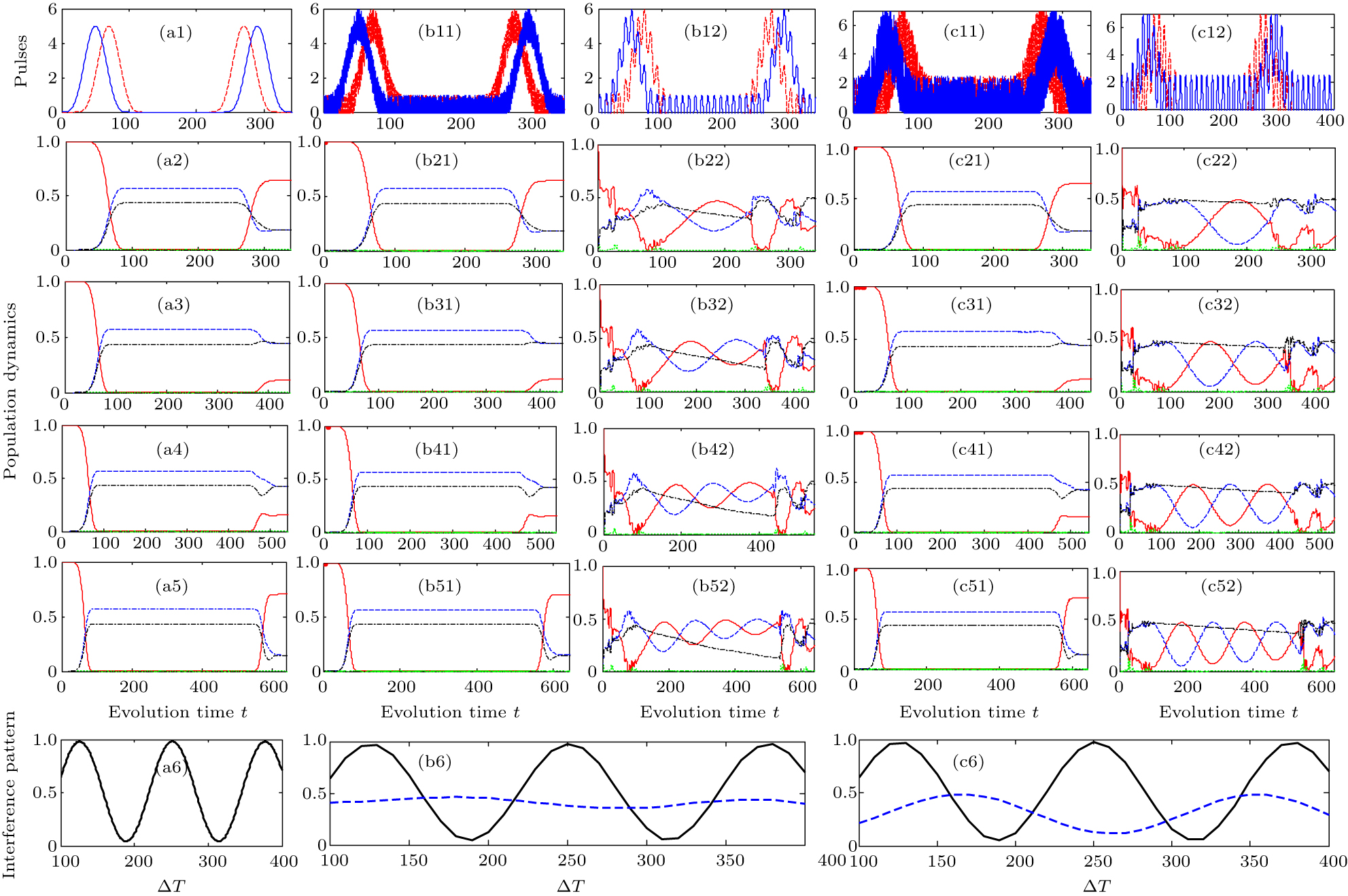
Fig. 5. (a1) The original laser pulses without fluctuations and Δ T = 100, the same as shown in Fig. 1(b). (a2)–(a5) The corresponding population dynamics of Pg0(t) (red-solid), Pgr (blue-dashed), Pgd (black-dash-dotted), Per (green-dotted) under different hold time Δ T = 100,200,300,400, respectively. The detection time is set to be tdet = 2 (T + τ) + Δ T after pulses. (a6) A high-contrast interference pattern vs. the hold time Δ T by detecting the final population Pg0(∞). Similarly, case (b) shows the modified laser pulses  (red) and
  (blue) as well as the population dynamics, under stochastic fluctuations (second column) and sinusoidal modulation (third column), in which the modulation amplitude δΩp(s)(t) ∈ [–δΩ,δΩ], and δΩ = 0.2Ω0. The resulting interference pattern is comparably shown in (b6) with the cases of stochastic fluctuations (black-solid) and sinusoidal modulation (blue-dashed). Case (c) represents similar results with respect to case (b), except for a stronger modulation amplitude δΩ = 0.5Ω0. Here δ = 0.05, Ω0 = 5.0 are constant.
Download figure:
Standard imageNevertheless, if the perturbation is replaced by a regular sinusoidal modulation, as plotted in Figs. 5(b12) and 5(c12) with the same amplitudes δΩ/Ω0 = 0.2 and 0.5, we observe that the population dynamics is strongly impacted by the sinusoidal modulation, resulting in a thorough breakdown of the interference pattern (blue-dashed curves in Figs. 5(b6) and 5(c6)). Because it is difficult to exactly overcome the phase accumulation for a sinusoidal modulation during the evolution. We could expect a more visible interference output if the modulation frequency ω is increased. Since a larger ω leads to a fast modulation to the pulses that is more similar to a stochastic perturbation, the resulting interference quality will be improved.
To our knowledge, a typical external noise is stochastic not regular. Therefore, our protocol can deservedly exhibit robust stability towards arbitrary stochastic fluctuations from the laser intensity noise, preserving a high-contrast interference output.
3.2. Imperfect stability from Zeeman splitting states
In fact, the Zeeman splitting δ can also be disturbed due to the instability of the external magnetic field, probably suffering from a stochastic shift δ' to the splitting level. In that case, for the R-STIRAP path, the two-photon resonance condition is perturbed by a stochastic detuning δ', leading to the Hamiltonian  described by

and for D-STIRAP the level shift turns to be δ + δ', and its Hamiltonian  becomes

Intuitively such fluctuation will influence the population transfer along R-STIRAP and D-STIRAP paths simultaneously, lowering the conversion efficiency. However, we show that due to the randomness of fluctuations that can be almost overcome on average, our scheme is able to maintain an observable quantum interference pattern even under very strong energy-level disturbance. Relevant numerical results are summarized in Fig. 6, where the time-dependent population transfer Pg0(t) along each STIRAP path as well as the final interference pattern are separately displayed. In the calculation, the random number δ' is created within the range of [–0.5,0.5]δ by using the random number generator in Matlab. Figures 6(a1) and 6(a2) show two sets of random numbers δ'(t) for δ = 0.05 and 0.5 respectively. When the Zeeman splitting δ = 0.05(small), our results verify that such fluctuation δ' arises no visible changes, as represented in Figs. 6(b1)–6(d1) and 6(b2)–6(d2). Our findings show that the population dynamics for both R-STIRAP and D-STIRAP are perfectly agreeable, giving rise to a high-contrast quantum interference, see Figs. 6(d1) and 6(d2).

Fig. 6. (a1) The random number δ' with time t. Here δ = 0.05 and δ'/δ ∈ [–0.5,+0.5]. (b1)–(b2) The population dynamics Pg0(t) of R-STIRAP and D-STIRAP without perturbation, i.e., δ' = 0. (c1)–(c2) are similar to (b1)–(b2) except for δ'/δ ∈ [–0.5,+0.5]. Insets of (c1)–(c2) amplify the population variation of Pg0(∞) within the range of t ∈ [300,600]. (d1)–(d2) The interference pattern without or with stochastic fluctuations δ' from unstable hyperfine splitting states. (a2)–(d4) present similar results yet with a stronger stochastic fluctuation δ = 0.5 and δ'/δ ∈ [–0.5,+0.5]. Other parameters are Ω0 = 5.0, Δ T = 100.
Download figure:
Standard image{Moreover, if the original splitting energy is relatively large, e.g., δ = 0.5, yet keeping δ < Ω0, the time-dependent population dynamics Pg0(t) for individual R-STIRAP and D-STIRAP paths still does not change much under the influence of stronger fluctuations. However, the interference is totally destroyed. This fact can be understood by combining with Fig. 4(c), in which the interference visibility emerges a clear reduction if |δ| is enhanced. Because the coherence between R-STIRAP and D-STIRAP decreases as δ increases. A limitation lies in if δ is far off-resonance that two STIRAP paths separately perform an individual population transfer. To this end, no interference will emerge between them.
All in all, our protocol shows robust stability against stochastic fluctuations from the unstable energy shifts. Even if the two-photon resonance can not be preserved perfectly, the production of quantum interference pattern is still robust. The only way for breaking such quantum interference is making two-path decoherence, e.g., via a bigger ground energy splitting δ. Therefore, once δ is appropriately chosen, the stability of our protocol against fluctuations is robust.
4. Nearby excited levels
Before ending, we extend our model to a generalized multi-level system with more than one neighboring excited states. To this end, the D-STIRAP will follow the path of |g0〉 ⇄ |ed
n〉 ⇄ |gd〉, in which states |ed
n〉 (n = 1,2,...) stand for the nearby multiple excited states. Δn
is introduced to express the interstate energy spacing and consequently the detuning of each state |ed
n〉 is described by  . Therefore, the systematic Hamiltonian
  [Eq. (1)] should be replaced by
  in which the additional term
  stands for the auxiliary energy shift caused by the nearby excited states |ed
n〉. For n = 1,
stands for the auxiliary energy shift caused by the nearby excited states |ed
n〉. For n = 1,  and for n = 2,
  . By inserting
  into the master equation, we are able to solve the interference pattern as expected. Note that the spontaneous dissipation from all excited states |er〉 and |ed
n〉 should be considered. Here Δj
= Δ is assumed for simplicity.
into the master equation, we are able to solve the interference pattern as expected. Note that the spontaneous dissipation from all excited states |er〉 and |ed
n〉 should be considered. Here Δj
= Δ is assumed for simplicity.
Figure 7 presents the variation of pattern visibility (blue) as well as pattern frequency (red) when more excited levels are involved. Here we take |ed1〉 and |ed2〉 as examples, which means it exists two D-STIRAP routes by following |g0〉 ⇄ |ed1〉 ⇄ |gd〉 and |g0〉 〉 |ed2〉 〉 |gd〉. The corresponding one-photon detunings are Δ1 and Δ1 + Δ2. A quick search of Fig. 7(a) arises a prediction that the visibility grows under the help of multiple middle levels. For a reduced four-level model with |er〉, we find the final visibility is only vis = 0.9191 (not shown). However, the presence of multi-levels adds auxiliary D-STIRAP paths. e.g., for n = 1 vis ≈ 0.92 that slightly varies with Δ, and for n = 2 the combination of |g0〉 ⇄ |ed1〉 ⇄ |gd〉 and |g0〉 ⇄ |ed2〉 ⇄ |gd〉 has raised the pattern vis to 0.9617 (blue-dashed). An additional merit lies in the persistence of high visibility no matter how to change its spacing Δ. That fact strongly verifies the robustness of our scheme under the influence of nearby excited levels. Note that we choose Δ ∈ [1,100] here for meeting the validity of the four-level model as proposed in Subsection 2.1, but our conclusion can be applied for a system with more hyperfine excited levels. In addition, the oscillation frequency of the interference pattern also keeps unvaried in different multi-level schemes, and perfectly agrees with the theoretical formula f = δ/2π ≈ 0.008 (δ = 0.05) as expected. Figures 7(b1)–7(b3) and 7(c1)–7(c3) fully represent the high-contrast quantum interference pattern under n = 1 and 2 for different detunings Δ values, which perfectly agrees with our theoretical analysis.

Fig. 7. (a) Left: Visibility vis (blue) of the interference pattern vs. one-photon detuning Δ. Here Δn = Δ and the exemplified cases with n = 1,2 (solid and dashed) are shown. Right: A common pattern frequency f (red) vs. Δ. Inset describes an extensive energy-level structure with multiple nearby excited states |ed n〉 separated by detunings Δn . (b1)–(b3) and (c1)–(c3) show the interference pattern under the cases of n = 1 and n = 2, respectively. Different level spacings Δ = (1,10,100) are calculated.
Download figure:
Standard imageFinally, we carry out a brief numerical estimation based on relevant experimental parameters of 87Rb atoms. Choosing typical energy levels such as |g0〉 = |5S1/2,F = 1,mF = –1〉, |gr〉 = |5S1/2,F = 2,mF = 0〉, |gd〉 = |5S1/2,F = 2,mF = 1〉 for ground states, and |er〉 = |5P3/2,F = 2〉 for the resonant excited state, which determines the decay rate is about Γ/2π = 6.0 MHz. In the reduced four-level model, during the hold time between Δ T ∈ [5.3, 31.8] μs we can set a common laser amplitude Ω0/2π = 30 MHz with its pulse length T = 2.65 μs and delay time τ = 0.53 μs. Note that the hyperfine splitting energy δ can be adjusted by an external magnetic field. Here if δ = 1.88 MHz corresponding to δ/Γ = 0.05 as adopted in our calculation, we find a round-trip STIRAP interference gives to the pattern visibility about 0.9191 accompanied by a fast oscillating frequency f = 210 kHz. To improve the visibility of interference pattern, one way is to adjust the splitting energy δ to be smaller. For example, when δ = 264 kHz corresponds to δ/Γ ≈ 0.007, the resulting visibility can be increased to 0.9813 yet suffering from a relatively slow oscillating frequency f ≈ 29.4 kHz. To this end, we have verified that such a high-contrast quantum interference coming from STIRAP interfering can robustly exist in a practical atomic system.
5. Conclusion
To conclude, the high-quality quantum interference effect can enhance the accuracy of quantum measurement for facilitating an accurate control of hyperfine structure or phase sensitivity. Guided by recent experimental facts we thoroughly investigate the formation of a high-contrast quantum interference effect with robust stability, which essentially benefits from the intrinsic advantages of the STIRAP technology. First, the scheme exhibits a clear interference pattern with very high visibility, supporting a quantitative and non-destructive detection of hyperfine energy without destroying the coherence of quantum states. Second, the production of quantum interference has a well-preserved stabilization against any stochastic fluctuations coming from the laser intensity noise and the small shift of two-photon resonance. These facts are intrinsically enabled by a stable coherent population transfer in STIRAP, which is greatly isolated from external fluctuations. Third, the robustness of our scheme is also revealed when more excited states are involved in a real implementation, facilitating an enhancement for the interference visibility due to the assistance from multiple D-STIRAP paths. This protocol takes an important step towards the development of a stabilized STIRAP atom interferometry with ultrahigh precision for future experimental explorations.
Footnotes
- *
Project supported by the National Natural Science Foundation of China (Grant Nos. 11474094 and 11104076) and the Science and Technology Commission of Shanghai Municipality, China (Grant No. 18ZR1412800).