The Field-Frequency Lock for Fast Field Cycling Magnetic Resonance: From NMR to MRI
 G. Galuppini
 L. Magni1
 - 1Identification and Control of Dynamic Systems Lab, Department of Civil Engineering and Architecture, University of Pavia, Pavia, Italy
- 2Stelar s.r.l., Mede, Italy
Magnetic field stability plays a fundamental role in Nuclear Magnetic Resonance (NMR) and Magnetic Resonance Imaging (MRI) experiments, guaranteeing accuracy and reproducibility of results. While high levels of stabilization can be achieved for standard NMR techniques, this task becomes particularly challenging for Fast Field Cycling (FFC) NMR and MRI, where the main magnetic field is switched to higher or lower levels during the pulse sequence, and field stabilization must be guaranteed within a very short time after switching. Recent works have addressed the problem with rigorous tools from control system theory, proposing a model based approach for the synthesis of magnetic field controllers for FFC-NMR. While an experimental proof of concept has underlined the correctness of the approach for a complete FFC-NMR setup, the application of the novel, model based Field-Frequency Lock (FFL) system to a FFC-MRI scanner requires proper handling of field encoding gradients. Furthermore, the proof of concept work has also stressed how further advances in the hardware and firmware could improve the overall performances of the magnetic field control loop. The main aim of this perspective paper is then discussing the key challenges that arise in the development of the FFL system suitable for a complete MRI scanner, as well as defining possible research directions by means of preliminary, simulated experiments, with the final goal of favoring the development of a novel, model based FFL system for FFC-MRI.
1 Introduction
Fast Field Cycling (FFC) Nuclear Magnetic resonance (NMR) and Magnetic Resonance Imaging (MRI) are two high-end techniques that exploit the dependence of the spin-lattice relaxation rate
• a high polarization field
• a low relaxation magnetic field
• an acquisition field
As magnetic resonance techniques, FFC-NMR and MRI require a very precise and stable acquisition field. Due to the tight bound between magnetic field strength and resonance frequency, each magnetic field disturbance results in a perturbation of the resonance frequency and, ultimately, in noise affecting the experimental data. In addition, the FFC experimental design requires the desired level of field accuracy to be guaranteed as soon as possible, after the relaxation/acquisition magnetic field switch. As a matter of fact, the later the actual signal acquisition starts after the magnetic field reaches the acquisition value, the less information about the dependence of the spin-lattice relaxation rate on the magnetic field magnitude is encoded in the acquired signal [1, 2].
1.1 The Challenge of Field Stabilization in Fast Field Cycling Magnetic Resonance
In standard FFC setups, a magnetic field control loop, based on direct magnetic field measurements, takes care of the tracking of the field reference profile, but may not provide the desired field regulation and disturbance rejection performances during the acquisition phase [3, 4]. The main issue of this approach resides in the lack of a proper magnetic field sensor, which should be able to provide high resolution and quick response over a wide range of measured values, while being sufficiently compact and suitable to be placed very close to (virtually inside) the measured NMR sample [5, 6]. Furthermore, the need for field cycling capabilities does not allow for the application of the typical approaches adopted to generate stable magnetic fields, such as the use of permanent or superconducting magnets [7, 8]. The NMR Field-Frequency Lock (FFL) is another common approach to reduce magnetic field oscillations in NMR experiments [5, 6, 9, 10, 11, 12, 13, 14]. FFL systems exploit the dependence of the NMR signal on the magnetic field, and obtain an indirect but very precise measurement of magnetic field fluctuations from a parallel NMR experiment, called the lock experiment. To avoid cross-talk between main and lock experiments, the two are performed targeting different nuclear species. Very often, it is possible to construct samples containing the nuclei of interest for both the main and the lock experiments, obtaining measurements of the magnetic field at the exact position of the sample [9, 15, 16, 17]. The standard implementation of the FFL is the phase Locked Loop (PLL) [8, 10, 18]: the lock signal is first processed to extract its main frequency, which is compared with the reference one to generate an error signal. The error eventually feeds into a regulator that computes the necessary magnetic field adjustment to steer the field error, and thus the frequency error, to zero. However, the PLL control scheme is only effective for the compensation of slow magnetic field drifts, such as thermal drift effects, and does not allow for the rapid field stabilization [5] required in the FFC context. A reliable estimation of the frequency of the lock signal requires in fact a sufficient number of samples, as well as a sufficient Signal to Noise (SNR) ratio. Consequently, the control action can be computed and applied to the system only at a relatively low frequency, resulting in long closed-loop settling times and poor high frequency disturbance rejection capabilities [19, 20].
1.2 State-of-the-Art Solutions for Field Stabilization in Fast Field Cycling Magnetic Resonance
To overcome the above limitation, the FFL approach can be adapted as discussed in some recent works. References [5, 6] demonstrate that a series of low power, high repetition rate Radio Frequency (RF) pulses, which bring the sample in a Steady State Free Precession (SSFP) regime ([15, 21, 22, 23, 24]), generate a continuous NMR signal measuring the field deviation from the resonant one. In the reminder of this work, the SSFP NMR signal will be denoted as
While delivering promising results, a more specific analysis of the experiments presented in [25] can highlight a series of issues that may act as limiting factors for the FFC-FFL performances. Therefore, this perspective paper aims at discussing such issues and proposing possible research directions, based on preliminary simulated experiments. Moreover, the final goal of this research is the integration of a FFL into a novel FFC-MRI scanner, as the one described in [28]. Field stabilization of standard MRI scanners represents a great challenge itself, due to the spatial distribution of the magnetic field and the presence of field-encoding gradients. Only few works address this problem, adopting both feedforward [29, 30, 31, 32] or feedback control methods [13, 33, 34, 35]. However, none of them is currently examining solutions for FFC-MRI scanners. Therefore, this work also aims at discussing possible approaches to adapt the state-of-the-art field stabilization strategies for FFC to handle the presence of field-encoding gradients characterizing FFC-MRI scanners, thus moving a step forward toward the design of a suitable FFL system for FFC-MRI.
2 Discussion
The Discussion section of this work addresses the key issues in the implementation of a FFL system for FFC-NMR and MRI, as well as possible ways to face them. In particular, Figure 1A depicts the overall FFL scheme for FFC-MRI proposed in this work. The main enhancements to its components are analyzed in the reminder of this Section, by means of simulated experiments. The simulation environment models all the main components of the NMR lock experiment, consisting of magnet and power supply, NMR physics, transmission and acquisition chains, linear regulator. The simulation environment is discussed in detail in [6, 25].
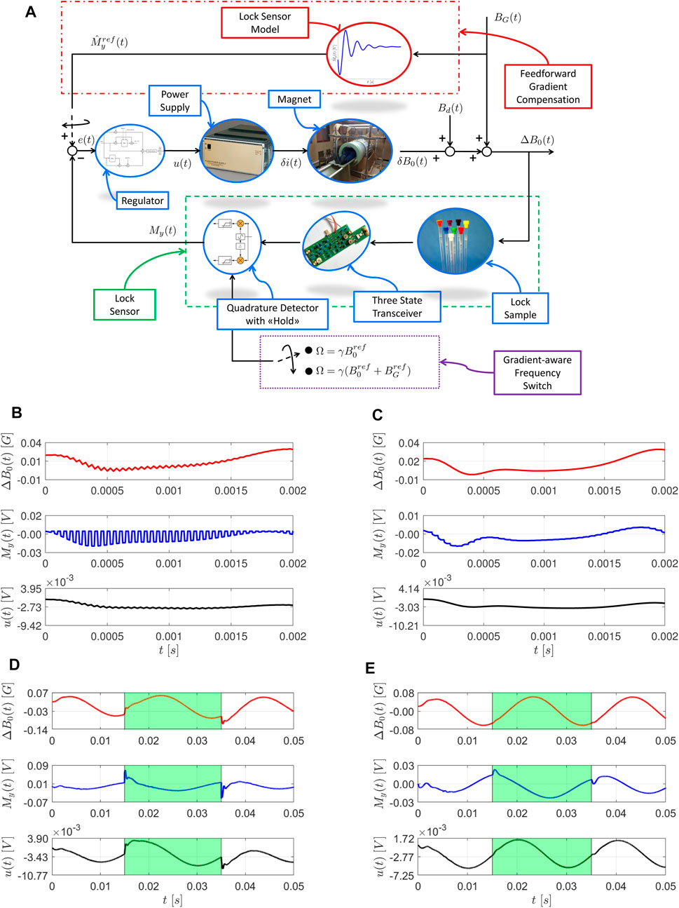
FIGURE 1. Enhanced FFL control scheme for MRI and preliminary closed-loop simulations. Simulations are performed with a virtual version of the Copper Sulfate sample from [25]. (A) The control loop, including power supply, magnet, lock sample, three state transceiver, quadrature detector with hold procedure and a linear regulator. The cascade sample-transceiver-detector plays the role of lock magnetic field sensor (green, dashed box). The main signals in the loop are the voltage control action
2.1 Field Frequency Lock Hardware and Firmware Improvements
The proposed FFL can benefit from the hardware and firmware enhancements described in the reminder of this Section, in case of application to both FFC-NMR and MRI setups.
2.1.1 Receiver Hold Procedure
As previously introduced, the main step allowing to overcome the use of PLLs and improve the FFL performance is the generation of a continuous NMR signal, acting as magnetic field disturbance measure. To this end, the lock sample must be stimulated with low power RF pulses, with a repetition time T such that
2.1.2 Three-State Transceiver Design
Even when applying low power pulses, due to field inhomogeneity, the sample
1.transmit: a high Q factor is engaged to handle high transmission power
2.Q-damping: a low Q factor is engaged to quickly discharge the coil;
3.receive: a high Q factor is engaged again to provide high SNR.
As depicted in Figure 2A, online adaptation of the probe Q factor is obtained by connecting the probe to a damping resistor during the Q-damping state. The three-state transceiver operation state is determined by a three-way switch that connects the probe to the transmitter, the damping resistor and the receiver, respectively. An example of logic circuit to control the state of the transceiver is depicted in Figure 2B. Note that, while in the example the logic circuit is designed to be driven by three lines, it can be straightforwardly adapted to a two lines framework. Finally, to protect the receiver during the high power transmission, the circuit includes protection diodes and preamp disabling during transmit and Q damping states. The proposed three-state transceiver design allows for impedance matching and adjustable gain, and provides filtering of out-band noise and overall low noise amplification, as underlined by preliminary simulations performed with models of commercially available discrete components. In particular, the plots reported in Figures 2C–E, which depict the current through the RF coil for a
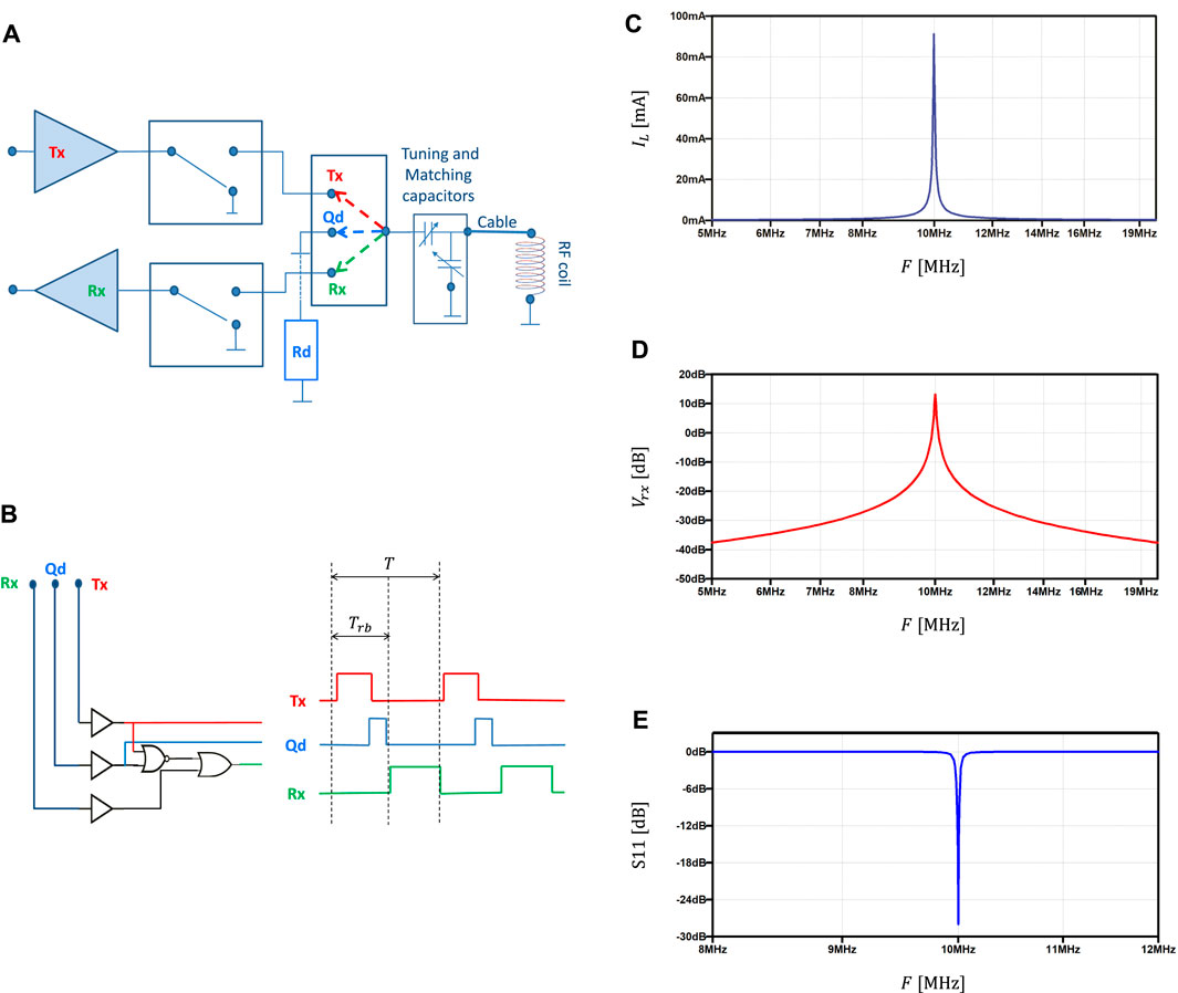
FIGURE 2. Three state transceiver. (A) Conceptual block scheme including transmitter, receiver, Q damping resistor, three way switch, tuning and matching capacitors and RF coil. (B) Example of logic circuit (three command lines) driving the three state transceiver over transmit, Q-damping and receive states at each RF pulse repetition time T. The receiver blank time
2.2 Handling of MRI Field Encoding Gradients
Despite the enhancements discussed in the previous section, the application of the FFL system to a FFC-MRI scanner unavoidably requires explicit handling of field gradients. From the FFL perspective, each magnetic field moving the resonance condition from the original, resonance one represents a disturbance to be rejected. In case of field gradients, the lock sensor would detect a field disturbance and try to restore the resonance condition corresponding to no gradient active, possibly spoiling the results of the encoding procedure. In a worst case scenario, this may spoil the results of the whole experiment. Preliminary simulations suggest two possible ways to mitigate this problem, and retain some of the benefits of the FFL system during the application of field gradients: the Gradient-Aware Frequency Switch (GAFS) and the Feedforward Gradient Compensation (FGC) procedures. Both techniques are based on the hypothesis that the field deviation introduced with gradients is known (with sufficient precision) at the lock sensor site. Since gradient generation is controlled by the MRI equipment, this hypothesis is typically reasonable.
2.2.1 Gradient-Aware Frequency Switch Procedure
The GAFS procedure, depicted in Figure 1A, consists in the online switch of the lock sensor receiver frequency,
2.2.2 Feedforward Gradient Compensation Procedure
The FGC procedure, depicted in Figure 1A, aims at reducing the impact of such sudden reference change, by dynamically adapting the closed-loop reference according to a dynamic model of the lock sensor response. Note that, as a first approximation, this model can coincide with the linear model used for the model based tuning of the FFL regulator, and is therefore available at no additional effort. While preliminary simulations (see Figure 1E for an example) highlight the benefit of the approach, it must be remarked that, due to the use of a linear model for the dynamic lock sensor response, FGC can only be applied for gradients whose intensity,
2.3 Concluding Remarks and Open Issues
Based on the results presented in the recent literature regarding FFL systems for FFC-NMR, this perspective article highlighted and discussed some key problems and possible ways to improve the FFC-FFL performances, and allow its implementation on a FFC-MRI scanner. Since preliminary simulations suggested that the proposed approaches can provide promising results, the future work will focus on their practical implementation and experimental evaluation. Moreover, while this work focused more on issues related to hardware and firmware enhancements, it is worth mentioning in this concluding section that room for further improvement can also be found in the engineering of a control sample whose characteristic time constants and dynamic behavior could allow for even faster regulation of the magnetic field [5, 25]. Finally, the tuning of the regulator could be optimized and automatized, by adapting optimization-based procedures suitable to handle systems characterized by very complex high frequency behavior [36].
Data Availability Statement
The original contributions presented in the study are included in the article/supplementary material, further inquiries can be directed to the corresponding author.
Author Contributions
Conceptualization: GG, LM and GF; writing—original draft preparation: GG writing—review and editing: LM and GF All authors have read and agreed to the published version of the manuscript.
Funding
This project has received funding from the European Union’s Horizon 2020 research and innovation program under grant agreement No 668119 (project “IDentIFY”).
Conflict of Interest
Author GF is company director of Stelar s.r.l.
The remaining authors declare that the research was conducted in the absence of any commercial or financial relationships that could be construed as a potential conflict of interest.
Acknowledgments
The Authors would like to thank the whole Stelar group for providing great insight and expertize in the development of this research.
References
1. Ferrante G, Sykora S. Technical Aspects of Fast Field Cycling. Adv Inorg Chem (2005) 57:405–70. doi:10.1016/s0898-8838(05)57009-0
2. Kimmich R. Field-cycling NMR Relaxometry: Instrumentation, Model Theories and Applications. London, UK: Royal Society of Chemistry) (2018).
3. Roque A, Maia J, Margato E, Sousa DM, Marques G. Control and Dynamic Behaviour of a Ffc Nmr Power Supply. In: IECON 2013-39th Annual Conference of the IEEE Industrial Electronics Society (IEEE), 10-13 November, Vienna, Austria (2013). p. 5945–50.
4. Roque A, Sousa DM, Sebastião P, Margato E, Marques G. Ffc Nmr Relaxometer with Magnetic Flux Density Control. Jlpea (2019) 9:22. doi:10.3390/jlpea9030022
5. Samra J. A Field-Frequency Lock Implemented with a Sampled-Data Feedback Control Algorithm Derived from a Small-Signal NMR Model. Master’s thesis. University Park, PA: The Pennsylvania State University (2008).
6. Galuppini G, Toffanin C, Raimondo DM, Provera A, Xia Y, Rolfi R, et al. Towards a Model-Based Field-Frequency Lock for Nmr. IFAC-PapersOnLine (2017) 50:13020–5. doi:10.1016/j.ifacol.2017.08.1999
7. Maly T, Bryant J, Ruben D, Griffin RG. A Field-Sweep/field-Lock System for Superconducting Magnets-Application to High-Field EPR. J Magn Reson (2006) 183:303–7. doi:10.1016/j.jmr.2006.09.012
8. Hoult DI, Richards RE, Styles P. A Novel Field-Frequency Lock for a Superconducting Spectrometer. J Magn Reson (1969) (1978) 30:351–65. doi:10.1016/0022-2364(78)90106-3
10. Jiang D, Chen H, Chen Z, Zheng Z. The Digital Field-Frequency Lock System of High-Resolution Nmr Spectrometer. In: Electrical and Control Engineering (ICECE), 2010 International Conference on IEEE, 25-27 June, Wuhan, China (2010). p. 2328–31.
11. Li M, Schiano JL, Samra JE, Shetty KK, Brey WW. Reduction of Magnetic Field Fluctuations in Powered Magnets for Nmr Using Inductive Measurements and Sampled-Data Feedback Control. J Magn Reson (2011) 212:254–64. doi:10.1016/j.jmr.2011.05.010
12. Yanagisawa Y, Nakagome H, Hosono M, Hamada M, Kiyoshi T, Hobo F, et al. Towards Beyond-1 GHz Solution NMR: Internal 2H Lock Operation in an External Current Mode. J Magn Reson (2008) 192:329–37. doi:10.1016/j.jmr.2008.03.015
13. Henry P-G, van de Moortele P-Fo., Giacomini E, Nauerth A, Bloch G. Field-frequency Locked In Vivo Proton Mrs on a Whole-Body Spectrometer. Magn Reson Med (1999) 42:636–42. doi:10.1002/(sici)1522-2594(199910)42:4<636::aid-mrm4>3.0.co;2-i
14. Chen S, Xu L, Wang H, Dai S. Field-frequency Lock Approach for 21.3-mhz High-Performance Nmr Relaxation Analyzer. AIP Adv (2018) 8:075327. doi:10.1063/1.5038138
15. Elster A. Questions and Answers in Magnetic Resonance Imaging. Maryland Heights, Missouri: Mosby Inc (1994).
16. Hornak JP. The Basics of NMR. Rochester, NY: Rochester Institute of Technology, Center for Imaging Science (1997).
17. Jacobsen NE. NMR Spectroscopy Explained: Simplified Theory, Applications and Examples for Organic Chemistry and Structural Biology. Hoboken, New Jersey: John Wiley & Sons (2007).
18. Kan S, Gonord P, Fan M, Sauzade M, Courtieu J. Automatic NMR Field‐frequency Lock-Pulsed Phase Locked Loop Approach. Rev Scientific Instr (1978) 49:785–9. doi:10.1063/1.1135615
19. Seborg DE, Mellichamp DA, Edgar TF, Doyle FJ. Process Dynamics and Control. Hoboken, NJ: John Wiley & Sons (2010).
21. Carr HY. Steady-state Free Precession in Nuclear Magnetic Resonance. Phys Rev (1958) 112:1693–701. doi:10.1103/physrev.112.1693
22. Patz S. Some Factors that Influence the Steady State in Steady-State Free Precession. Magn Reson Imaging (1988) 6:405–13. doi:10.1016/0730-725x(88)90477-8
23. Gyngell ML. The Steady-State Signals in Short-Repetition-Time Sequences. J Magn Reson (1969) (1989) 81:474–83. doi:10.1016/0022-2364(89)90083-8
24. Bagueira de Vasconcelos Azeredo R, Colnago LA, Engelsberg M. Quantitative Analysis Using Steady-State Free Precession Nuclear Magnetic Resonance. Anal Chem (2000) 72:2401–5. doi:10.1021/ac991258e
25. Galuppini G, Toffanin C, Raimondo D, Provera A, Xia Y, Rolfi R, et al. Towards a Model-Based Field-Frequency Lock for Fast-Field Cycling Nmr. Appl Magn Reson (2019) 1–23.
26.[Dataset] Stelar Website. Available from: https://www.stelar.it/ (Accessed 14 June 2021).
27.[Dataset] Ieco Website. Available from: http://www.ieco.fi/ (Accessed 14 June 2021).
28. Broche LM, Ross PJ, Davies GR, MacLeod MJ, Lurie DJ. A Whole-Body Fast Field-Cycling Scanner for Clinical Molecular Imaging Studies. Sci Rep (2019) 9:10402–11. doi:10.1038/s41598-019-46648-0
29. Juchem C, Nixon TW, Diduch P, Rothman DL, Starewicz P, De Graaf RA. Dynamic Shimming of the Human Brain at 7 T. Concepts Magn Reson (2010) 37B:116–28. doi:10.1002/cmr.b.20169
30. Bhogal A, Versluis M, Koonen J, Siero JCW, Boer VO, Klomp D, et al. Image-based Method to Measure and Characterize Shim-Induced Eddy Current fields. Concepts Magn Reson (2013) 42:245–60. doi:10.1002/cmr.a.21290
31. Fillmer A, Vannesjo SJ, Pavan M, Scheidegger M, Pruessmann KP, Henning A. Fast Iterative Pre‐emphasis Calibration Method Enabling Third‐order Dynamic Shim Updated fMRI. Magn Reson Med (2016) 75:1119–31. doi:10.1002/mrm.25695
32. Vannesjo SJ, Dietrich BE, Pavan M, Brunner DO, Wilm BJ, Barmet C, et al. Field Camera Measurements of Gradient and Shim Impulse Responses Using Frequency Sweeps. Magn Reson Med (2014) 72:570–83. doi:10.1002/mrm.24934
33. Sinanna A, Bermond S, Donati A, Gros P, Hugon C, Jacquinot J-F, et al. Field Stabilization of an Mri Magnet Operating in Driven Mode. IEEE Trans Appl Supercond (2009) 19:2301–4. doi:10.1109/tasc.2009.2018105
34. Dürst Y, Wilm BJ, Dietrich BE, Vannesjö S, Pruessmann KP. Real-time Shim Feedback for Field Stabilization in Human Mri Systems. Melbourne, Australia: Scientific Meeting of the International Society for Magnetic Resonance in Medicine (2012).
35. Duerst Y, Wilm BJ, Dietrich BE, Vannesjo SJ, Barmet C, Schmid T, et al. Real-time Feedback for Spatiotemporal Field Stabilization in Mr Systems. Magn Reson Med (2015) 73:884–93. doi:10.1002/mrm.25167
Keywords: FFC-NMR, FFC-MRI, field-frequency lock, stability, magnetic field
Citation: Galuppini G, Magni L and Ferrante G (2021) The Field-Frequency Lock for Fast Field Cycling Magnetic Resonance: From NMR to MRI. Front. Phys. 9:688479. doi: 10.3389/fphy.2021.688479
Received: 30 March 2021; Accepted: 08 June 2021;
Published: 22 June 2021.
Edited by:
Lionel Marc Broche, University of Aberdeen, United KingdomReviewed by:
Harish Kittur, VIT University, IndiaDuarte Mesquita Sousa, University of Lisbon, Portugal
Copyright © 2021 Galuppini, Magni and Ferrante. This is an open-access article distributed under the terms of the Creative Commons Attribution License (CC BY). The use, distribution or reproduction in other forums is permitted, provided the original author(s) and the copyright owner(s) are credited and that the original publication in this journal is cited, in accordance with accepted academic practice. No use, distribution or reproduction is permitted which does not comply with these terms.
*Correspondence: G. Galuppini, giacomo.galuppini01@ateneopv.it