Design of a Multilayer Dual-Band Balanced Bandpass Filter on a Circular Patch Resonator
 Yanhui Xu
 Zhengkang Liu
 Shiyan Wang
 Wanchun Tang2
 - 1Department of Electrical and Computer Engineering, Faculty of Science and Technology, University of Macau, Macau, China
- 2School of Electrical and Automation Engineering, Nanjing Normal University, Nanjing, China
- 3College of Medicine and Biological Information Engineering, Northeastern University, Shenyang, China
This letter presents a novel multilayer dual-band balanced bandpass filter (BPF) design by using two perturbed circular patch resonators. The TM11 mode and TM21 mode of the resonator with odd-symmetric field distributions are explored to realize the desired differential-mode (DM) transmission and common-mode (CM) suppression. Two circular patches are properly coupled in the back-to-back form to realize a dual-passband balanced response by virtue of coupling apertures etched on the ground. In addition to the internal coupling, the above apertures are also further utilized for the undesired degenerate mode harmonic suppression. Besides, slot perturbations on the patch are introduced to perturb the TM21 resonant mode to independently adjust the center frequency of the higher passband, while the lower passband remains almost unchanged. Thus, two passbands can be flexibly controlled by simultaneously tuning the above slots and size of the patch. For validation, a dual-band balanced BPF prototype is implemented. The results indicate 18 and 26% wide fractional bandwidths centered at 5.5 and 7.5 GHz with return loss higher than 20 dB under DM operation and CM suppression higher than 40 dB over an ultra-wide frequency band.
Introduction
Balanced filters play key roles in modern wireless communication systems, attributing to their superior immunity to the electromagnetic interference and environmental noise [1]. In the meantime, great development of modern wireless communication systems brings out an increased requirement for dual-band operations. To the end, dual-band balanced bandpass filters (BPFs) are desired.
Accordingly, much efforts have been made to explore a variety of high-performance dual-band balanced BPFs by using different transmission line structures, such as planar microstrip transmission line resonators [2–5], substrate-integrated waveguide (SIW) resonators [6–9], and dielectric resonators (DRs) [10]. On the contrary, the patch-type resonators are attracting much attention in balanced BPF designs due to their superior advantages of higher power handling capability and lower loss over the transmission line–based resonators and simpler and more straightforward analysis and design compared with the SIW and DR forms. However, to the best of our knowledge, only limited works have been carried out on design of single-band balanced BPFs, e.g., square patch resonator–based balanced BPFs [11–13] and triangular patch resonator–based balanced BPFs [14–16]. How to design a dual-band patch balanced BPF is still rarely reported and remains challenging.
This letter is aimed at presenting a new dual-band balanced BPF design on a circular patch resonator. For this purpose, the TM11 mode and TM21 mode resonant properties of a circular patch are carefully analyzed and investigated with both differential-mode (DM) excitation and common-mode (CM) excitation. Two vertically coupled circular patches, via proper coupling apertures etched on the common ground, are explored to realize two passbands under DM operation. Furthermore, slot perturbations on the patch are designed to adjust the frequency ratio of the two passbands and attain high CM suppression. In order to demonstrate the design concept, a circular patch dual-band balanced filter prototype was designed, manufactured, and tested. Measured and simulated results well coincide with each other.
Design and Analysis of the Proposed Dual-Band Balanced Filter
Figures 1A–E describe the configuration of the proposed dual-band balanced BPF. Two layers of RO4003C substrates (εr = 3.55, h = 0.508 mm, and tanδ = 0.0027) are used. Two differential input ports (Ports 1 and 1′) are placed at the top layer, while two output ports (Ports 2 and 2′) are at the bottom layer. Two coupling apertures of length l2 and width w2 are arranged along the main diagonal line (A–B) on the square common ground of Figure 1D. Besides, two perturbation slots with length l1 and width w1 are placed along the diagonal line (C–D) of a circular patch with radius r as shown in Figures 1C,E. The dual-band response of the proposed balanced BPF is realized by the utilization of two diagonal modes: TM11 mode (Mode 1) and TM21 mode (Mode 3), in the patch resonator. In this context, the first DM passband is made up of a pair of TM11 modes (Mode 1), while the second DM passband is formed by two TM21 modes (Mode 3) from the two top- and bottom-layer patches, respectively. Detailed working mechanisms are illustrated as follows.
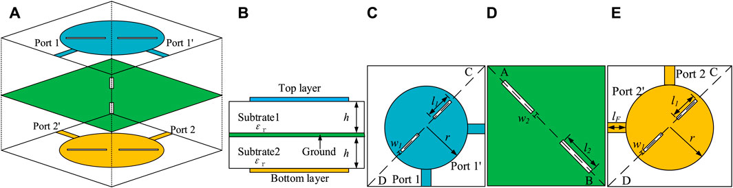
FIGURE 1. (A) 3D view of the proposed dual-band balanced filter, (B) side view, (C) top layer, (D) middle layer, and (E) bottom layer.
Figure 2 and Figure 3 indicate simulated electrical and magnetic fields of the first three resonant modes in the circular patch: a pair of degenerate TM11 modes (Mode 1 and Mode 2) and TM21 mode (Mode 3), respectively. As observed in Figure 2, the electrical-field patterns of these modes are odd-symmetric inside the patch. In other words, almost same intensity and opposite direction can be found with respect to the corresponding symmetric plane. Therefore, when input ports 1 and 1′ are injected with DM signals, the fields of the TM11 mode (Mode 1) and TM21 mode (Mode 3) can be simultaneously excited in the top-layer patch. Meanwhile, the magnetic-field intensity around regions (Area 1 and Area 3) in Figure 3 is high for both the TM11 mode (Mode 1) and the TM21 mode (Mode 3).
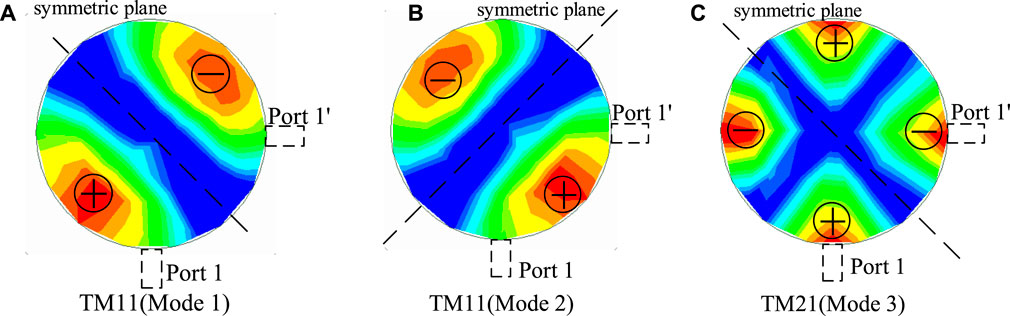
FIGURE 2. Simulated E-fields of the resonant modes in the circular patch. (A) TM11 mode (Mode 1), (B) TM11 mode (Mode 2), and (C) TM21 mode (Mode 3).
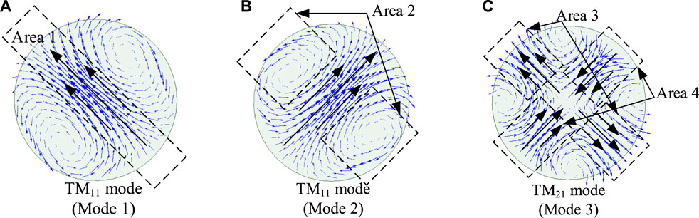
FIGURE 3. Simulated H-fields of the resonant modes in the circular patch. (A) TM11 mode (Mode 1), (B) TM11 mode (Mode 2), and (C) TM21 mode (Mode 3).
Two coupling apertures placed in the above regions are utilized for the internal coupling of both passbands in a vertically stacked form. Accordingly, the same field patterns from the TM11 mode (Mode 1) and TM21 mode (Mode 3) on the bottom-layer patch will be excited. When the feeding output ports are chosen to place at two sides of the symmetrical plane as Ports 2 and 2′, balanced outputs can be attained for both the TM11 mode (Mode 1) and the TM21 mode (Mode 3) in the bottom-layer patch.
It should be mentioned that, under CM excitation, the TM11 mode (Mode 1) and TM21 mode (Mode 3) cannot be supported on the patches, while the TM11 mode (Mode 2) can be activated. Thanks to the fields of Mode 2 that are weak around coupling apertures as shown in Figure 3, the CM signals can hardly be coupled to the bottom-layer resonator. Therefore, the CM suppression will be obtained with this structure.
Based on the above analysis, the corresponding coupling scheme is depicted for the dual-band balanced filter, as shown in Figure 4. In the scheme, 1A and 2A represent the coupled TM11 modes (Mode 1) of the top and bottom patch resonators, respectively, to form the first passband. On the contrary, 1B and 2B denote the coupled TM21 modes of the top and bottom patch resonators for the second passband. As is known, for the intact circular patch, the resonant frequency (fnm) of each mode (TMnm) is determined by the radius r of the circular patch, and the formula is provided as follows [17]:
where c is the speed of light.
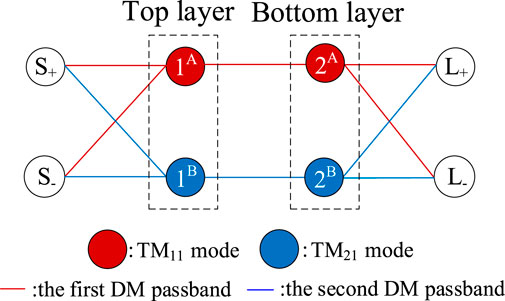
FIGURE 4. Coupling scheme for the dual-band balanced filter.
According to Eqs. 1–3, the two resonant frequencies of the interested modes for the dual-band balanced BPF are simultaneously changed with various radii r. Therefore, it is impossible to independently control two passbands by just changing the radius r. To further improve the flexibility of the design, two slot perturbations on the patch are carefully introduced in the patches as shown in Figure 1 to perturb the TM21 (Mode 3) resonant mode while seldom influencing the TM11 mode (Mode 1), according to the magnetic-field patterns in Figure 3. Therefore, the higher passband can be independently tuned, while the lower passband remains almost unchanged. In other words, two passbands can be flexibly controlled by simultaneously tuning the above slots and size of the patch. For more clear illustration, Figure 5 provides the effect of changing the length of the slot l1 on the passbands. It can be seen that the first passband stays remained, while the second passband shifts to lower frequency with an increase in slot length l1.
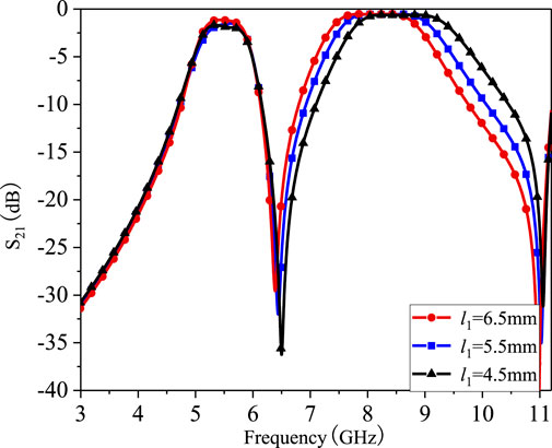
FIGURE 5. Simulated S21 of the filter against varied l1.
Herein, it is worth mentioning that, with the involvement of the introduced slot perturbations, the field distributions of the TM11 mode (Mode 2) will be affected. As such, the resonant frequency of the TM11 mode (Mode 2) under CM excitation will be shifted away from that of the TM11 mode (Mode 1) under DM excitation. For better understanding of this principle, Figure 6 gives the performance of CM suppressions with and without slot perturbations on the bottom and top patches. As can be seen, due to slot perturbations, the resonant frequency of the TM11 mode (Mode 2) is shifted from 6.0 to 4.5 GHz when compared to the design without slots. The CM suppression has been highly enhanced from 19 to 40 dB for the lower passband, while it remains above 48 dB for the second passband in both cases.
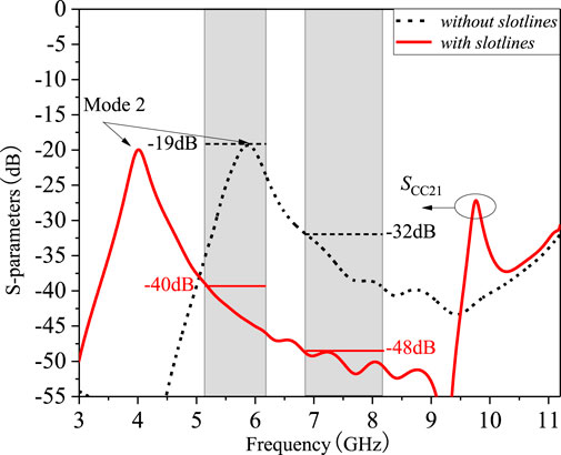
FIGURE 6. Simulated frequency responses with and without slot lines on top and bottom metal layers.
To verify this design concept, a dual-band balanced BPF that can operate at the center frequencies of f1 = 5.5 GHz and f2 = 7.5 GHz with bandwidths BW1 = 1,000 MHz and BW2 = 2,000 MHz, and in-band return loss higher than 20 dB, is designed. The corresponding design parameters are calculated as MⅠ12 = 0.037, QⅠext = 32.6 and MⅡ12 = 0.049, QⅡext = 24.4. Superscripts I and II denote the two passbands, respectively. Firstly, the initial value of the radius r is determined by the center frequency f01 of the first passband and Eqs. 1–3. Secondly, the length l1 of the slot is determined by the center frequency f02 of the second passband. Thirdly, the final parameters of the feedline (lF), slots (w1), and internal coupling apertures (w2 and l2) are optimized to achieve a compromise for calculated external quality factors (Qext) and internal coupling coefficients (Mij) of both passbands. Herein, it is worth mentioning that as the internal coupling is obtained using the same coupling apertures for both passbands, the two passband bandwidths will not be able to be independently controlled.
Measurement and Discussions
Based on the given specifications and design procedures discussed above, the size of the proposed dual-band balanced filter can be determined as follows: r = 8.0, l1 = 6.0, l2 = 4.9, lF = 5, w1 = 0.3, and w2 = 0.68 (unit: mm). A dual-band balanced filter is designed and manufactured. Simulation and measurement results are shown in Figure 7. The measured results show that the CFs are 5.5 and 7.5 GHz and the 3 dB BWs are 1.0 GHz (18%) and 2.0 GHz (26%). In the two passbands, the measured insertion loss is both less than 1.4 dB and the return loss is both higher than 22 dB. Common-mode inhibition is higher than 40 dB.
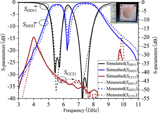
FIGURE 7. Simulated and measured results.
Table 1 compares the proposed dual-band balanced filter with other state-of-the-art designs. The present work not only exhibits a new effective design method for a dual-band balanced patch filter but also achieves nice operation performance in terms of much wider bandwidths, independently controllable center frequencies, better return loss, competitive common-mode suppression, compact size, etc.
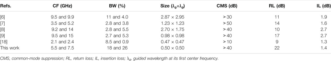
TABLE 1. Comparison with other previous works.
Conclusion
A new dual-band balanced patch filter has been designed and implemented in this letter. The resonant modes of circular patch TM11 mode and TM21 mode are explored to design the dual-band balanced filter. By wisely etching coupling apertures on the ground and introducing slots on the patch, a nice controllable dual-band response and improved CM suppression are attained in the design. Measured results coincide well with simulated ones, verifying the proposed design concept. It is our belief that this design has a prospect of broad application in the application of wireless communication systems.
Data Availability Statement
The original contributions presented in the study are included in the article/supplementary material, and further inquiries can be directed to the corresponding author.
Author Contributions
YX conducted extensive analysis and wrote this paper. ZL gave assistance in the measurement. SW and TC revised this paper. JC contributed to the funding support.
Funding
This work was supported by the National Natural Science Foundation of China (No. 61802055) and the Fundamental Research Funds for the Central Universities (No. N2019001).
Conflict of Interest
The authors declare that the research was conducted in the absence of any commercial or financial relationships that could be construed as a potential conflict of interest.
References
1. Roberto G, G, José-María M, F, Li Y, Dimitra P. Contiguous-channel Dual-Band Balanced Diplexer. IEEE Microw Wirel Compon Lett (2019) 29(5):318–20. doi:10.1109/lmwc.2019.2904396
2. Wei F, Jay Guo Y, Qin P-Y, Wei Shi X. Compact Balanced Dual- and Tri-band Bandpass Filters Based on Stub Loaded Resonators. IEEE Microw Wireless Compon Lett (2015) 25(2):76–8. doi:10.1109/lmwc.2014.2370233
3. Wu X, Wan F, Ge J. Stub-loaded Theory and its Application to Balanced Dual-Band Bandpass Filter Design. IEEE Microw Wireless Compon Lett (2016) 26(4):231–3. doi:10.1109/lmwc.2016.2537045
4. Song Y, Liu HW, Zhao W, Wen P, Wang Z. Compact Balanced Dual-Band Bandpass Filter with High Common-Mode Suppression Using Planar Via-free CRLH Resonator. IEEE Microw Wireless Compon Lett (2018) 28(11):996–8. doi:10.1109/lmwc.2018.2873240
5. Ren B, Ma Z, Liu H, Ohira M, Guan X, Wen P. Design of Balanced Dual-Band Superconducting Bandpass Filter with High Selectivity and Deep Common-Mode Suppression. Pro Asia-pacific Micro Confer (2018) 423–5. doi:10.23919/apmc.2018.8617383
6. Xu X, Wang J, Zhang G, Chen J. Design of Balanced Dual‐band Bandpass Filter Based on Substrate Integrated Waveguide. Electron Lett (2013) 49(20):1278–80. doi:10.1049/el.2013.2371
7. Li P, Chu H, Zhao D, Chen RS. Compact Dual-Band Balanced SIW Bandpass Filter with Improved Common-Mode Suppression. IEEE Microw Wireless Compon Lett (2017) 27(4):347–9. doi:10.1109/lmwc.2017.2678428
8. Shen Y, Wang H, Kang W, Wu W. Dual-band SIW Differential Bandpass Filter with Improved Common-Mode Suppression. IEEE Microw Wireless Compon Lett (2015) 25(2):100–2. doi:10.1109/lmwc.2014.2382683
9. Zhou K, Kang W, Wu W. Compact Dual‐band Balanced Bandpass Filter Based on Double‐layer SIW Structure. Electron Lett (2016) 52(18):1537–9. doi:10.1049/el.2016.1968
10. Chen J-X, Zhan Y, Qin W, Bao Z-H, Xue Q. Novel Narrow-Band Balanced Bandpass Filter Using Rectangular Dielectric Resonator. IEEE Microw Wireless Compon Lett (2015) 25(5):289–91. doi:10.1109/lmwc.2015.2409805
11. Janković N, Bengin V, C. Balanced Bandpass Filter Based on Square Patch Resonators. Pro. 12th Int. Conf. Telecom. Mod. Satell., Cable Broadcast. Services (TELSIKS); 14-17 Oct. 2015; Nis, Serbia,IEEE (2015) 14–7. doi:10.1109/telsks.2015.7357766
12. Liu Q, Wang J, Zhu L, Zhang G, Wu W. Design of a New Balanced-To-Balanced Filtering Power Divider Based on Square Patch Resonator. IEEE Trans Microwave Theor Techn. (2018) 66(12):5280–9. doi:10.1109/tmtt.2018.2871180
13. Zheng S, Wu R, Liu Z. A Balanced Bandpass Filter with Two Transmission Zeros Based on Square Patch Resonators. Proc. IEEE Int. Conf. Ubiquitous Wireless Broadband (ICUWB); 16-19 Oct. 2016; Nanjing, China, IEEE (2016) 1–3. doi:10.1109/icuwb.2016.7790443
14. Liu Q, Wang J, Zhang G, Zhu L, Wu W. A New Design Approach for Balanced Bandpass Filters on Right-Angled Isosceles Triangular Patch Resonator. IEEE Microw Wireless Compon Lett (2019) 29(1):5–7. doi:10.1109/lmwc.2018.2884829
15. Liu Q, Wang J, He Y. Compact Balanced Bandpass Filter Using Isosceles Right Triangular Patch Resonator. Electron Lett (2017) 53(4):253–4. doi:10.1049/el.2016.2715
16. Wu RT, Zheng SY, Feng WJ, Li YX, Long YL. Design of Balanced Filtering Components Based on Isosceles Right-Angled Triangular Patch. IEEE Trans Compon., Packag Manufact Technol (2019) 9(4):736–44. doi:10.1109/tcpmt.2018.2872588
17. Chakravarty T, De A. Design of Tunable Modes and Dual-Band Circular Patch Antenna Using Shorting Posts. IEE Proc Microw Antennas Propag (1999) 146(3):224–8. doi:10.1049/ip-map:19990629
Keywords: dual-band, balanced, filter, multilayer, circular patch
Citation: Xu Y, Liu Z, Wang S, Tang W and Chen J (2021) Design of a Multilayer Dual-Band Balanced Bandpass Filter on a Circular Patch Resonator. Front. Phys. 9:709150. doi: 10.3389/fphy.2021.709150
Received: 14 May 2021; Accepted: 07 June 2021;
Published: 25 June 2021.
Edited by:
He Zhu, University of Technology Sydney, AustraliaReviewed by:
Xujun Yang, Shenzhen University, ChinaLiu Qianwen, Nanjing University of Posts and Telecommunications, China
Copyright © 2021 Xu, Liu, Wang, Tang and Chen. This is an open-access article distributed under the terms of the Creative Commons Attribution License (CC BY). The use, distribution or reproduction in other forums is permitted, provided the original author(s) and the copyright owner(s) are credited and that the original publication in this journal is cited, in accordance with accepted academic practice. No use, distribution or reproduction is permitted which does not comply with these terms.
*Correspondence: Shiyan Wang, nustwang@163.com