
Abstract
The effect of superimposed ultrasonic vibration on the primary creep of metals is modeled in terms of the synthetic theory of irrecoverable deformation. We consider two sonication modes: (i) the ultrasound acts continuously during the deformation, and (ii) the ultrasound is periodically on and off. Whereas both cases show a significant increase in primary creep, the periodical sonication leads to higher deformation values. To catch the phenomenon of ultrasound-assisted creep, we extend the flow rule equation by a term that accounts for the process occurring on the microlevel of material induced by ultrasound.
1 Introduction
In recent years, ultrasonic vibration has been widely applied to assist conventional metal forming processes, such as wire drawing, extrusion, deep drawing, bending, and forging.
Due to the significance of metal forming processes in automotive, avionic, and biomedical industries, rigorous efforts were made to improve these forming processes. Many techniques were developed for this purpose. Two traditional techniques to improve the forming process are the use of lubricants and preheating the material. The major benefits of using lubricants are reducing forging load, tools’ wear, and improved surface finish (surface effect). The main limitation in using lubricants is the incompatibility with the environment and its chemical reaction with tool/workpiece material. With the preheating method, the material’s ductility increases, whereas yield strength decreases (volume effect), but it affects crucial material properties such as surface structure, crystallographic structure, and material strength. During heating, there are voids, composition, and inclusion or precipitation formation (Khan et al. 2013). Application of vibration is the most recent and beneficial technique to improve the forming processes because it offers both surface and volume effects. Vibration influences the movement of dislocation, producing plasticity, which is the main aim of the forming processes. Moreover, it can prevent the undesirable effects related to two preceding techniques.
Ultrasonic technology is also widely used in the biomedical field for diagnostic imaging and medical research.
From the middle of the 20th century onwards, the effect of ultrasound on metals’ plastic and creep deformation catalyzes an enormous interest among researchers. The first studies of the plastic and creep deformation coupled with acoustic energy are associated with the works of Blaha and Langenecker (1955), Severdenko and Klubovich (1961), Neville and Brotzen (1957), Tsimbalistyj and Vlasenko (1983), and Siegel (1959). Although many experimental and theoretical studies have been conducted since then, the researchers are far from fully understanding all the mechanisms related to ultrasound-assisted deformation.
Consider strain-time diagrams for copper at \(20\ {}^{\circ}\mbox{C} \) in uniaxial tension, \(\sigma =30\ \mbox{MPa}\), obtained by Kulemin (1978). Curve 1 in Fig. 1 is an ordinary creep diagram under the action of the static stress alone. Since the experiments were conducted at room temperature, the steady-state creep rate tends to zero. Curve 2 demonstrates the development of deformation with time under the simultaneous action of the static and oscillating load (oscillating stress amplitude \(\sigma _{m} =2.6\ \mbox{MPa}\)). It is easy to see that the acoustic energy induces a significant increase of the primary creep deformation compared to the ordinary creep. At the same time, there is no change in the secondary creep rate, which can be attributed to the low experiment temperature. According to Kulemin’s experiments conducted at higher temperatures, the ultrasound increases the secondary creep rate as well. Another distinctive feature of ultrasound-assisted creep is an increase in the duration of its primary portion (\(\approx 60\ \min \) against 20 min for the ordinary creep). Finally, Curve 3 was obtained when the ultrasound with \(\sigma _{m} =2.6\ \mbox{MPa}\) is switched on periodically for 20-minute periods: [20–40], [60–80], and [100–120]. We can see that each time the ultrasound is on, the deformation begins to grow, but the values of deformation increments decay with the number of the ultrasound switches, and there comes the point when the ultrasound exerts no effect. Remarkably, the primary creep lasts for 60 seconds for continuous ultrasound and terminates at the end of the third 20-minute portion of the sonication. Another interesting result is that the total effect from the periodic action of ultrasound (\(3\times 20\) min) is greater than that when ultrasound acts continuously for 60 min.

Strain vs. Time curves of copper for ordinary (1) and ultrasound-assisted loading (2,3) (Kulemin 1978). The creep diagrams are shown only (without the initial plastic deformation)
In addition, we study aluminum’s primary creep in the acoustic field. Kulemin (1978) reports an increase in creep deformation due to the action of ultrasound, similarly to the case considered above.
To interpret/explain the results of the experiments, we utilize the dislocation mechanism of irrecoverable deformation. As well known, creep deformation develops mainly via dislocation climbs initiated by vacancy flows. The primary creep’s driving force is energy stored in the material during active loading before the creep.Footnote 1 When this energy is exhausted, the material undergoes the transition into a steady-state creep.
With ultrasound, researchers report the following mechanisms of ultrasonic energy:
-
(i)
A stress superimposition mechanism proposed by Malygin (2000) implies that ultrasonic waves activate anchored dislocations, hardened under ordinary deformation, and decrease stresses for further inelastic deformation. However, according to Daud et al. (2007), we should avoid the simple addition of unidirectional and oscillatory stresses. For example, consider Fig. 2, where the creep rate of aluminum at \(\sigma =10\ \mbox{MPa}\) and \(T=40\ {}^{\circ}\mbox{C} \) is shown as a function of additional static stress \(\Delta \sigma \) (1) and ultrasonic stress amplitude (2). It is easy to see that, for example, the creep rate in the ultrasonic field with \(\sigma _{m} =2.0\ \mbox{MPa}\) is about five times greater than that under the action of static stress \(\sigma +\Delta \sigma \), where \(\Delta \sigma = \sigma _{m} =2.0\ \mbox{MPa}\).
Fig. 2 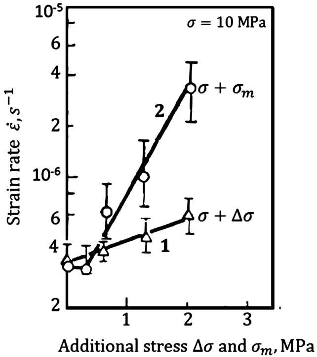
Dependence of the strain rate of aluminum on the additional static loading (1) and the additional ultrasound stress amplitude (2) (Kulemin 1978)
-
(ii)
Deshpande et al. (2019) draw an analogy between the effects of hot deformation and ultrasound action. They indicate that when thermal energy is replaced with ultrasonic energy, similar microstructure evolution can be observed. As a result, numerous investigators (e.g., Lum et al. (2009), Huang et al. (2009)) suggest that ultrasonic vibration induces sufficient heat input to the sample to produce some softening of microstructure.
-
(iii)
Kulemin (1978) investigated the effect of ultrasound on creep in copper and germanium. The increase in creep rate was supposed to be attributable to the nucleation of point defects.

Based on the foregoing, we explain the increase of primary creep in the acoustic field by the combined action of the factors listed above: (i) acoustic energy causes motion of blocked and hindered dislocations via the inflow of ultrasound-nucleated vacancies, (ii) sonication increases deformation within active slip systems and involve new ones, and (iii) ultrasound softens the material, similarly to heat energy. Injecting acoustic energy into material that already possesses some deformation energy, we observe an even more significant effect (Curve 3 in Fig. 1). Yao et al. (2012) reported a similar situation when studying ultrasonic softening during plastic deforming.
The increase in the number of defects involved in ultrasound-assisted creep necessarily entails the growth of time needed to transmit the material structure into an equilibrium state inherent to the steady-state creep (about 20 min for the ordinary creep and above 60 min for the ultrasound-assisted creep, Fig. 1).
Our paper is aimed to model the effect of ultrasound upon the primary creep of metals. For mathematical apparatus, we utilize the synthetic theory of irrecoverable deformation (Rusinko and Rusinko 2011), which has already shown satisfactory results in the analytical description of many problems related to ultrasound effects (Rusinko 2011, 2014).
2 Mathematical model. The synthetic theory of irrecoverable deformation (ST)
The synthetic theory incorporates the Budiansky slip concept (1949) and the Sanders flow theory (1954).
ST models an irrecoverable deformation on two material structure levels, micro- and macrolevel, similarly to the slip concept. Plastic or creep deformation at a point of a body (macrolevel) is determined via strain vector components (\(e_{k}\)) in the Illyushin three-dimensional strain deviator subspace (\(\mathcal{S}^{3}\)):
where \(\varphi _{N}\) is the irrecoverable strain intensity. The strain intensity is a scalar magnitude that expresses an average measure of plastic slip on the microlevel of material structure, that is, within one slip system. The orientation of slip systems is determined via \(N_{k}\), and \(dV\) reflects an elementary set of slip systems involved in plastic flow due to an infinitesimal increase in load. As can be seen from (1), we calculate the macrodeformation as a sum of the microdeformations occurring within all active sip systems. Taking into account the well-known fact that crystalline lattice defects (dislocations, vacancies, etc.) are the carriers of plastic/creep deformation, ST works with the following relationships:
where \(\psi _{N}\) is the defect intensity, an average measure of defects generated in the course of irrecoverable deforming. In the formula, \(r\) is the model constant regulating the strain hardening of material (Rusinko and Rusinko 2011). Formula (2) says that the change in the number of defects depends on two concurrent processes, the growth of deformation (\(r d\varphi _{N}\)) and the time-dependent relaxation/recovery of defects (\(- K \psi _{N} dt\)). Equation (2) enables us by a unique relationship to model both plastic and creep deformation. Generally, we use the notion of irrecoverable deformation, which, depending on the concrete loading regime, can manifest itself either in the form of plastic (instant) or creep (time-dependent) deformation.
Index \(N\) in \(\varphi _{N}\) and \(\psi _{N}\) stands to reflect the indisputable fact that the amount of deformation (\(\varphi _{N}\)) and the number of defects involved (\(\psi _{N}\)) strongly depend on the orientation of the slip system relative to the acting stresses. To catch it, we utilize Sanders’s approach. ST does not deal with a yield/loading surface itself: for the initial state, we take the von Mises criterion, but with its tangent planes, that is, the yield surface is considered an inner envelope of the tangent planes. The location of a plane is defined by its distance \(H_{N}\) from the origin of coordinates and normal unit vector with components \(N_{k}\).
A stress vector \(\overrightarrow{\boldsymbol{S}}\) in \(\mathcal{S}^{3}\) expresses a load in terms of ST. Its components are composed so that the stress vector’s length is proportional to the stress deviator tensor’s second invariant. During loading, the stress vector shifts on its endpoint a set of planes from their initial position. The movements of the planes located on the endpoint of the vector \(\overrightarrow{\boldsymbol{S}}\) are translational. The planes that are not on the endpoint of the vector \(\overrightarrow{\boldsymbol{S}}\) remain unmovable. The displacement of a plane on the endpoint of the stress vector represents a plastic flow within the corresponding slip system.
The following relationship defines the defect intensity:
where \(I_{N}\) is the rate integral, and \(S_{P}\) is the radius of the initial von Mises sphere, \(S_{P} = \sqrt{{2} / {3}} \sigma _{P}\), and \(\sigma _{P}\) is the creep strength of a material. The scalar product \(\overrightarrow{\boldsymbol{S}} \boldsymbol{\cdot } \overrightarrow{\boldsymbol{N}}\) defines the resolved shear stress acting in one slip system.
The rate integral
reflects the effect of loading rate upon the development of deformation. It increases during an active loading and decreases as the stress becomes constant in time (primary creep). The condition \(I_{N} \rightarrow 0\) symbolizes that the creep deformation increases in a linear manner (secondary creep).
In formula (2), a function \(K\) of temperature and acting stress governs the secondary creep. Indeed, as \(d \overrightarrow{\boldsymbol{S}}\) and \(I_{N}\) equal zero, Eqs. (2) and (3) give that \(d\psi _{N} =0\) and
Since, according to Fig. 1, there is no deformation increment in the secondary creep portion due to the low temperature, we conclude that \(K=0\), and Eqs. (2) and (3) lead to the relationship
The rate integral for the active loading and constant stress, respectively, is (Rusinko and Rusinko 2011)
where \(0< B<1\), \(p\) are model constants, and \(B\) and \(p\) regulate the magnitude and duration of primary creep, respectively.
3 Extension of the synthetic theory to the case of ultrasound-assisted creep
With the purpose of the extension of the synthetic theory for creep in the ultrasonic field, there are two ways to manipulate formula (6): (i) to modify the rate integral or (ii) to insert a new term into (6). The first proposition is not promising because, according to the experiment from Fig. 1, the periodic sonication starts at the end of the primary creep portion, \(I_{N} \rightarrow 0\), and there is no effect from the rate integral. Besides, when the ultrasound is off, the creep develops with the same velocity as during ordinary loading. If so, then we introduce a new term \(U_{C}\), which reflects the creep properties of a material in the ultrasonic field:
We define \(U_{C}\) as
where \(\psi _{\mathit{NU}}\) is ultrasound-induced defects intensity proposed by Rusinko in its early work (2011):
In this formula, \(S_{m}\) is the oscillating stress amplitude, and \(\overrightarrow{\boldsymbol{u}}\) is a unit vector indicating the vibration mode (longitudinal, torsional, etc.). For longitudinal sonication, the vector \(\overrightarrow{\boldsymbol{u}}\) has the coordinates \(\left ( 1,0,0 \right )\) in \(\mathcal{S}^{3}\), \(A_{1}\), \(A_{2}\), and \(w\) are the model constants to be chosen to fit the theoretical results to experimental ones. The scalar product in (10) means that the ultrasound effect strongly depends on the slip system orientation.
The term \(U_{C}\) in (9) symbolizes the increase of plastic slip within one slip system (ultrasonic softening) caused by the nucleation and development of ultrasound-induced defects. To avoid misunderstanding that the increasing number of defects would harden the material, we address Kulemin’s (1978) explanation: “When external loading couples with ultrasonic irradiation, both hardening and softening occur. The softening, however, is more intensive, and we observe the phenomenon of temporary softening.” Therefore Eq. (9) is dual; on the one hand, the ultrasound defects harden the material, but, on the other hand, they become centers of softening processes.
We substantiate the composition of \(\psi _{\mathit{NU}}\) as follows. The power function \(A_{1} S_{m}^{A_{2}}\) in (9) reflects numerous studies carried out on zinc, cadmium, aluminum, copper, and steel Bagherzadeh and Abrinia (2015), Geibler et al. (2009), Huang et al. (2009), Lum et al. (2009), Yao et al. (2012), Zhou et al. (2018), and Kulemin (1978). They report that the number of ultrasound-induced defects, and therefore the magnitude of ultrasonic softening depends on the ultrasonic stress amplitude. Further, the function \(\left ( 1- e^{-wt} \right )\) governs the evolution of the softening effect with time. As \(e^{-wt}\) tends to zero, \(\psi _{\mathit{NU}}\) stabilizes at a constant value, reflecting the well-known fact that the number of ultrasound defects first increases with time and then reaches a plateau (Tyapunina et al. 1982; Kulemin 1978). Now it is clear why each successive switch of ultrasound (see Fig. 1) results in smaller deformation increments; this is due to the exhaustive character of ultrasound-induced defects.
To reflect the fact that the effect of sonication depends on the material’s deformation state, we propose to write down \(A_{1}\) from (9) as a linear function of deformation:
4 Uniaxial tension and longitudinal sonication
4.1 Unidirectional loading
In uniaxial tension the stress vector components are
where \(\sigma \) is the unidirectional stress tensor component.
Further, taking into account that \(N_{1} = \sin \beta \cos \lambda \) (Rusinko and Rusinko 2011), together with (8) and (13), we obtain the formula for \(\varphi _{N}\) from (6):
where \(t\) is the creep time. The range of nonzero values of \(\varphi _{N}\) is
where
Integral (1) of \(\varphi _{N}\) from (14) between limits (15), together with the conversation of the vector components into strain tensor components, gives
The function \(\Phi \) increases as its argument \(b\) decreases (Rusinko and Rusinko 2011). To follow the results shown in Fig. 1 demonstrating the creep deformations alone (without initial plastic deformation), we use the relationship
where \(b_{0}\) is calculated by (16) at \(t =0\), that is, \(a_{0} \Phi \left ( b_{0} \right )\) is the initial plastic deformation.
4.2 Simultaneous action of unidirectional loading and ultrasound
According to (9), the strain intensity in the acoustic field (\(\varphi _{\mathit{NU}}\)) is
The range of nonzero values of \(\varphi _{\mathit{NU}}\) is
where
Formulae (1) and (19)–(21) give the ultrasound-assisted inelastic deformation as
Analysis of formulae (20)–(23) shows that \(\mathcal{E}_{U} >\mathcal{E}\) due to the appearance of \(U_{C}\) in (20) and (22):
-
(i)
\(\varphi _{\mathit{NU}} > \varphi _{N}\), acoustic intensity increases deformation within active slip systems;
-
(ii)
\(b_{U} < b\), ultrasound increases the number of active slip systems where irrecoverable deformation occurs.
To obtain graphs as in Fig. 1, we use the following formula:
where \(b_{U0} = b_{U} \left ( t =0 \right )\).
Formally, the fact that both \(\Phi \left ( b_{U} \right )\) and \(\Phi \left ( b_{U0} \right )\) are greater than \(\Phi \left ( b \right )\) and \(\Phi \left ( b_{0} \right )\), respectively, does not necessarily mean the same for their differences. To simplify derivations, let us apply the approximated relationship for the function \(\Phi \) (Rusinko and Rusinko 2011):
On the base of formulae (19), (24), and (25), inspect the sign of
The result is
Since \(e^{-2pt} <1\) as \(t>0\), we can conclude from the formula above that \(\Delta >0\).
4.3 Periodic switch of ultrasound during creep deformation
Consider the following regime of sonication:
where \(\tau \) is the sonication duration, and \(T\) is the ultrasound-free period.
Now formula (24) takes the following form:
where \(b_{Ui}\) is calculated via (27) at \(t= t_{i} +\tau \), and \(b_{U0}\) corresponds to the very beginning of sonication, that is, it is taken from (16).
Now inspect the formula above for conformity with experimental data. As it follows from (10) and (11), the increment in creep deformation decreases with each subsequent sonication, since \(\left ( 1- e^{-wt} \right ) \) tends to 1 with time. Further, after the ultrasound is off, the creep deformation ceases to increase, preserving its value obtained at the end of the previous sonication. Finally, formula (12), where the ultrasound effect is related to the material’s deformation state, ensures that the creep deformation gains a greater increment at the periodic sonication than during the continuous action of ultrasound. If we ignored Eq. (12), then both creep diagrams would tend to a common value, which contradicts the experiment results. Therefore the analytical results obtained are in complete agreement with the experimental results from Fig. 1.
5 Results, discussion
This point is aimed to plot creep diagrams for copper and aluminum in the ultrasonic field obtained in the framework of the synthetic theory.
First, consider the following cases of copper’s creep coupled with ultrasound (Fig. 1):
-
(i)
ordinary creep at stress \(\sigma =30\ \mbox{MPa}\),
-
(ii)
ultrasound-assisted creep: the ultrasound of oscillating stress amplitude \(\sigma _{m} =2.6\ \mbox{MPa}\) acts continuously from the very beginning of the creep,
-
(iii)
ultrasound-assisted creep: the ultrasound of oscillating stress amplitude \(\sigma _{m} =2.6\ \mbox{MPa}\) acts periodically: \(t_{1} =20\ \min \), \(t_{2} =60\ \min \), \(t_{3} =100\ \min \), \(\tau =T=20\ \min \) (see Eq. (28)).
To plot the ordinary creep diagram, we use formulae (19) and (16). As a result, Curve 1 in Fig. 3 constructed with \(\sigma _{P} =5\ \mbox{MPa}\), \(B=1.9\times 10^{-1}\), \(p=2.1\times 10^{-3} \ \mathrm{s}^{-1}\), and \(r=1.45\times 10^{5} \ \mbox{MPa}^{2}\) shows good agreement with the experimental one.

Strain vs. Time diagrams of copper: 1 – ordinary creep, 2 – ultrasound-assisted creep with continuous sonication, 3 – ultrasound-assisted creep with periodic sonication; symbols – experiment (Kulemin 1978), lines – model. Error bars are constructed for the case of periodic sonication (\(t\geq 40\) min)
The next step is the creep diagram with the simultaneous action of unidirectional and oscillating stresses. We stress that the model constants used above remain unchangeable here as well. Formulae (24) and (22) with model constants \(A_{1}^{\prime \prime } =5.375\ \mbox{MPa}^{1- A_{2}}\), \(A_{2} =1.0\), and \(w=9.5\times 10^{-4} \ \mathrm{s}^{-1}\) lead to a good fit between the theoretical and experimental results (Curve 2 in Fig. 3).
In the last case the first portion of the sonication starts in the 20th minute of creep when the deformation is \(\varepsilon =1.24\times 10^{-4}\). Table 1 and Curve 3 from Fig. 3 demonstrate the results obtained via Eqs. (27)–(29) at \(A_{1} ' =2.75\times 10^{3}\ \mbox{MPa}^{1- A_{2}}\).
The analysis of Fig. 3 shows that the creep deformation at the beginning of sonication (shadowed areas) increases more intensively than that obtained analytically. At the same time, with the further increase in \(t\), the model results show outstanding accordance with the experimental data for both continuous and periodic sonications. Thus, for the periodic action of ultrasound, the maximum height of error bars in Fig. 3 is only -15.85% for \(t\geq 40\ \mbox{min} \).
Another case to be tested is the ultrasound-assisted creep of aluminum (continuous longitudinal sonication is considered). Together with an ordinary creep in uniaxial tension at \(\sigma =10\ \mbox{MPa}\), the creep deformation in the acoustic field was measured at the following values of vibrating stress amplitudes: \(\sigma _{m1} =1.3\ \mbox{MPa}\) and \(\sigma _{m2} =2.0\ \mbox{MPa}\) (Fig. 4; Kulemin 1978).

Strain vs. Time diagrams of aluminum in uniaxial tension (\(\sigma =10\ \mbox{MPa}\), \(t=40\ {}^{\circ}\mbox{C} \)): 1 – ordinary creep, 2 and 3 – ultrasound-assisted creep with continuous sonication, • – experiment (Kulemin 1978), lines – model
The technique of constructing strain-time diagrams is identical to that applied early. The model curves in Fig. 4 are obtained via Eqs. (22) and (23) at \(\sigma _{P} =4.8\ \mbox{MPa}\), \(B=3.1\times 10^{-1}\), \(p=2.5\times 10^{-4} \ \mathrm{s}^{-1}\), \(r=1.1\times 10^{3} \ \mbox{MPa}^{2}\), \(A_{1}^{\prime \prime } =1.8\ \mbox{MPa}^{1- A_{2}}\), \(A_{2} =2\), and \(w=6.0\times 10^{-4} \ \mathrm{s}^{-1}\). Since the ultrasound acts from the very beginning of the experiment, that is, \(\left \vert \overrightarrow{\boldsymbol{e}} \right \vert =0\) in Eq. (12), the constant \(A_{1} '\) is not used here. Again, we can see that the action of ultrasound results in the increase of creep deformation, which is in full accordance with the experiment.
Consequently, in terms of the synthetic theory framework, we have managed to model the effect of continuous and periodic action ultrasound upon copper and aluminum primary creep.
6 Conclusion
In this paper, we performed the synthetic theory of irrecoverable deformation to model copper and aluminum creep deformation in the ultrasonic field. We considered two cases: (i) the ultrasound is superimposed upon the creep deformation during the whole experiment, (ii) the ultrasound acts periodically. In both cases, the sonication results in a drastic increase in creep deformation. At the same time, the periodic action of ultrasound results in a more significant effect than for continuous sonication. To catch the phenomena of the ultrasound-assisted creep, we inserted into the flow-rule relationship a term governing the time-dependent behavior of the material in the acoustic field related to the defects of crystalline grid nucleated due to the action of ultrasound. The model results fit well the experimental one, which testifies to the correctness of steps taken.
Data Availability
The authors confirm that the data supporting the findings of this study are available within the paper.
Notes
Creep deformation can start from elastic state as well.
References
Bagherzadeh, S., Abrinia, K.: Effect of ultrasonic vibration on compression behavior and microstructural characteristics of commercially pure aluminum. J. Mater. Eng. Perform. 24(11), 4364–4376 (2015)
Batdorf, S., Budiansky, B.: Mathematical theory of plasticity based on the concept of slip. NACA, Technical note, 871 (1949)
Blaha, F., Langenecker, B.: Dehnung von Zink-Kristallen unter Ultraschalleinwirkung. Naturwissenschaften 42, 556 (1955)
Daud, Y., Lucas, M., Huang, Z.: Modeling the effects of superimposed ultrasonic vibrations on tension and compression tests of aluminum. J. Mater. Process. Technol. 186(1–3), 179–190 (2007)
Deshpande, A., Tofangchi, A., Hsu, K.: Microstructure evolution of Al6061 and copper during ultrasonic energy-assisted compression. Mater. Charact. 153, 240–250 (2019)
Geibler, U., Schneider-Ramelow, M., Reichl, H.: Hardening and softening in AlSi1 bond contacts during ultrasonic wire bonding. IEEE Trans. Compon. Packag. Technol. 32(4), 794–799 (2009)
Huang, H., Pequegnat, A., Chang, B.H., Mayer, M., Du, D., Zhou, Y.: Influence of superimposed ultrasound on deformability of Cu. J. Appl. Phys. 106(11), 113514 (2009)
Khan, A., Nguyen, T.H., Giraud-Audine, C., Abba, G., Bigot, R., Lemaire-Semail, B.: Progressive wave: a new multisource vibration technique to assist forming processes-kinematic study, simulation results and design proposition. In: Congrés Français de Mécanique, Bordeaux, Aug 2013, France (2013)
Kulemin, A.V.: Ultrasound and Diffusion in Metals. Metallurgia Publ., Moscow (1978)
Lum, I., Huang, H., Chang, B.H., Mayer, M., Du, D., Zhou, Y.: Effects of superimposed ultrasound on the deformation of gold. J. Appl. Phys. 105(2), 024905 (2009)
Malygin, G.A.: Acoustoplastic effect and the stress superimposition mechanism. Phys. Solid State 42(1), 72–78 (2000)
Neville, G.E. Jr., Brotzen, F.R.: Effect of vibrations on the yield strength of low-carbon steel, First Technical Report, AF Contract No. AF-49-(638)-78, April 15, 1957, 11 pp.
Rusinko, A.: Analytical description of ultrasonic hardening and softening. Ultrasonics 51, 709–714 (2011)
Rusinko, A.: Influence of preliminary ultrasonic treatment upon the steady-state creep of metals of different stacking fault energies. Ultrasonics 54, 90–98 (2014)
Rusinko, A., Rusinko, K.: Plasticity and Creep of Metals. Springer, Berlin (2011)
Sanders, J.: Plastic stress-strain relations based on linear loading functions. In: Proc. 2nd US Nat. Congr. Appl. Mech., pp. 455–460 (1954)
Severdenko, V.P., Klubovich, V.V.: Deformation of metal in an ultrasonic field. Dokl. Akad. Nauk 1, 15 (1961). (Edited machine translation, USAF Foreign Technology Division)
Siegel, R.: The effect of ultrasonics on the creep of copper springs (Der Einfluss von Ultraschall auf das Kriechen von Kupperfedern). Ann. Phys. 5, 107–112 (1959)
Tsimbalistyj, Y.I., Vlasenko, V.I.: Studies of stress and creep relaxation under ultrasonic cyclic loading. In: Ultrasonics International 83 Conference Proceedings, pp. 507–512 (1983)
Tyapunina, N.A., Blagoveshchenskii, V.V., Zinenkova, G.M., Ivashkin, Y.A.: Characteristics of plastic deformation under the action of ultrasound. Sov. Phys. J. 25(6), 569–578 (1982)
Yao, Z., Kim, G.Y., Wang, Z., Faidley, L., Zou, Q., Mei, D., Chen, Z.: Acoustic softening and residual hardening in aluminum: modeling and experiments. Int. J. Plast. 39, 75–87 (2012)
Zhou, H., Cui, H., Qin, Q.H.: Influence of ultrasonic vibration on the plasticity of metals during compression process. J. Mater. Process. Technol. 251, 146–159 (2018)
Funding
Open access funding provided by Óbuda University.
Author information
Authors and Affiliations
Corresponding author
Additional information
Publisher’s Note
Springer Nature remains neutral with regard to jurisdictional claims in published maps and institutional affiliations.
Rights and permissions
Open Access This article is licensed under a Creative Commons Attribution 4.0 International License, which permits use, sharing, adaptation, distribution and reproduction in any medium or format, as long as you give appropriate credit to the original author(s) and the source, provide a link to the Creative Commons licence, and indicate if changes were made. The images or other third party material in this article are included in the article’s Creative Commons licence, unless indicated otherwise in a credit line to the material. If material is not included in the article’s Creative Commons licence and your intended use is not permitted by statutory regulation or exceeds the permitted use, you will need to obtain permission directly from the copyright holder. To view a copy of this licence, visit http://creativecommons.org/licenses/by/4.0/.
About this article

Cite this article
Rusinko, A., Alhilfi, A.H. & Rusinko, M. An analytic description of the creep deformation of metals in the ultrasonic field. Mech Time-Depend Mater 26, 649–661 (2022). https://doi.org/10.1007/s11043-021-09505-0
Received:
Accepted:
Published:
Issue Date:
DOI: https://doi.org/10.1007/s11043-021-09505-0