High-Speed Digital Detector for the Internet of Things Assisted by Signal’s Intensity Quantification
 Yidi Zhang
 Haibo Wang
- National Mobile Communications Research Laboratory, Southeast University, Nanjing, China
This paper proposes a high-speed digital detector for the Internet of Things (IoT) assisted by signal’s intensity quantification. The detector quantifies the amplitude of each pixel of the detected image and converts it into a digital signal, which can be directly applied to the IoT with wireless communication system. Two types of amplitude quantization algorithms, uniform quantization and non-uniform quantization, are applied to the detector, which further improves the quality of the detected image and the robustness of the image signal in a noisy environment. Related simulations have been established to verify the accuracy of the models and algorithms.
1 Introduction
With the development of the Internet of things (IoT) and the substantial increase in wireless communication rates, the demand for the data transmission rate of the detector is also increasing. In the IoT scenario, the detector is placed on the object to collect its information and communicate with the base station in real time [1–3]. This requires the data processing and transmission speed of the detector to meet the requirements of the communication system. This work is oriented to the radiation detector with image detection and transmission, whose requirements for image resolution are very high. For example, for the infrared image collected by the near-infrared radiation detector, if the grayscale of an individual point is changed during the transmission process, it will directly affect the base station’s judgment of the environment.
The traditional detector directly transmits the analog signal to the terminal, which means that the intensity of the received radiation signal is directly output. However, analog signals are not suitable for high-speed transmission for communication systems. At present, the existing high-speed communication systems sample and collect analog signals, convert them into digital signals, and then transmit them in the form of data streams. In addition, the analog signal is easily distorted by environmental noise during transmission, since it does not have any error correction mechanism. If future IoT systems need to incorporate detectors into wireless communication systems, digital detectors will become a necessary direction. In [4]; a multipurpose digital detector readout for medical imaging applications is presented. The readout is capable of measuring both current and charge, allowing a single detector array to perform imaging functions previously accomplished with two separate machines. [5] presents a design of a phase-sensitive detector based on matched filter principles and the signal-to-noise ratio (SNR) of the system can be up to 60 dB. The application of digital detectors greatly improves the data transmission rate and image quality of the detector [4, 6].
This paper presents a high-speed digital radiation detector assisted by high-precision signal intensity quantification. Since the detector transmits image signals, the data stream corresponds to the radiation intensity of each pixel. According to the range of radiation intensity, we quantify and classify the signal. Moreover, due to the presence of various noise in the wireless channel of the IoT, when quantizing and grading, we must consider how to remove the noise through quantization and grading if the signal is distorted by noise interference [7, 8]. Thus the high-speed digital transmission can be carried out and the quality of the transmitted image can not be affected by the environmental noise. In [9]; the quantization process in transform-based image compression has been emphasized. The proposed algorithm compress the image effectively without harming the quality of the compressed image. [10] shows that the non-uniform quantized polar decoder is capable to perform performance close to floating point performance.
The contributions of this work are as follows:
1) This article proposes a high-speed digital detector for the IoT assisted by signal’s intensity quantification. Compared with traditional radiation detectors, its detection data transmission and processing speed is faster, and it is more suitable for large-scale wireless communication networks in IoT. In addition, the detector also has the ability of adaptive error correction to environmental noise, which can ensure that the data received will not be distorted.
2) In this paper, Lloyd-Max Quantizer is used to derive the system performance under the two amplitude quantization methods of uniform quantization and non-uniform quantization. The system’s bit error rate and error variance are modeled and simulated. Simulation results prove that the detector’s quantization processing of analog signals can effectively reduce the bit error rate, thus improving the robustness of the system under channels with noise.
The rest of this paper is organized as follows. In Section 2, we propose the model of the system. The structure of the quantizer in the digital detector is analyzed. In Section 3, two types of quantization algorithms have been proposed to improve the quality of the detection signal and supplement image signal distortion caused by environmental noise. In Section 4, relevant simulations are made to verify the accuracy of the model and algorithms. Section 5 draws conclusion.
2 System Model
2.1 Digital Radiation Detector With Memoryless Quantification
As shown in Figure 1, in this digital detector system, the detector transmits the detected image information to the memoryless quantizer. The quantizer divides the amplitude interval of the signal of each pixel in the image according to the signal strength and the current channel condition to obtain the digital signal. The digital signal has a certain anti-noise ability, which greatly reduces the signal processing complexity of the base station, which is equivalent to sharing the data processing pressure of the base station to each detector. Due to the continuity of the amplitude of the input signal, the sampling value is also continuous, that is, in a limited range of signal amplitude, there are infinite amplitude levels. In application, it is not necessary to transmit each sample amplitude very accurately, only the signal composed of discrete amplitudes needs to be used to approximate the original continuous signal [11, 12]. In the case where the selected discrete amplitude interval is small enough, the difference between the approximate discrete signal and the original continuous signal can be ignored.
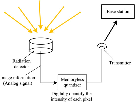
FIGURE 1. Schematic diagram of the digital radiation detector system.
Amplitude quantization refers to the process of converting the sampled amplitude of the message signal m(t) at time t = nTs into discrete amplitude v(nTs). It is assumed that the quantization process is instantaneous and memoryless, that is, the quantization value at the time t = nTs has nothing to do with the amplitude of the message signal samples before and after that time. Although the simple level quantizer has relatively weak error correction performance, it is widely used because of its low complexity and easy hardware implementation.
When discussing memoryless quantizers, the time subscript can be omitted to simplify the notation. We replace m(nTs) with m, as shown in the block diagram of the quantizer in Figure 2. In Figure 3, if the amplitude of the signal is within the separation interval, we can obtain the set of amplitudes in the separation interval ξk as
where L is the total number of quantization stages, and the signal amplitude m is determined by the subscript k, which is the decision threshold. The output terminal of the quantizer uses discrete amplitudes to represent the message amplitudes of an entire segmented interval, which is named as quantization level. The interval between two adjacent quantization levels is named as the step size.
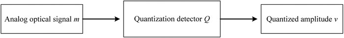
FIGURE 2. Block diagram of memoryless quantizer.

FIGURE 3. Signal quantization interval.
The quantizer can be divided into a uniform quantizer and a non-uniform quantizer according to the distribution of the step length [13–15]. In a uniform quantizer, the quantization interval is uniformly distributed, and vice versa, it is a non-uniform quantizer. Quantizers can also be divided into flat type and medium-lift type according to the distribution of characteristics. Figure 4 is the input and output curve of the medium-lift uniform quantizer, where the origin is at the midpoint of the rising part of the ladder diagram. Figure 5 shows the characteristic curve of a flat-type uniform quantizer. As the name suggests, the origin is located at the midpoint of the ladder diagram platform. Both quantizers are symmetrical about the origin.
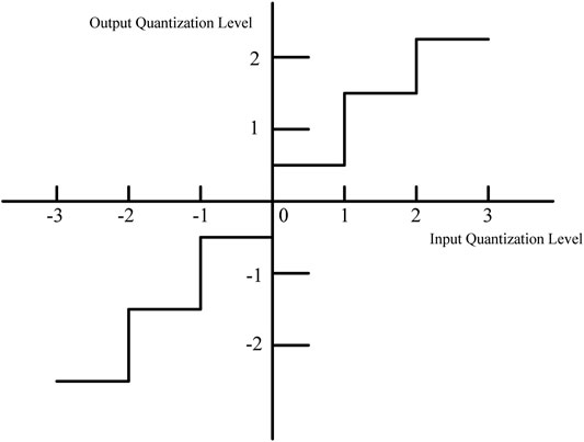
FIGURE 4. Characteristic curve of medium-lift uniform quantizer.
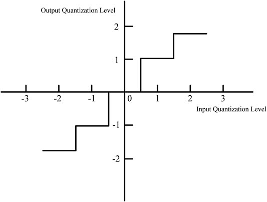
FIGURE 5. Characteristic curve of flat-type uniform quantizer.
2.2 Lloyd-Max Quantizer
When designing the quantizer, it is necessary to consider how to select the quantization level and the separation interval to make the performance optimal and the average quantization power minimum when the quantization level is fixed. Since the quantization process is a highly non-linear process, there is no complete optimization method. The Lloyd-Max quantizer ultilizes an iterative method to effectively find the optimal solution.
Assume that the dynamic range of the message signal m(t) is divided into L intervals, as shown in Figure 6. The separation interval is represented by a set of real numbers M = m1,m2,...,mL+1, defined as follows,
From (2), we can obtain the output amplitude vk when the input m falls in the interval of ξk. Define the amount of distortion d(m,vk). We can obtain the general formula for measuring distortion as
Then we look for the set of quantization levels
where fM(m) is the probability density function of the random variable M when the sampling value is m.

FIGURE 6. Schematic diagram of the signal m(t) divided into L intervals.
Since the quantization process is a highly nonlinear process, iterative algorithms are needed to optimize the design of the quantizer. From a structural point of view, the quantizer is specifically composed of two parts, the encoder represented by the set of separation intervals
Two extreme cases are defined. Case 1 is a fixed decoder, seeking the optimal encoder of the transmitter, and case 2 is a fixed encoder, seeking the optimal decoder of the receiver. In the process of designing the quantizer, the optimal encoder is always first obtained according to the case 1, and then the decoder is optimized in the case 2. The two processes are repeated alternately until the average distortion D reaches the minimum value.
3 Quantitative Algorithm
Due to the symmetry of the additive white gaussian noise (AWGN) channel, its likelihood ratio is also roughly symmetrical, which is suitable for symmetrized quantization processing. In [10]; the author proved that the function of the number of decoder iterations is related to the exponent of the message amplitude, and the range and accuracy of the quantized message in the decoder will affect the BER leveling. Therefore, we design a new quantization method with (Q + 1)-bit non-uniform quantization.
3.1 Uniform Quantization Scheme
First, we consider the Q-bit uniform quantizer. Define the boundary value of the quantizer as ±A. In the design, we use the mid-up quantizer, and the quantization step can be defined as
Assuming that the input sequence is X = x1,x2, ,xn, the quantified rule can be expressed as
Table 1 shows an example of uniform quantization when A = 1 and Q = 3.
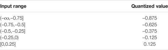
TABLE 1. Bit uniform quantization, A = 1.
3.2 Simplified Quantization Detector
Inspired by the Lloyd-Max quantizer introduced above, we propose a simplified quantitative analysis method to calculate the mean square error of different quantization schemes through the density function of the likelihood ratio discrete. Assuming that the signal sequence sent by the source is X, and the signal received by the receiving end is Y, then the transmission bits 0,1 are mapped to +1,−1 through BPSK modulation under the AWGN channel. Assuming
where σ2n is the Gaussian noise variance, which is related to the code rate and the signal-to-noise ratio. From (7), after passing through the AWGN channel, the initial information Y at the receiving end obeys the expected normal distribution, as shown in Figure 7.
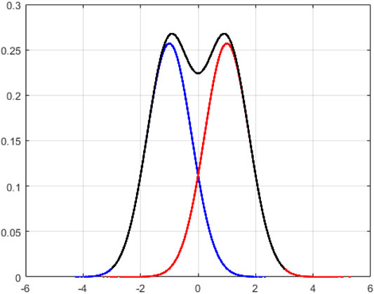
FIGURE 7. Initial information distribution (σ2n = 0.6025).
With 0 as the center, the quantization process is to decompose the continuous Gaussian curve into L intervals of quantization stages, and then divide each quantization interval into N = 8192 cells, then each interval can be approximated as a point, which has a unique corresponding probability density value. In the quantization interval, there is a certain error between the actual value and the quantized value of each point, and then we calculate the mean square error D between the actual value of the point m and the final quantized value vk as
In this way, we can obtain the mean square error of different cross-strait programs. Then, we will use a series of quantization codewords to observe whether there is a certain relationship between the quantization scheme and the quantization scheme obtained by simulation when the mean square error is minimum.
4 Numerical Results
In this section, we compare the performance obtained using the non-uniform quantization scheme with the BER performance obtained using the uniform quantization. Figure 8 shows a 2-bit uniform quantization of a Margulis rule LDPC code with a code rate of 0.5. The simulation operating point is set to the position of the BER of 10−2, and the signal-to-noise ratio at this time is 2.2 dB. The red curve in the figure is the corresponding relationship between the quantization boundary and the BER obtained under simulation. The blue curve represents the mean square error value corresponding to different boundary values. We can see that the optimal boundary of the simulated 2-bit uniform quantization is A = 1.5, and the minimum mean square error falls at A = 2.1, and the two are not consistent.
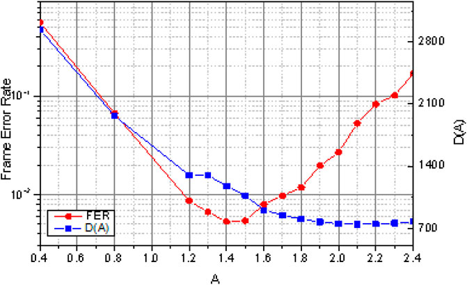
FIGURE 8. Simulation of BER and corresponding mean square error of 2-bit uniform quantization.
Figure 9 shows the non-uniform quantization of the codeword, and the operating point is set at the BER value, and the corresponding signal-to-noise ratio is 2.2 dB. We simulate different internal boundary values and different growth rate coefficients a under the same boundary value. According to the image, we get that when A1 = 0.7, η = 3, that is, A1 = 0.7, A2 = 2.1 corresponds to the lowest BER.
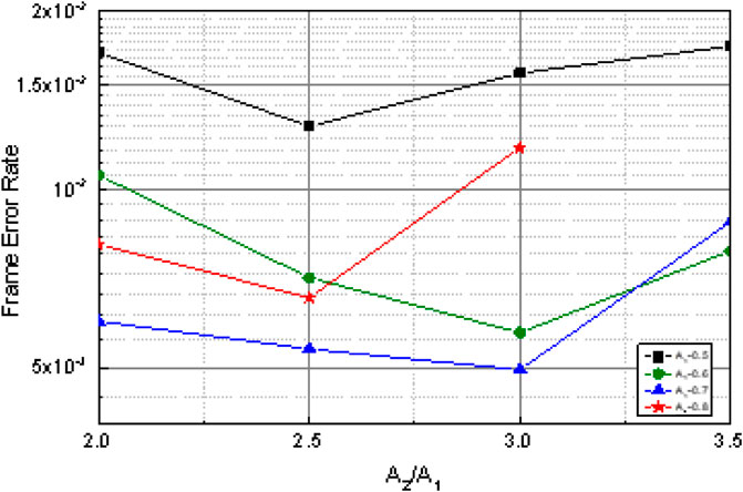
FIGURE 9. Simulation of BER of 2-bit non-uniform quantization.
Similarly, we calculate the value of the mean square error corresponding to different values, as shown in Figure 10, we observe that the lowest point of the mean square error value falls at A1 = 1, η = 2.25, that is, A1 = 1, A2 = 2.25. There is a certain difference with the non-uniform quantization scheme with the lowest BER obtained by simulation. However, compared with traditional detectors, both types of quantitative detectors have certain performance gains.
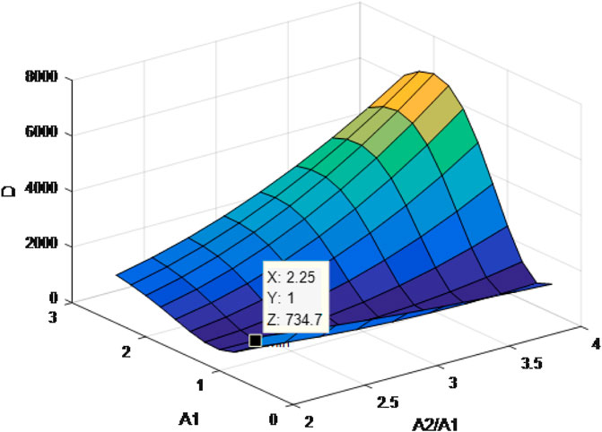
FIGURE 10. Simulation of mean square error of non-uniform quantization.
5 Conclusion
This paper proposes a high-speed digital detector for the Internet of Things (IoT) assisted by signal’s intensity quantification. The detector quantifies the amplitude of each pixel of the detected image and converts it into a digital signal, which can be directly applied to the IoT with wireless communication system. Uniform quantization and non-uniform quantization, are applied to the detector, which further improves the quality of the detected image and the robustness of the image signal in a noisy environment. Simulation results prove that the detector’s quantization processing of analog signals can effectively reduce the bit error rate, thus improving the robustness of the system under noisy channels.
Data Availability Statement
The original contributions presented in the study are included in the article/Supplementary Material, further inquiries can be directed to the corresponding author.
Author Contributions
YZ is responsible for writing the article. HW is responsible for related simulations and experiments.
Conflict of Interest
The authors declare that the research was conducted in the absence of any commercial or financial relationships that could be construed as a potential conflict of interest.
References
1. Lee C, Fumagalli A. Internet of Things Security - Multilayered Method for End to End Data Communications over Cellular Networks. In: 2019 IEEE 5th World Forum on Internet of Things (WF-IoT), ILimerick, Ireland, April,2019, (IEEE) (2019). 24–8. doi:10.1109/WF-IoT.2019.8767227
2. Alkhabbas F, Spalazzese R, Davidsson P. Architecting Emergent Configurations in the Internet of Things. In: 2017 IEEE International Conference on Software Architecture (ICSA), Gothenburg, Sweden, April, 2017, (IEEE) (2017). 221–4. doi:10.1109/ICSA.2017.37
3. Al-Fuqaha A, Guizani M, Mohammadi M, Aledhari M, Ayyash M. Internet of Things: A Survey on Enabling Technologies, Protocols, and Applications. IEEE Commun Surv Tutorials (2015) 17:2347–76. doi:10.1109/COMST.2015.2444095
4. Boles CD, Boser BE, Hasegawa BH, Heanue JA. A Multimode Digital Detector Readout for Solid-State Medical Imaging Detectors. IEEE J Solid-state Circuits (1998) 33:733–42. doi:10.1109/4.668988
5. He C, Zhang L, Liu B, Xu Z, Zhang Z. A Digital Phase-Sensitive Detector for Electrical Impedance Tomography. in: Automation Congress Proceedings, 2008 World, Waikoloa, HI, United States, (2008), 1–4.
6. Zhu X, Zhang H, Zhang Y. Design of a Digital Signal Current Detector. In: Proceedings of 2010 Chinese Control and Decision Conference, Beijing, China, July, 2010 (2010). 1713–7. doi:10.1109/CCDC.2010.5498428
7. Yang Y, Yang H, Liu F. Group Motion of Autonomous Vehicles with Anti-disturbance protection. J Netw Comput Appl (2020) 162:102661. doi:10.1016/j.jnca.2020.102661
8. Yang Y, Yang H, Liu F, Liu L. Optimal Control of Distributed Multiagent Systems with Finite‐time Group Flocking. Int J Intell Syst (2020) 35:1416–32. doi:10.1002/int.22264
9. Taujuddin NSAM, Ibrahim R, Sari S. Minimizing Median Difference Quantization Error for Image Compression. In: 2016 International Conference on Information and Communication Technology Convergence (ICTC), Shanghai, China, ( IEEE) (2016). 1160–4. doi:10.1109/ICTC.2016.7763395
10. Hasan AA, Marsland ID. Non-uniform Quantizers with Sc Polar Based Channel-Optimized Decoders. In: 2017 8th IEEE Annual Information Technology, Electronics and Mobile Communication Conference (IEMCON) (2017). p. 101–4. doi:10.1109/IEMCON.2017.8117162
11. Wang Z, Bovik AC, Sheikh HR, Simoncelli EP. Image Quality Assessment: from Error Visibility to Structural Similarity. IEEE Trans Image Process (2004) 13:600–12. doi:10.1109/TIP.2003.819861
12. Lan Y, Wang S, Shan C. A High Speed Radar Data Acquisition and Processing System. In: International Conference on Signal Processing, November, 1996, (IEEE) 1 (1996). p. 449–52. doi:10.1109/ICSIGP.1996.567299
13. Linde Y, Buzo A, Gray R. An Algorithm for Vector Quantizer Design. IEEE Trans Commun (1980) 28:84–95. doi:10.1109/TCOM.1980.1094577
14. Zhang Y, Zhu C. Quantizer Design for Correlation Noise in Distributed Video Coding. In: 2011 IEEE International Symposium on Broadband Multimedia Systems and Broadcasting (BMSB), July, 2011, (IEEE), (2011). p. 1–6. doi:10.1109/BMSB.2011.5954909
Keywords: digital radiation detector, internet of things, intensity quantification, uniform and non-uniform quantization, quantization algorithms
Citation: Zhang Y and Wang H (2021) High-Speed Digital Detector for the Internet of Things Assisted by Signal’s Intensity Quantification. Front. Phys. 9:700425. doi: 10.3389/fphy.2021.700425
Received: 26 April 2021; Accepted: 21 May 2021;
Published: 09 June 2021.
Edited by:
Gang Zhang, Nanjing Normal University, ChinaCopyright © 2021 Zhang and Wang. This is an open-access article distributed under the terms of the Creative Commons Attribution License (CC BY). The use, distribution or reproduction in other forums is permitted, provided the original author(s) and the copyright owner(s) are credited and that the original publication in this journal is cited, in accordance with accepted academic practice. No use, distribution or reproduction is permitted which does not comply with these terms.
*Correspondence: Haibo Wang, haibowang@seu.edu.cn