
Confined Plunging Liquid Jets for Dilution of Brine from Desalination Plants
by
 , , ,
, , ,
Ishita Shrivastava
1,*,† ,
,
Edward Eric Adams
2,
Bader Al-Anzi
3,
Aaron Chunghin Chow
4 and
Jongyoon Han
1 1
Department of Electrical Engineering and Computer Science, Massachusetts Institute of Technology, Cambridge, MA 02139, USA
2
Department of Civil and Environmental Engineering, Massachusetts Institute of Technology, Cambridge, MA 02139, USA
3
Department of Environmental Technologies and Management, Kuwait University, POB 5969, Safat 13060, Kuwait
4
Division of Engineering, New York University, Abu Dhabi 129188, United Arab Emirates
*
Author to whom correspondence should be addressed.
†
Currently at: Gradient, One Beacon Street, Boston, MA 02108, USA.
Processes 2021, 9(5), 856; https://doi.org/10.3390/pr9050856
Submission received: 11 April 2021
/
Revised: 5 May 2021
/
Accepted: 8 May 2021
/
Published: 13 May 2021
(This article belongs to the Special Issue Sustainable Water Treatment and Desalination with Membrane Distillation Technology)
Abstract
:Confined plunging jets are investigated as potential outfalls for the discharge of desalination brine. Compared to offshore submerged outfalls that rely on momentum to induce mixing, plunging jets released above the water surface utilize both momentum and negative buoyancy. Plunging jets also introduce air into the water column, which can reduce the possibility of hypoxic zones. In contrast to unconfined plunging jets, confined plunging jets include a confining tube, or downcomer, around the jet, which increases the penetration depth of the bubbles and can provide better aeration. However, the presence of this downcomer can hinder mixing with surrounding water. Therefore, laboratory measurements of dilution are reported here and compared to the dilution of unconfined plunging jets. In addition, qualitative observations of bubble penetration depth are also used to discuss aeration potential. For designs that increase the bubble penetration depth as compared to unconfined plunging jets, results show that dilution decreases as the depth of the downcomer is increased. However, it is shown that confined plunging jets can be designed with a short downcomer to provide higher dilution than unconfined jets. The effect of the diameter of downcomer on dilution is also investigated and a non-monotonic effect is observed.
Keywords:
plunging jet; desalination; brine; dilution; aeration; air entrainment; multiphase flow; outfall1. Introduction
Seawater desalination is a major source of freshwater for many parts of the world. In particular, countries bordering the Arabian Gulf are heavily reliant on seawater desalination for their freshwater supply, and contribute to 33% of the global desalination capacity [1]. A by-product of seawater desalination is reject brine, which is typically discharged back to the sea. Reject brine can have up to twice the salinity of seawater and, unless highly diluted, can significantly impact the marine environment. Depending on the process, brine may also contain other contaminants such as anti-fouling and anti-scaling agents, which can be harmful to benthic organisms as well [2,3,4,5].
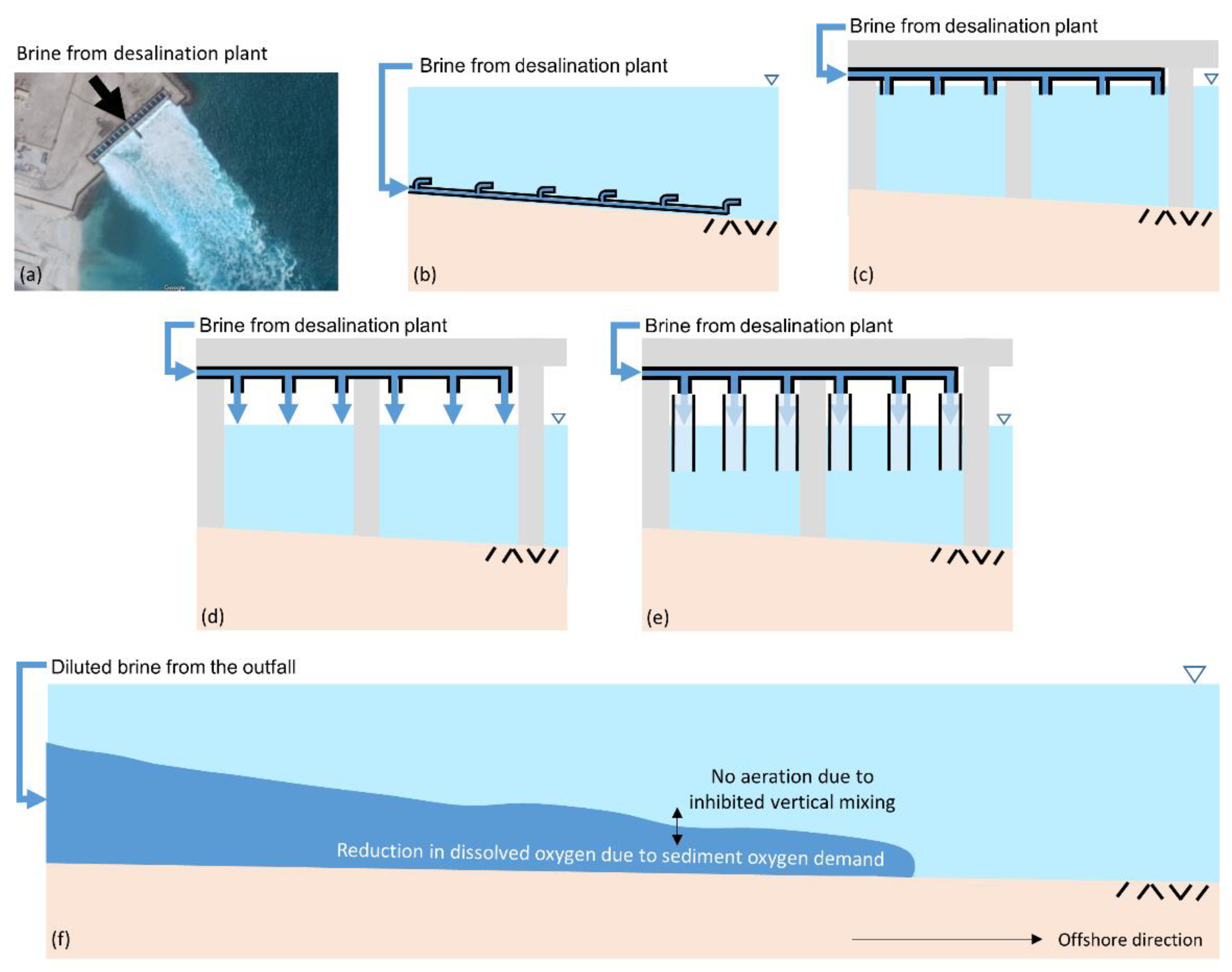
At some locations, especially those with shallow water, brine is pre-mixed with seawater or power plant cooling water and discharged using surface canals (Figure 1a), which provide limited mixing with ambient water [2]. However, to get better mixing, brine can be discharged using high momentum submerged outfalls [6,7,8,9] or buoyancy dominated surface outfalls (shown in Figure 1b,c, respectively). These outfalls result in rapid mixing of brine with ambient water in the near-field (within a few hundred meters from the discharge location), and the reduction in contaminant concentrations due to the mixing generated by these outfalls is comparable [10].
Negatively buoyant diluted brine tends to spread on the seafloor leading to density stratification, which inhibits vertical mixing between the bottom layer of diluted brine and the relatively fresh surface layer (Figure 1f). As a result, the dissolved oxygen in the bottom layer is not replenished and hypoxic or anoxic conditions can develop due to the sediment oxygen demand acting on the bottom layer [5,11,12,13]. Hypoxic conditions can strongly affect benthic organisms and have been associated with decline in fish production, fish kills and significant trophic implications [14,15,16].
In addition to the induced vertical stratification, high salinity and temperature of ambient seawater can exacerbate the problem as oxygen saturation decreases with an increase in temperature and salinity, e.g., oxygen saturation decreases from 9.1 mg/L for freshwater at 20 °C to 6.2 mg/L for seawater with salinity of 35 psu at 30 °C [17]. Development of hypoxia in bottom waters has previously been correlated with vertical stratification and warm water temperatures in estuaries [16,18,19,20], but the dense layer at the bottom can also form at other locations, e.g., offshore from a desalination plant outfall.
In order to avoid possible hypoxia as a consequence of brine discharge from desalination plants, discharge methods that actively increase aeration in the water column, in addition to providing mixing with the receiving water, should be explored. The plunging liquid jet reactor (PLJR) is one such outfall design. Plunging liquid jet reactors (Figure 1d) involve vertically downward discharge of a liquid phase (brine) from a jet that is located above the surface of the receiving water. As the jet falls through the headspace, it entrains air, which is then injected into the receiving water with the plunging jet. The downward momentum and negative buoyancy of the jet provide mixing with the receiving water and the entrained air promotes reaeration.
Plunging jet reactors have been used in the past with neutrally buoyant effluent to achieve high mass transfer from the gas phase to the liquid phase at low operating costs [21]. This is done by entraining gas bubbles into the liquid and increasing the contact time between the two phases. Plunging jet reactors are used in different processes such as gas-liquid reactors in the chemical industry, aerobic wastewater treatment, air pollution abatement, froth flotation and fermentation [22]. The oxygen transfer efficiency of plunging jets is comparable to other aeration technologies [10,23,24].
Many studies have focused on understanding the mechanisms of air entrainment and measuring the air entrainment and mass transfer associated with plunging jets discharging neutrally buoyant effluent [22,24,25,26,27,28]. However, not many have investigated the mixing capacity of plunging jets, especially for the discharge of dense effluents such as brine. Recently, mixing of plunging jets was studied by Chow et al. [10]. Dilution measured near the bottom showed a non-monotonic effect of the plunging jet height above the receiving water surface: for small heights, dilution decreased with height due to the loss of momentum caused by the splash, while for larger heights dilution increased with height due to the greater momentum due to gravity.
A variant of the plunging liquid jet reactor is the confined plunging jet reactor which includes a vertical confining tube, or downcomer, concentric with the jet and partially immersed in the receiving water (Figure 1e). Confined plunging jets have been theorized to provide better mass transfer in comparison to unconfined plunging jets by confining the bubbly jet region and increasing the penetration depth of the bubbles, which, in turn, leads to an increased contact time between the gas and the liquid phase [24,29,30,31]. However, they have not been widely investigated and experimental measurements of the air entrainment and mass transfer rate have not clearly indicated better performance in comparison to unconfined jets [24,26,29]. Two different types of air entrainment rates have been measured in these studies—the net air entrainment (amount of air that exits at the bottom of the downcomer) and the gross air entrainment (total amount of air entrained by the jet including any air that is then dis-entrained and rises to the surface within the downcomer).
Ohkawa et al. [26] made measurements of air entrainment rate for both unconfined and confined plunging jets, and found the net air entrainment rate of confined jets to be higher (by 25–60%) than unconfined jets at comparable operating conditions. For confined jets with long and narrow downcomers, they saw an increase in net air entrainment rate with increasing downcomer diameter, and decrease with increasing downcomer depth.
Low [24] made measurements of gross air entrainment rate for confined plunging jets and compared it to measurements of air entrainment for unconfined plunging jets. A significant effect of downcomer diameter on gross air entrainment rate was not observed. The empirical equations proposed by Low [24] suggested that the air entrainment rate for a confined jet is 60–75% of that for an unconfined jet.
Al-Anzi et al. [30] made measurements of net air entrainment rate for different downcomer diameters and submergence depth. They observed maximum air entrainment rate when the ratio of downcomer diameter to nozzle diameter was close to 5. They did not find a strong dependence on downcomer depth.
To the authors’ knowledge, plunging jet systems (either unconfined or confined) have not been considered as potential outfalls for brine discharge from desalination plants except in our recent work by Chow et al. [10], which looked at unconfined plunging jets. This paper aims to evaluate the mixing performance of confined plunging jets when used to discharge a negatively buoyant effluent like brine. Measurements of dilution for confined plunging jets are presented in this paper, focusing on the effects of density difference between the effluent and receiving water, and the diameter and depth of submergence of the downcomer. Dilution measurements for confined plunging jets are also compared to dilution of unconfined plunging jets under similar operating conditions. Qualitative observations of the jet behavior and bubble penetration depth are also presented.
2. Formulation
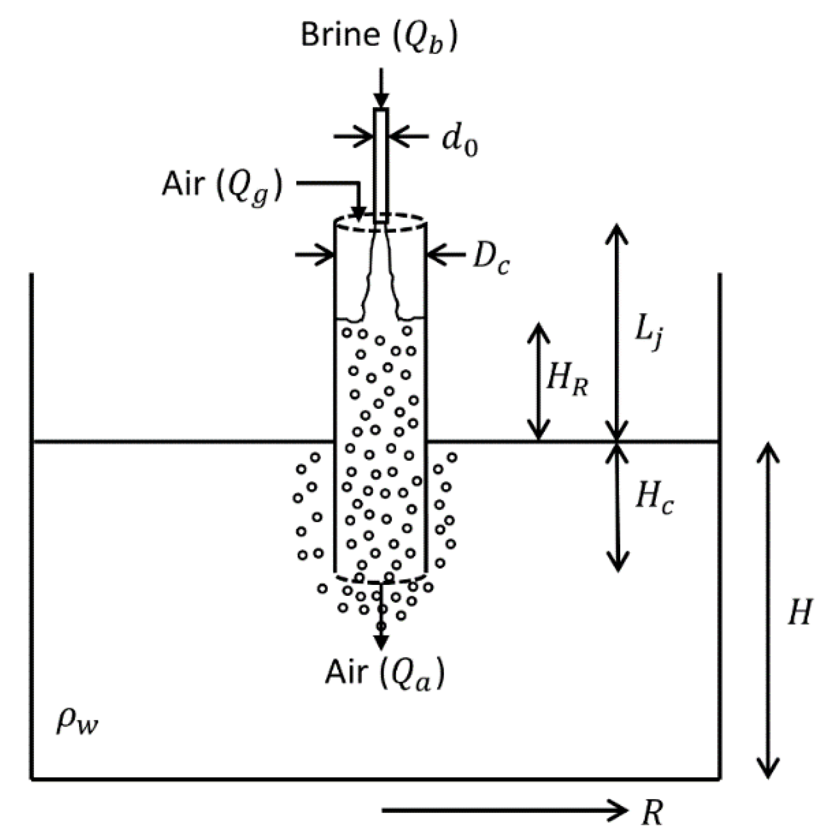
The situation analyzed in this paper is that of a confined plunging jet reactor which consists of a nozzle with diameter d0 (area a0 = (π/4)d02) discharging high salinity effluent (brine) vertically downward in quiescent receiving water with depth H. The flow rate of brine is Qb, its density is ρb (salinity difference with respect to receiving water is ∆s), and the velocity of brine exiting the nozzle is v0 = Qb/a0. The height of the jet above the water surface in the receiving pool (or the “jet length”) is Lj. A vertical confining tube (or downcomer) of diameter Dc (cross-sectional area Ac = (π/4)Dc2) is placed concentrically with the jet. The downcomer is partially submerged in the receiving water and its depth of submergence is Hc. The radial distance outward from the nozzle axis is R (Figure 2). The rise in the water level within the downcomer is denoted by HR. The flow rate of net air entrained by the jet is denoted as Qa. Gross air entrainment rate is denoted as Qg. The bubble penetration depths (the maximum depth to which bubbles propagate below the receiving water surface) for unconfined and confined jets are denoted as Hpu and Hpc, respectively.
3. Materials and Methods
Experiments to measure dilution of confined plunging jets were conducted in a tank with dimensions of 480 cm (length) × 120 cm (width) × 60 cm (depth). The tank was filled with fresh water with a depth of 50 cm for most runs and acted as the receiving water pool. Salt water (brine) was stored in a separate reservoir with a capacity of 140 L. A submersible pump was used to supply this salt water to a stainless steel nozzle, with a length of 30 cm and diameter of 1 cm, which discharged it vertically downward into the receiving pool. The distance between the nozzle and the surface of water in the receiving pool was equal to the jet length. Clear acrylic pipes of different diameters were used as the downcomer and were suspended concentric to the nozzle.
The experiments modeled one plunging jet out of an array of multiple jets discharging brine from a desalination plant. For example, consider a total brine flow rate of 1 m3/s with 6 jets (flow rate per jet = 0.167 m3/s). Using Froude scaling, and the experimental brine flow rate of 160 cm3/s, the volume ratio between the prototype and the model is Qr = (0.167 m3/s)/(160 cm3/s) = 1042, resulting in a length ratio of Lr = Qr0.4 ≈ 16. Thus, the receiving water depth of 50 cm and the nozzle diameter of 1 cm in the experiments scale to a water depth of 8 m and nozzle diameter of 0.16 m in the field. The jet length was varied between 0 and 60 cm (0 to 9.6 m in the prototype) and the salinity difference between brine and receiving water was either 40 psu or 10 psu. These values of the salinity difference represent brine from a reverse osmosis plant without any pre-dilution, and brine pre-diluted with seawater or power plant cooling water, respectively [8]. The downcomer diameter was varied between 2.5 cm and 14.6 cm with the downcomer submergence depth varied between 5 and 45 cm below the receiving water surface. Table 1 lists the experimental parameters for all the experiments.
A fluorescent dye (Rhodamine 6G) was added to the salt water discharging from the nozzle (discharge concentration = c0) and a fluorometer (Turner Designs Cyclops 7) was used to measure its concentration along the tank bottom at a radial distance of 50 cm from the nozzle. The fluorometer was calibrated with known concentrations of the fluorescent dye prior to experiments, which resulted in a linear calibration curve. The fluorescence probe measured concentration at a height of about 1.2 cm above the tank bottom. The fluorometer took measurements every second and each experiment was run for a duration of 6 min. Only the measurements taken after 3 min from the start (when the discharge of brine began) were used as the measurements appeared to be quasi-steady after 3 min for all experiments. Each experiment was also repeated (with the number of replicates = N).
The mean concentration (cmean) and the standard deviation of the mean (σmean) from these repeated runs are reported in Table 1 relative to the discharge concentration. The coefficient of variation (CV) from individual runs averaged over the repeated runs for an experiment is also reported in Table 1. For example, for run 1, the measured relative concentrations (mean ± standard deviation) are 0.080 ± 0.015, 0.084 ± 0.015 and 0.076 ± 0.013 from the 3 replicates. In this case, cmean/c0 is the average of the 3 mean values (equal to 0.080), σmean/c0 is the standard deviation of the 3 mean values (equal to 0.003), and CV is the average of 0.015/0.080, 0.015/0.084 and 0.013/0.076, equivalent to 18%.
The measured concentrations are used to calculate mean dilution (S) n the tank bottom at R = 50 cm (S = c0/cmean). The range of mean dilution is from c0/(cmean + σmean) to c0/(cmean − σmean) and is also listed in Table 1. This range is also shown in subsequent figures as “error bars.” This mean dilution reflects the average factor by which excess salinity and concentrations of other contaminants of concern present in brine are reduced.
The height of rise of water level inside the downcomer and the maximum penetration depth of bubbles were also observed visually. The height of rise of water level inside the downcomer is reported in Table 1, whereas the observations of bubble penetration depth are used qualitatively to discuss the aeration potential of confined plunging jets. In addition to experiments with confined plunging jets, some experiments were also conducted to measure dilution for unconfined jets (runs 33–38) to compare with the corresponding experiments with confined jets.
4. Results
4.1. Confined Plunging Jet Behavior
Confined plunging jets behave similarly to unconfined plunging jets which are described in detail by Chow et al. [10]. The jet entrains air as it falls through the headspace and this entrained air is injected in the water column with the jet. However, depending on the diameter and submergence depth of the downcomer, the bubbles can be transported outside the downcomer or rise within the downcomer.
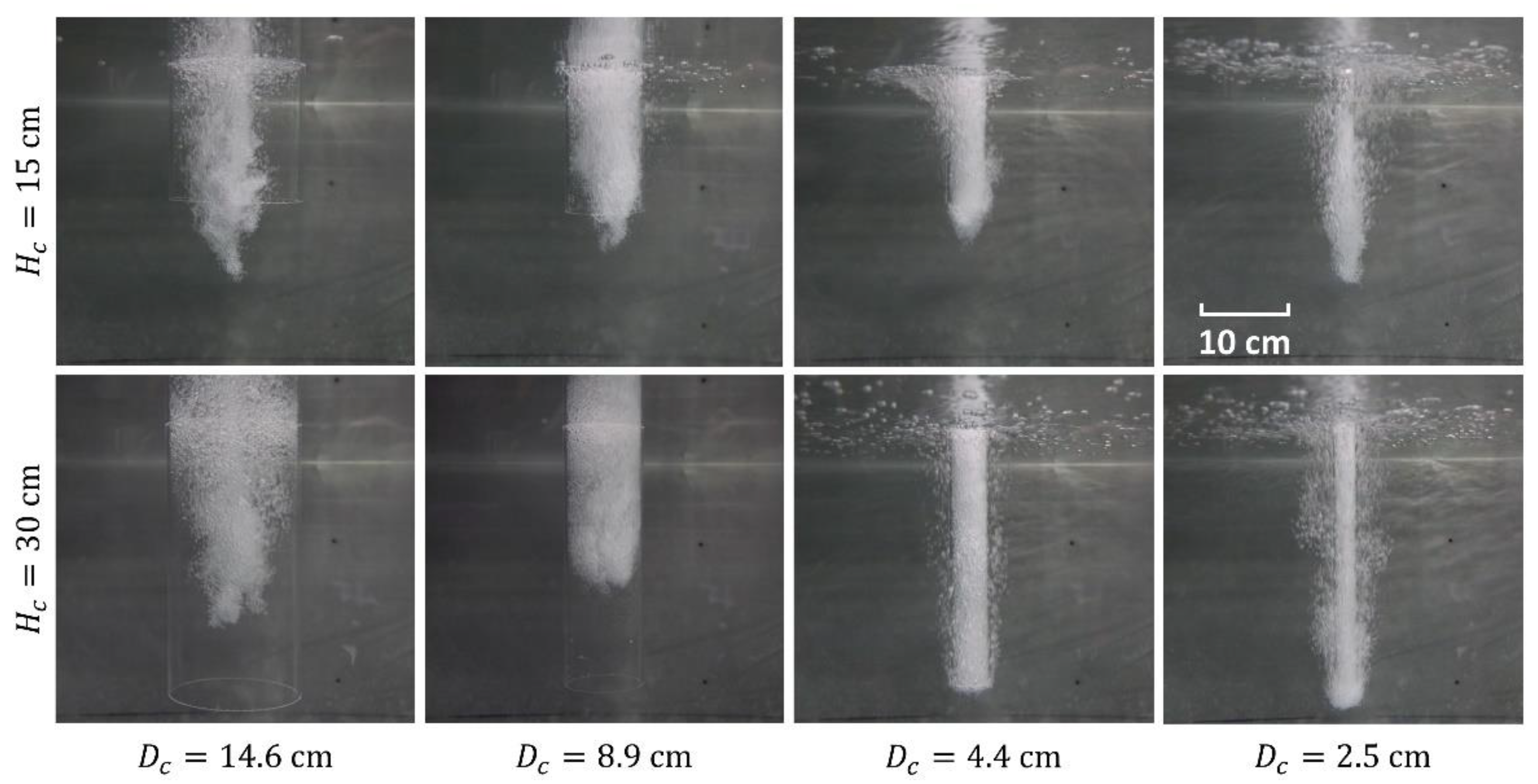
For an unconfined jet with Lj = 60 cm and ∆s = 10 psu (run 33), the bubble penetration depth was measured to be 20 cm. However, bubbles can be pushed deeper with a narrow downcomer with large Hc. For example, with the 4.4 cm wide downcomer, bubbles were seen escaping from the bottom of the downcomer and rising outside it even with Hc = 45 cm. Similarly, bubbles exited from the bottom of the downcomer for Hc = 30 cm with Dc = 2.5 cm. For the case with Dc = 4.4 cm and Hc = 45 cm, the rise in water level inside the downcomer (HR) was 29.5 cm. So, for the bubbles to be able to exit the downcomer with Hc as large as 45 cm, the downcomer needs to extend to at least 30 cm above the surface of receiving water. Otherwise, enough head cannot be generated to push the bubbles out of the downcomer.
For Hc = 15 cm, the bubbles penetrated deeper than the downcomer for all four downcomer diameters, but most of the bubbles were seen rising within the downcomer for Dc = 8.9 and 14.6 cm. Therefore, the net air entrainment for these runs is close to zero; however, aeration is expected to take place within the downcomer. For a downcomer submergence depth of 30 cm, bubbles did not reach the lower end of the downcomer for Dc = 8.9 and 14.6 cm and rose within the downcomer with a penetration depth of about 20 cm (same as that for an unconfined jet under similar conditions). Thus, runs with wide downcomers did not result in increased bubble penetration depths even with Hc > Hpu. For the two narrow downcomers, the flow within the downcomer appeared to be one-dimensional with most of the bubbles exiting the downcomer and rising outside it.
Figure 3 shows a side view of bubbles inside the downcomer for various combinations of Dc and Hc for experiments with ∆s = 10 psu. Experiments with ∆s = 40 psu looked similar to ∆s = 10 psu, except that many very fine bubbles were also observed for experiments with ∆s = 40 psu. These bubbles reached the bottom of the tank and spread radially for some distance with the diluted brine.
4.2. Dilution
To determine their effect on dilution, each variable of importance was varied independently while other variables were held constant. The effects of different variables are discussed below.
4.2.1. Effect of Downcomer Submergence Depth
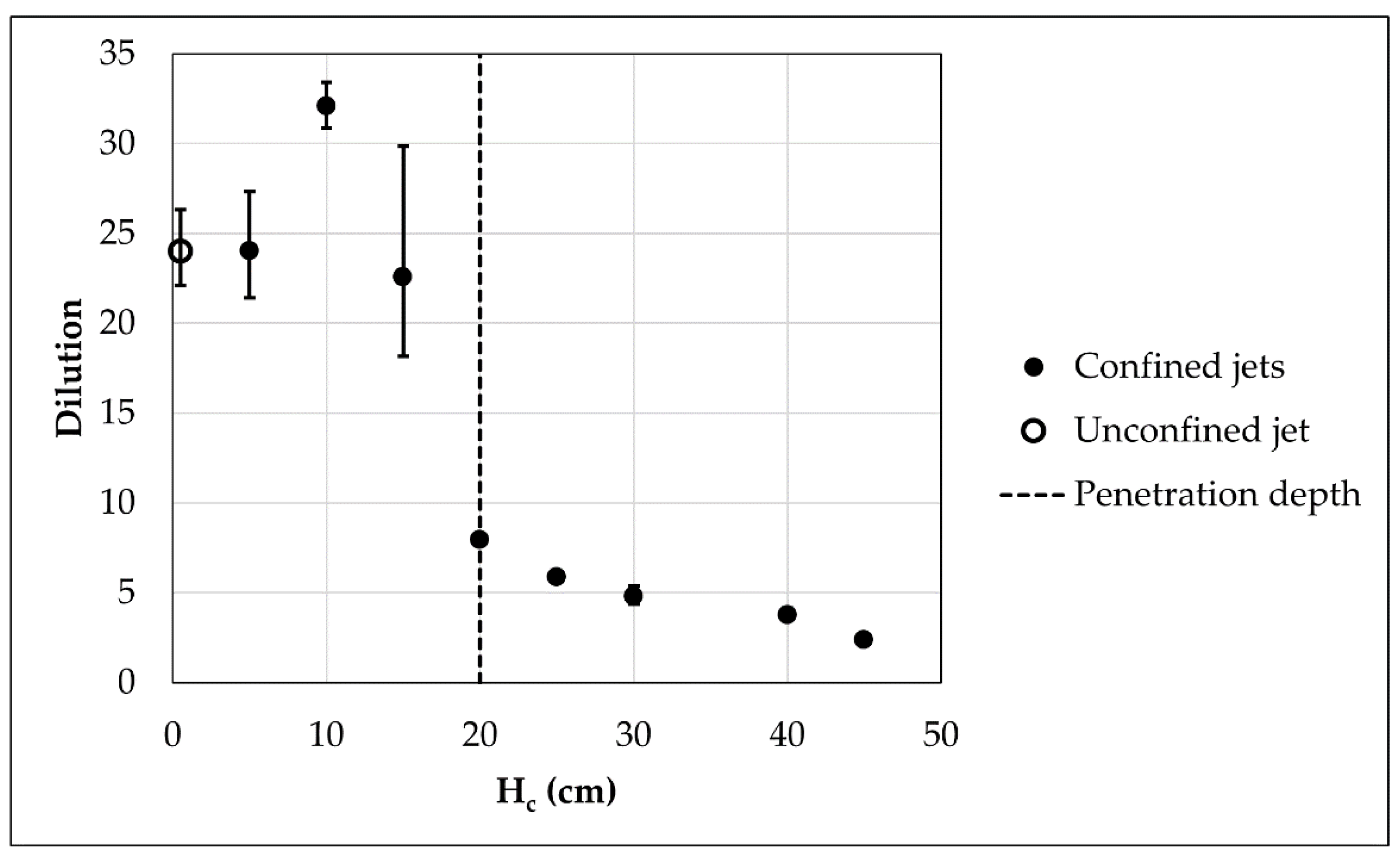
Two sets of experiments were conducted with Lj = 60 cm, Dc = 4.4 cm and ∆s = 10 psu to investigate the effect of downcomer submergence depth on the dilution of confined jets. For the first set (runs 9–16), the depth of receiving water was held constant at 50 cm and Hc was varied from 5 cm to 45 cm. For the second set (runs 14 and 23–25), the water depth was also varied along with Hc such that the distance between the bottom of the downcomer and the bottom of the tank (H–Hc) was held constant at 20 cm.
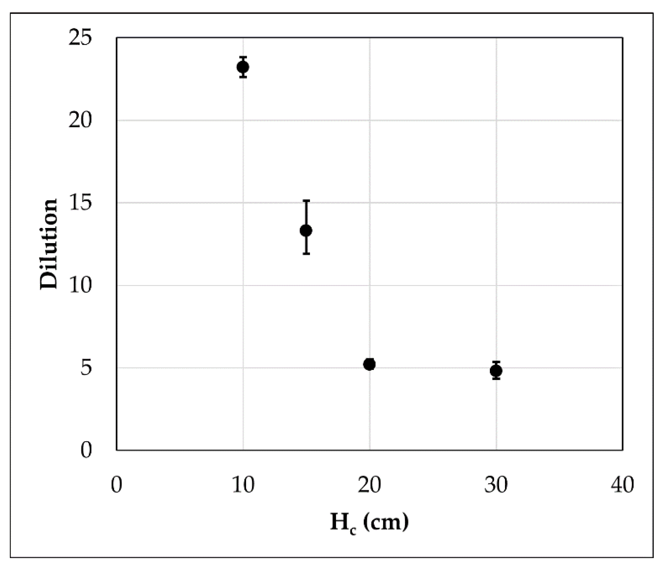
Figure 4 and Figure 5 show measured dilutions plotted as a function of Hc for the first and second sets of experiments, respectively. The dilution of an unconfined jet with Lj = 60 cm and ∆s = 10 psu (run 33) is also plotted in Figure 4 at Hc ≈ 0. The effect of Hc on dilution is non-monotonic for experiments with constant H, but dilution generally decreases with an increase in Hc. For experiments with fixed H–Hc, dilution decreases with an increase in Hc for small Hc, but becomes constant for large Hc.
For confined plunging jets, mixing with ambient water can occur both within the downcomer and outside the downcomer. The length of the eddy circulation region surrounding the jet is about 3–5Dc from the nozzle [31,32]. If the downcomer submergence is larger than this length, the jet is not able to entrain fresh water from outside (below) the downcomer and the entrainment demand is supplied by recirculated brine. Therefore, for long downcomers (Hc > 3–5Dc or Hc > 18 cm for Dc = 4.4 cm), most of the mixing with ambient water takes place after brine exits the downcomer and dilution depends on the depth of receiving water below the downcomer (H–Hc). Thus, dilution decreases with an increase in Hc for experiments with constant H (Figure 4), while the two runs with Hc = 20 and 30 cm have the same dilution when H–Hc is held constant (Figure 5). However, as seen in Figure 5, confined jets with short downcomers can get higher dilution with the same H–Hc because fresh water from outside can enter the downcomer allowing dilution to occur within the downcomer.
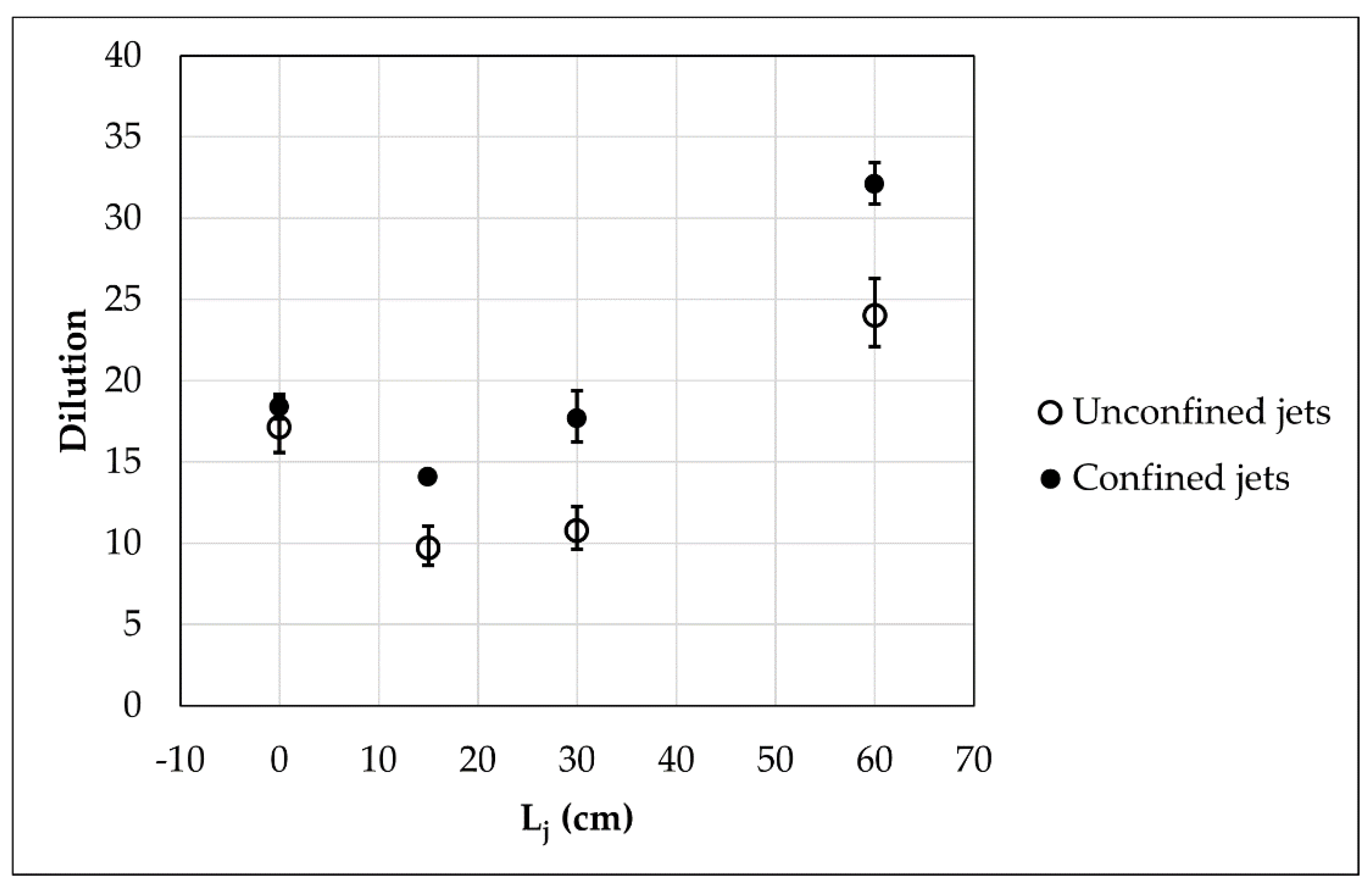
The bubble penetration depth for an unconfined jet with Lj = 60 cm and ∆s = 10 psu was measured to be 20 cm and is also shown in Figure 4. A confined jet designed to increase aeration (by pushing the bubbles deeper than an unconfined jet) will have Hc greater than 20 cm. The dilution of such confined plunging jets is less than the dilution of the unconfined jet. However, as shown in Figure 4, a confined jet can be designed to provide higher dilution than an unconfined jet by using a short downcomer (Hc = 10 cm). Experiments done with other jet lengths (Lj = 15 and 30 cm) also show higher dilution for a confined jet with Hc = 10 cm than that for an unconfined jet with the same jet length (Figure 6). The higher dilution for Hc = 10 cm as compared to the unconfined jet is likely because the presence of the downcomer reduces the momentum loss that the jet experiences upon impact with the water surface.
In addition to these runs, some other experiments with other values of Dc and ∆s also show that dilution decreases with increase in Hc for long downcomers.
4.2.2. Effect of Downcomer Diameter
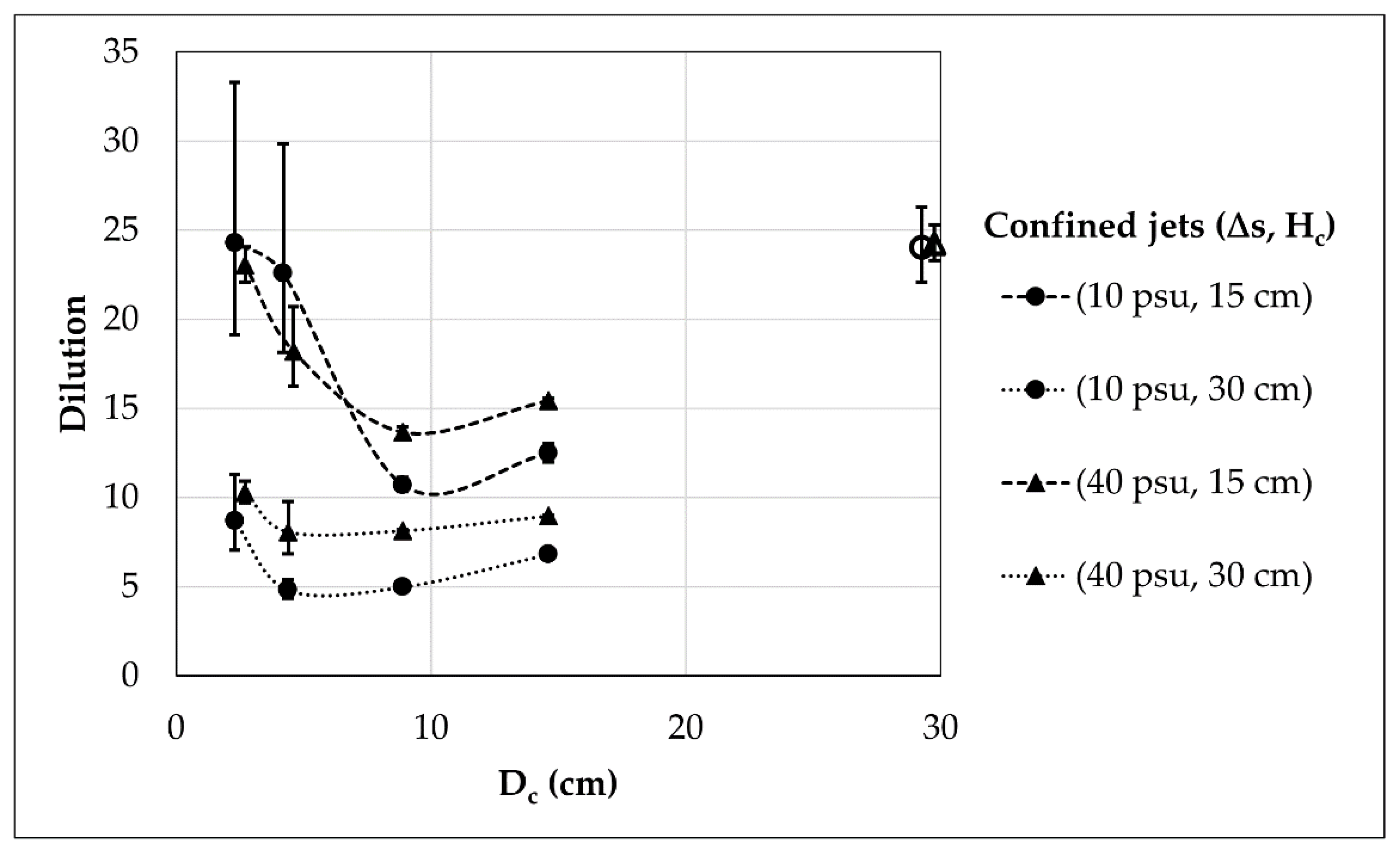
Experiments were conducted using downcomers with four different sizes to investigate the effect of downcomer diameter. For these experiments, the jet length was fixed at 60 cm, and two values of Hc (15 and 30 cm) and ∆s (10 and 40 psu) each were used. Figure 7 shows a plot of measured dilutions versus downcomer diameter. Dilution decreases with an increase in Dc for narrow downcomers, but increases with an increase in Dc for wide downcomers. This shift in dependence on Dc occurs at Dc between 5 and 10 cm (or Dc/d0 between 5 and 10) depending on the value of Hc.
For confined jets with long and narrow downcomers (for which most of the mixing takes place outside the downcomer), the flow of brine exiting from the bottom of the downcomer is uniform across its cross-section and the downward momentum of brine (M) decreases with increase in Dc (M = ρbQbv, where v = Qb/Ac(1 − n) is the downward velocity of brine inside the downcomer; n is the void ratio). Therefore, dilution also decreases with an increase in Dc.
For wide downcomers, the flow exiting from the bottom of the downcomer is not uniform (either radially or longitudinally). In fact, for some cases with large Dc and Hc (runs 2, 4, 6, and 8), no bubbles were seen escaping from the bottom of the downcomer suggesting non-uniform flow along the length of the downcomer (Figure 3). For confined jets with wide downcomers, dilution also takes place within the downcomer and the amount of ambient water available for entrainment within the downcomer increases with increase in Dc, resulting in an increase in dilution. This increase in dilution with Dc is expected to continue for wider downcomers and asymptotically approach the dilution of an unconfined jet.
Chow et al. [10] made measurements of the width of the bubble plume for unconfined jets which can be used to estimate the size of a downcomer that would behave similarly to an unconfined jet. For unconfined jets with similar flow rate but smaller jet lengths (15 or 30 cm) as the experiments done here, Chow et al. [10] measured the width of the bubble plume (W) to be between 14 and 20 cm. A downcomer with Dc > 2W (i.e., Dc greater than about 30–40 cm) should have enough “room” for entrainment and circulation of ambient water and should essentially behave as an unconfined jet.
4.2.3. Effect of Jet Length
As previously shown in Figure 6, the effect of jet length on both unconfined and confined plunging jets is non-monotonic and is the same as observed by Chow et al. [10]. This trend is explained by considering the momentum of the jet. As the jet accelerates due to gravity when it is falling through the headspace, its momentum also increases. Therefore, a jet with a longer Lj has higher momentum before it hits the water surface. However, the jet loses some of the momentum upon impact. The combination of these two effects leads to the non-monotonic trend with Lj. For Lj = 15 cm, the loss in momentum is more than the increase due to gravity resulting in lower dilution than a jet with Lj = 0. However, as Lj increases further, the increase in momentum due to gravity is larger than the loss due to impact, and dilution increases with Lj.
Other than the runs shown in Figure 6, all the other runs have Lj of 30 or 60 cm. The dilution for runs with Lj = 60 cm is higher than that of the corresponding runs with Lj = 30 cm because of the higher jet momentum.
4.2.4. Effect of Brine Salinity
The difference between dilution measurements for ∆s = 10 and 40 psu was small and a clear trend with brine salinity was not observed. While most experiments had higher dilution with ∆s = 40 psu, there are some cases for which the dilution was higher with ∆s = 10 psu and some for which the measured dilutions were equal for the two salinities (Figure 7 and Table 1).
Several factors govern the effect of ∆s on dilution. First, the relative vertical position of the fluorescence probe with respect to the centerline of the bottom layer (i.e., the tank floor) is different for experiments with different ∆s as the thickness of the bottom layer of diluted brine depends on the density (salinity) difference. The bottom layer is thinner for cases with higher density differences making the measurement location relatively farther from the centerline. Therefore, relatively lower concentration (compared to peak), i.e., higher dilution would be measured for ∆s = 40 psu. Second, in case of high dilution (absolute) for runs with ∆s = 10 psu, the density difference of diluted brine as compared to ambient water is small. In such cases, a well-defined bottom layer of diluted brine might not be formed; instead the diluted brine could be mixed over the water column resulting in high measured dilution. Third, the size of the bubbles decreases with increase in salinity [33]. Thus, it is possible that the movement of larger bubbles (for ∆s = 10 psu) generates some additional mixing leading to higher dilution.
5. Discussion
As discussed in the previous section, all the variables of importance (Hc, Dc, Lj and ∆s) affect dilution to differing extents, and in different ways, leading to complex, non-monotonic trends. This point is highlighted in Figure 7, which shows effects of Dc, Hc and ∆s on dilution. Figure 7 shows a significant reduction in dilution as Hc is increased from 15 to 30 cm for narrow downcomers. Change in downcomer diameter also leads to a significant change in dilution, especially when Dc is increased from 2.5 cm to 8.9 cm with Hc of 15 cm. As compared to the effects of Hc and Dc, the effect of ∆s on dilution is small.
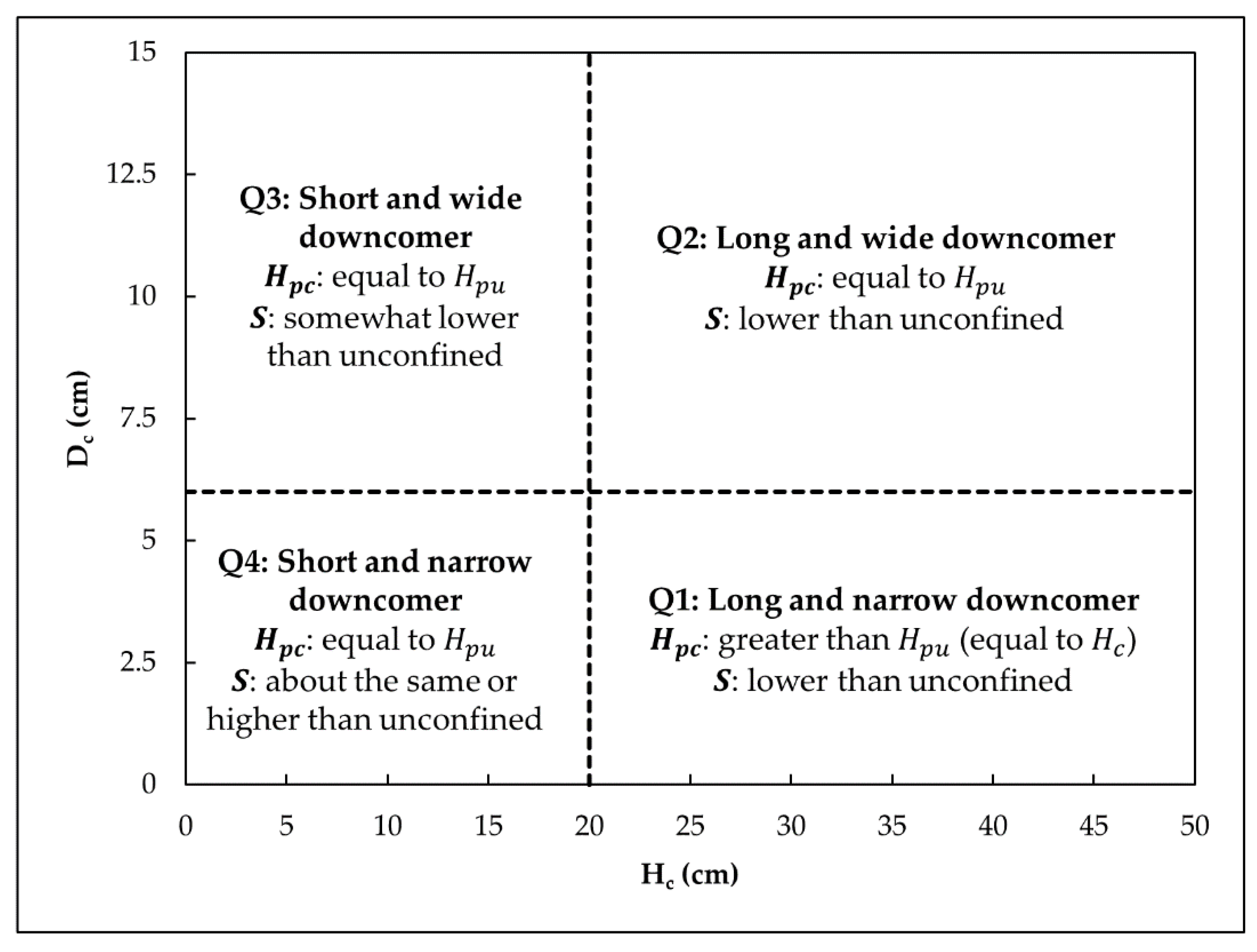
Results from the previous section can be used to discuss the effects of downcomer size (Hc and Dc) on bubble penetration depth and dilution. It is helpful to look at the effects of Hc and Dc by considering the four quadrants shown in Figure 8. For the experiments discussed here, the delineation between small and large Dc is made at Dc/d0 = 6. Short and long downcomers are delineated by comparing them to the bubble penetration depth of an unconfined jet (Hpu), which is equal to 20 cm.
The penetration depth of bubbles is only increased by using long and narrow downcomers (Q1). Increase in bubble penetration depth would result in longer contact time when the bubbles are rising to the surface and hence potential increase in aeration depending on the rate of air entrainment. However, the presence of a long and narrow downcomer results in lower dilution as compared to an unconfined jet.
For confined jets with wide downcomers (Q2 and Q3), the reduction in dilution as compared to an unconfined jet is smaller, but the penetration depth is also not increased. Thus, a confined jet with a wide downcomer is not expected to provide better aeration than an unconfined jet.
Confined jets with short and narrow downcomers (Q4) generally provide the same dilution as unconfined jets. However, using a confined jet with a short downcomer can result in higher dilution than an unconfined jet (Hc = 10 cm in the reported experiments). In this case, the bubble penetration depth was observed to be similar to an unconfined jet and both designs are expected to provide a comparable amount of aeration. Therefore, a design with a short downcomer might lead to an increase in dilution without a reduction in aeration. However, any benefit of this design with a downcomer will have to be weighed against a higher capital and operating (maintenance) cost.
In the above discussion, increase in bubble penetration depth is assumed to imply an increase in aeration because of the longer contact time between air and water. However, aeration also depends on the amount of net air entrained by the jet, which can be different for unconfined and confined plunging jets and also depends on the downcomer diameter and depth of submergence [22,26,29,30].
6. Summary and Conclusions
This paper evaluated confined plunging jets for disposal of reject brine from desalination plants. Previous studies had shown that confined plunging jets can be used to introduce air into the water column which can help reduce the possibility of low dissolved oxygen. However, it was not clear whether confined plunging jets can provide sufficient mixing of brine with ambient water to reduce its excess salinity. Therefore, experimental measurements of dilution of confined plunging jets discharging negatively buoyant effluent were presented in this paper. Dilution measurements showed non-monotonic dependence on important independent variables such as the jet length and the downcomer’s diameter and submergence depth. However, dilution generally decreased with an increase in downcomer submergence depth. No significant effect of brine salinity on dilution was observed.
Observations of the bubble penetration depth were also made and showed that confined plunging jets can increase the depth of penetration of bubbles in comparison to unconfined jets if long, narrow downcomers are used. The penetration depth of bubbles was roughly the same as unconfined jets with wide downcomers of any depth.
The experiments done in this study showed a potential trade-off between dilution and aeration. The use of long and narrow downcomers can increase the penetration depth of bubbles and therefore increase the contact time between the gas and liquid phase, but it also results in a reduction of dilution. Only for some experiments with short downcomers, which showed an increase in dilution and no reduction in bubble penetration depth, was this trade-off not apparent. However, experimental measurements of the change in dissolved oxygen, i.e., aeration, need to be made to see if a confined plunging jet with a short downcomer can indeed provide the same aeration as an unconfined plunging jet. Measurements of the change in dissolved oxygen (aeration) also need to be made for confined jets with long and narrow downcomers to prove that such designs can indeed provide better aeration.
Author Contributions
Conceptualization, E.E.A. and B.A.-A.; Formal analysis, I.S. and E.E.A.; Funding acquisition, E.E.A., B.A.-A. and J.H.; Investigation, I.S.; Methodology, E.E.A. and B.A.-A.; Project administration, E.E.A., B.A.-A. and J.H.; Supervision, E.E.A. and J.H.; Validation, I.S. and A.C.C.; Visualization, I.S.; Writing—original draft, I.S.; Writing—review & editing, I.S., E.E.A., B.A.-A., A.C.C. and J.H. All authors have read and agreed to the published version of the manuscript.
Funding
This research was supported by Kuwait-MIT Center for Natural Resources and the Environment (CNRE), which was funded by Kuwait Foundation for the Advancement of Sciences (KFAS), project no. PN1815EV07.
Data Availability Statement
All data generated during the study appear in the article.
Conflicts of Interest
The authors declare no conflict of interest. The funders had no role in the design of the study; in the collection, analyses, or interpretation of data; in the writing of the manuscript, or in the decision to publish the results.
Nomenclature
| a0 | cross-sectional area of the nozzle; |
| Ac | cross-sectional area of the downcomer; |
| c0 | discharge concentration of fluorescent dye (Rhodamine 6G); |
| cmean | average measured concentration of fluorescent dye (Rhodamine 6G); |
| CV | average coefficient of variation of measured concentrations for an experiment; |
| d0 | nozzle diameter; |
| Dc | downcomer diameter; |
| H | depth of receiving water; |
| Hc | submergence depth of downcomer below the surface of receiving water; |
| Hpc | for a confined jet, maximum depth below the surface of receiving water to which bubbles propagate; |
| Hpu | for an unconfined jet, maximum depth below the surface of receiving water to which bubbles propagate; |
| HR | rise of water level within the downcomer; |
| Lj | jet length (vertical distance between the tip of the nozzle and the receiving water surface); |
| Lr | ratio of lengths in the field vs in the lab; |
| M | downward momentum of brine exiting from the downcomer; |
| N | number of replicates of each experiment; |
| N | void ratio within the downcomer; |
| Qa | rate of net air entrained (amount of air that exits from the bottom of the downcomer); |
| Qb | brine flow rate; |
| Qg | rate of gross air entrained (total amount of air entrained by the jet which includes any air that is dis-entrained and rises to the surface within the downcomer); |
| Qr | ratio of flow rates in the field vs in the lab; |
| R | radial distance from the nozzle; |
| S | mean dilution; |
| v0 | exit velocity of brine from the nozzle; |
| V | downward velocity of brine exiting the downcomer; |
| W | width of the bubble plume for an unconfined plunging jet; |
| ∆s | excess salinity of brine; |
| ρb | density of brine; and |
| σmean | standard deviation of the mean measured concentration of fluorescent dye (Rhodamine 6G). |
References
- Lattemann, S.; Morelissen, R.; van Gils, J. Desalination capacity of the Arabian Gulf—Modeling, monitoring and managing discharges. In Proceedings of the International Desalination Association World Congress on Desalination and Water Reuse, Tianjin, China, 20–25 October 2013. [Google Scholar]
- Bleninger, T.; Jirka, G.H. Environmental Planning, Prediction and Management of Brine Discharges from Desalination Plants; Middle East Desalination Research Center (MEDRC): Muscat, Oman, 2010. [Google Scholar]
- Szeptycki, L.; Hartge, E.; Ajami, N.; Erickson, A.; Heady, W.N.; LaFeir, L.; Meister, B.; Verdone, L.; Kose, J.R. Marine and Coastal Impacts on Ocean Desalination in California. In A Report of Water in the West; Center for Ocean Solutions, Monterey Bay Aquarium and The Nature Conservancy: Monterey, CA, USA, 2016. [Google Scholar]
- Missimer, T.M.; Maliva, R.G. Environmental issues in seawater reverse osmosis desalination: Intakes and outfalls. Desalination 2018, 434, 198–215. [Google Scholar] [CrossRef]
- Jones, E.; Qadir, M.; van Vliet, M.T.H.; Smakhtin, V.; Kang, S. The state of desalination and brine production: A global outlook. Sci. Total Environ. 2019, 657, 1343–1356. [Google Scholar] [CrossRef] [PubMed]
- Roberts, P.J.W.; Jenkins, S.; Paduan, J.; Schlenk, D.; Weis, J. Management of Brine Discharges to Coastal Waters, Recommendations of a Science Advisory Panel; State Water Resources Control Board: Sacramento, CA, USA, 2012. [Google Scholar]
- Jiang, B.; Law, A.W.K.; Lee, J.H.W. Mixing of 30° and 45° Inclined Dense Jets in Shallow Coastal Waters. J. Hydraul. Eng. 2014, 140, 241–253. [Google Scholar] [CrossRef]
- Shrivastava, I.; Adams, E.E. Pre-dilution of desalination reject brine: Impact on outfall dilution in different water depths. J. Hydro Environ. Res. 2019, 24, 28–35. [Google Scholar] [CrossRef]
- Shrivastava, I.; Adams, E.E. Effect of shallowness on dilution of unidirectional diffusers. J. Hydraul. Eng. 2019, 145, 06019013. [Google Scholar] [CrossRef]
- Chow, A.C.; Shrivastava, I.; Adams, E.E.; Al-Rabaie, F.; Al-Anzi, B. Unconfined dense plunging jets used for brine disposal from desalination plants. Processes 2020, 8, 696. [Google Scholar] [CrossRef]
- Hodges, B.R. The importance of mixing and isolation time for desalination brine discharge. In Proceedings of the International Engineering Conference on Hot Arid Regions (IECHAR 2010), Al-Ahsa, Saudi Arabia, 1–2 March 2010. [Google Scholar]
- Hodges, B.R.; Furnans, J.E.; Kulis, P.S. Thin-Layer Gravity Current with Implications for Desalination Brine Disposal. J. Hydraul. Eng. 2011, 137, 356–371. [Google Scholar] [CrossRef]
- Adams, E.E.; Shrivastava, I.; Chow, A.C. Vertical mixing of desalination reject brine that accumulates in local depressions after near field mixing. In Proceedings of the International Symposium on Outfall Systems (ISOS), Ottawa, ON, Canada, 10–13 May 2016. [Google Scholar]
- Pietrafesa, L.J.; Miller, J.M. A Comparison of Fish Kills in the Pamlico and Neuse Rivers (a Symptom) and Implications for Estuarine Health; North Carolina State University: Raleigh, NC, USA, 1997. [Google Scholar]
- Nestlerode, J.A.; Diaz, R.J. Effects of periodic environmental hypoxia on predation of a tethered Polychaete, Glycera americana: Implications for trophic dynamics. Mar. Ecol. Prog. Ser. 1998, 172, 185–195. [Google Scholar] [CrossRef] [Green Version]
- Lin, J.; Lian, X.; Pietrafesa, L.J.; Shen, J.; Mallin, M.A.; Durako, M.J. Dissolved oxygen stratification in two micro-tidal partially-mixed estuaries. Estuar. Coast. Shelf Sci. 2006, 70, 423–437. [Google Scholar] [CrossRef]
- USGS Dissolved Oxygen Solubility Tables. Available online: https://water.usgs.gov/water-resources/software/DOTABLES/ (accessed on 9 April 2021).
- Stanley, D.W.; Nixon, S.W. Stratification and bottom-water hypoxia in the Pamlico River Estuary. Estuaries 1992, 15, 270–281. [Google Scholar] [CrossRef]
- Buzzelli, C.P.; Luettich, R.A., Jr.; Powers, S.P.; Peterson, C.H.; McNinch, J.E.; Pinckney, J.L.; Paerl, H.W. Estimating the spatial extent of bottomwater hypoxia and habitat degradation in a shallow estuary. Mar. Ecol. Prog. Ser. 2002, 230, 103–112. [Google Scholar] [CrossRef]
- Breitburg, D.L.; Adamack, A.; Rose, K.A.; Kolesar, S.E.; Decker, M.B.; Purcell, J.E.; Keister, J.E.; Cowan, J.H., Jr. The pattern and influence of low dissolved oxygen in the Patuxent River, a seasonal hypoxic estuary. Estuaries 2003, 26, 280–297. [Google Scholar] [CrossRef]
- Yamagiwa, K.; Oochira, Y.; Ohkawa, A. Performance evaluation of plunging liquid jet bioreactor with crossflow filtration for small-scale treatment of domestic wastewater. Bioresour. Technol. 1994, 58, 131–138. [Google Scholar] [CrossRef]
- Bin, A.K. Gas entrainment by plunging liquid jets. Chem. Eng. Sci. 1993, 48, 3585–3630. [Google Scholar] [CrossRef]
- Horan, N.J. Biological Wastewater Treatment System: Theory and Operation; John Wiley and Sons: Hoboken, NJ, USA, 1990; p. 60. [Google Scholar]
- Low, K.C. Hydrodynamics and Mass Transfer Studies of a Confined Plunging Jet. Ph.D. Thesis, Department of Chemical Engineering, Loughborough University, Loughborough, UK, 2003. [Google Scholar]
- Van de Donk, J.A.C. Water aeration with plunging jets. Ph.D. Thesis, Department of Applied Sciences, Delft University of Technology, Delft, The Netherlands, 1981. [Google Scholar]
- Ohkawa, A.; Kusabiraki, D.; Kawai, Y.; Sakai, S.; Endoh, K. Some flow characteristics of a vertical liquid jet system having downcomers. Chem. Eng. Sci. 1986, 41, 2347–2361. [Google Scholar] [CrossRef]
- Deswal, S.; Verma, D.V.S. Air-water oxygen transfer with multiple jets. Water Qual. Res. J. 2007, 42, 295–302. [Google Scholar] [CrossRef]
- Ma, J.; Oberai, A.A.; Drew, D.A.; Lahey, R.T., Jr.; Moraga, F.J. A quantitative sub-grid entrainment model for bubbly flows—Plunging jets. Comput. Fluids 2010, 39, 77–86. [Google Scholar] [CrossRef]
- Cumming, I.W.; Rielly, C.D.; Mason, A.J. Hydraulic performance of an annular plunging jet reactor. Chem. Eng. Res. Des. 2002, 80, 543–549. [Google Scholar] [CrossRef]
- Al-Anzi, B.; Cumming, I.W.; Rielly, C.D. Air entrainment rates in a confined plunging jet reactor. In Proceedings of the 10th International Conference on Multiphase Flow in Industrial Plants, Tropea, Italy, 20–23 September 2006; pp. 71–82. [Google Scholar]
- Al-Anzi, B. Effect of Primary Variables on A Confined Plunging Liquid Jet Reactor. Water 2020, 12, 764. [Google Scholar] [CrossRef] [Green Version]
- Bayly, A.E.; Rielly, C.D.; Evans, G.M.; Hazell, M. The rate of expansion of a confined submerged jet. Proceedings of CHEMECA ’92, Canberra, Australia, 1 January 1992; pp. 119–126. [Google Scholar]
- Clift, R.; Grace, J.R.; Weber, M.E. Bubbles, Drops and Particles; Dover: Mineola, NY, USA, 1978. [Google Scholar]
Figure 1.
Different types of outfalls for the discharge of brine: (a) Surface discharge, (b) momentum dominated submerged multiport discharge, (c) buoyancy dominated surface multiport discharge, (d) unconfined plunging jets, and (e) confined plunging jets. Diluted brine from any of these outfalls can spread along the seafloor and result in a thin layer with low dissolved oxygen (f). (Figure modified from [10].)

Figure 2.
Definition sketch for a confined plunging jet reactor.

Figure 3.
Side view of the bubble plume within the downcomer for experiments with Lj = 60 cm and ∆s = 10 psu.
Figure 3.
Side view of the bubble plume within the downcomer for experiments with Lj = 60 cm and ∆s = 10 psu.

Figure 4.
Dilution measurements for confined plunging jet experiments with H = 50 cm, Lj = 60 cm, Dc = 4.4 cm and ∆s = 10 psu. (Dilution of an unconfined plunging jet with H = 50 cm, Lj = 60 cm and ∆s = 10 psu is plotted at Hc ≈ 0.)
Figure 4.
Dilution measurements for confined plunging jet experiments with H = 50 cm, Lj = 60 cm, Dc = 4.4 cm and ∆s = 10 psu. (Dilution of an unconfined plunging jet with H = 50 cm, Lj = 60 cm and ∆s = 10 psu is plotted at Hc ≈ 0.)

Figure 5.
Dilution measurements for confined plunging jet experiments with H–Hc = 20 cm, Lj = 60 cm, Dc = 4.4 cm and ∆s = 10 psu.
Figure 5.
Dilution measurements for confined plunging jet experiments with H–Hc = 20 cm, Lj = 60 cm, Dc = 4.4 cm and ∆s = 10 psu.

Figure 6.
Comparison of dilution of confined jets with Hc = 10 cm and unconfined jets. (∆s = 10 psu for both unconfined and confined jets, Dc = 4.4 cm for the confined jets.).
Figure 6.
Comparison of dilution of confined jets with Hc = 10 cm and unconfined jets. (∆s = 10 psu for both unconfined and confined jets, Dc = 4.4 cm for the confined jets.).

Figure 7.
Plot of measured dilution as a function of downcomer diameter for experiments with Lj = 60 cm. Dilution of unconfined jets is shown at large Dc (≈ 30 cm). (The abscissas of some runs are shifted slightly to avoid overlap.).
Figure 7.
Plot of measured dilution as a function of downcomer diameter for experiments with Lj = 60 cm. Dilution of unconfined jets is shown at large Dc (≈ 30 cm). (The abscissas of some runs are shifted slightly to avoid overlap.).

Figure 8.
Bubble penetration depth (Hpc) and dilution (S) of confined plunging jets as functions of downcomer dimensions (Hc and Dc). (The delineation between small and large Dc is made at Dc/d0 = 6. Short and long downcomers are delineated by comparing them to the bubble penetration depth of an unconfined jet (Hpu) which is equal to 20 cm.)


Table 1.
Experimental parameters.
| Run | Lj (cm) | Dc (cm) | ∆s (psu) | Hc (cm) | H (cm) | N | cmean/c0 | σmean/c0 | CV (%) | S | Range of S | HR (cm) |
|---|---|---|---|---|---|---|---|---|---|---|---|---|
| 1 | 60 | 14.6 | 10 | 15 | 50 | 3 | 0.08 | 0.003 | 18 | 12 | 11.5–12.5 | 1 |
| 2 | 60 | 14.6 | 10 | 30 | 50 | 3 | 0.15 | 0.002 | 15 | 7 | 6.9–7.1 | 1 |
| 3 | 60 | 14.6 | 40 | 15 | 50 | 3 | 0.06 | 0.0005 | 14 | 15 | 14.9–15.1 | 1 |
| 4 | 60 | 14.6 | 40 | 30 | 50 | 3 | 0.11 | 0.001 | 15 | 9 | 8.96–9.04 | 1 |
| 5 | 60 | 8.9 | 10 | 15 | 50 | 4 | 0.09 | 0.004 | 13 | 11 | 10.6–11.4 | 2.5 |
| 6 | 60 | 8.9 | 10 | 30 | 50 | 3 | 0.20 | 0.010 | 14 | 5 | 4.8–5.3 | 3 |
| 7 | 60 | 8.9 | 40 | 15 | 50 | 4 | 0.07 | 0.002 | 10 | 14 | 13.7–14.3 | 2 |
| 8 | 60 | 8.9 | 40 | 30 | 50 | 3 | 0.12 | 0.001 | 13 | 8 | 7.9–8.1 | 2.5 |
| 9 | 60 | 4.4 | 10 | 5 | 50 | 5 | 0.04 | 0.005 | 27 | 24 | 21.4–27.3 | −1 |
| 10 | 60 | 4.4 | 10 | 10 | 50 | 6 | 0.03 | 0.001 | 14 | 32 | 30.8–33.3 | 0.5 |
| 11 | 60 | 4.4 | 10 | 15 | 50 | 10 | 0.04 | 0.011 | 23 | 23 | 18.6–30.3 | 5 |
| 12 | 60 | 4.4 | 10 | 20 | 50 | 4 | 0.13 | 0.003 | 8 | 8 | 7.8–8.2 | 9.5 |
| 13 | 60 | 4.4 | 10 | 25 | 50 | 4 | 0.17 | 0.004 | 10 | 6 | 5.9–6.1 | 13 |
| 14 | 60 | 4.4 | 10 | 30 | 50 | 5 | 0.21 | 0.022 | 19 | 5 | 4.5–5.6 | 18 |
| 15 | 60 | 4.4 | 10 | 40 | 50 | 3 | 0.26 | 0.024 | 36 | 4 | 3.7–4.4 | 25.5 |
| 16 | 60 | 4.4 | 10 | 45 | 50 | 3 | 0.42 | 0.024 | 30 | 2 | 1.9–2.1 | 29.5 |
| 17 | 60 | 4.4 | 40 | 15 | 50 | 5 | 0.05 | 0.007 | 15 | 18 | 16.0–20.5 | 4 |
| 18 | 60 | 4.4 | 40 | 30 | 50 | 6 | 0.12 | 0.022 | 27 | 8 | 6.8–9.7 | 17 |
| 19 | 60 | 2.5 | 10 | 15 | 50 | 4 | 0.04 | 0.011 | 22 | 24 | 18.8–33.0 | −4 |
| 20 | 60 | 2.5 | 10 | 30 | 50 | 5 | 0.12 | 0.027 | 44 | 9 | 7.4–11.6 | 4.5 |
| 21 | 60 | 2.5 | 40 | 15 | 50 | 4 | 0.04 | 0.002 | 19 | 23 | 22.0–24.0 | −5 |
| 22 | 60 | 2.5 | 40 | 30 | 50 | 4 | 0.10 | 0.006 | 25 | 10 | 9.4–10.7 | 3 |
| 23 | 60 | 4.4 | 10 | 20 | 40 | 3 | 0.19 | 0.011 | 12 | 5 | 4.7–5.3 | 10 |
| 24 | 60 | 4.4 | 10 | 15 | 35 | 4 | 0.08 | 0.009 | 35 | 13 | 11.6–14.8 | 5 |
| 25 | 60 | 4.4 | 10 | 10 | 30 | 2 | 0.04 | 0.001 | 20 | 23 | 22.4–23.6 | −0.5 |
| 26 | 30 | 4.4 | 10 | 10 | 50 | 3 | 0.06 | 0.005 | 19 | 18 | 16.6–19.7 | −0.5 |
| 27 | 30 | 4.4 | 10 | 15 | 50 | 4 | 0.10 | 0.011 | 14 | 10 | 9.1–11.2 | 3 |
| 28 | 30 | 4.4 | 10 | 30 | 50 | 4 | 0.20 | 0.020 | 24 | 5 | 4.5–5.5 | 13.5 |
| 29 | 30 | 4.4 | 40 | 15 | 50 | 3 | 0.08 | 0.005 | 17 | 13 | 12.2–13.9 | 2.5 |
| 30 | 30 | 4.4 | 40 | 30 | 50 | 4 | 0.13 | 0.019 | 22 | 8 | 7.0–9.3 | 12 |
| 31 | 15 | 4.4 | 10 | 10 | 50 | 2 | 0.07 | 0.001 | 20 | 14 | 13.8–14.2 | |
| 32 | 0 | 4.4 | 10 | 10 | 50 | 3 | 0.05 | 0.002 | 16 | 18 | 17.3–18.8 | |
| 33 | 60 | 10 | 50 | 9 | 0.04 | 0.004 | 25 | 24 | 22.1–26.3 | |||
| 34 | 60 | 40 | 50 | 4 | 0.04 | 0.002 | 13 | 24 | 23.0–25.0 | |||
| 35 | 30 | 10 | 50 | 4 | 0.09 | 0.011 | 24 | 11 | 9.8–12.5 | |||
| 36 | 30 | 40 | 50 | 3 | 0.06 | 0.002 | 17 | 17 | 16.4–17.6 | |||
| 37 | 15 | 10 | 50 | 3 | 0.10 | 0.013 | 15 | 10 | 8.9–11.4 | |||
| 38 | 0 | 10 | 50 | 3 | 0.06 | 0.006 | 14 | 17 | 15.4–18.9 |
Publisher’s Note: MDPI stays neutral with regard to jurisdictional claims in published maps and institutional affiliations. |
© 2021 by the authors. Licensee MDPI, Basel, Switzerland. This article is an open access article distributed under the terms and conditions of the Creative Commons Attribution (CC BY) license (https://creativecommons.org/licenses/by/4.0/).
Share and Cite
MDPI and ACS Style
Shrivastava, I.; Adams, E.E.; Al-Anzi, B.; Chow, A.C.; Han, J. Confined Plunging Liquid Jets for Dilution of Brine from Desalination Plants. Processes 2021, 9, 856. https://doi.org/10.3390/pr9050856
AMA Style
Shrivastava I, Adams EE, Al-Anzi B, Chow AC, Han J. Confined Plunging Liquid Jets for Dilution of Brine from Desalination Plants. Processes. 2021; 9(5):856. https://doi.org/10.3390/pr9050856
Chicago/Turabian StyleShrivastava, Ishita, Edward Eric Adams, Bader Al-Anzi, Aaron Chunghin Chow, and Jongyoon Han. 2021. "Confined Plunging Liquid Jets for Dilution of Brine from Desalination Plants" Processes 9, no. 5: 856. https://doi.org/10.3390/pr9050856
Note that from the first issue of 2016, this journal uses article numbers instead of page numbers. See further details here.