
3D-Printed Quasi-Absolute Electromagnetic Encoders for Chipless-RFID and Motion Control Applications


CIMITEC, Departament d’Enginyeria Electrònica, Universitat Autònoma de Barcelona, 08193 Bellaterra, Spain
*
Author to whom correspondence should be addressed.
Electronics 2021, 10(10), 1154; https://doi.org/10.3390/electronics10101154
Submission received: 20 April 2021
/
Revised: 6 May 2021
/
Accepted: 11 May 2021
/
Published: 13 May 2021
(This article belongs to the Special Issue Advances in Chipless RFID Technology)
Abstract
:This paper presents electromagnetic encoders useful for chipless-RFID and motion control applications. The encoders consist in a pair of linear chains of rectangular apertures implemented by means of 3D printing. One of these chains is periodic and acts as a clock, whereas the other chain contains an identification (ID) code. With these two aperture chains, the ID code can be synchronously read, so that the relative velocity between the tag and the reader is irrelevant. Additionally, it is shown in the paper that by properly designing the reader, it is possible to determine the motion direction. The sensitive part of the reader is a microstrip line loaded with three complementary split ring resonators (CSRRs) etched in the ground plane and fed by three harmonic signals. By encoder motion, the characteristics of the local medium surrounding the CSRRs are modified, and the harmonic signals are amplitude modulated (AM) at the output port of the line, thereby providing the clock signal (which gives the encoder velocity), the ID code (providing also the quasi-absolute position) and the direction of motion. A fabricated prototype encoder is characterized by reading it with a dedicated reader.
1. Introduction
Optical encoders [1,2,3,4] are the most genuine and widespread technology for motion control applications. As the encoder moves across an optical beam generated by an optical source, typically a laser diode, a chain of apertures made on a (typically) metallic substrate are detected. When an aperture crosses the optical beam, the encoder is transparent and an optical detector, placed on the other side of the encoder, can record the optical beam in the form of a pulse. Thus, as many pulses as apertures are detected by the optical reader. Obviously, the encoders can be implemented with several chains of apertures, which can be codified, and therefore can be used to determine the absolute position of the encoder [5,6]. These absolute encoder systems are able to provide the position regardless of the previous motion stages of the encoder, contrary to the so-called incremental-type encoders, where the position is determined from the cumulative number of pulses (i.e., through pulse counting).
Electromagnetic encoders [7,8,9,10,11,12,13,14,15,16] are an alternative to optical encoders. Both systems exhibit a similar working principle, but the optical signals are replaced by microwave signals. In electromagnetic systems, the encoders can be made of chains of apertures, or also chains of inclusions (metallic or dielectric). However, these encoders should not be confused with the so-called magnetic encoders, based on magnets or inductive elements [17,18,19,20,21,22,23,24]. The first reported electromagnetic encoders were implemented by etching circular chains of metallic inclusions (planar resonators) in the periphery of a dielectric disc [25] (these encoders indeed appeared as an evolution of previous angular displacement sensors based on coupling modulation between a microstrip line and a single circular resonator axial to the rotor [26,27,28]). Such rotary encoders were incremental, i.e., only able to provide the angular position from the cumulative number of peaks in the envelope function (nevertheless, in one of the implementations [10], the motion direction, clockwise or counter-clockwise, was detected by adding a non-periodic chain). In order to detect these inclusions, the sensitive part of the reader consists of a microstrip line structure fed by at least a harmonic signal. Typically, as many harmonic signals as inclusion chains are needed for inferring all the relevant information provided by the encoder, e.g., the velocity and the absolute position. By encoder motion, the harmonic signal/s is/are amplitude modulated (AM) at the output port of the line, and the relevant information is contained in the envelope function/s, in the form of peaks or dips (equivalent to the pulses in the optical encoders).
Recently, all-dielectric electromagnetic encoders, either based on apertures or dielectric inclusions made on a dielectric substrate, were reported [15,29,30]. As compared with encoders based on metallic inclusions, the main advantage of all-dielectric encoders is the superior robustness against wearing or friction. This robustness has also been demonstrated in encoders based on metallic inclusions, but implemented in the form of metallic patches [14]. Another recent advance concerns the implementation of electromagnetic encoders with synchronous reading, where at least two inclusion chains are needed, one acting as the clock, with all the inclusions present at their predefined positions, and the other one containing the ID code [14,15,16,31,32,33]. In [16,32], not only the encoders exhibit synchronous reading capability, but also the motion direction can be determined.
Electromagnetic encoders can be used in motion control applications, but also in other applications such as chipless-RFID [34,35]. By eliminating some of the inclusions of the encoder, an ID code can be obtained. Contrary to most chipless-RFID tags based on frequency domain, time domain, or exploiting various domains simultaneously [36,37,38,39,40,41,42,43,44,45,46,47,48,49,50,51,52,53,54,55,56,57,58,59,60,61,62,63,64], the encoder-based tags should be read by proximity, through the near field, and bit to bit, i.e., sequentially [65,66,67]. This represents a limitation in certain applications, e.g., when read distances of at least various cm are required. The number of bits of electromagnetic encoder-based chipless tags is only limited by tag size [12,68], these representing an advantage over other chipless-RFID approaches. In certain applications, such as secure paper, authentication of premium products [69], etc., reading by proximity is not necessarily an issue (indeed, it can even provide certain level of confidence against spying or eavesdropping). It is important to bear in mind that, although this electromagnetic encoders have been focused on motion control applications, as well as chipless-RFID, applications such as motion detector [70], monitoring process in industrial scenarios [71,72], or smart packaging, for example, can be also of potential application.
In the present paper, the main objective was to present an electromagnetic encoder system with synchronous reading and motion direction detection capability, based on 3D-printed encoders with aperture chains. This is the first all-dielectric encoder able to provide such complete functionality. Namely, it is able to provide the encoder velocity, the motion direction, as well as the (quasi) absolute position, from the codified chain of apertures (to be discussed later).
2. The Proposed Encoder and Reader, and Working Principle
The general working principle of the proposed all-dielectric electromagnetic encoders is AM modulation of the harmonic feeding signals caused by encoder motion over the sensitive part of the reader. Nevertheless, we should give more details, since the proposed encoder system is able to provide the encoder velocity, the quasi absolute position and the direction of motion. For that purpose, two chains of apertures are required. One chain is periodic, i.e., all the apertures are present at predefined positions, and the period is designated as p. Such chain is designated as clock or velocity chain, as far as it provides the clock signal, as well as the encoder velocity. In the other chain, the positions of the apertures are identical, however, not all the apertures are present at those positions. By this means, an ID code is provided to this second chain, designated as ID chain, or position chain. In applications of the encoders as chipless-RFID tags, the ID code can be arbitrary. The clock chain gives the instants of time to read the ID code from the ID code chain. By contrast, as position sensor able to determine the quasi-absolute position, the ID code should not be arbitrary. It should be selected according to the De Bruijn sequence [73]. Let us explain the reason next.
Let us consider that the total length of the encoder is L. The number of different discrete positions that must be codified in order to determine the relative position of the encoder with regard to the reader is thus L/p. Therefore, the number of bits necessary to unequivocally differentiating the discrete positions of the encoder should satisfy
Implementing as many aperture chains as number of bits N is not a realistic solution because it represents a penalty in terms of encoder size. However, if the ID code of the complete (single) position chain follows the De Bruijn sequence, any sub-set of N sequential bits is unique (it is different to any other). Therefore, the bit corresponding to a certain position, plus the N—1 bits of the previous positions univocally determine the position. However, it is necessary to know the direction of motion, and, moreover, after a system reset, the encoder must be displaced N positions before an absolute position can be determined. For this main reason, the designation of these encoders should be quasi-absolute, rather than absolute.
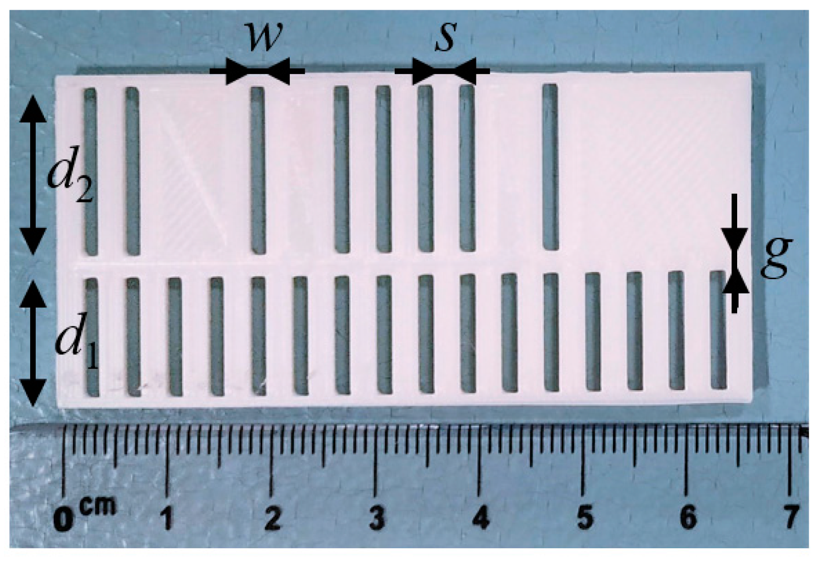
The photograph of the fabricated 16-bit encoder is depicted in Figure 1. The encoder was 3D-printed by means of the Ultimaker 3 Extended 3D printer, using dielectric Polylactic Acid (PLA) as filament. Prior to the implementation of the encoder, and in order to obtain the dielectric constant of the PLA by means of a Keysight 85072A 10-GHz Split Cylinder Resonator, a square-shape slab sample (the dimensions are provided by the split cylinder resonator) was printed. The measured dielectric constant of this dielectric PLA is εr = 3, although this value can slightly suffer variations depending on the PLA properties [74,75].
After having measured the dielectric constant, the encoder was fabricated using the following printer parameters: nozzle size 0.44 mm, printing temperature 200 °C, build plate (or bed plate) temperature 60 °C, printing speed 70 mm/s and infill density 100%. The (rectangular) apertures of both chains, if present, are located at identical positions, as indicated before. The dimensions of the encoder were optimized, according to electromagnetic simulations, as it will be later shown. It is also important to emphasize that other dielectric substrates, even flexible [76], could be used as encoders, but in this case, we took advantage of the high versatility and faster fabrication process of 3D printing, previously demonstrated in the RFID devices [77,78,79].
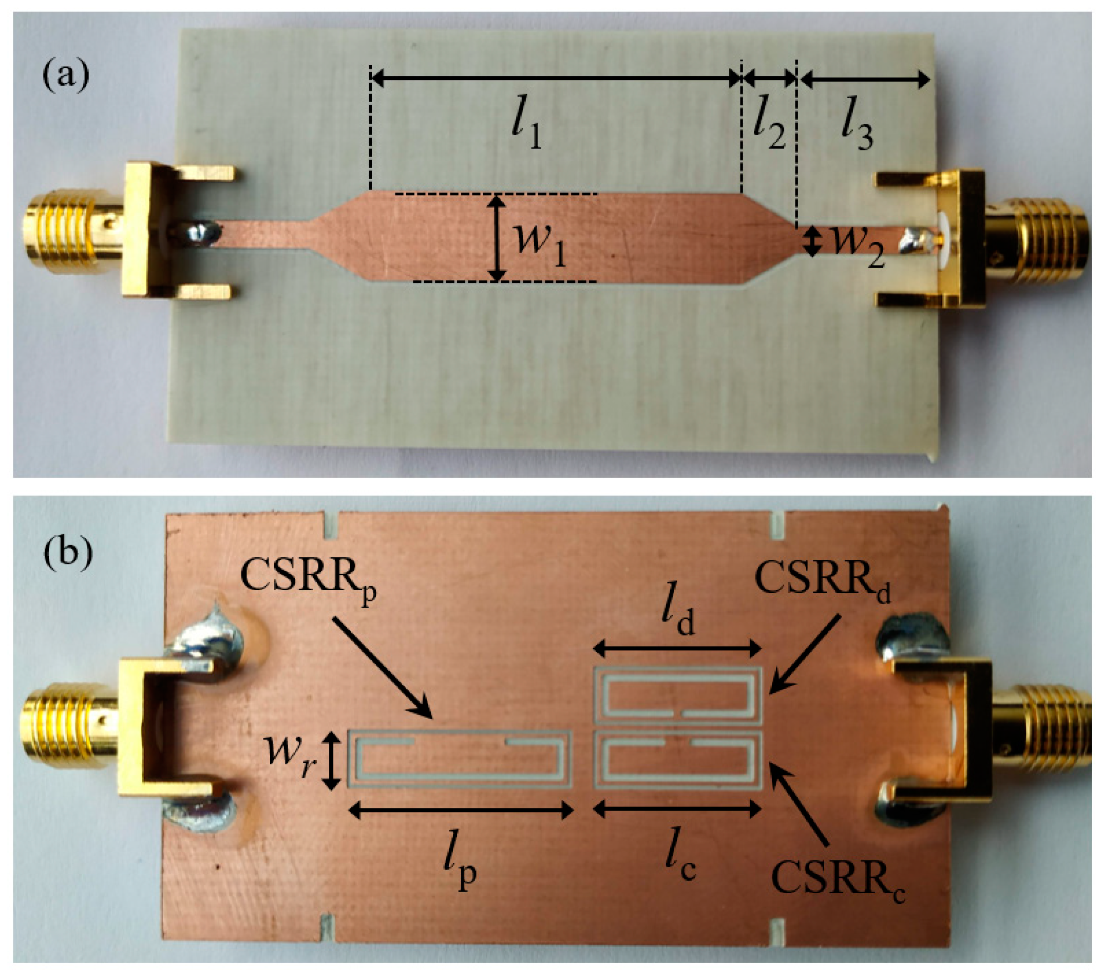
Concerning the sensitive part of the reader, it consists of a microstrip line loaded with three complementary split ring resonators (CSRRs) etched in the ground plane, as Figure 2 illustrates. It has been demonstrated that CSRR-loaded lines are efficient permittivity sensors, based on the variation experienced by the resonance frequency when a certain material under test (MUT) is placed on top of the resonator [80,81,82,83,84,85]. Indeed, the reported encoders exhibit a significant permittivity contrast between the apertures (with εr = 1) and the substrate (PLA with εr = 3). Consequently, it is expected that, by encoder motion, the presence of PLA on top of the sensitive part of the reader (i.e., the absence of the apertures) shifts down the resonance frequency of the resonant elements. Note that if the quality factor of the CSRRs is significant, the excursion experienced by the transmission coefficient at the frequency of resonance of the CSRR covered by the substrate should be high, a necessary condition to ensure the functionality and robustness of the system.
Note that the presence of three CSRRs obeys the fact that, in order to obtain the encoder velocity (and clock signal), the quasi-absolute position, and the motion direction, three signals are needed. The three CSRRs are tuned to different frequencies, and can be labeled by sub-indexes, in order to differentiate between the position resonator, CSRRp, the clock resonator CSRRc, and the motion direction resonator CSRRd.
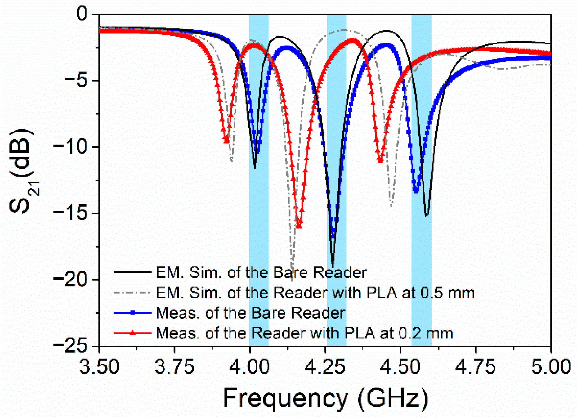
The electromagnetic simulation of the bare reader is shown in Figure 3, where the three notches corresponding to the frequencies coherently designated as fp = 4.030 GHz, fc = 4.300 GHz and fd = 4.570 GHz can be seen. These notches (or dips) reflect the injected signals at the frequencies of interest. This situation corresponds to the encoder apertures, which can be assigned the logic state “1”. However, as previously mentioned, the presence of PLA at certain distance on top of the sensitive part of the reader shifts down the whole frequency response. Thus, instead of having a notch or dip at the frequencies of interest, the presence of this dielectric substrate allows the signal to be transmitted (equivalent to the logic state “0”), as can be observed in the graph of Figure 3.
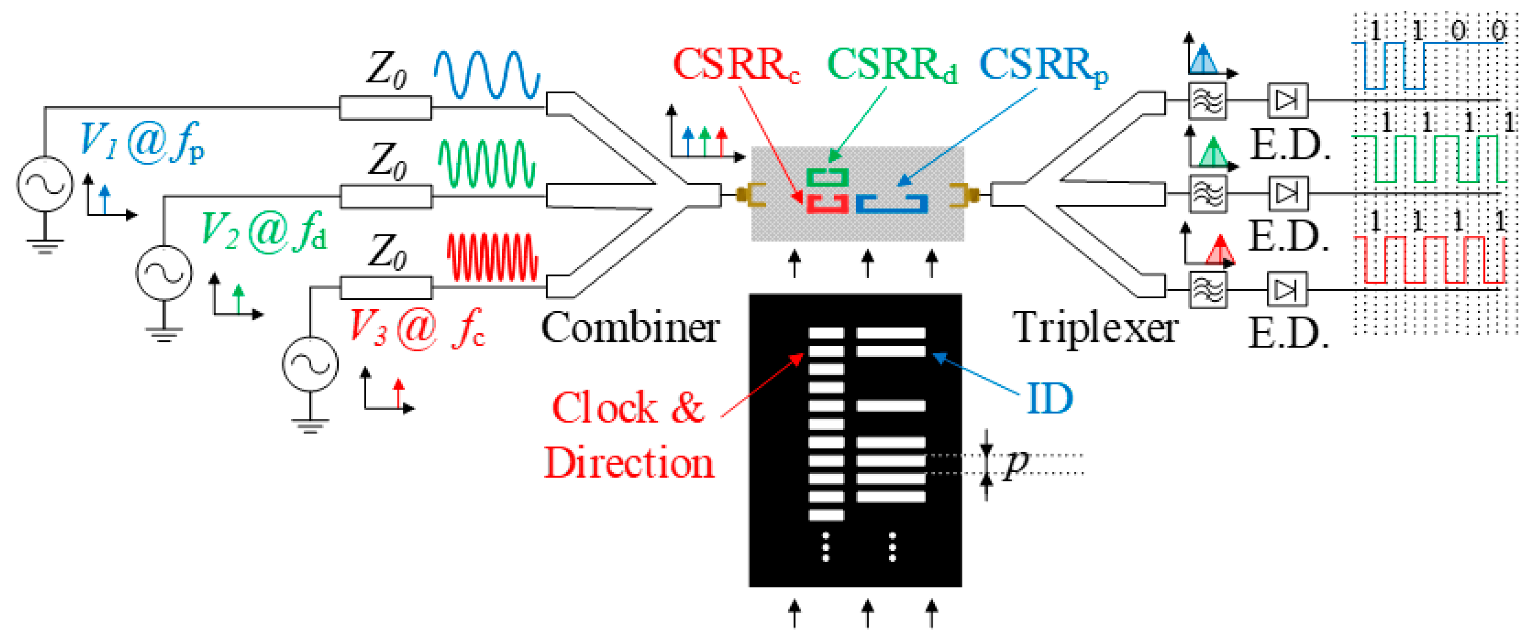
The three harmonic signals necessary for reading purposes are tuned to frequencies fp, fc and fd, as depicted in Figure 4. Such three harmonic signals can be injected simultaneously to the input port of the microstrip line by means of a combiner, and the corresponding AM signals, with different carrier frequencies, separated at the output port by means of a triplexer. Then, the envelope function, containing the relevant information, can be inferred by means of an envelope detector connected to each output port of the triplexer, as done in several reported prototypes of electromagnetic encoders [11,18].
According to the explained working principle, it is clear that the position chain will generate as many dips as apertures in the chain. The instants of time to infer the ID code of that chain are given by the dips generated in the channel corresponding to the clock chain. Also, from the time lapse between adjacent dips in the envelope function generated by the clock chain, the velocity is inferred, provided the period, p, is well known. The system provides the instantaneous velocity, as far as such velocity does not significantly change during time intervals corresponding to the lapse between adjacent dips in the envelope function. Thus, it is also possible to measure the instantaneous acceleration. For the determination of the motion direction, it is not necessary an additional chain. The clock/velocity chain is useful for that purpose, provided the CSRRd is conveniently located with regard to the CSRRc. Particularly, the CSRRd and the CSRRc are located as indicated in Figure 2, so that the apertures of the clock chain first cross one resonator and, immediately, the other one. Thus, from the lead or lag between the corresponding envelope functions, the motion direction can be inferred.
3. Results
The sensitive part of the reader was measured by means of a vector network analyzer (model Agilent N5221A). The behavior of this prototype without any dielectric in the proximity (bare reader) is shown in Figure 3, and it was in good agreement with the electromagnetic simulation. Later, a dielectric PLA slab was placed on top of the reader, and it was moved upwards, thus modifying the air gap, until the behavior was the expected one. The air gap was set to 0.2 mm. This value differs from the nominal air gap considered in the EM simulation (of 0.5 mm). One reason to explain this effect is the EM software, which considers that the substrates are infinite, thereby slightly modifying the effective dielectric constant. Another possible cause can be attributed to the variation of the dielectric constant of the PLA, as explained before, due to fabrication tolerances. In any case, it is important to bear in mind that the higher the air gap, the lower is the dynamic range at the operation frequencies, that is to say that the lower is the difference between the two logic states. On the other hand, if the air gap is reduced, the dynamic range can be improved but, due to the fact that the frequency behavior is shifted down, the frequency notches can affect the vicinity frequency responses (overlap).
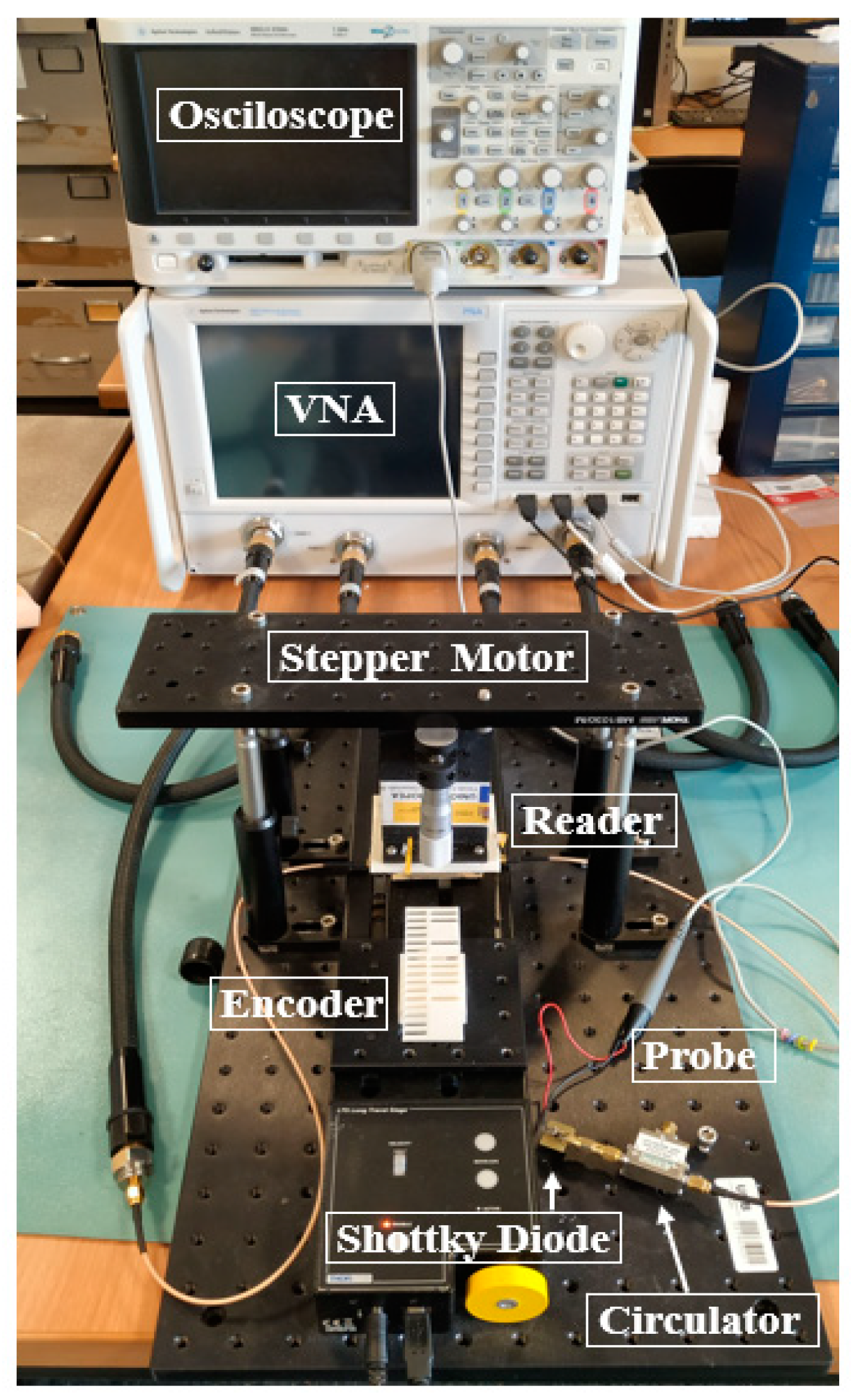
In order to read the encoder of Figure 1 with the reader of Figure 2, using the arrangement of Figure 4, the setup depicted in Figure 5 was used. The displacement of the encoder over the reader was achieved by means of a linear displacement system (model STM 23Q-3AN). It is necessary to generate three harmonic signals (tuned to fp = 4.030 GHz, fc = 4.300 GHz and fd = 4.570 GHz) to synchronous reading the ID code of the encoder, as well as to determine the encoder direction. However, as a proof of concept, instead of injecting simultaneously three signals generated by means of VCOs, the abovementioned vector network analyzer was used to independently generate such signals. As mentioned before, at the output port of the sensitive part of the reader, the signal was AM modulated by the encoder motion. Thus, a Schottky diode (model Avago HSMS- 2860) was used to obtain the envelop function. Since the diode input impedance was different from the output impedance of the sensitive part of the reader, a circulator (model ATM ATc4-8) was added between these devices to prevent undesired reflections. Finally, an oscilloscope (model Agilent MSO-X-3104A) connected to the diode, through the N2795A active probe (with capacitance C = 1 pF and resistance R = 1 MΩ), was used for visualizing the envelope functions (ID code and clock signals).
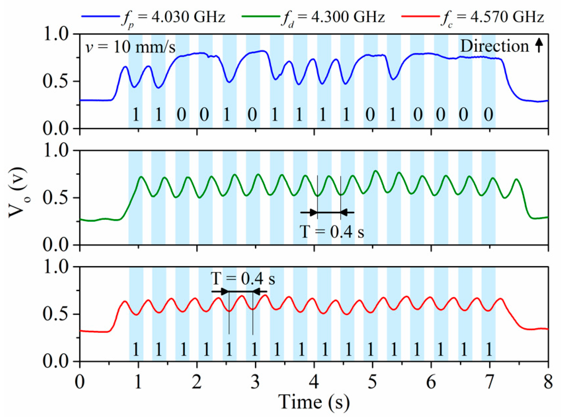
Figure 6 depicts the measured envelope functions inferred from the experimental setup of Figure 6, obtained by displacing the encoder at constant velocity of v = 10 mm/s. As it can be seen, the ID code was correctly read, and the clock signals were shifted, as consequence of the different positions of the resonators CSRRc and CSRRd in the reader. According to these results, the clock chain first crossed the CSRRc and then the CSRRd. Thus, the direction of motion was determined.
This was the first electromagnetic encoder able to provide the ID code synchronously, and able to discriminate the direction of motion, implemented without metallic inclusions. As compared to the encoder reported in [67], the proposed encoder is very robust against friction (eventually caused by unexpected contact between the encoder and the reader, as consequence, e.g., of vibrations), since the inclusions are simple apertures. Thus, these 3D-printed encoders may be of interest as quasi-absolute encoders in motion control applications. Nevertheless, the reported prototype demonstrated that by opening apertures in a 3D-printed material, it was possible to generate an encoder containing an identifying ID code. Thus, with the results of this work, the possibility of generating an identifying tag embedded in a certain fabricated (3D-printed) material or consumer product during fabrication was possible.
4. Conclusions
In this paper, electromagnetic encoders with synchronous reading and motion direction detection capability have been presented. The encoder is implemented by means of chains of apertures made in a host substrate, which can be any dielectric material, even flexible, with a dielectric constant significantly different than the one of vacuum. In this work, 3D-printing techniques were employed due to their versatility and good performance already demonstrated with the implementation of other RFID devices. For that purpose, a prototype 3D-printed electromagnetic encoder with 16 bits has been fabricated in dielectric PLA filament. On the other hand, the sensitive part of the reader detects the presence of the apertures by virtue of the permittivity contrast with the host substrate material (PLA), since the sensitive part of the reader is, indeed, a permittivity sensor. In the reported encoders, the relevant information relative to the ID code, encoder velocity (and acceleration, if encoder motion is non-uniform), and motion direction is contained in the envelope functions of the AM modulated signals generated at the output ports of the corresponding channels. The measured envelope functions are indicative of the functionality of the proposed reader/encoder system. Such systems, based on all-dielectric 3D-printed encoders, can find applications in motion control (where robustness against mechanical friction is a key aspect), chipless-RFID tags (where the encoder can be embedded in the product during 3D-printing fabrication), and other potential applications in industrial scenarios.
Author Contributions
Conceptualization, F.P., C.H., and F.M.; methodology, F.P. and C.H.; design, F.P. and C.H.; experimental validation, F.P. and C.H.; paper writing, F.P., F.M.; general supervision, F.M. All authors have read and agreed to the published version of the manuscript.
Funding
This work was supported by MICINN-Spain (project PID2019-103904RB-I00), by Generalitat de Catalunya (project 2017SGR-1159), by Institució Catalana de Recerca i Estudis Avançats (who awarded Ferran Martín), and by ERDF funds.
Conflicts of Interest
The authors declare no conflict of interest.
References
- Eitel, E. Basics of Rotary Encoders: Overview and New Technologies. Machine Design Magazine, 7 May 2014. [Google Scholar]
- McMillan, G.K.; Considine, D.M. Process Instruments and Controls Handbook, 5th ed.; McGraw Hill: New York, NY, USA, 1999; pp. 5–26. [Google Scholar]
- Li, X.; Qi, J.; Zhang, Q.; Zhang, Y. Bias-tunable dual-mode ultraviolet photodetectors for photoelectric tachometer. Appl. Phys. Lett. 2014, 104, 0411081–0411084. [Google Scholar] [CrossRef]
- Jeong, K.; Park, J.; Yoon, J.S. High-precision encoder using moire fringe and neural network. In Proceedings of the SPIE in Optomechatronic Systems, Boston, MA, USA, 5–6 November 2000; Volume 4190, pp. 1–7. [Google Scholar]
- Petriu, E.M. Reconsidering natural binary encoding for absolute position measurement application. IEEE Trans. Instrum. Meas. 1989, 38, 1014–1016. [Google Scholar] [CrossRef]
- Ueda, T.; Kohsaka, F.; Iino, T.; Kazami, K.; Nakayama, H. Optical absolute encoder using spatial filter. In Proceedings of the SPIE Photomechanics and Speckle Metrology, San Diego, CA, USA, 17–20 August 1987; pp. 217–221. [Google Scholar]
- Herrojo, C.; Mata-Contreras, J.; Paredes, F.; Martín, F. Microwave encoders for chipless RFID and angular velocity sensors based on S-shaped split ring resonators (S-SRRs). IEEE Sens. J. 2017, 17, 4805–4813. [Google Scholar] [CrossRef] [Green Version]
- Mata-Contreras, J.; Herrojo, C.; Martín, F. Application of split ring resonator (SRR) loaded transmission lines to the design of angular displacement and velocity sensors for space applications. IEEE Trans. Microw. Theory Tech. 2017, 65, 4450–4460. [Google Scholar] [CrossRef] [Green Version]
- Herrojo, C.; Mata-Contreras, J.; Paredes, F.; Núñez, A.; Ramon, E.; Martín, F. Near-field chipless-RFID system with erasable/programmable 40-bit tags inkjet printed on paper substrates. IEEE Microw. Wirel. Comp. Lett. 2018, 28, 272–274. [Google Scholar] [CrossRef]
- Mata-Contreras, J.; Herrojo, C.; Martín, F. Detecting the rotation direction in contactless angular velocity sensors implemented with rotors loaded with multiple chains of split ring resonators (SRRs). IEEE Sens. J. 2018, 18, 7055–7065. [Google Scholar] [CrossRef]
- Herrojo, C.; Muela, F.; Mata-Contreras, J.; Paredes, F.; Martín, F. High-density microwave encoders for motion control and near-field chipless-RFID. IEEE Sens. J. 2019, 19, 3673–3682. [Google Scholar] [CrossRef]
- Herrojo, C.; Paredes, F.; Martín, F. Double-stub loaded microstrip line reader for very high data density microwave encoders. IEEE Trans. Microw. Theory Tech. 2019, 67, 3527–3536. [Google Scholar] [CrossRef]
- Havlíček, J.; Herrojo, C.; Paredes, F.; Mata-Contreras, J.; Martín, F. Enhancing the per-unit-length data density in near-field chipless-RFID systems with sequential bit reading. IEEE Ant. Wirel. Prop. Lett. 2019, 18, 89–92. [Google Scholar] [CrossRef]
- Paredes, F.; Herrojo, C.; Escudé, R.; Ramon, E.; Martín, F. High Data Density Near-Field Chipless-RFID Tags with Synchronous Reading. IEEE J. RFID 2020, 4, 517–524. [Google Scholar] [CrossRef]
- Herrojo, C.; Paredes, F.; Martín, F. 3D-printed all-dielectric electromagnetic encoders with synchronous reading for measuring displacements and velocities. Sensors 2020, 20, 4837. [Google Scholar] [CrossRef]
- Herrojo, C.; Paredes, F.; Martín, F. Synchronism and Direction Detection in High-Resolution/High-Density Electromagnetic Encoders. IEEE Sens. J. 2021, 21, 2873–2882. [Google Scholar] [CrossRef]
- Kikuchi, Y.; Nakamura, F.; Wakiwaka, H.; Yamada, H.; Yamamoto, Y. Consideration of magnetization and detection on magnetic rotary encoder using finite element method. IEEE Trans. Magn. 1997, 33, 2159–2162. [Google Scholar] [CrossRef]
- Jeong, S.H.; Rhyu, S.H.; Kwon, B.I.; Kim, B.T. Design of the rotary magnetic position sensor with the sinusoidally magnetized permanent magnet. IEEE Trans. Magn. 2007, 43, 1837–1840. [Google Scholar] [CrossRef]
- Nakano, K.; Takahashi, T.; Kawahito, S. A CMOS smart rotary encoder using magnetic sensor arrays. In Proceedings of the 2nd International Conference on Sensors (Sensors ’03), Toronto, ON, Canada, 22–24 October 2003; pp. 206–209. [Google Scholar]
- Lozanova, S.; Roumenin, C. Angular position device with 2D low-noise Hall microsensor. Sens. Actuators A Phys. 2010, 162, 167–171. [Google Scholar] [CrossRef]
- Lan, T.; Liu, Y.W.; Jin, M.H.; Fan, S.W.; Chen, Z.P.; Liu, H. Study of ultra-miniature giant magneto resistance sensor system based on 3D static magnetic analysis technique. Measurement 2009, 42, 1011–1016. [Google Scholar] [CrossRef]
- Hoang, H.V.; Jeon, J.W. An efficient approach to correct the signals and generate high-resolution quadrature pulses for magnetic encoders. IEEE Trans. Ind. Electron. 2011, 58, 3634–3646. [Google Scholar] [CrossRef]
- Zhang, Z.; Ni, F.; Dong, Y.; Jin, M.; Liu, H. A novel absolute angular position sensor based on electromagnetism. Sens. Actuators A 2013, 194, 196–203. [Google Scholar] [CrossRef]
- Zhang, Z.; Dong, Y.; Ni, F.; Jin, M.; Liu, H. A Method for Measurement of Absolute Angular Position and Application in a Novel Electromagnetic Encoder System. J. Sens. 2015, 2015, 503852. [Google Scholar] [CrossRef]
- Naqui, J.; Martín, F. Application of broadside-coupled split ring resonator (BC-SRR) loaded transmission lines to the design of rotary encoders for space applications. In Proceedings of the IEEE MTT-S International Microwave Symposium Digest (IMS’16), San Francisco, CA, USA, 22–27 May 2016; pp. 286–289. [Google Scholar]
- Naqui, J.; Martín, F. Transmission Lines Loaded with Bisymmetric Resonators and Their Application to Angular Displacement and Velocity Sensors. IEEE Trans. Microw. Theory Tech. 2013, 61, 4700–4713. [Google Scholar] [CrossRef]
- Naqui, J.; Martín, F. Angular displacement and velocity sensors based on electric-LC (ELC) loaded microstrip lines. IEEE Sens. J. 2014, 14, 939–940. [Google Scholar] [CrossRef] [Green Version]
- Naqui, J.; Coromina, J.; Karami-Horestani, A.; Fumeaux, C.; Martín, F. Angular displacement and velocity sensors based on coplanar waveguides (CPWs) loaded with S-shaped split ring resonator (S-SRR). Sensors 2015, 15, 9628–9650. [Google Scholar] [CrossRef] [PubMed] [Green Version]
- Herrojo, C.; Paredes, F.; Mata-Contreras, J.; Martín, F. All-dielectric electromagnetic encoders based on permittivity contrast for displacement/velocity sensors and chipless-RFID tags. In Proceedings of the IEEE MTT-S International Microwave Symposium Digest (IMS’19), Boston, MA, USA, 2–7 June 2019; pp. 295–392. [Google Scholar]
- Herrojo, C.; Paredes, F.; Martín, F. 3D-printed high data-density electromagnetic encoders based on permittivity contrast for motion control and chipless-RFID. IEEE Trans. Microw. Theory Tech. 2020, 68, 1839–1850. [Google Scholar] [CrossRef]
- Paredes, F.; Herrojo, C.; Martin, F. An approach for Synchronous Reading of Near-Field Chipless-RFID Tags. In Proceedings of the 10th IEEE Intern. Conf. RFID Technology and Applications (IEEE RFID-TA 2019), Pisa, Italy, 25–27 September 2019; pp. 192–196. [Google Scholar]
- Paredes, F.; Herrojo, C.; Martín, F. Microwave Encoders with Synchronous Reading and Direction Detection for Motion Control Applications. In Proceedings of the IEEE MTT-S International Microwave Symposium Digest (IMS’20), Los Angeles, CA, USA, 13–17 June 2020; pp. 472–475. [Google Scholar]
- Paredes, F.; Herrojo, C.; Martín, F. Strategies for Synchronously Reading Microwave Encoders and Application to Sensors for Motion Control. In Proceedings of the 5th International Conference on Smart and Sustainable Technologies, Split, Croatia, 1–4 July 2020. [Google Scholar]
- Herrojo, C.; Mata-Contreras, J.; Paredes, F.; Martín, F. Near-Field Chipless RFID Encoders with Sequential Bit Reading and High Data Capacity. In Proceedings of the IEEE MTT-S International Microwave Symposium Digest (IMS’17), Honolulu, HI, USA, 4–9 June 2017; pp. 1564–1567. [Google Scholar]
- Paredes, F.; Herrojo, C.; Martín, F. Chipless-RFID Sensors for Motion Control Applications. In Proceedings of the URSI-GASS 2020, Rome, Italy, 29 August–4 September 2020. [Google Scholar]
- Chamarti, A.; Varahramyan, K. Transmission delay line based ID generation circuit for RFID applications. IEEE Microw. Compon. Lett. 2006, 16, 588–590. [Google Scholar] [CrossRef]
- Vemagiri, J.; Chamarti, A.; Agarwal, M.; Varahramyan, K. Transmission line delay-based radio frequency identification (RFID) tag. Microw. Opt. Technol. Lett. 2007, 49, 1900–1904. [Google Scholar] [CrossRef]
- Schüßler, M.; Damm, C.; Maasch, M.; Jakoby, R. Performance evaluation of left-handed delay lines for RFID backscatter applications. In Proceedings of the IEEE MTT-S International Microwave Symposium Digest, Atlanta, GA, USA, 15–20 June 2008; pp. 177–180. [Google Scholar]
- Preradovic, S.; Karmakar, N.C. Chipless RFID: Bar code of the future. IEEE Microw. Mag. 2010, 11, 87–97. [Google Scholar] [CrossRef]
- Preradovic, S.; Karmakar, N.C. Multiresonator-Based Chipless RFID: Barcode of the Future, 1st ed.; Springer: Cham, Switzerland, 2011. [Google Scholar]
- Jalaly, I.; Robertson, I.D. RF barcodes using multiple frequency bands. In Proceedings of the IEEE MTT-S International Microwave Symposium Digest (IMS’05), Long Beach, CA, USA, 3–9 June 2005; pp. 139–142. [Google Scholar]
- Preradovic, S.; Balbin, I.; Karmakar, N.C.; Swiegers, G.F. Multiresonator-based chipless RFID system for low-cost item tracking. IEEE Trans. Microw. Theory Tech. 2009, 57, 1411–1419. [Google Scholar] [CrossRef] [Green Version]
- Preradovic, S.; Karmakar, N.C. Design of chipless RFID tag for operation on flexible laminates. IEEE Anten. Wirel. Propag. Lett. 2010, 9, 207–210. [Google Scholar] [CrossRef]
- McVay, J.; Hoorfar, A.; Engheta, N. Space-filling curve RFID tags. In Proceedings of the IEEE Radio Wireless Symposium, San Diego, CA, USA, 17–19 October 2006; pp. 199–202. [Google Scholar]
- Jalaly, I.; Robertson, D. Capacitively-tuned split microstrip resonators for RFID barcodes. In Proceedings of the European Microwave Conference, Paris, France, 3–7 October 2005; pp. 4–7. [Google Scholar]
- Jang, H.S.; Lim, W.G.; Oh, K.S.; Moon, S.M.; Yu, J.W. Design of low-cost chipless system using printable chipless tag with electromagnetic code. IEEE Microw. Wirel. Compon. Lett. 2010, 20, 640–642. [Google Scholar] [CrossRef]
- Vena, A.; Perret, E.; Tedjini, S. Chipless RFID tag using hybrid coding technique. IEEE Trans. Microw. Theory Tech. 2011, 59, 3356–3364. [Google Scholar] [CrossRef]
- Herraiz-Martínez, F.J.; Paredes, F.; Zamora, G.; Martín, F.; Bonache, J. Printed magnetoinductive-wave (MIW) delay lines for chipless RFID applications. IEEE Trans. Antennas Propag. 2012, 60, 5075–5082. [Google Scholar] [CrossRef]
- Martinez-Martinez, J.J.; Herraiz-Martinez, F.J.; Galindo-Romera, G. A contactless RFID system based on chipless MIW tags. IEEE Trans. Antennas Propag. 2018, 66, 5064–5071. [Google Scholar] [CrossRef]
- Vena, A.; Perret, E.; Tedjini, S. A fully printable chipless RFID tag with detuning correction technique. IEEE Microw. Wirel. Compon. Lett. 2012, 22, 209–211. [Google Scholar] [CrossRef]
- Vena, A.; Perret, E.; Tedjini, S. Design of compact and auto-compensated single-layer chipless RFID tag. IEEE Trans. Microw. Theory Tech. 2012, 60, 2913–2924. [Google Scholar] [CrossRef]
- Islam, M.A.; Karmakar, N.C. Compact printable chipless RFID systems. IEEE Trans. Microw. Theory Tech. 2015, 63, 3785–3793. [Google Scholar] [CrossRef]
- Islam, M.A.; Yap, Y.; Karmakar, N.; Azad, A.K. Orientation independent compact chipless RFID tag. In Proceedings of the IEEE International Conference RFID-Technology Appilication (RFID-TA), Nice, France, 5–7 November 2012. [Google Scholar]
- Islam, M.A.; Karmakar, N.C. A novel compact printable dual polarized chipless RFID system. IEEE Trans. Microw. Theory Tech. 2012, 60, 2142–2151. [Google Scholar] [CrossRef]
- Islam, M.A.; Karmakar, N.C. Real-world implementation challenges of a novel dual-polarized compact printable chipless RFID tag. IEEE Trans. Microw. Theory Tech. 2015, 63, 4581–4591. [Google Scholar] [CrossRef]
- Rance, O.; Siragusa, R.; Lemaître-Auger, P.; Perret, E. Toward RCS magnitude level coding for chipless RFID. IEEE Trans. Microw. Theory Tech. 2016, 64, 2315–2325. [Google Scholar] [CrossRef]
- Polivka, M.; Havlicek, J.; Svanda, M.; Machac, J. Improvement of RCS response of U-shaped strip-based chipless RFID tags. In Proceedings of the European Microwave Conference (EuMC), Paris, France, 7–10 September 2015. [Google Scholar]
- Havlicek, J.; Svanda, M.; Polivka, M.; Machac, J.; Kracek, J. Chipless RFID tag based on electrically small spiral capacitively loaded dipole. IEEE Antennas Wirel. Propag. Lett. 2017, 16, 3051–3054. [Google Scholar] [CrossRef]
- Forouzandeh, M.; Karmakar, N.C. Chipless RFID tags and sensors: A review on time-domain techniques. Wirel. Power Transf. 2015, 2, 62–77. [Google Scholar] [CrossRef]
- Costa, F.; Genovesi, S.; Monorchio, A. A chipless RFID based on multiresonant high-impedance surfaces. IEEE Trans. Microw. Theory Tech. 2013, 61, 146–152. [Google Scholar] [CrossRef]
- Jimenez-Saez, A.; Schussler, M.; Nickel, M.; Jakoby, R. Hybrid Time-Frequency Modulation Scheme for Chipless Wireless Identification and Sensing. IEEE Sens. J. 2018, 18, 7850–7859. [Google Scholar] [CrossRef]
- Kracek, J.; Svanda, M.; Hoffmann, K. Scalar method for reading of chipless RFID tags based on limited ground plane backed dipole resonator array. IEEE Trans. Microw. Theory Tech. 2019, 67, 4547–4558. [Google Scholar] [CrossRef]
- Svanda, M.; Polivka, M.; Havlicek, J.; Machac, J.; Werner, D.H. Platform tolerant, high encoding capacity dipole array-plate chipless RFID tags. IEEE Access 2019, 7, 138707–138720. [Google Scholar] [CrossRef]
- Svanda, M.; Machac, J.; Polivka, M.; Havlova, S.; Fitl, P.; Vrnata, M. Chipless RFID Tag with Enhanced RCS Used as a Phthalocyanine-Based Solvent Vapors Sensor. IEEE Antennas Wirel. Propag. Lett. 2020, 19, 1556–1560. [Google Scholar] [CrossRef]
- Martín, F.; Herrojo, C.; Mata-Contreras, J.; Paredes, F. Time-Domain Signature Barcodes for Chipless-RFID and Sensing Applications, 1st ed.; Springer: Cham, Switzerland, 2020. [Google Scholar]
- Herrojo, C.; Paredes, F.; Mata-Contreras, J.; Ramon, E.; Núñez, A.; Martín, F. Time-domain signature barcodes: Near-field chipless-RFID systems with high data capacity. IEEE Microw. Mag. 2019, 20, 87–101. [Google Scholar] [CrossRef]
- Herrojo, C.; Paredes, F.; Mata-Contreras, J.; Martín, F. Chipless-RFID: A review and recent developments. Sensors 2019, 19, 3385. [Google Scholar] [CrossRef] [Green Version]
- Herrojo, C.; Moras, M.; Paredes, F.; Núñez, A.; Ramón, E.; Mata-Contreras, J.; Martín, F. Very low-cost 80-bit chipless-RFID tags inkjet printed on ordinary paper. Technologies 2018, 6, 52. [Google Scholar] [CrossRef] [Green Version]
- Herrojo, C.; Mata-Contreras, J.; Paredes, F.; Martín, F. Near-field chipless RFID system with high data capacity for security and authentication applications. IEEE Trans. Microw. Theory Tech. 2017, 65, 5298–5308. [Google Scholar] [CrossRef] [Green Version]
- Sanna, G.; Montisci, G.; Jin, Z.; Fanti, A.; Sanna, G.; Montisci, G.; Jin, Z.; Fanti, A.; Casula, G.A. Design of a Low-Cost Microstrip Directional Coupler with High Coupling for a Motion Detection Sensor. Electronics 2018, 7, 25. [Google Scholar] [CrossRef] [Green Version]
- Baire, M.; Melis, A.; Lodi, M.B.; Tuveri, P.; Dachena, C.; Simone, M.; Fanti, A.; Fumera, G.; Pisanu, T.; Mazzarella, G. A Wireless Sensor Network for Monitoring the Carasau Bread Manufacturing Process. Electronics 2019, 8, 1541. [Google Scholar] [CrossRef] [Green Version]
- Andrade, L.; Figueiredo, J.; Tlemçani, M. A New RFID-Identificaton Strategy Applied to the Marble Extraction Industry. Electronics 2021, 10, 491. [Google Scholar] [CrossRef]
- De Bruijn, N.G. Acknowledgement of Priority to C. Flye Sainte-Marie on the Counting of Circular Arrangements of 2n Zeros and Ones that Show Each N-Letter Word Exactly Once; EUT Report (Technological University Eindhoven): Eindhoven, The Netherlands, 1975; pp. 1–16. [Google Scholar]
- Dichtl, C.; Sippel, P.; Krohns, S. Dielectric Properties of 3D Printed Polylactic Acid. Adv. Mater. Sci. Eng. 2017, 2017, 6913835. [Google Scholar] [CrossRef] [Green Version]
- Huber, E.; Mirzaee, M.; Bjorgaad, J.; Hoyack, M.; Noghanian, S.; Chang, I. Dielectric Properties Measurement of PLA. In Proceedings of the IEEE International Conference on Electro Information Technology (EIT), Grand Forks, ND, USA, 19–21 May 2016; pp. 788–792. [Google Scholar]
- Mitra, D.; Roy, S.; Striker, R.; Burczek, E.; Aqueeb, A.; Wolf, H.; Kabir, K.S.; Ye, S.; Braaten, B.D. Conductive Electrifi and Nonconductive NinjaFlex Filaments based Flexible Microstrip Antenna for Changing Conformal Surface Applications. Electronics 2021, 10, 821. [Google Scholar] [CrossRef]
- Colella, R.; Chietera, F.P.; Montagna, F.; Greco, A.; Catarinucci, L. Customizing 3D-Printing for Electromagnetics to Design Enhanced RFID Antennas. IEEE J. Radio Freq. Identif. 2020, 4, 452–460. [Google Scholar] [CrossRef]
- Colella, R.; Chietera, F.P.; Salmeron, J.F.; Rivadeneyra, A.; Capitán-Vallvey, L.F. Fully 3D-Printed RFID Tags based on Printable Metallic Filament: Performance Comparison with other Fabrication Techniques. In Proceedings of the IEEE-APS Topical Conference on Antennas and Propagation in Wireless Communications (APWC), Granada, Spain, 9–13 September 2019; pp. 253–257. [Google Scholar]
- Colella, R.; Chietera, F.P.; Catarinucci, L. Analysis of FDM and DLP 3D-Printing Technologies to Prototype Electromagnetic Devices for RFID Applications. Sensors 2021, 21, 897. [Google Scholar] [CrossRef]
- Ebrahimi, A.; Withayachumnankul, W.; Al-Sarawi, S.; Abbott, D. High-sensitivity metamaterial-inspired sensor for microfluidic dielectric characterization. IEEE Sens. J. 2014, 14, 1345–1351. [Google Scholar] [CrossRef] [Green Version]
- Boybay, M.S.; Ramahi, O.M. Material characterization using complementary split-ring resonators. IEEE Trans. Instrum. Meas. 2012, 61, 3039–3046. [Google Scholar] [CrossRef]
- Lee, C.S.; Yang, C.L. Complementary split-ring resonators for measuring dielectric constants and loss tangents. IEEE Microw. Wirel. Compon. Lett. 2014, 24, 563–565. [Google Scholar] [CrossRef]
- Yang, C.L.; Lee, C.S.; Chen, K.W.; Chen, K.Z. Noncontact measurement of complex permittivity and thickness by using planar resonators. IEEE Trans. Microw. Theory Tech. 2016, 64, 247–257. [Google Scholar] [CrossRef]
- Su, L.; Mata-Contreras, J.; Vélez, P.; Martín, F. Estimation of the complex permittivity of liquids by means of complementary split ring resonator (CSRR) loaded transmission lines. In Proceedings of the IEEE MTT-S International Microwave Workshop Series on Advanced Materials and Processes (IMWS-AMP 2017), Pavia, Italy, 20–22 September 2017. [Google Scholar]
- Su, L.; Mata-Contreras, J.; Vélez, P.; Fernández-Prieto, A.; Martín, F. Analytical method to estimate the complex permittivity of oil samples. Sensors 2018, 18, 984. [Google Scholar] [CrossRef] [PubMed] [Green Version]
Figure 1.
Photograph of the 3D-printed electromagnetic encoder. The total area of the encoder is 30 × 66 mm2, with the following aperture dimensions: d1 = 11.5 mm; d2 = 15.9 mm, w = 2 mm, s = 2 mm and g = 1.9 mm. The thickness of the encoder is 1.5 mm.
Figure 1.
Photograph of the 3D-printed electromagnetic encoder. The total area of the encoder is 30 × 66 mm2, with the following aperture dimensions: d1 = 11.5 mm; d2 = 15.9 mm, w = 2 mm, s = 2 mm and g = 1.9 mm. The thickness of the encoder is 1.5 mm.

Figure 2.
Photograph of the top (a) and bottom (b) side of the reader. The reader was implemented on the Rogers RO4003C substrate with thickness h = 0.81 mm, dielectric constant εr = 3.38 and loss tangent tanδ = 0.0022. Dimensions are: l1 = 26.6 mm; l2 = 3.8 mm, l3 = 10 mm, w1 = 6.4 mm, w2 = 1.9 mm, lc = ld = 10.5 mm; lp = 14.5 mm, wr = 2.9 mm. CSRR slots width is c = 0.5 mm, and ring splits are sd = 0.4 mm, sc = 1.6 mm and sp = 6.2 mm.

Figure 3.
Electromagnetic (EM) simulation and measured frequency response of the bare reader, and the reader loaded with PLA at certain distances (air gap). The EM was obtained by means of the Keysight Momentum software.
Figure 3.
Electromagnetic (EM) simulation and measured frequency response of the bare reader, and the reader loaded with PLA at certain distances (air gap). The EM was obtained by means of the Keysight Momentum software.

Figure 4.
Schematic of the proposed reader/encoder system, based on all-dielectric encoders, with synchronous reading and motion direction detection capability.
Figure 4.
Schematic of the proposed reader/encoder system, based on all-dielectric encoders, with synchronous reading and motion direction detection capability.

Figure 5.
Photograph of the experimental setup.


Publisher’s Note: MDPI stays neutral with regard to jurisdictional claims in published maps and institutional affiliations. |
© 2021 by the authors. Licensee MDPI, Basel, Switzerland. This article is an open access article distributed under the terms and conditions of the Creative Commons Attribution (CC BY) license (https://creativecommons.org/licenses/by/4.0/).
Share and Cite
MDPI and ACS Style
Paredes, F.; Herrojo, C.; Martín, F. 3D-Printed Quasi-Absolute Electromagnetic Encoders for Chipless-RFID and Motion Control Applications. Electronics 2021, 10, 1154. https://doi.org/10.3390/electronics10101154
AMA Style
Paredes F, Herrojo C, Martín F. 3D-Printed Quasi-Absolute Electromagnetic Encoders for Chipless-RFID and Motion Control Applications. Electronics. 2021; 10(10):1154. https://doi.org/10.3390/electronics10101154
Chicago/Turabian StyleParedes, Ferran, Cristian Herrojo, and Ferran Martín. 2021. "3D-Printed Quasi-Absolute Electromagnetic Encoders for Chipless-RFID and Motion Control Applications" Electronics 10, no. 10: 1154. https://doi.org/10.3390/electronics10101154
Note that from the first issue of 2016, this journal uses article numbers instead of page numbers. See further details here.