
Design and Passive Training Control of Elbow Rehabilitation Robot

1
College of Mechanical and Electrical Engineering, China Jiliang University, Hangzhou 310018, China
2
Zhejiang Guozi Robotics Co., Ltd., Hangzhou 311400, China
*
Author to whom correspondence should be addressed.
Electronics 2021, 10(10), 1147; https://doi.org/10.3390/electronics10101147
Submission received: 6 April 2021
/
Revised: 29 April 2021
/
Accepted: 6 May 2021
/
Published: 12 May 2021
(This article belongs to the Section Systems & Control Engineering)
Abstract
:In this paper, a rehabilitation robot driven by multifilament muscles is designed based on the rehabilitation robot motion model and a system elbow joint model. The passive training mode of rehabilitation robots were researched, and active disturbance rejection control (ADRC) leveraged to improve the tracking angle of robot joints. In the no-load motion simulation of rehabilitation robots, disturbances are added to the control variables to complete the ADRC and Proportional Integral Differential (PID) position control simulation. The simulation results indicate that the auto disturbance rejection control can quickly keep up the expected signal without overshoot, solve the contradiction between the system rapidity and overshoot. Moreover, it can better suppress the interference even if the external load changes. The upper limbs of the human body are used as the load on the robot body to complete the simulation of ADRC and PID position control objects of different weights. Finally, a passive rehabilitation training experiment was conducted to verify the safety of the rehabilitation robot, the rationality, comfort, and robustness of the mechanism design, and the effectiveness and feasibility of the ADRC.
1. Introduction
With the rapid development of medical technology, many robots can provide rehabilitation training for affected limbs, like a novel three-degree-of-freedom (DOF) pendulum-like cable-driven robot [1], a new adjustable robotic exoskeleton called MEDARM for motor rehabilitation of the shoulder complex [2]. According to the purpose of exoskeleton robot, systems can be divided into power assistance types that directly give power to human joints and power augmentation types that augment the power of the wearer [3]. In order to lessen the burden of muscle during the training experiences, it is important to supply support for patients [4,5]. A sliding mode controller combined with a nonlinear disturbance observer is proposed [6] to control cable-driven robot in the presence of disturbances. Ref. [7] investigates the PID control of exoskeleton robot arm used for robot-assisted rehabilitation with its embedded harmonic drive transmission (HDT) and Elmo driver. The research of rehabilitation robots can improve the living conditions of the elderly, patients with cerebrovascular diseases, and athletes, reduce the burden of rehabilitation doctors, and make great contributions to medical rehabilitation in China.
The pneumatic muscle proclaims the benefits of a simple and safe structure, good flexibility and portability [8,9,10], high power-to-weight ratio, low cost, pollution-free, and resemblance to human muscle characteristics. The new pneumatic robot has the characteristics of more realistic, portable, and flexible, but the compressibility of air leads to unstable control of the system. Considered comprehensively, the advantages of the pneumatic system outweigh its disadvantages. Therefore, it is the best choice to use pneumatic actuators on rehabilitation robots that need to ensure safety. Rupert (robot-assisted upper extremity repetitive therapy) is a 4-DOF exoskeleton type upper limb assisted robot [11,12,13] designed by Arizona State University. Rupert uses pneumatic muscles as actuators to realize 4-DOF movements of the shoulder, elbow, and wrist [11], which can help patients to carry out some simple movements in daily life. Based on a pneumatic system and combining cable drives, the University of Jordan in Germany designed a 4-DOF robot with an exoskeleton structure of upper limbs [14]. There excite a series of cable-driven systems driven by pneumatic muscles on the back of the prototype. The robot aims to improve the strength of the human upper body, and its applications range from the rehabilitation of stroke patients to weight-bearing work of workers and soldiers. Huazhong University of Science and Technology has developed a 5-DOF upper limb rehabilitation robot driven by pneumatic muscle featured by wear ability, flexibility, and safety [15,16], which can realize the daily movement of the shoulder, elbow, palmar joint, and interphalangeal joint. At the same time, the pneumatic torsion-spring and pneumatic tension-spring drivers are designed to realize the two-way movement of rehabilitation robot joint, which can be used to the arm or hand rehabilitation training simultaneously or separately as needed. A fine diameter pneumatic tube with an outer diameter of 1.8 mm has been developed by selecting a rubber tube with suitable thickness [17]. Shuichi Wakimoto in [18] has made into pneumatic artificial muscle bundles by the fine diameter McKibben pneumatic artificial muscles with the outer diameter being 2.5 mm. Compared with the ordinary McKibben pneumatic muscle with the same outer diameter, the contraction rate is large, and the output force is low, but the safety and robustness of the system can be increased.
Motivated by the results afore mentioned, we firstly analyze the structure of the human upper limb and the movement mode of the elbow joint, the design of the prototype of the elbow rehabilitation robot, and the establishment of the joint model of the robot. Secondly, if the nonlinear terms or external unknown disturbances exist in the dynamic systems, the performance controlled by the traditional PID may be bad. This paper uses the Auto-Disturbance Rejection Control algorithm to analyze the internal and external disturbances in the rehabilitation process [19,20,21,22], and the tracking differentiator, the extended state observer, and the error feedback controller are designed according to the disturbance sources. The simulation results are compared with the ordinary PID control to verify the effect of the auto disturbance rejection control algorithm on disturbance suppression. The scientific exploration involved in the research will also provide basic theoretical and technical support to the integration of mechanics, control, and medicine and the development of other related disciplines.
Our contribution to the passive training control of the elbow rehabilitation robot is that we design a fine McKibben pneumatic muscle bundle and four-bar linkage structure. The designed four-bar linkage structure is similar to human joints, which increase the rotation space and load capacity of the elbow joint. The ADRC algorithm improves the tracking angle of the elbow joint rehabilitation robot.
2. Design of Rehabilitation Robot Prototype
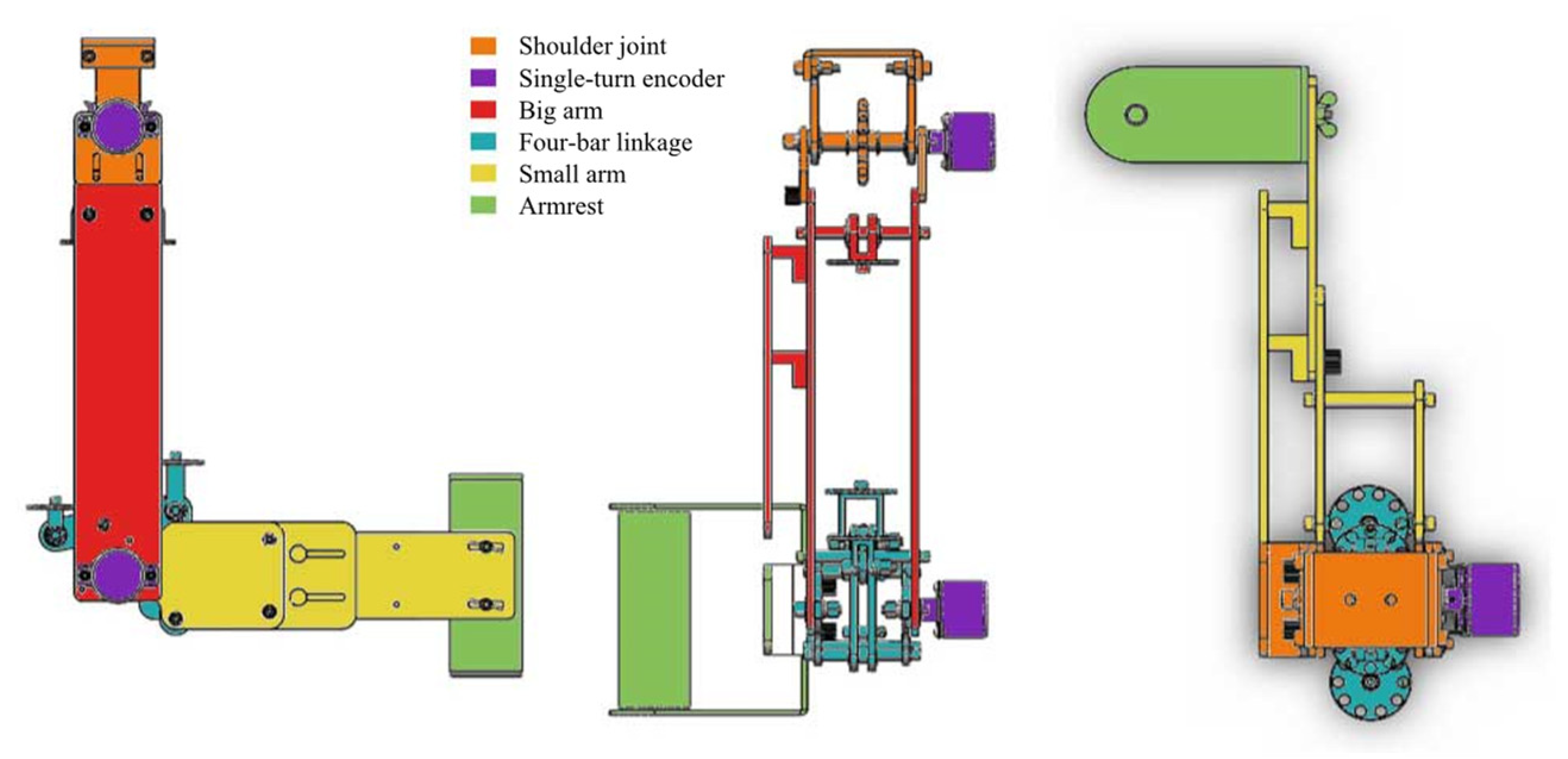
The prototype design should satisfy the convenience and adjustability of the rehabilitation robot, as well as the safety of the rehabilitation process. Therefore, according to the Chinese national standard GB1000-1988 Chinese Adult Body Size, the adjustable range of the robot upper arm length is 270 to 310 mm; the adjustable range of the forearm length is 210 to 240 mm; the adjustable range of the palm-to-wrist-joint length is 55 to 70 mm. The three views of the 3D virtual prototype completed in SolidWorks are shown in Figure 1.
On the upper arm part, there is a rail slot deployed under the top plate which is connected to the base plate through knurled bolts, and the length of the upper arm can be adjusted by sliding along the rail slot. Similarly, the rail slot deployed under the forearm plate is used for adjusting the length of the forearm. The handle at the end of the rehabilitation robot is used to fix the patient’s hand position. At the same time, the bandage-protectors in the middle of the forearm and upper arm parts are used to make the patient’s joint axis coincide with the joint axis of the robot, to ensure the consistency of these two movements.
3. Elbow Rehabilitation Robot Modeling
3.1. Kinematic Model
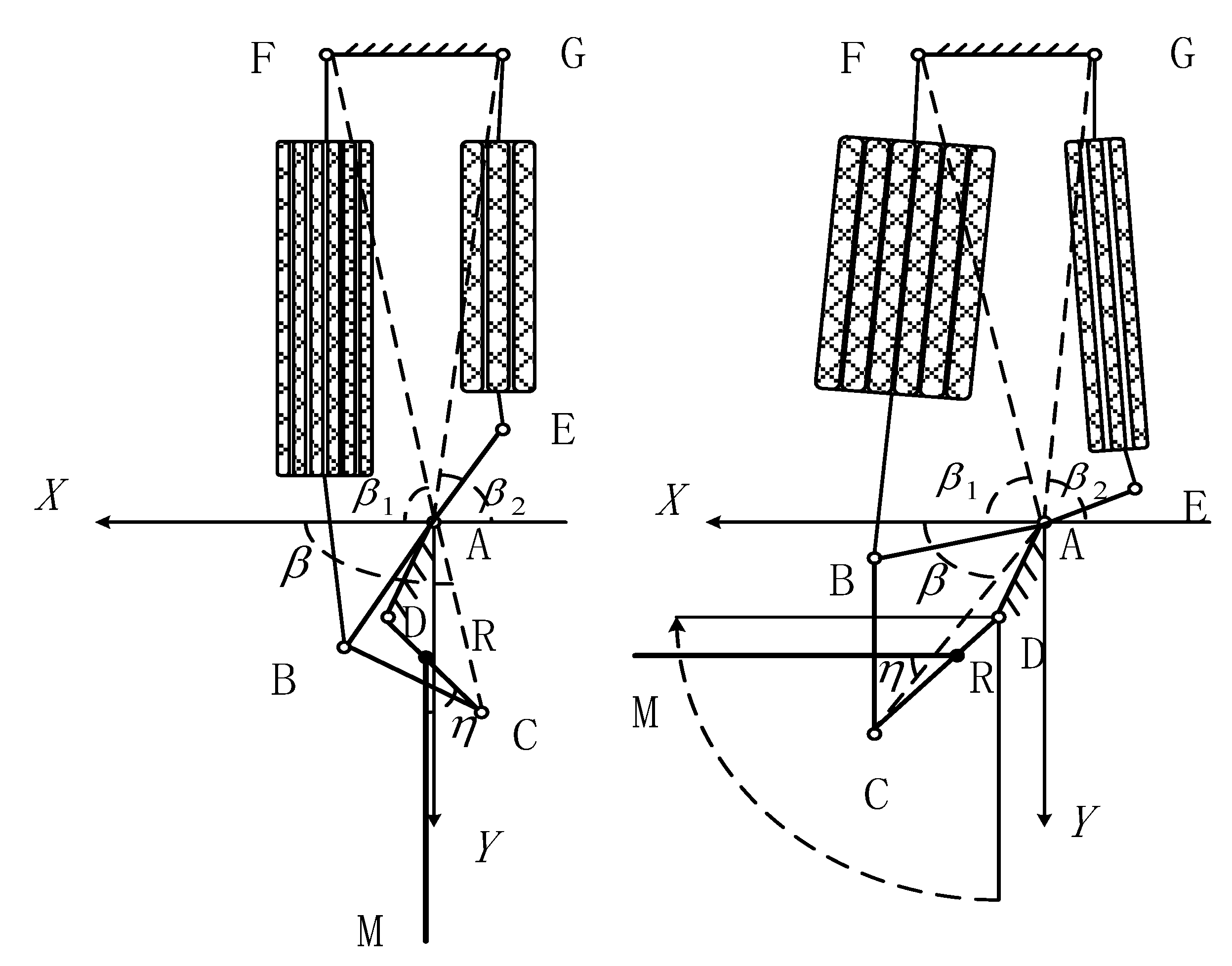
The four-link elbow joint is simplified as the schematic diagram shown in Figure 2, and the pneumatic muscle is installed in the antagonistic method. In order to facilitate the design process and obtain the kinematics relationship of the elbow rehabilitation robot, part of the dimension data is directly obtained from the three-dimensional drawing.
The points A~E in the figure represent the hinges A~E respectively, and , , , , and are the lengths of four-links AB, BC, CD, DA, and AE. The left side is the contraction side pneumatic muscle, and the right side is the extension side pneumatic muscle. Points B and F are the connection points of the contraction side pneumatic muscle; is the length between points B and F. Points E and G are the connection points of the extension side pneumatic muscle; is the length between points E and G. Taking point A as the origin, the direction passing through point A as well as parallel to FG is the x-axis; the direction perpendicular to FG is the y-axis. The coordinate system is established as shown in the figure. The angles from AB, BC, CD, DA to the positive direction of the X-axis are , , , and , respectively, while the angle between forearm RM and positive direction of Y-axis is the rotation angle of elbow joint, the angle between RM and the positive direction of the X-axis RM is ; the angle between forearm RM and Linkage CD is . Therefore, . The angle between AC and the positive direction of the X-axis is ; the angle between AF and the positive direction of the X-axis is ; the angle between AG and negative direction of X-axis is . According to the three-dimensional diagram of the four-link elbow joint mechanism, it is known that: , , , , , , , .
The coordinates of point C can be expressed by and
In , the distance from A to C can be expressed as follows according to the law of cosines
In , the angle between linkage AB and AC according to the law of cosines
The angle between AC and positive direction of X-axis
where xc is the abscissa of C in the x-y coordinate system and is given by Equation (2).
The angle between AB and positive direction of X-axis, where is obtained in Equation (3).
In , lBF is given by the law of cosines as follow
In the equations, is the length of the pneumatic muscle on the contracting side and is the contraction of the pneumatic muscle on the contracting side.
In , is given by the law of cosines as follow
In the equations, is the length of the pneumatic muscle on the extension side and is the contraction of the pneumatic muscle on the extension side.
The functional relation between the contraction of the pneumatic muscle on the contraction side, the contraction on the extension side, and the rotation angles of the elbow joint are obtained as follows.
3.2. Joint Model
The elbow rehabilitation robot system designed in this paper consists of a controller, compressor, proportional valve, and elbow rehabilitation robot. The controller transmits the control signal to the proportional valve, which controls the opening of the proportional valve to inflate the pneumatic muscle and drives the robot to realize rehabilitation movement. Then, the absolute encoder measures the rotation angle of the joint, and feeds the measured value back to the controller, forming a closed-loop control of the system.
The control signal generated by the system is used to control the opening of the proportional valve. The relationship between the control quantity and the output pressure of the proportional valve is as follows:
In the equations, is the initial voltage, is the proportional coefficient, is the voltage coefficient, is the initial pressure of the pneumatic muscle, is the air pressure variation of the pneumatic muscle, and are the pressure values of the two pneumatic muscles.
The experimental fitting model method proposed by Pujana-Arrese et al. is used to obtain the static mathematical model of the pneumatic muscle bundle [23]. The relationship between the output force of pneumatic muscle and its internal pressure is as follows
In the equations, is the contraction force of the pneumatic muscle; is the contraction value of the pneumatic muscle.
According to the dynamic model of elbow rehabilitation robot, the following equation can be obtained
In the equation, represents the moment of inertia of the pneumatic muscle joint; represents the rotation angle of the pneumatic muscle joint; represents the damping coefficient of the pneumatic muscle joint system; represents the uncertainties, including the external disturbance and unmodeled dynamics of the pneumatic muscle system; represents the radius of the pneumatic muscle joint.
By substituting Equations (10)–(12) into Equation (13), the elbow rehabilitation robot model is obtained as follows:
In the equations, , , .
In order to facilitate the design of the controller, it is necessary to express the system model in state equations. Therefore, the selected state , . The state equations of elbow rehabilitation robot are as follows:
In the equations, represents the nonlinear uncertainty in the elbow rehabilitation robot system and is an adjustable parameter.
4. Passive Training Control Algorithms for Elbow Rehabilitation Robot
4.1. Disturbance Sources in Rehabilitation Process
The elbow rehabilitation robot designed in this paper uses the pneumatic muscle as the actuator. Due to the structure of the pneumatic actuator itself, the pneumatic muscle has the characteristics of nonlinearity and time-varying, which leads to certain errors in the joint trajectory tracking control based on the model, which affects the elbow trajectory tracking control effect, and further affects the rehabilitation effect of patients and even results in a more serious consequence: causing the second injury of the patient. In the process of rehabilitation, there will be disturbance and interference from the internal or external environment of the system: when the elbow rehabilitation robot does not drive any load, the disturbance is mainly the nonlinear and uncertain factors of the system. When the elbow rehabilitation robot drives the patient’s arm to carry out passive elbow training, and the upper limb is the external load on the robot, the load varies with the patient’s physical condition. Therefore, the control system should have the ability to ensure robustness and safety in the rehabilitation process.
4.2. Active Disturbance Rejection Control of Elbow Rehabilitation Robot
Active disturbance rejection control (ADRC) is composed of three parts: tracking differentiator (TD), extended state observer (ESO), and error state feedback law. The tracking differentiator is responsible for arranging the transition process, obtaining the smooth input signal and the differential signal of the input signal, which not only realizes rapid control but also eliminates the overshoot of the system and suppresses the noise amplification. The extended state observer is used to eliminate the effects the unknown part of the internal model and the external changes have on the control object. By expanding a state quantity to track the total disturbance to the system, it is used to estimate the external unknown disturbance and the unmodeled part of the control object, becoming an integral series control object. Finally, the control strategy of the control object is set by the error state feedback controller, including linear combination and nonlinear combination. By adding the compensation term of “total disturbance” to the error state feedback controller, the influence of “ total disturbance” on the steady-state error of the system is eliminated, and the feedback efficiency, system stability, and robustness are significantly improved.
In this paper, a second-order nonlinear tracking differentiator is used to arrange the transition process, the expression of TD is:
In the equations, represents the desired rehabilitation trajectory signal of the elbow robot; is the smooth tracking signal obtained through TD; is the differential signal of ; is the velocity factor of TD; is the filtering factor of TD; represents the step length. is the fastest control integration function of discrete system, the expressions are as follows [24].
In the tracking differentiator, the speed factor r can effectively change the speed and smoothness of the transition signal. If r is small, the tracking signal is smooth. If r is large, the output of TD is closer to the expected input, but edges and corners may appear. The size of r will depend on the bearing capacity of the controlled object and the available control capacity, which express as , where A is the given amplitude and T is the set transition time.
A linear extended state observer is used to observe and estimate the nonlinear and time-varying disturbances in the rehabilitation robot system. Considering the elbow rehabilitation robot joint model (15), the nonlinear uncertainties in the model , i.e., the total disturbance of the system are expanded into a new state variable , and suppose . Therefore, the state space equations of the expanded elbow rehabilitation robot system are as follows:
The moment of inertia in the elbow rehabilitation robot model actuated by pneumatic muscle changes with the weight of the patients- changing of the load, which enhances the nonlinearity and uncertainty of the system [25]. Therefore, not only the internal nonlinearity of the system but also the influence of the external load change on the system should be considered. A linear extended state observer is designed for Equation (18), and the ESO structural expressions are as follows [24]:
In the equations, represents the error between the observed value of the actual system output and the actual system output state ; the output state , and of the extended state observer (19) represent the observed values of the states , and the total disturbance state in the system (18) respectively; , and represent the three adjustable gains of the observer respectively.
When the appropriate parameters are selected, the state variable of the state observer can track the state variable of the original system well [24]. Although we don’t use the derivative of the nonlinear term in the state observer, it works during operation.
In order to ensure that the actual rehabilitation trajectory of the elbow rehabilitation robot can track the desired rehabilitation trajectory quickly and accurately, this paper designs an error state feedback controller based on a tracking differentiator and extended state observer output. Error states are represented as follows:
The error feedback controller based on error states and is designed as follows:
In the equations: and are the adjustable gains of the error feedback controller; is the adjustable parameter; the form of nonlinear functions and are shown in Equation (22); is the estimation of nonlinear uncertainty in elbow rehabilitation robot system by ESO.
In the equations, is a minimal positive number which represents the length of the linear interval of a nonlinear function; is the power of the feedback.
4.3. Simulation of Passive Training Control
In the simulation system, the rehabilitation trajectory of the elbow rehabilitation robot is taken as the control object. In the paper, we mainly use the MATLAB R2016a, and the Simulink module. In order to verify the anti-interference ability to different loads, 50 kg and 80 kg simulation object arms are loaded into the simulation system as different loads to carry out joint rehabilitation trajectory control simulation. Firstly, the step signal with the amplitude of 40° is used as the joint rehabilitation trajectory of the elbow rehabilitation robot actuated by the pneumatic muscle for control simulation. The parameters of each part of the active disturbance rejection controller in the simulation process are shown in Table 1, and the simulation results are shown in Figure 3. Compared with the traditional PID control method, the two groups of PID control parameters are shown in Table 2, and the PID control simulation results are shown in Figure 4.
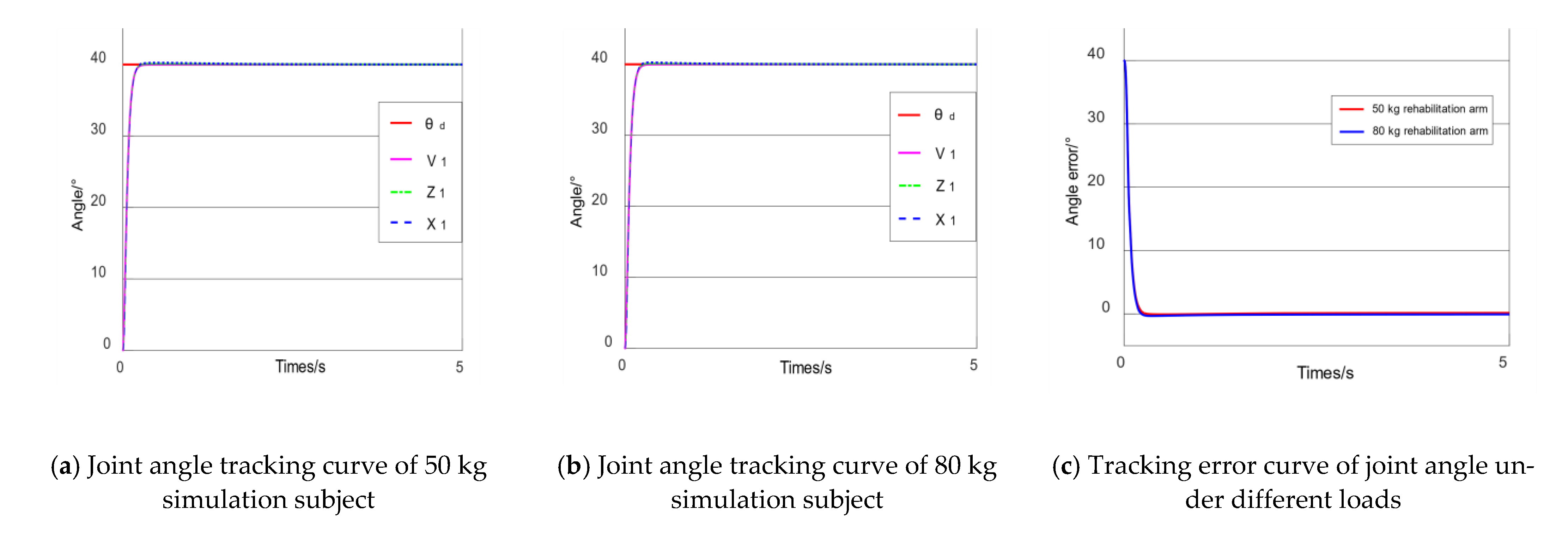
As shown in Figure 3a,b, with the same set of control parameters and various external load, the ADRC algorithm can arrange the transition process for the desired step signal through the tracking differentiator, so as to smooth the abrupt part of the input signal and obtain the smooth tracking signal , which avoids overshoot in the actual simulation output curve . The rise time is 0.305 s and 0.313 s respectively; the overshoot is 0.5% and 0.75% respectively, and they both keep up the desired signal in about 1.1 s, and the final steady-state errors are about 0.15°, as shown in Figure 3c.
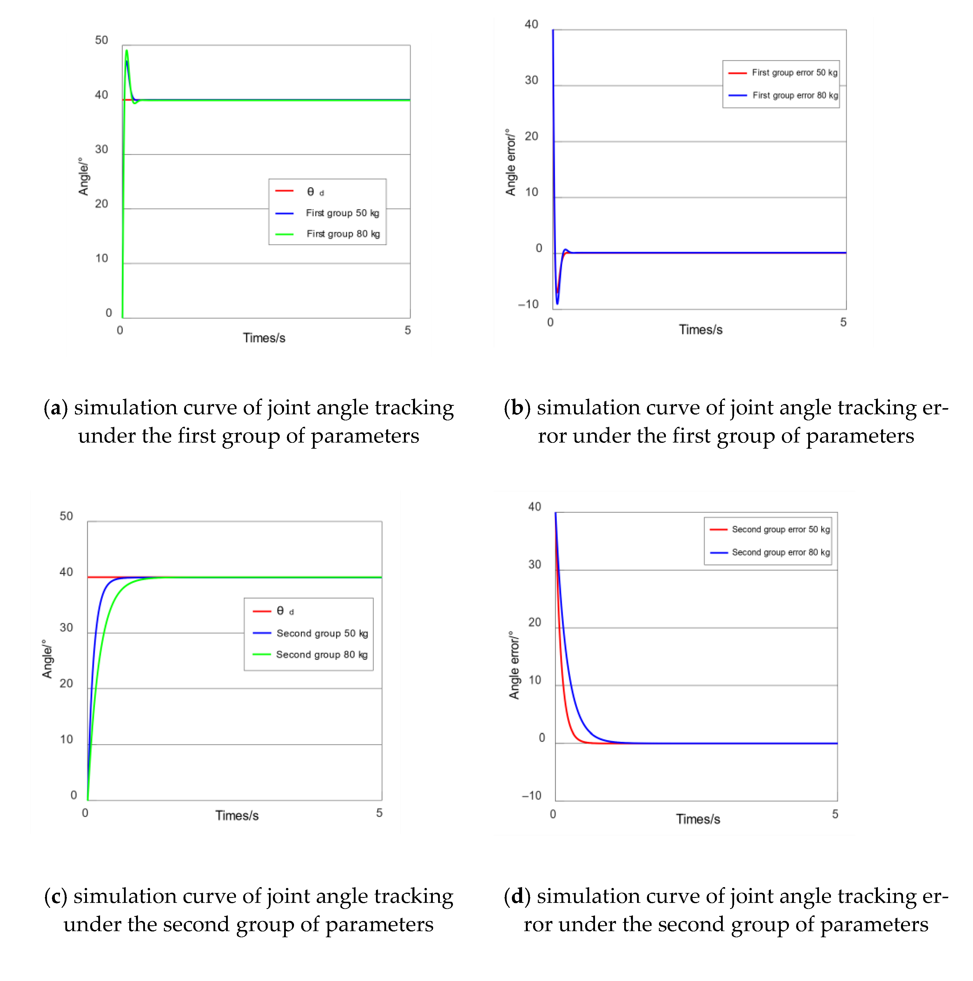
As shown in Figure 4a: in the first group of control parameters, no matter what the load is, the actual simulation output curve shows obvious overshoot; the overshoot is 17.7% and 23% respectively: the heavier weight causes a larger overshoot. The rise time is 0.3 s and 0.31 s respectively. The expected signal is kept up at 1.2 s and 1.4 s respectively: the heavier weight causes longer required time to keep up the expected signal. With the second group of control parameters, the overshoot of the output curve is suppressed, but the time required to keep up the desired signal increases to 2.3 s and 3.5 s: the heavier weight causes slower response speed. It can be concluded that there is a contradiction between rapidity and overshoot in the PID control method. Comparing the simulation results of Figure 3 and Figure 4, the control algorithm designed in this section can achieve a good deflection angle tracking without adjusting the control parameters when the external load changes and the response speed is faster. It solves the contradiction between system rapidity and overshoot. The tracking error does not change significantly, and the disturbance suppression effect is better.
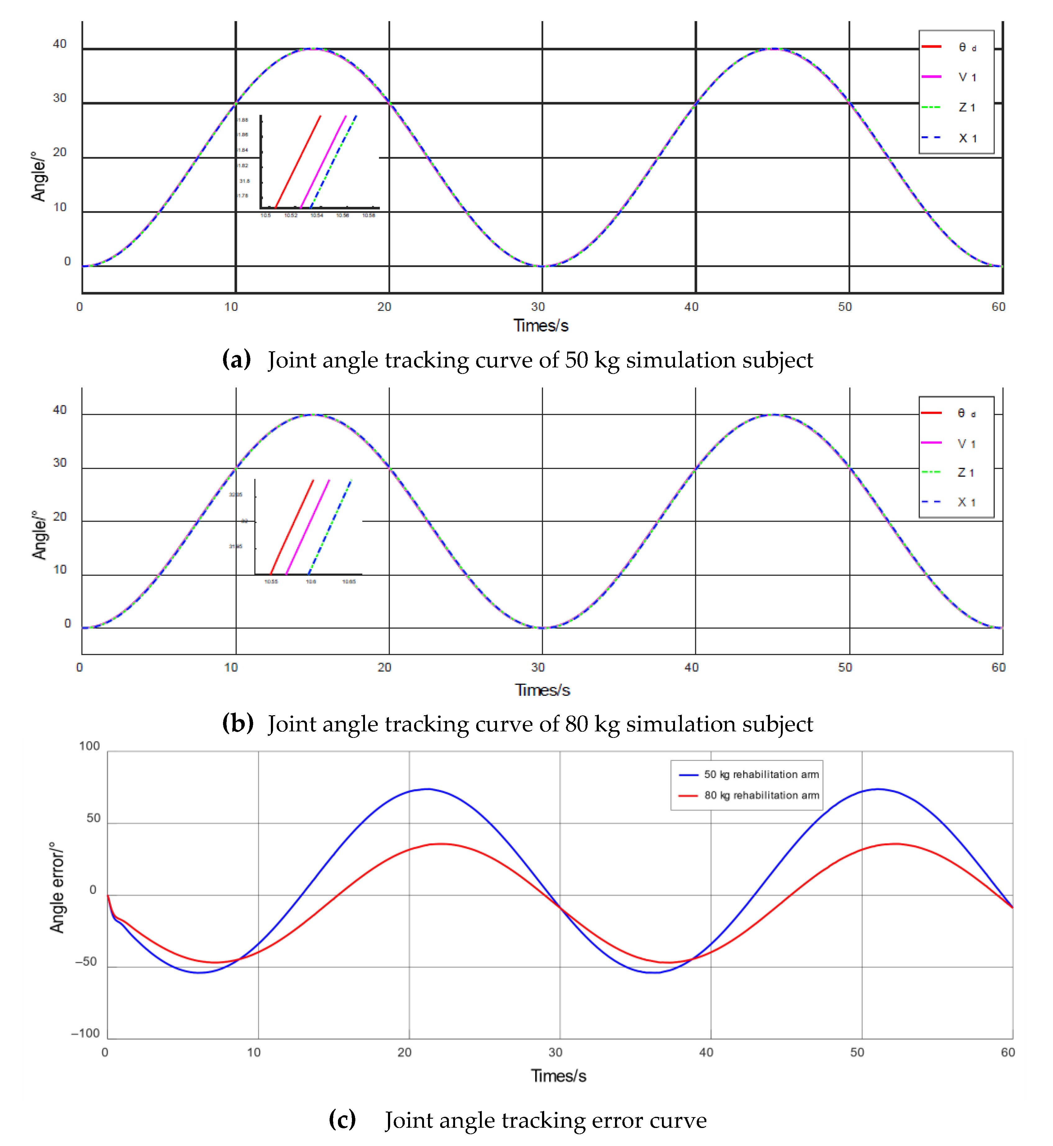
In order to verify that the designed active disturbance rejection control algorithm has a good tracking control effect on different expected signals, sinusoidal signal with equal amplitude and equal period as joint rehabilitation trajectory for control simulation is inputted. The parameters of ADRC in the simulation process are shown in Table 3, and the simulation results are shown in Figure 5 and Figure 6.
According to ergonomics [26], the relationship between adult palm, forearm, upper arm, and body weight is shown in Equation (23).
In the equations, , , represent the weight of human palm, forearm, upper arm, and body weight respectively.
Figure 5a,b show the simulation curves when the weight of the load is 50 kg and 80 kg respectively. represents the given sine signal of 0–40° and the tracking signal obtained by tracking differentiator; represents the tracking signal obtained by through tracking differentiator, and it is the expected target of the system; is the actual output results based on the active disturbance rejection control system; represents the observed value of obtained by the extended state observer. In the case of not adjusting the parameters of the controller, regardless of the load quality, , and can all track quickly and accurately.
As shown in Figure 5c, when the load is 50 kg and 80 kg respectively, the errors are within ±0.25°, which indicates that the robustness of passive training is ensured and the effect of passive rehabilitation is guaranteed.
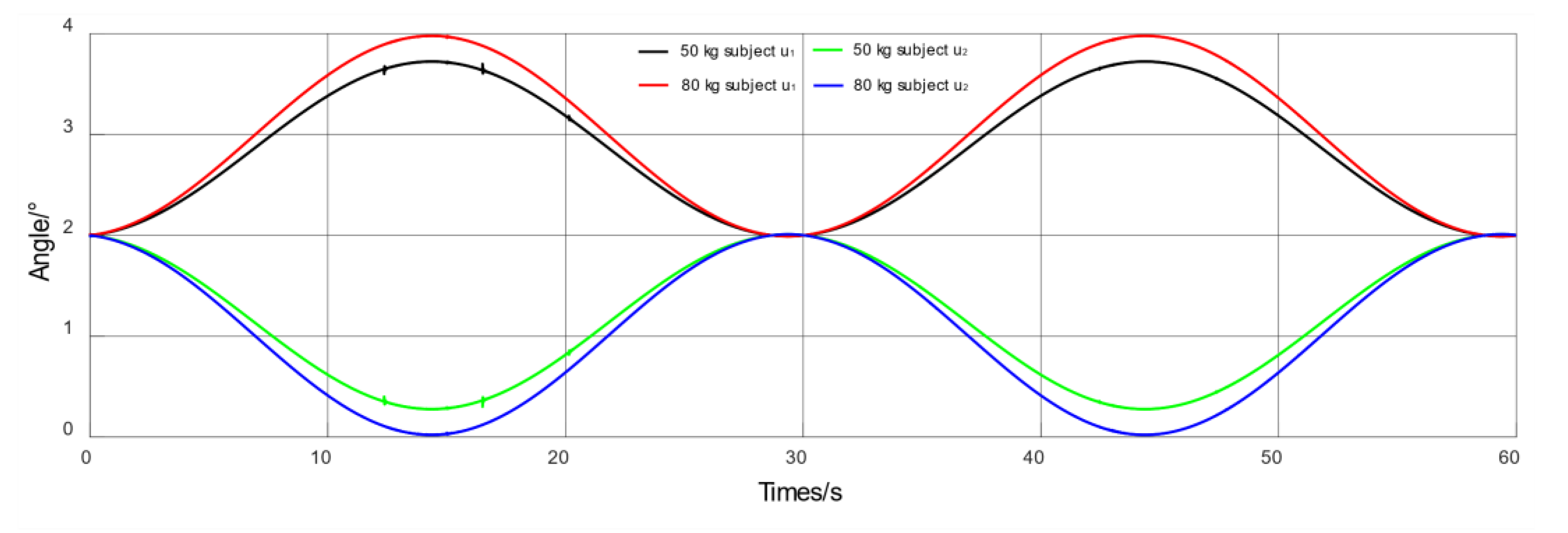
As shown in Figure 6, when the weight of the load is 50 kg and 80 kg respectively, the variation trend of the control voltage of the pressure regulating proportional valve is the same as it without load: when the elbow is bent, the voltage value of the contraction side increases, and the voltage value of the extension side decreases. When the elbow is stretched, the voltage value of the contraction side decreases and the voltage value of the extension side increases. The voltage and change with equal amplitude at the initial voltage . At the same time, with the increase of the load mass, the muscle needs to provide greater contraction force to drive the load movement, the input pressure value increases, and the control voltage increases accordingly.
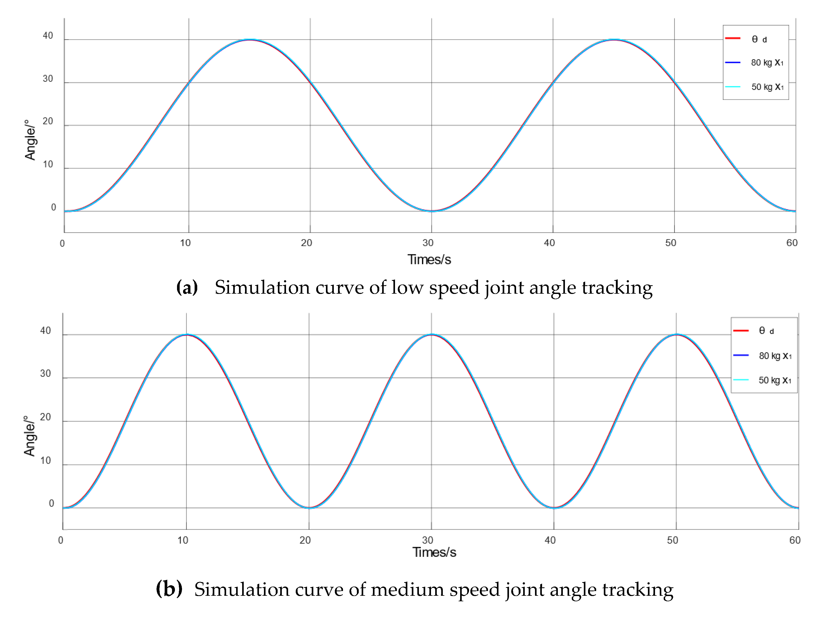
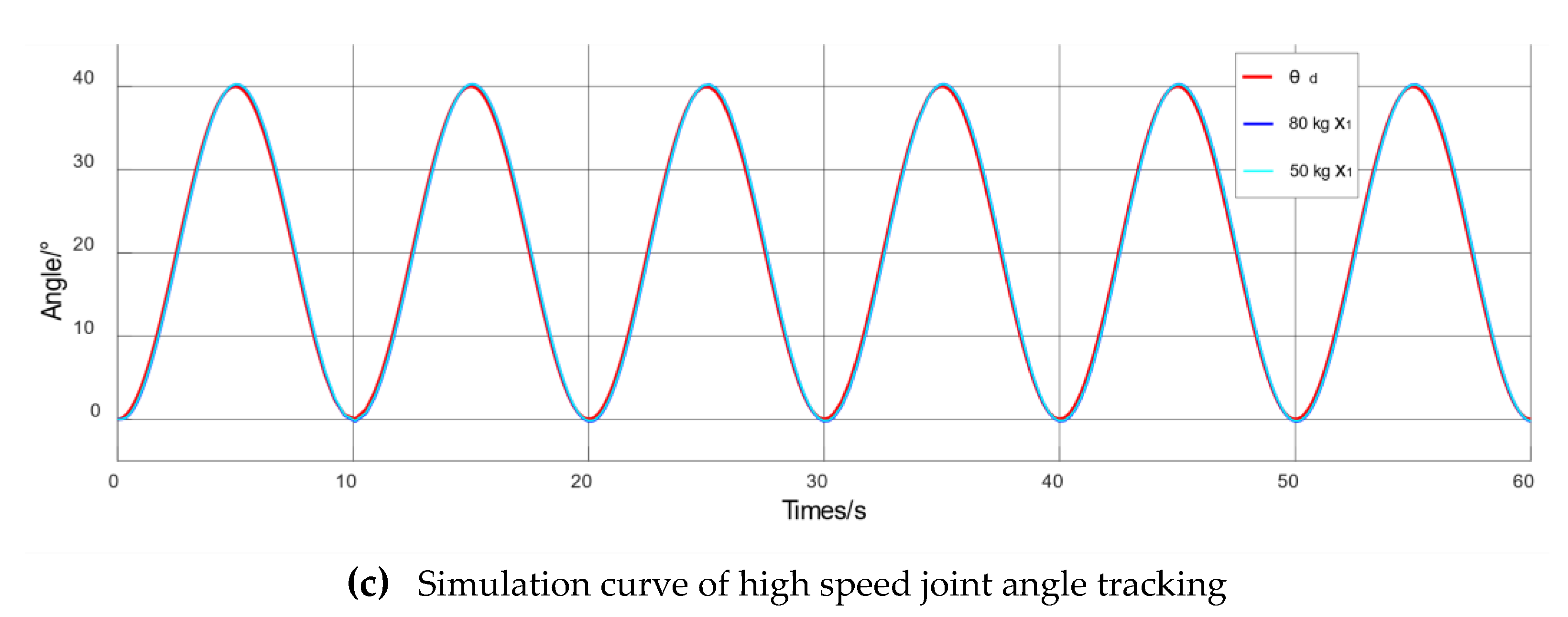
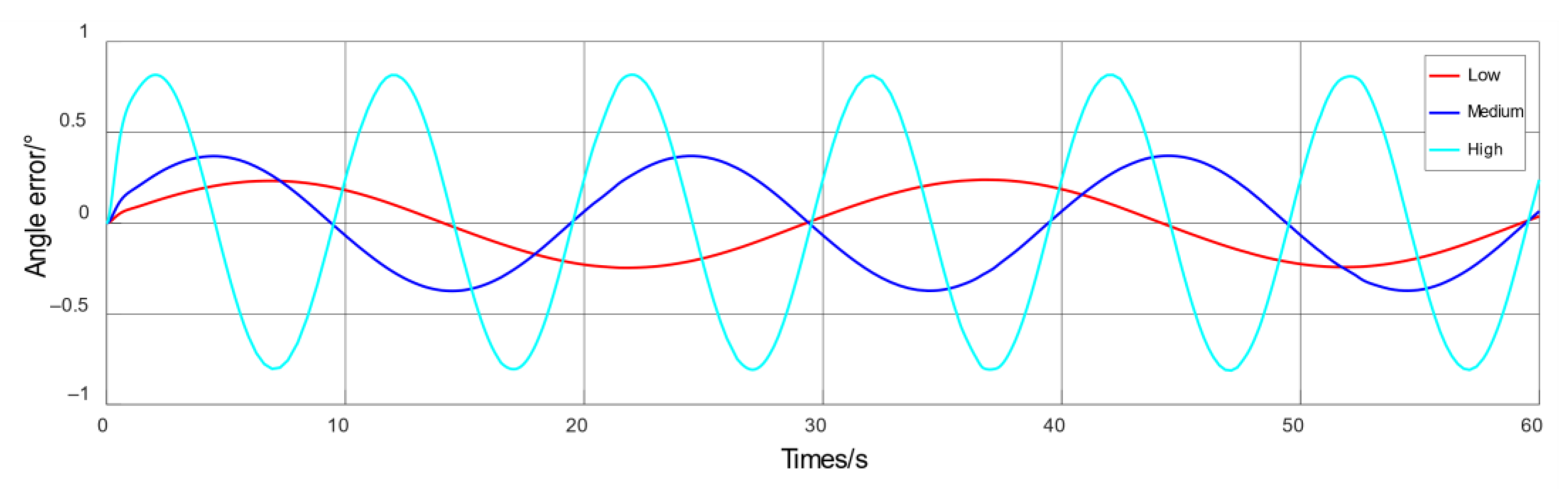
Passive training is a training mode for patients in the early stage of rehabilitation: before started, a special rehabilitation training plan is formulated according to the actual situation of patients, and the recovery training is carried out under the condition of safe and low speed. The passive training speed is gradually increased according to the recovery situation. In order to meet the training requirements of each stage of passive training, the equal amplitude, variable frequency sinusoidal signal simulation is carried out and the results are shown in Figure 7. We can estimate the final speed from the curve in Figure 7. The low speed is about 0.046 rad/s, the medium speed is about 0.070 rad/s, and the high speed is about 0.140 rad/s.
As shown in Figure 8, the simulation objects with different weights can quickly and accurately track the desired trajectory signal under the three speed-modes, without obviously exceeding the expected signal. Under the condition of the same load with different training speeds, the tracking errors of 50 kg simulation object are ±0.22°, ±0.35°, and ±0.72° respectively; the tracking errors of 80 kg simulation object are ±0.24°, ±0.37°, and ±0.81° respectively. With the increase of training speed, the tracking error increases. In the case of different loads with the same speed, the errors are ±0.22° and ±0.24° respectively in the low-speed mode; ±0.35° and ±0.37° respectively in the medium-speed mode, and ±0.72° and ±0.81° respectively in the high-speed mode. With the increase of the load weight, the tracking error increases, but the error increase is small, which proves that the robustness of passive training is ensured.
5. Passive Training Experiment of Elbow Rehabilitation Robot
5.1. Experiment on Safety Performance of Passive Training
The experimental system consists of four parts: air source system, drive system, control system, and mechanical system. We choose the embedded controller CX2040 from Beckhoff in Germany, the CHA38B6-12B-GDC24R1 single-turn absolute encoder produced by Changchun Changhui Optoelectronics Technology Co., Ltd., and the proportional pressure regulating valve ITV2050-212N from SMC in Japan.
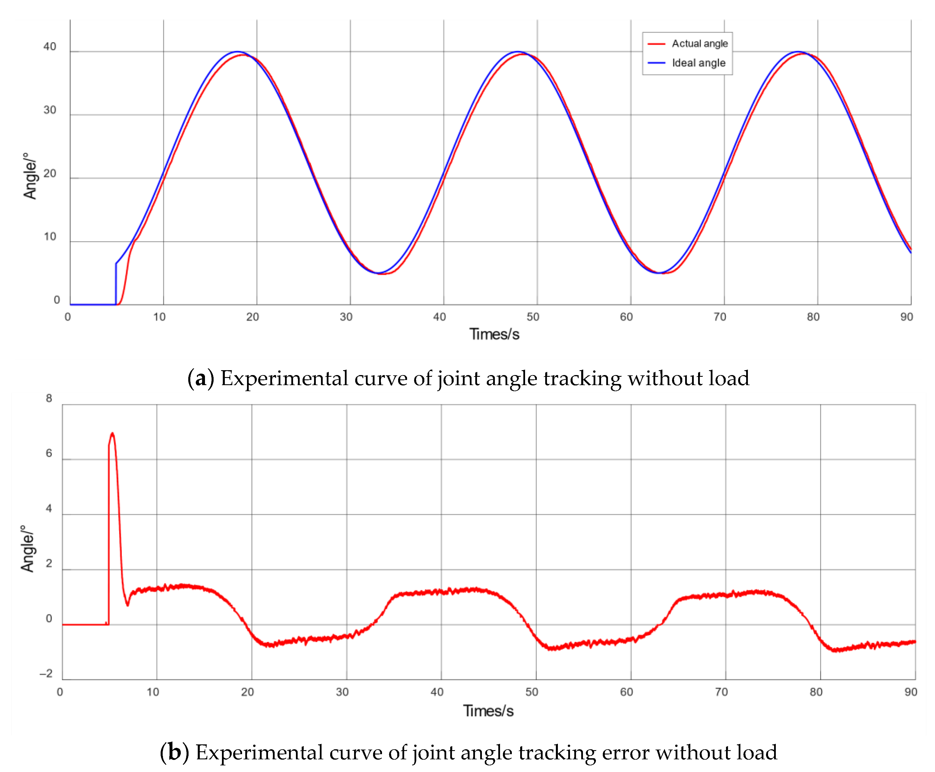
First, in the passive training safety experiment, the periodic angle signal is given, with a cycle of 30 s and the movement angle ranging from 5 to 40°. As the passive training process starts slowly, the 5 s preparation time is reserved, when the elbow joint remains at 0° position. The process of rehabilitation training is shown in Figure 9, Steps 1–3 represent the process of extending the rehabilitation arm from the initial vertical state to the maximum angle, and Steps 4–6 represent the process of contracting the rehabilitation arm to the initial vertical state. The experimental effect curve is shown in Figure 10.
According to the joint angle tracking curve shown in Figure 10, after 5 s initial preparation stage, the expected signal mutates from 0° to 5° and the actual output curve keeps up with the expected signal in 6.8 s. The tracking trajectory is smooth overall, and the final angle error is stable in −1–1.5° with a good tracking effect: the actual rehabilitation trajectory can quickly and accurately keep up with the expected deflection angle signal, without any obvious exceedance of the given angle range. The safety performance of the robot has been verified. However, due to the hysteresis characteristics of the pneumatic muscle, there is a little phase difference between the actual angle and the expected angle.
5.2. Robust Performance of Passive Training and Mechanism Rationality Experiment
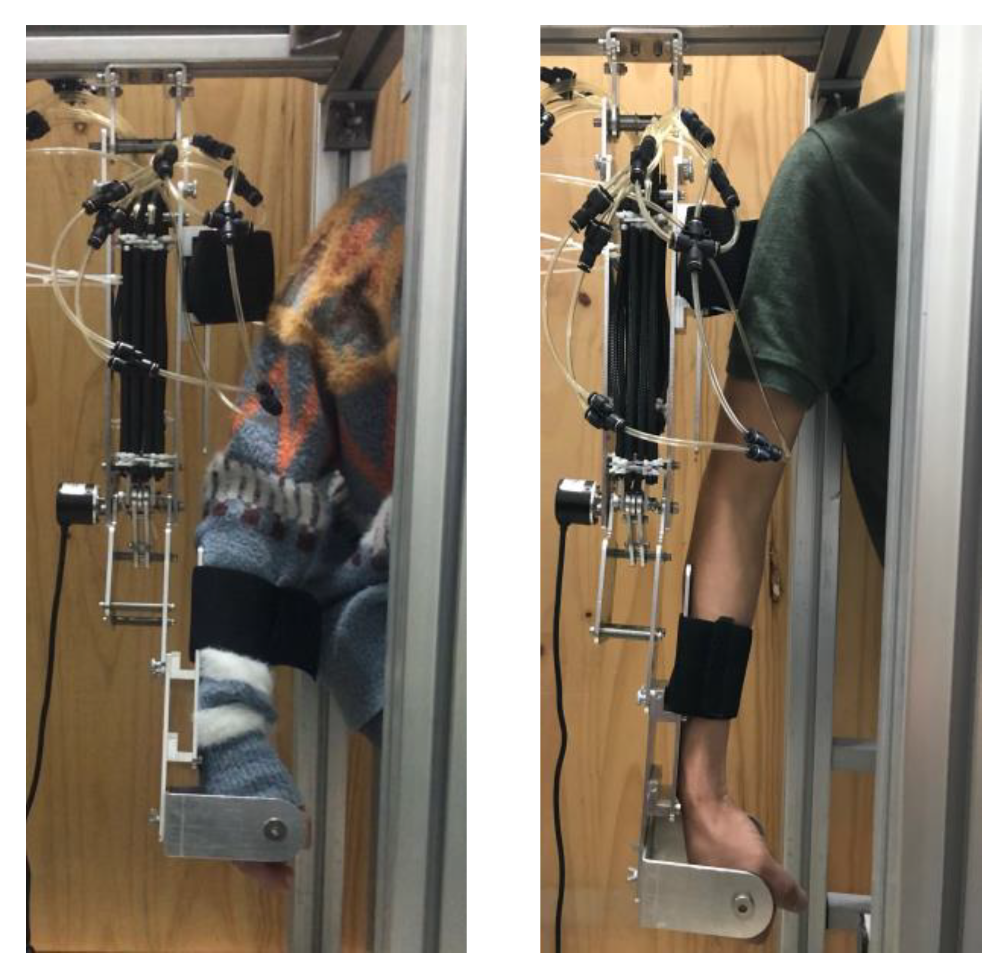
In the experiment of passive training robustness and mechanism rationality, due to the limitation of experimental conditions, the subjects of this experiment are adults with normally functional upper limbs. Before each experiment, the robot size should be adjusted according to the limb size of the subject to ensure that the elbow axis of the patient is consistent with the axis of the robot joint. Adults with different body weights and arm lengths are selected as subjects. The movement of the elbow joint rehabilitation robot is mainly in the form of flexion and extension [27]. The expected angle signal is , with a cycle of 30 s and motion angle ranging from 5 to 40°. The very first 5 s is the preparation time, and the elbow joint remains at 0° position. The subject information is shown in Table 4 and the gender of the test subjects is male; the photo of the subject wearing the rehabilitation robot is shown in Figure 11, and the experimental effect curve is shown in Figure 12.
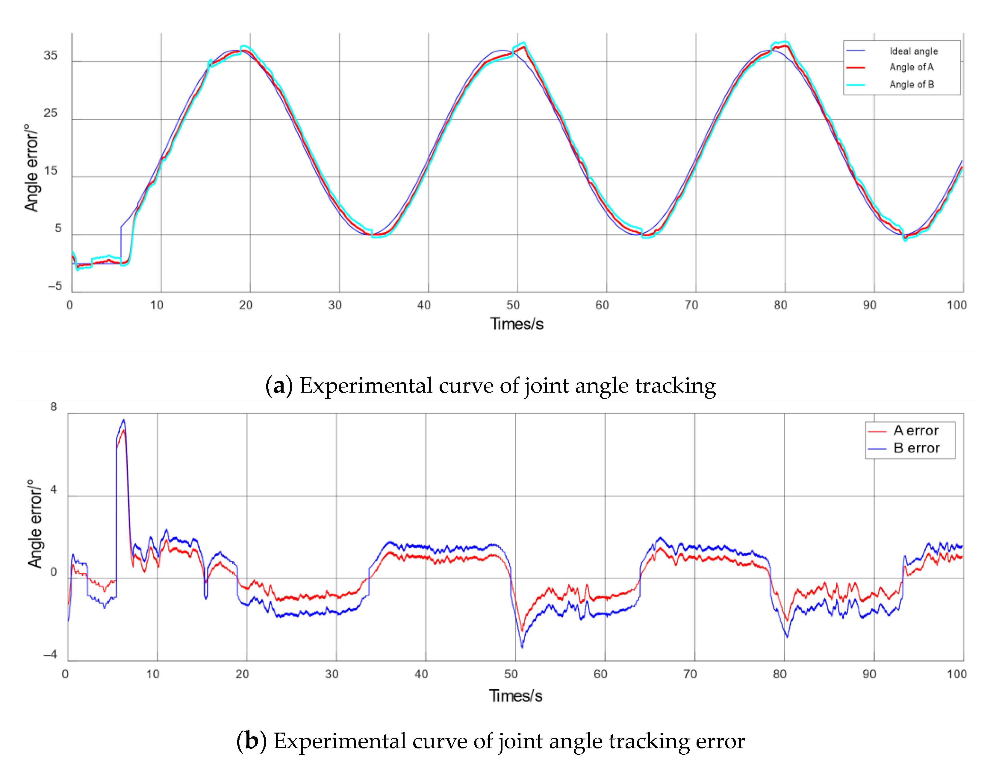
By analyzing the experimental passive training curve of the subject shown in Figure 10, after the initial 5 s preparation stage, the expected signal mutates from 0° to 5° and the actual rehabilitation trajectory tracks the expected signal at 7.2 s and 7.4 s respectively, and the final angle error ranges from −1–1.2° and −2–1.8°: the actual rehabilitation trajectory can track the expected deflection angle signal quickly and accurately. In the control experiment, due to the increase of load mass, the angle error increases, and the time required to track the desired signal increases, which is consistent with the simulation results. However, there is an obvious error increase in the amplitude. The analysis shows that the subject in the experiment is not a patient whose are cannot function at all. When the rehabilitation robot moves to the amplitude, the error increase is due to the subject’s positive force. Due to the hysteresis characteristic of the pneumatic muscle, there is a little phase difference between the actual angle and the expected angle. In the rehabilitation process, the robot does not interfere with the human body, and the user does not feel any uncomfortable. The robustness of the control algorithm and the rationality of the mechanism design are verified.
6. Discussion
Aiming at the passive training mode of the elbow rehabilitation robots actuated by pneumatic muscle, the ADRC method is adopted to solve the joint angle tracking problem. Through the simulation of no-load motion and variable-load motion of the rehabilitation robot under different ideal input signals, the results show that the ADRC has better effect and robustness.
This article focuses on the rehabilitation training of the elbow joint of the upper limb, while the upper limb of the human body is composed of shoulder, elbow and wrist joint composition, and human daily life needs multi-joint cooperation to complete. Therefore, the shoulder and wrist joints can be added into the physical sample machine in our future work, and the multi-joint cooperation is used to complete the basic daily life for better rehabilitation effect.
7. Conclusions
This paper designs the passive training experiments of the elbow rehabilitation robot and the experiments without load at the low, medium, and high-speed modes. The four-bar linkage elbow joint rehabilitation robot is driven by a small diameter McKibben pneumatic muscle bundle. The elbow contraction/extension exercise test proves the safety of the robot rehabilitation process. Passive training experiments with healthy people with different heights and weights as experimental subjects verified the rationality and comfort of the mechanism design and evaluated the robustness of the rehabilitation robot, which proved the effectiveness and feasibility of the ADRC algorithm.
Author Contributions
Conceptualization, Data curation, Methodology, Writing—review & editing, X.C.; Funding acquisition, Project administration, Resources, Supervision, B.W.; Formal analysis, Software, Writing—original draft, H.L.; Investigation, Validation, Visualization, J.C.; All authors have read and agreed to the published version of the manuscript.
Funding
This research was funded by the National Natural Science Foundation of China under Grant (61903351). This work was also supported by National Key Technologies Research and Development Program of China (2018Y FB2101004).
Institutional Review Board Statement
Ethical review and approval were waived for this study, due to the experiment carried out with the consent of the research subjects.
Informed Consent Statement
Informed consent was obtained from all subjects involved in the study.
Data Availability Statement
Data are contained within the article.
Conflicts of Interest
The authors declare no conflict of interest.
References
- Scalera, L.; Gasparetto, A.; Zanotto, D. Design and experimental validation of a 3-dof underactuated pendulum-like robot. IEEE/ASME Trans. Mechatron. 2019, 25, 217–228. [Google Scholar] [CrossRef]
- Ball, S.J.; Brown, I.E.; Scott, S.H. MEDARM: A rehabilitation robot with 5DOF at the shoulder complex. In Proceedings of the 2007 IEEE/ASME international conference on Advanced intelligent mechatronics, Zurich, Switzerland, 4–7 September 2007; pp. 1–6. [Google Scholar]
- Lee, H.; Kim, W.; Han, J.; Han, C. The technical trend of the exoskeleton robot system for human power assistance. Int. J. Precis. Eng. Manuf. 2012, 13, 1491–1497. [Google Scholar] [CrossRef]
- Song, Z.; Guo, S.; Xiao, N.; Gao, B.; Shi, L. Implementation of human-machine synchronization control for active rehabilitation using an inertia sensor. Sensors 2012, 12, 16046–16059. [Google Scholar] [CrossRef] [PubMed]
- Song, Z.; Guo, S.; Pang, M.; Zhang, S.; Xiao, N.; Gao, B.; Shi, L. Implementation of resistance training using an upper-limb exoskeleton rehabilitation device in elbow joint. J. Med Biol. Eng. (JMBE) 2013, 34, 188–196. [Google Scholar] [CrossRef]
- Niu, J.; Yang, Q.; Chen, G.; Song, R. Nonlinear disturbance observer based sliding mode control of a cable-driven rehabilitation robot. In Proceedings of the 2017 International Conference on Rehabilitation Robotics (ICORR), London, UK, 17–20 July 2017; pp. 664–669. [Google Scholar]
- Liang, G.; Ye, W.; Xie, Q. PID control for the robotic exoskeleton arm: Application to rehabilitation. In Proceedings of the 31st Chinese Control Conference, Hefei, China, 25–27 July 2012; pp. 4496–4501. [Google Scholar]
- Pietrala, D. The characteristics of a pneumatic muscle. In Proceedings of the EPJ Web of Conferences, Hobart, Australia, 20–24 February 2017; Volume 143, pp. 2093–2102. [Google Scholar]
- Reynolds, D.B.; Repperger, D.W.; Phillips, C.A. Modeling the dynamic characteristics of pneumatic muscle. Ann. Biomed. Eng. 2003, 31, 310–317. [Google Scholar] [CrossRef] [PubMed]
- Takosoglu, J.E.; Laski, P.A.; Blasiak, S.; Bracha, G.; Pietrala, D. Determining the static characteristics of pneumatic muscles. Meas. Control 2016, 49, 62–71. [Google Scholar] [CrossRef]
- Sugar, T.G.; He, J.; Koeneman, E.J.; Koeneman, J.B.; Herman, R.; Huang, H.; Schultz, R.S.; Herring, D.E.; Wanberg, J.; Balasubramanian, S.; et al. Design and control of RUPERT: A Device for Robotic Upper Extremity Repetitive Therapy. IEEE Trans. Neural Syst. Rehabil. Eng. 2007, 15, 336–346. [Google Scholar] [CrossRef] [PubMed]
- He, J.; Koeneman, E.J.; Schultz, R.S.; Herring, D.E.; Wanberg, J.; Huang, H.; Sugar, T.; Herman, R.; Koeneman, J.B. RUPERT: A Device for Robotic Upper Extremity Repetitive Therapy. In Proceedings of the 2005 IEEE Engineering in Medicine and Biology 27th Annual Conference, Shanghai, China, 1–4 September 2005; pp. 6844–6847. [Google Scholar]
- Balasubramanian, S.; Wei, R.; Perez, M.; Shepard, B.; Koeneman, E.; Koeneman, J.; He, J. RUPERT: An exoskeleton robot for assisting rehabilitation of arm functions. In Proceedings of the 2008 Virtual Rehabilitation, Vancouver, BC, Canada, 25–27 August 2008; pp. 163–167. [Google Scholar]
- Ghobj, S.; Akl, A.; El-Farr, A.; Ayyash, M.; Abu-Khalaf, J. Mechanical design for a cable driven upper limb exoskeleton prototype actuated by pneumatic rubber muscles. In Proceedings of the 2017 International Conference on Research and Education in Mechatronics (REM), Wolfenbuettel, Germany, 14–15 September 2017; pp. 1–7. [Google Scholar]
- Wu, J.; Huang, J.; Wang, Y.J.; Xing, K.X.; Xu, Q. Fuzzy PID control of a wearable rehabilitation robotic hand driven by pneumatic muscles. In Proceedings of the 2009 International Symposium on Micro-NanoMechatronics and Human Science, Nagoya, Japan, 9–11 November 2009; pp. 408–413. [Google Scholar]
- Wu, J.; Huang, J.; Wang, Y.J.; Xing, K.X. RLSESN-based PID adaptive control for a novel wearable rehabilitation robotic hand driven by PM-TS actuators. Int. J. Intell. Comput. Cybern. 2012, 5, 91–110. [Google Scholar] [CrossRef]
- Kurumaya, S.; Nabae, H.; Endo, G. Design of thin McKibben muscle and multifilament structure. Sens. Actuators A Phys. 2017, 261, 66–74. [Google Scholar] [CrossRef]
- Wakimoto, S.; Suzumori, K.; Takeda, J. Flexible artificial muscle by bundle of McKibben fiber actuators. In Proceedings of the 2011 IEEE/ASME International Conference on Advanced Intelligent Mechatronics (AIM), Budapest, Hungary, 3–7 July 2011; pp. 457–462. [Google Scholar]
- Zheng, Q.; Gao, Z. An energy saving, factory-validated disturbance decoupling control design for extrusion processes. In Proceedings of the 10th World Congress on Intelligent Control and Automation, Beijing, China, 6–8 July 2012; pp. 2891–2896. [Google Scholar]
- Sun, M.; Chen, Z.; Yuan, Z. A practical solution to some problems in flight control. In Proceedings of the 48th IEEE Conference on Decision and Control (CDC) held jointly with 2009 28th Chinese Control Conference, Shanghai, China, 15–18 December 2009; pp. 654–659. [Google Scholar]
- Xu, X.; Kou, C.H. Stabilization of an Orr-Sommerfeld equation cascaded by both the Squire equation and ODE subject to boundary control matched disturbance via active disturbance. IMA J. Math. Control Inf. 2020, 37, 120–142. [Google Scholar] [CrossRef]
- Guerrero-Castellanos, J.F.; Rifaï, H.; Arnez-Paniagua, V.; Linares-Flores, J.; Saynes-Torres, L.; Mohammed, S. Robust active disturbance rejection control via control Lyapunov functions: Application to actuated-ankle–foot-orthosis. Control Eng. Pract. 2018, 80, 49–60. [Google Scholar] [CrossRef]
- Pujana-Arrese, A.; Mendizabal, A.; Arenas, J.; Prestamero, R.; Landaluze, J. Modelling in Modelica and position control of a 1-DoF set-up powered by pneumatic muscles. Mechatronics 2010, 20, 535–552. [Google Scholar] [CrossRef]
- Han, J. Active Disturbance Rejection Control Technology. Front. Sci. 2007, 1, 24–31. [Google Scholar]
- Salahuddin, B.; Warren, H.; Spinks, G.M. A comprehensive test method for measuring actuation performance of McKibben artificial muscles. Smart Mater. Struct. 2021, 30, 045016. [Google Scholar] [CrossRef]
- Lu, R.; Jiang, Q.; Zhang, Y.; Song, M. Ergonomics; Basic Textbook for Art Design Majors in Colleges and Universities; Chongqing University Press: Chongqing, China, 2014; Volume 9, p. 199. [Google Scholar]
- Yun, D.; Khan, A.M.; Yan, R.J.; Ji, Y.; Jang, H.; Iqbal, J.; Han, C. Handling subject arm uncertainties for upper limb rehabilitation robot using robust sliding mode control. Int. J. Precis. Eng. Manuf. 2016, 17, 355–362. [Google Scholar] [CrossRef]
Figure 1.
Three view drawing of rehabilitation robot.

Figure 2.
Sketch of the structure of a four-link elbow joint.

Figure 3.
Simulation curve of ADRC tracking step input signal.

Figure 4.
Simulation curve of PID control tracking step input signal.

Figure 5.
Simulation curve of ADRC control tracking sinusoidal input signal.

Figure 6.
Proportional valve control voltage.

Figure 7.
Simulation tracking curve with low, medium, high speed movement.


Figure 8.
Simulation curve of equal amplitude variable frequency sinusoidal signal.

Figure 9.
Passive training process under no load.

Figure 10.
Curve graph of passive training experiment under no-load.

Figure 11.
Effect picture of experiment subjects wearing rehabilitation robot.

Figure 12.
Experimental passive training curve of the subjects.


Table 1.
Parameters of active disturbance rejection controller simulation under step signal.
| Parameters | ||||||
| Value | 10,000 | 0.1 | 0.5 | 0.25 | 0.05 | 0.05 |
| Parameters | - | |||||
| Value | 1000 | 1400 | 500 | 20,000 | 2000 | - |
Table 2.
Parameters of PID controller simulation under step signal.
| Parameters | P | I | D |
|---|---|---|---|
| Parameter 1 | 50 | 300 | 3 |
| Parameter 2 | 20 | 0 | 5 |
Table 3.
Simulation of ADRC parameters under sinusoidal signal.
| Parameters | ||||||
| Value | 2000 | 0.01 | 0.5 | 0.25 | 0.05 | 0.05 |
| Parameters | - | |||||
| Value | 50 | 3000 | 13,000 | 50 | 300 | - |
Table 4.
Subject information.
| Subjects | A | B |
|---|---|---|
| Height (m) | 1.60 | 1.82 |
| Weight (kg) | 48 | 82 |
| Arm length (m) | 0.4 | 0.53 |
Publisher’s Note: MDPI stays neutral with regard to jurisdictional claims in published maps and institutional affiliations. |
© 2021 by the authors. Licensee MDPI, Basel, Switzerland. This article is an open access article distributed under the terms and conditions of the Creative Commons Attribution (CC BY) license (https://creativecommons.org/licenses/by/4.0/).
Share and Cite
MDPI and ACS Style
Cui, X.; Wang, B.; Lu, H.; Chen, J. Design and Passive Training Control of Elbow Rehabilitation Robot. Electronics 2021, 10, 1147. https://doi.org/10.3390/electronics10101147
AMA Style
Cui X, Wang B, Lu H, Chen J. Design and Passive Training Control of Elbow Rehabilitation Robot. Electronics. 2021; 10(10):1147. https://doi.org/10.3390/electronics10101147
Chicago/Turabian StyleCui, Xiaohong, Binrui Wang, Han Lu, and Jiayu Chen. 2021. "Design and Passive Training Control of Elbow Rehabilitation Robot" Electronics 10, no. 10: 1147. https://doi.org/10.3390/electronics10101147
Note that from the first issue of 2016, this journal uses article numbers instead of page numbers. See further details here.