
Review of Cyber-Physical Attacks in Smart Grids: A System-Theoretic Perspective


1
Department of Computer, Control, and Management Engineering “Antonio Ruberti” (DIAG), University of Rome “La Sapienza”, Via Ariosto 25, 00185 Rome, Italy
2
Department of Control and System Analysis, Universite Libre de Bruxelles, 1050 Brussels, Belgium
*
Author to whom correspondence should be addressed.
Electronics 2021, 10(10), 1153; https://doi.org/10.3390/electronics10101153
Submission received: 4 February 2021
/
Revised: 4 May 2021
/
Accepted: 6 May 2021
/
Published: 12 May 2021
(This article belongs to the Special Issue Cyber-Physical Security in Smart Grids: System Analysis and Control Design)
Abstract
:This paper presents a review of technical works in the field of cyber-physical attacks on the smart grid. The paper starts by discussing two reference mathematical frameworks proposed in the literature to model a smart grid under attack. Then, a review of cyber-physical attacks on the smart grid is presented, starting from works on false data injection attacks against state estimation. The aim is to present a systematic and quantitative discussion of the basic working principles of the attacks, also in terms of the inner smart grid vulnerabilities and dynamical properties exploited by the attack. The main contribution of the paper is the attempt to provide a unifying view, highlighting the fundamental aspects and the common working principles shared by the attack models, even when targeting different subsystems of the smart grid.
1. Introduction
A cyber-physical system (CPS) is a system that works based on a strong interplay between computing, information and communication technology functionalities, and physical processes and dynamics [1]. CPSs are pervasive in today’s society. Examples go from miniaturized systems up to systems spanning entire nations. The smart grid is arguably the most complex and critical CPS. Therefore, the study of security issues in smart grids attracts a huge amount of research. Among the most recent review papers on smart grid attacks there are: [2], providing a comprehensive survey on the security requirements, types of attacks, countermeasures, and research challenges (mainly from the information technology point of view) [3], an extensive survey paper including an excellent qualitative discussion and classification of the attacks and related defense strategies [4], focusing on CPS testbeds [5], which presents a list of possible vulnerabilities and attacks [6], presenting a comprehensive discussion of attack-resilient architectures and methods for wide area control and monitoring in smart grids [7], discussing the main smart grid standards and associated vulnerabilities, and existing CPS testbeds [8], providing a classification of threats in the smart grid [9], proposing risk assessment methodologies, and methods to evaluate the likelihood of attacks and the resiliency of a smart grid subject to attacks [10], with a survey of methods for secure design, detection, identification, restoration, and resilient control of smart grids [11], discussing vulnerabilities and threats of phasor measurement units (PMUs) and the global positioning system (GPS), which are key smart grid communication technologies [12], on generic CPSs, but presenting also a classification of attack types in smart grids [13], presenting a high-level survey of attacks and detection methods in industrial CPSs, and relevant also for smart grids [14], providing an excellent review of the main control systems and operations in the different smart grid domains, as well as a comprehensive discussion of the existing defence strategies [15], providing a recent overview of cyber-physical attacks against the smart grid, and available defense strategies [16], providing a comprehensive overview of threat modelling in energy CPSs, including the possible attack entry points, the CPS vulnerabilities, a list of scenario-specific physical and cyber metrics to assess the performance of the CPS under attack; the paper also presents an elaborated adversarial model (to capture the attacker’s capabilities, resources, etc.), and an attack model (to capture the characteristics of the attack); finally, three practical scenarios are discussed.
Compared to the above ones, this review provides a discussion which is more comprehensive, by covering multiple areas of the smart grid, and multiple types of attacks. The objective is also to provide a more in depth and critical discussion, by presenting a quantitative formulation of the different attack models, also highlighting how ideas have evolved from the formulation of the first, simple attack models, to the most recent and complex ones.
Several research and innovation projects have significantly contributed to advance the knowledge in the sector. This is the case for example of the EU-funded Viking project [17], which contributed significantly to the investigation in the areas of state estimation (SE) and automatic generation control (AGC). Other relevant recent innovation projects include: SPEAR (“Secure and PrivatE smArt gRid”) [18], ENERGY SHIELD (“Integrated Cybersecurity Solution for the Vulnerability Assessment, Monitoring and Protection of Critical Energy Infrastructures”) [19], PHOENIX (“Electrical Power System’s Shield against complex incidents and extensive cyber and privacy attacks”) [20], DEFENDER (“Defending the European Energy Infrastructures”) [21], SDNmicroSENSE (“SDN—microgrid reSilient Electrical eNergy SystEm”) [22], SUCCESS (“Securing Critical Energy Infrastructures”) [23].
1.1. Purpose, Rationale and Structure of the Review
This paper presents a review of the possible cyber-physical attacks against a smart grid. The purpose is to present a quantitative discussion, focused on explaining the inner properties of the smart grid that the different cyber-physical attacks leverage to cause disruption. A system-theoretic approach is adopted for the modelling and analysis of: (i) the smart grid, seen as a CPS; (ii) the attacks, with the related assumptions and dynamics; (iii) the effects of the attacks on the smart grid. The review proposes a wide and comprehensive discussion, covering different areas of the smart grid, from generation, to transmission and consumption.
The main contribution of this survey with respect to the existing literature is that it does not only provide an overview of the main attacks on the grid studied in the literature, but it also tries to analyse them under a unifying system-theoretic perspective, which better highlights conceptual similarities and common working principles, showing, for example, how ideas developed in the analysis of specific attacks can be exploited in the design of attacks targeting different areas of the grid, or also how attack schemes can be combined to engineer more and more complex and refined attacks.
The paper is structured into two main parts. The first one discusses two modelling frameworks for CPSs, recently proposed in literature, which are useful for the purpose of providing a conceptual basis to model and classify the attacks. Key nomenclature is discussed as well. The second part reports the review of the cyber-physical attacks, focusing on the analysis of the physical consequences (e.g., loss of service, damage to equipment, etc.) that can be caused by either pure cyber attacks or by attacks combining cyber and physical disruption. The review does not discuss pure cyber vulnerabilities, and the related techniques used to launch cyber attacks.
There are several ways to classify and present attacks (e.g., by working principle, by targeted system, etc.). In this review, we first analyse false data injection attacks (FDIAs) against SE, one of the first attacks to be investigated in the literature. This attack impacts one of the most critical smart grid control functions, and can have catastrophic cascade effects at all levels of the smart grid. The review of the attacks then follows the logic flow of the control operations performed in the power systems, as explained in Section 3. Finally, attacks directly targeting grid devices and customers are discussed.
The rest of the paper is organized as follows: Section 2 focuses on the modelling of a CPS subject to attacks, also discussing a simple model of the attack space. Section 3, reviews the main cyber-physical attacks on smart grids. Section 4 presents a discussion of the findings and gives an overview on current research trends. Section 5 concludes the paper.
1.2. Notation
The symbol:= means equal by definition; ∅ or denote the empty set; denotes the set of real numbers; denotes the space of vectors of real numbers of dimension n; is the cardinality of set K; denotes the i-th entry of vector x; denotes the dimension of the generic vector v; ; ; given , ; ; given a matrix , denotes the transposed matrix; the kernel (or null space) of A: ; the image (also called, span, or range) of A: , a matrix norm; I the identity matrix.
2. Modelling of CPSs Subject to Attacks
This section reviews two of the most relevant frameworks presented in literature for modelling CPSs subject to attacks. The third subsection outlines how the frameworks can be used to model some of the most important cyberattacks (bias injection, denial of service (DoS), etc.), which are, in most of the cases, the basic building block used in the smart grid cyber-physical attacks reviewed in Section 3.
2.1. Modelling of the CPS Subject to Attacks by Using Deterministic Linear Descriptor Systems
A first set of works, by Pasqualetti et al., which consider the cases where a CPS can be modeled as a deterministic linear time-invariant descriptor system [24,25,26]:
where is the state of the system and the output at time t. Matrix E is in general singular, so that (1a) includes in general both algebraic and differential equations. The attack is modelled through the signals and , which are decided by the attacker, with . With no loss of generality, it is assumed that can affect independently each state and output variable (i.e., and ). The attack set, , is the set of the components of u which are different from zero for some t. The attack mode is the subvector of u indexed by K. The attack signature is the couple of submatrices of B and D with columns indexed by K (so that and ). Attacks such as are called state attacks, since they directly target only (1a) (but they can impact the whole system), whereas attacks such as are called output attacks. Modelling the attack as an additive signal in (1a) and (1b) allows capturing a number of different cases, such as [25] physical attacks, which can be modelled as state attacks, attacks to actuators, also modelled as state attacks, attacks to sensors, modelled as output attacks, and so forth.
Attack Detection and Identification
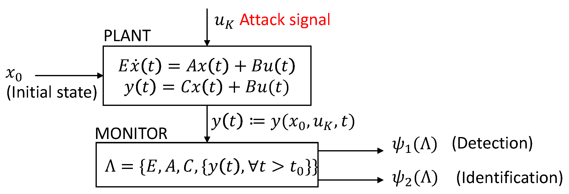
After the CPS and the adversary are modelled, in [25] the notion of monitor is characterized, in a deterministic setting. The monitor hosts algorithms for attack detection (i.e., to understand if an attack is ongoing or not), and identification (i.e., to find the attack set). It is assumed that the monitor has full knowledge of the system model (i.e, E, A, C) and of the measurements , (monitoring starts at ). The monitor is defined as a deterministic system with input (, or, concisely, , denotes the output of the system at , when and the input is applied between times and t. and with output (Figure 1).
It is , depending on whether or not the detector reports an attack, while is the list of components of the attack vector u that the monitor marks as being active. The output of the monitor might or might be not in line with the reality (e.g., false negative and false positive may happen).
Consistency properties are introduced to describe the correct behavior of the monitor. The way the consistency properties are defined depends in general on the adopted CPS modelling framework (for example, stochastic modelling frameworks require in general different properties than deterministic ones). In [25], the consistency properties proposed for the deterministic framework are:
- only if there is actually an attack. Equivalently, , that is, false positives are excluded;
- if and only if (an internal coherency property of the detector);
- only if there is no other attack set , , such that there exists an initial state and an attack signal such that , (i.e., no other attack set with equal or smaller cardinality can “explain” the attack). If this cannot be assured, then it is .
An attack is detected by a monitor if . It is identified if . An attack is undetectable (unidentifiable) if and only if there is no consistent monitor that can detect (identify) it (notice that, it is necessary to consider consistent monitors, since, for example, any monitor such that would detect all attacks, but with unacceptable rate of false positives). Similarly, an attack set K is undetectable (unidentifiable) if there exists at least an undetectable (unidentifiable) attack [25]. An undetectable attack is also unidentifiable (because of consistency property 2). Moreover, a non-zero attack is undetectable if and only if , , for some initial states . That is, the output of the system under attack is the same as the output under no attack, but from a different initial state (i.e., the attack produces outputs that are compatible with some normal operative condition). In the above, the initial state is supposed to be unknown to the operator. In case instead it is known, the condition is . In addition, since the considered CPS model is linear, the condition for some is equivalent to the condition , , for some . In system theory terminology, the above means that undetectable attacks only excite the zero dynamics of the system (i.e., state trajectories which are associated with zero output).
An attack is unidentifiable if and only if for some , and for some attack signal , with and (see consistency condition 3 above). The papers [24,25] give a number of conditions to practically check if a given system admits undetectable/unidentifiable attacks, and give also centralized and distributed formulations of detectors. For what follows, it is useful to recall here the formulation of the centralized observer-based detector proposed in [25]:
with w the state of the detector and r the so called residual. It is proven in [25] that, under proper assumptions, if the attack set is detectable, and the state of the detector is initialized at the state of the plant, then if and only if (i.e., there is no attack), and is exponentially stable (i.e., the state of the detector approximates the state of the plant). If the initial state of the system is not known, the observer can be initialized with an arbitrary initial state, and still the residue will converge to zero if there is no attack. Detector (2) is just an example of the many ones proposed in literature. The study of the mathematical properties of detectors plays a fundamental role, as one of the general goals of an attacker is to construct attacks which can bypass the detection strategy adopted by the operator. To conclude, Pasqualetti et al. in [25] consider mainly omniscient adversaries (who have full knowledge of the system model), whose objective is to disrupt the system while remaining undetected/unidentified.
2.2. Modelling of Networked CPSs under Attack
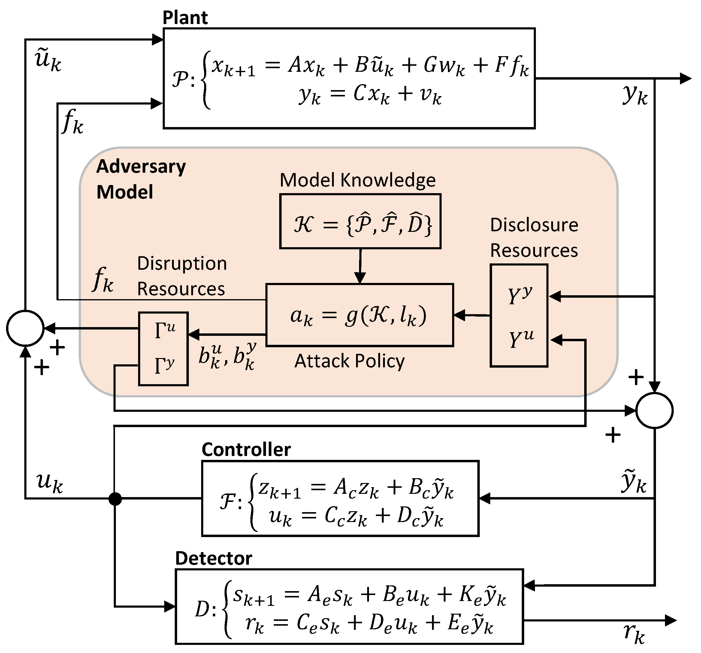
A second very interesting modelling framework is detailed by Teixeira et al. in [27,28], and references therein from the same authors. A networked CPS is modelled as comprising a plant, a feedback controller and a detector, all modelled as linear time invariant systems in discrete time (k denotes the time variable). The attacker-CPS interaction is illustrated in Figure 2.
In this modelling framework, the plant, the controller, and the detector are modelled separately, with their respective connections and communication links (whereas in the previous framework they are all modelled by a single descriptor system—see Figure 1). The plant is impacted by a noise term on the state (), and by a noise term on the output (). is the control, as computed by the controller, is the plant output, as measured by the sensors. Attacks in this model can happen in the form of a physical disruption of the system and/or corruption of control and/or measurement packets. models physical attacks, impacting the system according to F. and denote, respectively, the control input and the plant output measurement, as possibly corrupted by the adversary. The system is said to have a nominal behaviour when , and (i.e., when there is no attack) [28].
2.2.1. Attack Space and Adversary Model
Teixeira et al. consider in [28] a three-dimensional attack space model, by characterizing the attacks in terms of:
- The model knowledge, i.e., the adversary’s a priori knowledge about the CPS;
- The disclosure resources, i.e., the information that the attacker is able to retrieve about the system during the attack (violation of confidentiality);
- The disruption resources, i.e., integrity/availability violations through which the attacker compromises the system (e.g., through manipulation of the system’s control inputs, measurements, etc.).
In [28], the adversary model is given as the combination of the adversary resources (model knowledge, disclosure resources and disruption resources), and the attack policy g (for the attacker to decide how to attack the system based on the information available).
The model knowledge represents the a priori knowledge of the adversary about the CPS. Different attacks may have different requirements in terms of model knowledge.
The disclosure resources are the entries of and to which the adversary has reading access. They are denoted with sets and . Then, the information, , gathered by the adversary from a given initial time up to a generic time , can be modelled as:
where and are binary matrices selecting the entries of and corresponding to the disclosure resources, respectively.
Disruption resources can be of two types: (i) physical attacks, and (ii) data deception. models physical attacks, which impact on the plant dynamics. Matrix F represents the physical attack resources. It captures how impacts on the system. With the data deception resources, the attacker corrupts measurements and/or the computed control , by injecting the attack signals and . The sets and denote the disruption resources associated with data deception [28], that is, the system’s inputs and outputs that the adversary can corrupt, by injecting the corrupting signals and , respectively.
where the binary incidence matrices and map each entry of to the corresponding disruption resource. To summarize, the overall attack signal has the following structure, including both physical and data deception disruption resources:
Finally, the attack policy g determines the physical attack and the data deception attack , based on the model knowledge and the accumulated data .
2.2.2. Stealthy and Successful Attacks
Teixeira et al. consider in [28] a residue-based detector, which issues an alarm if and only if the residue measured over a given detection time , that is, , lies outside of a pre-specified region . Two consistency properties are given for the detector. They differ from the ones in [26], also because the system is impacted by noise. An attack is stealthy if and only if (i.e., the residue remains in the region for which no alarm is raised). An attack is successful if the state of the CPS is driven outside a given safety region, [28].
2.3. Modelling of Basic Attacks
The above frameworks allow to model most of common attacks, including for example:
- Eavesdropping attacks, in which the adversary acquires some data transmitted in the CPS (3). The attacker posses only disclosure resources. These attacks are functional to collect the model knowledge needed to later carry out a disruptive attack;
- FDIAs (or data deception attacks), aimed at compromising the integrity of control and/or measurement packets, or some other information in the system. They can be modelled as in (4a) and (4b). In bias injection attacks, the attacker injects at steady state a constant bias in the communication channels, with the aim to cause disruption, while remaining undetected. Simple bias injection attacks only require disruption resources, and model knowledge, to optimize the bias value to be injected. More complex FDIAs include for example covert attacks [29], in which the attacker can alter the output of the system without being detected. Referring to Figure 2, this means in practice that the attacker can arbitrarily control system output , while keeping unaffected. Finally, in zero-dynamics attacks, the attack is designed so as to be decoupled from (i.e., have no impact on) the residual (see Section 3.12);
- DoS attacks [30] are meant to interrupt some or all of the communication channels in the system, making impossible for the sensor and/or the control data to reach the destination. As shown in [28], they can be modelled as FDIAs by properly selecting and in (4). No model knowledge and disclosure resources are needed to implement simple DoS attacks. The disruption resources are the data channel that the adversary is able to impact;
- In replay attacks [31], the attacker hijacks certain sensors, records readings from them for a certain amount of time, and then repeats (i.e., replays) the readings on the monitoring channels, while possibly injecting an exogenous signal into the system. Recording can be modelled as in (3), replay as in (4). Replay can have the purpose of covering simultaneous cyber-physical attacks, delay/impede detection, and so forth. Disclosure resources are the channels from which the attacker can record. The disruption resources are in general a subset of the disclosure resources, plus the physical attack resources modelled by F. No model knowledge is needed for the basic versions;
- In time delay attacks, the attacker injects delays in the sensing and actuating channels, with the aim of disrupting operations. In particular, delays can have a detrimental impact on the stability of the system. In time synchronization attacks, the attacker breaks synchronization of data and signals, which can be crucial for the correct functioning of the CPS (Section 3.14);
- In Structural Attacks/Tampering, the attacker physically alters the system, with the aim to cause disruption. The effect of the attack can be modelled as a change in the dynamics of the system, as represented in Figure 2, through the action of the attack signal .
3. Review of Cyber-Physical Attacks to the Smart Grid
3.1. Reference Smart Grid Architecture for the Review
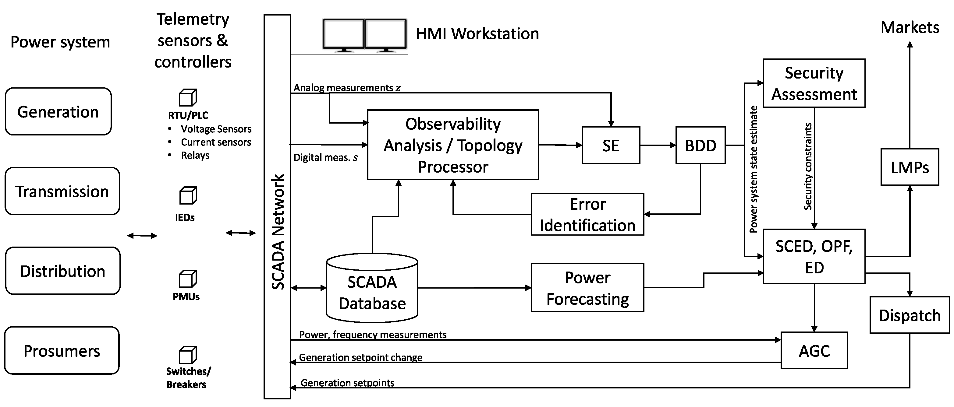
Figure 3 reports a simplified view of the smart grid operation and control systems relevant for the cyber-physical attacks discussed in this paper. Details on these systems can be found, for example, in [32,33].
Many smart grid control systems operate based on grid SE, which is provided in near real time (e.g., every 5 min) by the SE module of the supervisory control and data acquisition (SCADA) system in the control center. The SE module filters and fuses the data collected in real time from the grid through the SCADA, including primarily the continuous signal measurements (line power flows and bus injections, voltage and current sensors, voltage and phase angle measurements from PMUs, etc.) and logic state measurements, that is, information on the open/close state of switches and breakers at lines, substations, generators, loads, and so forth. Before SE, data are checked/filtered for errors, and an observability analysis is performed, to ensure that there are enough data to correctly perform SE. A candidate estimated network topology is also computed by the topology processor, based on the logic measurements. SE is then performed based on the measurements and the candidate topology. The estimated state of the grid is checked with bad data detection (BDD) techniques, to spot the presence of faulty measurements, which could impact SE. Error identification and correction procedures are triggered if that is the case. Attacks against SE are discussed in Section 3.2, Section 3.3 and Section 3.4. In these attacks, the attacker aims at altering the estimated state of the smart grid, by corrupting the continuous signal and/or the logic state measurements used in SE, in a way that is not detectable by the BDD.
After passing BDD, the estimated state feeds a number of other critical operations (Figure 3). Contingency analysis is carried out on a continuous basis, to evaluate the current state of security of the grid, including with simulations of the effect that a list of possible relevant contingencies (such as tripping of lines, loss of generators, etc.) would have on the grid. In case issues are detected, a security-constrained economic dispatch (SCED) grid optimisation is performed, which consists in an optimal power flow (OPF) problem integrating also security constraints deriving from the contingency analysis. SCED determines new grid setpoints (i.e., power injections and power flows in the grid) which ensure safe grid operation, also in case the analysed contingencies materialize. Attacks against contingency analysis, SCED and related operations are discussed in Section 3.5.
Similar to SCED, economic dispatch and other OPF-based procedures are programs of the energy management system (EMS) which are run to determine the best grid setpoint to ensure safe and economical operation of the grid. The outputs of these procedures typically include power generation setpoints for the generators and locational marginal price (LMPs) to determine the price of the energy for producers and consumers. Attacks against electricity markets are discussed in Section 3.7.
In parallel, the AGC system ensures that the frequency deviations from the nominal values (50 or 60 Hz) are minimized, and that the power exchanges among the various areas of the grid remain close to the optimal setpoints decided in the economic dispatch optimization. Similarly, automatic voltage control (AVC) ensures that the voltage levels remain within the admissible bounds. Attacks against AGC and AVC are discussed, respectively, in Section 3.8 and Section 3.13.
3.2. False Data Injection Attacks against State Estimation
The literature on FDIAs against SE is mostly focused on the electricity transmission sector, where, as is will be explained below, SE is typically based on a static model of the grid, derived from the power flow equations. Referring to the previous Section 2, this means that only an equation of the kind (1b) is considered in the following (i.e., the measurement Equation (8)), while no dynamics equation of the kind (1a) is considered. Recently however, some works have appeared focusing on dynamic SE, for example, via Kalman filters. In this case, a dynamical model of the grid is considered. These works are discussed briefly at the end of the next section.
3.2.1. Grid State Estimation
Grid SE is the problem of estimating the state of the electrical network based on measurements from sensors spread across the grid and retrieved through the SCADA system. In power flow applications, the state of the grid is typically described by the buses’ voltage magnitude and angle, since they completely determine the active and reactive power flows [32]:
and the active and reactive power injection at buses:
where and are the active and reactive power flows from bus i to bus j, respectively, and are the active and reactive power injections at bus i, the voltage magnitude at bus i, and are network parameters (respectively, the susceptance and conductance of line ), is the voltage angle at bus i, , is the set of buses connected to bus i through a line.
FDIA against SE (concisely, SE-FDIA) has been one of the first smart grid cyber-physical attacks studied (in [34,35]). This attack disrupts SE by altering a set of measurements in a smart way, so that the attack goes undetected. Consequences can be far reaching, possibly including physical disruption and economical losses. A key concept in SE is that of measurement model, that is, a mathematical relation linking the state variables (to be estimated) and the measured variables:
with the vector of state variables, the vector of measurements, e the vector of measurement errors (typically assumed to follow a Gaussian distribution with zero mean and diagonal covariance matrix R), and h a nonlinear function linking the state variables to the measurement variables. More measurements are available than variables to estimate (i.e., ).
SE finds an estimate which best fits the measurements z according to (8). Several SE techniques exist [33]. In the following, the common weighted least-squares estimation criterion is considered:
with . How to solve (9) in practice depends on the structure of h. In alternating current (AC) SE, the nonlinear power flow and injection Equations (6) and (7) constitute the measurement equations. Measurements typically include the active and reactive power flows at the lines and injections at the buses. The state is given by the buses voltage angles and magnitudes. In addition to the above, nowadays it is more and more the case that also PMUs are deployed at some network buses, which allow to directly measure the buses’ voltage magnitude and angle, so that the measurement vector also includes in this case voltage measurements (in addition to the power measurements).
In AC SE, the state estimate is found by solving the first-order necessary optimality condition deriving from (9), that is, , that is, , which is a nonlinear equation that can be solved, for example, via iterative techniques [33].
The early works on FDIA against SE (starting from [34,35]) considered a simplified setting, with a so called direct current (DC) measurement model: a reasonable assumption in transmission network applications is to consider bus voltages all constant at 1 per unit, and the difference in voltage angles small, so that a linear measurement model can be derived from the linearization of (6) and (7). Based on these assumptions, it is seen from (6b) that the reactive power flow is zero, and a linear measurement model of the kind can be considered (where matrix H derives from the Jacobian of (6) and (7), and depends in practice on the specific network topology, the placement of meters, the network parameters, and so forth—see, for example, [36,37] on how to compute H from (6) and (7). In DC SE, the state is thus typically given by the buses voltage angles (magnitudes are assumed constant), and the measurements by the active line power flows and buses injections.
The necessary optimality condition for (9) under a DC model leads to [38] , with the well-known weighted Moore-Penrose pseudoinverse. The “estimated measurement” is: , .
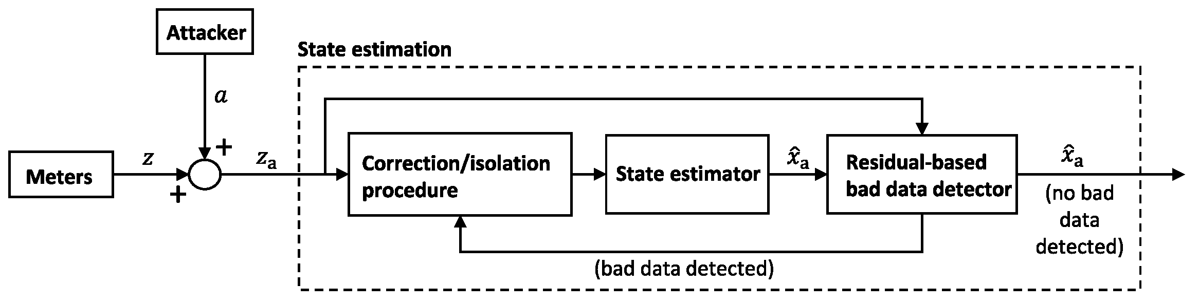
Even in a nominal scenario with no attacks, the measurement vector z is affected by the presence of bad data, for example, due to sensor failures. This will make deviate from the real state x. Therefore, BDD is performed. Several techniques exist. A common choice is the residual-based detector, which is based on the computation of the measurement residual, that is, the difference between the measurement z and the estimated measurement: . For instance, if the largest normalized residual test is used, an alarm is raised if , with the alarm threshold (its selection is a key issue: a low value increases false positives, a high value increases false negatives). Several alternative detection methods are available, like the cumulative sum, the Chi-Squared test, and so forth. In [39], interestingly, the residual is computed by fusing also the information coming from the cyber intrusion detection systems [40]. Figure 4 shows a typical layout of the SE module in the smart grid, comprising also the detector.
3.2.2. FDIA against DC State Estimation
FDIA corrupts z by injecting an attack vector a: ( is the corrupted measurement). The resulting biased residual computed by the detector is: . BDD effectively spots unstructured attacks. However, if , then , which means that passes BDD, if z does so. It was noticed in [34] that an a such that always exists. It is sufficient to take , with arbitrary c (this is easily seen, based on the previous definitions). In that case, it is , meaning that the false state is seen by the operator as a valid network state, that is, it is compatible with the attacked measurements through the measurement equation. In fact, the corrupted state estimate is: (i.e., c is exactly the bias the attacker injects in the SE).
The attack design must take into account that only a subset of the meters can be attacked in practice. Let thus denote the attack set. Then a must be selected such that:
If , then (10) is always feasible [35], and simple algorithms exist to find an attack based on performing linear operations and swapping on the columns of H [35]. In several works, (10b) is written in the equivalent matrix form , where denotes the submatrix of H with rows indexed by the complementary set of . Condition (10a) (i.e., ) instead is equivalent to [35] , with - a condition which does not include c. Several categories of SE-FDIAs have been studied. In random FDIAs [35], the attacker injects some error in the estimate. Conditions (10a) and (10b) are the necessary and sufficient ones for random attacks. In targeted FDIAs [35], the attacker aims to inject specific state estimate errors ’s into specific state variables , with the set of targeted state variables. In [35], two types of targeted FDIAs are introduced: constrained targeted FDIAs, for which it is for every (i.e., the attacker does not want to alter the estimate of the untargeted variables); unconstrained targeted FDIAs: the untargeted variables could also be impacted as a side effect.
Another distinction is between strong FDIAs and generalized FDIAs [35]. In strong FDIAs (the ones discussed so far) it is , which implies . Generalized FDIAs instead do not require . Denote as usual with the corrupted estimate, with c the error introduced in the estimate. Following computations similar to the above ones, the biased residual is . Given the triangular inequality, it is . Hence, even when , the attack remains stealthy (considering a simple threshold-based detector) as long as , that is, as long as . A generalized FDIA is therefore any attack for which .
In [42], it is highlighted that strong FDIAs are unobservable (i.e., undetectable) in the sense that there exists a feasible network state (i.e., ) which is consistent with the corrupted measurements (i.e., ) (i.e., , the undetectability condition presented in Section 2). In [42], observable islands are defined, which are subsets of network buses that share the same perceived state perturbation under attack. Then, irreducible attacks are defined in [42], as the unobservable attacks such that it is not possible to carry out unobservable attacks with only a strict subset of the attacked meters. It is also the case that 3-, 4-, and 5-sparse irreducible attacks are characterized, in case all lines are metered (being a k-sparse attack an attack carried out by corrupting k meters). Finally, countermeasures are proposed in [42], noticing that placing known-secure PMUs in separate observable islands makes the attack observable (PMUs directly observe voltage magnitudes and angles).
Early works typically consider static SE-FDIA, that is, attacks at a given time instant. Some recent works, for example, [43], which focus on PMUs (which have a measurement frequency of tens of Hz), consider FDIA in a setting in which measurements over a block of time are collected and then processed in batch. This results in a measurement equation , where Z is the matrix of measurements (where is the measurement collected by instrument j at time i), X the state vector, H the network matrix and E the measurement errors. Unobservable attacks as usual take the form of and therefore . Matrix is column-sparse, meaning that only the columns corresponding to the compromised measurement units are non-zero. The measurement matrix Z instead is low-rank [43]. Hence, in literature, convex-optimization-based decomposition methods have been developed, able to identify the attacked PMUs by separating the measurement matrix into a low rank matrix (the matrix of uncorrupted PMU measurements) and a column-sparse matrix (the attack matrix). Zhang et al. show in [43] how sophisticated attacks can be fabricated that bypass such low-rank decomposition identification techniques.
3.2.3. Security Indices and Attacker-Defender Problem Design
The analysis of an attack allows the defender to evaluate the vulnerability of the infrastructure, and to design countermeasures. In this sense, several security indices have been introduced to characterize the vulnerability of a grid to SE-FDIAs. In [37,38] and earlier papers, the security index is defined, that is, the minimum number of meters the attacker must corrupt to launch an undetectable attack:
Kosut et al. develop in [37] detectors for the weak attack regime, when the attacker controls less than meters, and investigate the trade off between the attack damage and the detection probability, as well as the possible impact of the attack on the LMPs in electricity markets (see Section 3.7).
Other indices have been proposed [38], for example, the minimum sparsity , that is, the minimum number of meters that an attacker needs to compromise to be able to inject 1 unit of attack data at meter i:
or the minimum magnitude , that is, the minimum attack signal magnitude necessary to be able to inject 1 unit of data at meter i (with a similar mathematical formulation). Problems (11) and (12) are prototypical ones aimed at finding minimum sparsity or minimum intensity attacks, and are often embedded in larger and more elaborated attack design problems, as illustrated in the next sections.
There are several defense strategies largely studied in literature, including:
- Protect a set of strategic measurements, so that they cannot be corrupted;
- Independently check a set of state variables, by directly measuring them with PMUs;
- Design more advanced detection methods.
In a protected scenario, and assuming a DC model, the FDIA design problem becomes the one of finding an a such that: (to be undetectable), for (meters outside of the attack set cannot be attacked), for (protected meters cannot be attacked), for (no error can be injected into the state variables which are directly measured with PMUs). Given budget limitations, the set of protected meters and the set of directly measured state variables need to be carefully chosen. Common strategies are based on optimization, such as the following one [38], where the goal is to choose and which maximize a security index, while remaining in the given budget:
Similar methods compute the minimal set of sensors to protect, such that no unobservable attack exists.
3.2.4. Attack Design under Reduced Assumptions, PMU Measurements, and AC Models
Early works on SE-FDIA assume strong model knowledge (i.e., knowledge of H) and disruption resources. If a DC model is assumed, as seen, no disclosure resources are needed. Recent works proceed by relaxing/removing the strong assumptions, first of all, that of perfect knowledge of system-wide information and parameters (see, e.g., surveys [47,48]). In [49], only full knowledge in a limited attack region is assumed, and a bi-level SE-FDIA model for causing physical disruption (line overloading) is discussed. The first data driven attack procedures have also been recently proposed (see, e.g., [50,51]) which do not assume the knowledge of matrix H.
Another line of research regards the attack design with the AC measurement model. Among the early works are [36,52]. In [52], a topographical attack analysis is presented to characterize an upper bound on the minimum number of meters that an attacker needs to compromise to be able to corrupt a given sensor measurement. The key observation is that measurement is impacted only by the state variables corresponding to the non-zero entries of the i-th row of the Jacobian . Hence, a minimum upper bound is related to the column corresponding to a non-zero entry of the i-th row and having the minimum number of non-zero entries. The role of zero-injection buses is highlighted in [52]: they add to the attack design the constraint that the total measured power injection at the bus is zero (i.e., if the attacker needs to alter one of the power injections at the buses, he will need to modify also some others, in order to keep the balance at zero—this extends the attack region).
An undetectability condition often used in literature for strong FDIA against AC SE is [36,52] , under which it is (in fact, ). Hence, in the strong AC case, disclosure resources are needed (i.e., knowledge of ). In general, the AC attack is more complex, as it requires the manipulation of more variables (voltage magnitudes and reactive powers are neglected in the DC model). In [52], the performance of the attacks designed based on the AC and the DC models are compared experimentally. The DC model-based attacks can induce the attacker to inject measurement corruptions that are not compatible with the power flow/injection equations (i.e., (6) and (7)), making their detection more likely. This is reasonable, since the results based on DC models are valid locally. A similar analysis is carried out in [36], which also distinguishes between perfect attacks (i.e., when the attacker has an accurate knowledge of the disclosure resources needed to carry out the attack) and imperfect attacks. The recent work [53] presents and studies the exact formulation (which is non-convex) of the sparsity-constrained FDIA against AC SE, comprising: a quadratic attack objective function, a nonlinear measurement equation (derived from the AC power flow model), and a sparsity constraint (limiting the number of non-zero entries of the attack vector). The quadratic objective function allows to implement several attack types, for example, [53]: target state attacks (with an objective function of the type ), in which the spurious state (the voltage vector ) is steered towards a target state ; voltage collapse attacks (with target function ), that is, which aims at steering to zero the perceived, spurious state; and state deviations attacks (with target function ), that is, which pushes the spurious state away from the real one. The authors of [53] provides a relaxed, convex (and thus much easier to solve) formulation of the problem, and analyses its theoretical properties, including an analysis of the “attackable region” (i.e., the set of state variables that can be attacked).
In [54], the attack is designed assuming only knowledge from the attacking region. The recent paper [55] provides a method to efficiently compute the minimum effort undetectable FDIA against AC SE, based on the reduced row echelon form of the Jacobian. The method shows superior performance against analogous attacks that assume a DC model (which tend to ignore measurements that are indeed necessary to corrupt to keep undetectability).
PMUs play an important role in SE and protection against FDIAs, since they allow to directly measure the state (i.e., voltage angles and magnitudes). In [56], the optimal PMU placement problem is addressed. In [57], a FDIA is designed against PMU-based SE. A measurement model is presented, with voltage and current phasors expressed in Cartesian coordinates, which leads to a linear estimation problem. Notably, the paper considers the constrained formulation of the SE problem resulting from the presence of zero injection buses. In this case, the measurement equations are and , where J is the measurement matrix associated to the zero injection buses. In [57], an optimization problem to find minimum sparsity attacks is then presented. The undetectability conditions to be included are and , the latter to account for zero-injection buses. An exact mixed integer linear programming (MILP) attack design problem formulation is presented, as well as an approximate nonlinear continuous programming reformulation, with computational advantages. Simulations are carried out to show which sensors need to be corrupted to be able to corrupt in an undetectable way any other given measurement variable. Several aspects are investigated, such as the presence of multiple solutions, the effect of zero injection measurements, the effect of measurement configuration.
Refs. [58,59] investigate SE-FDIAs in distribution grids, where many of the assumptions and models valid for the transmission grid case are not applicable. SE in distribution grids is an open research area, and different SE algorithms exist, including voltage-based ones (similar to the ones in transmission grids) and current-based ones [60]. In [58], the branch current state estimation model is considered, where the state variables are also given by the currents, and the measurements by the power flows. AC measurement model is considered, and the estimation is carried out separately for the three phases. The SE–FDIA devised in [58] targets the distribution system’s OPF routine, which is periodically run by the operator (e.g., every hour) to optimize the network (e.g., to minimize the total generation cost). The attack vector is built by solving a problem that mimics the distribution system’s OPF problem, but which seeks instead to maximise the operation costs. Strong assumptions on model knowledge (network parameters, operator’s procedures), disclosure, and disruption resources are made.
3.3. Load Redistribution Attacks
In [61] and references therein, Yuan, Li, and Ren introduce load redistribution (LR) attacks, which are SE-FDIAs in which only the measurements from the load buses and the line power flows are corrupted, and the total power demand is not changed (so that the effect of the attack is a load redistribution across the network). LR can lead to economic losses and also to physical consequences, such as tripping of lines, with similar consequences as direct attacks to lines. For example, the same paper shows how LR can corrupt the solution of the SCED problem, which the operator uses to optimally dispatch generators and to decide load shedding (in Section 3.5, attacks against more general SCED formulations are addressed). Two LR attacks are introduced [61]: the immediate LR attack, which corrupts the SCED problem so that the resulting generation dispatch and load shedding maximise operation costs, and the delayed LR attack, which corrupts the SCED to enforce a solution that, once implemented, causes the tripping of lines. Immediate attacks are modelled in [61] as a max-min, bi-level attacker-defender problem:
The inner optimization problem (14c) replicates the SCED problem solved by the operator in order to find the best (most economical) generators’ dispatch and load shedding solution, denoted with , compliant with all the applicable constraints g (including, network power flow equations, generators and line power flow limits, generation-demand-shedding balance, etc.). Key to LR attacks, some of the constraints in g, like the power flow equations, are a function of the attack vector, denoted with y (the vector of the load variation at the buses, as perceived by the operator because of the attack). For a given attack vector y, Equation (14c) returns the corresponding generators’ dispatch and load shedding (if any), as they would be computed by the operator via the SCED problem (based on the corrupted data).
Then, with the outer optimization problem (14a) and (14b), the attacker seeks the LR vector y which maximizes the actual cost f of network operation. Constraints model all the conditions that the attack has to satisfy to be feasible and undetectable (e.g., that the modifications introduced in the power readings are compatible with the attack set, are bounded, and their sum is zero, etc.), while u includes the attack set (i.e., the set of attacked bus and line meters) and the variation of line flows as perceived after the attack. Based on similar considerations, ref. [61] models the delayed LR attacks as a three-level optimization problem: the attacker first corrupts the SCED problem with the objective to cause line overflow, and then corrupts as well the second SCED problem that is implemented by the operator after line tripping, aiming again at maximising the cost of operation. Techniques for solving the above problems are discussed (e.g., Benders decomposition or recasting into a single mixed-integer programming problem), as well as protection schemes based on securing strategic meters. A recent and similar bi-level FDIA attack model targeting the SCED is proposed in [62].
Such bi-level/tri-level optimization models are versatile tools adopted in many other works, as they allow to model and embed in the attack design the multi-stage attacker-defender interactions that take place during the attack. This allows, for example, to take into account already at attack design stage the actions that are put in place by the operator in response to the attack. In [63], He et al. propose a tri-level optimization problem modelling, respectively, planning, attack and defensive actions. The complex-coordinated cyberattack includes LR and physical attack to lines. The defence actions include planning (top level) and relocation (third level) of distributed generators.
Finally, recent works analyse the so called combined data attacks, in which pure integrity attacks (i.e., FDIAs) are combined with data availability attacks (e.g., DoS, jamming, which often cost less resources to the attacker, since they only imply blocking data packets). For instance, in [64], optimal combined data attacks in a limited knowledge setting are studied. Under a combined data attack, calling the set of measurements targeted by the availability attack, and assuming a DC model, the spurious measurements vector is [64]: , where a models as usual the FDIA, while is equal to H, except for the rows indexed by , which are equal to zero. Similarly for with respect to e. Based on this, and on the computation of the residual under attack, in [64], the notions of undetectability, security index, and so forth, defined for standard FDIAs are extended to the case of combined data attacks. Further, combined attacks with limited knowledge of H are characterized in [64], also in terms of quantitative risk assessment (i.e., associated likelihood of the attack, and deriving impact).
3.4. Topology Attacks
In [41] and a previous work, Kim and Tong have introduced topology attacks (TAs), which are SE-FDIAs that target both the power measurements and the information on the status (open/close) of network breakers/switches, which are used by the grid operator to change the grid topology. The attacker deceives the operator to assume a wrong network topology, and this can have a serious impact on a number of other operations. The topology of the network at any given time can be represented by a vector , which captures the status (open/close) of each switch (d is the number of breakers/switches in the network). Equivalently, the topology can be represented as a graph , with the set of buses, the set of connected lines. As explained, for example, in [65], the network topology is reconstructed by the operator via a network topology processor module in the control center, based on the telemetry data (power measurements and status of the switches). A second module, the topology error processing module, checks that the topology information is consistent with the metering information (e.g., that there is no flow in disconnected lines). If an inconsistency is found, a topology error identification procedure is initiated. If no inconsistency is found, the information on the current topology is sent to the other modules of the control center, including the SE module (indeed, notice that (6) and (7) depend on the grid topology, which therefore is an input to SE).
In TAs, the goal is to hack some continuous signal and/or logic state measurements in order to change the estimated topology from the actual one to a target one (with the set of connected lines as modified by the attacker [41]). A basic requirement for a sophisticated TA is therefore to pass the above error checks. The attack is modelled as and , where is the attack on the state of the switches/breakers and a is the attack to the meter measurements. A DC measurement model is assumed in [41], that is, (H depends on the estimated topology ). Notice that it is in the nominal case, and , under a successful attack ( is the target topology).
A TA is undetectable if there exists a state vector (the compromised state estimated by the operator) such that , where (i.e., the corrupted state and the corrupted measurement vector are compatible through the measurement equation). Notice that in TAs, the measurement equation itself used in SE is hacked, since it depends on . It is shown in [41] that the above condition is equivalent to the algebraic condition , where is the subspace of feasible attack vectors (i.e., , where is the set of the secured meters, which cannot be compromised by the attacker). The paper then introduces the state-preserving attacks, in which, for any , the attack vector is . For these attacks, it is , and therefore they are undetectable and the SE returns the correct network state x and a wrong topology . Then, it is shown in [41] that, under certain conditions, the state-preserving attacks are the ones requiring compromising the least number of meters, and they can be launched by compromising only local meters close to the target lines. The design of a link removal attack is proposed also, assuming an AC model and only knowledge of local network information and parameters. Finally, the paper studies how to place secure meters in the network in order to render undetectable attacks impossible (based on the above mentioned condition ). In securing strategic meters, a typical goal of the operator is to make undetectable TAs impossible, while minimizing the defense cost (e.g., through minimization of ).
3.4.1. Topology Attacks on SCED and Coordinated Cyber-Physical Topology Attacks
In [65], a comprehensive model to design minimum sparsity (i.e., with minimum number of attacked measurements) undetectable TAs aimed at altering the SCED is presented. The prototype of such problem is (see [65] for a detailed formulation):
In (15a), the attacker maximizes a given target function , aiming at causing economical or physical disruption (for example, could capture the maximization of costs, losses, line flows, etc.). In the general case, the attacker will consider the results of the nominal SCED problem, as a baseline from which “optimizing” the disruption (the baseline being given for example by: the optimal generators dispatch, , the optimal energy prices in the different areas of the grid, that is, the LMPs, , and the optimal line power flows, , resulting from SCED). The baseline is computed in (15b), with a nominal SCED problem (the actual topology is considered). In (15c), the SCED run by the operator is represented, based on the attacked topology , which is a function of the attack vector. The result will be the non optimal values . In particular, through the power flow Equation (15d), will determine the actual power injections and power flows . Finally, in (15e), the attack vector a obeys to, for example, minimum sparsity criteria and undetectability constraints (similarly to (10)–(12)). The approach adopted is hence similar to the bi-level optimization approach in [61], discussed in Section 3.3. Consistently with [41], reference [65] classifies the topology attacks into: line-removal attacks (in which the status of some lines if hacked from closed to open), line-addition (the opposite of line removal) and line-switching (i.e., simultaneous line removal and addition). Simulations show the impact that such attacks have in terms of economic losses (i.e., increased system losses and/or generation costs) and physical disruption (i.e., line overloads).
Ref. [66] presents a bi-level problem to design FDIAs to mask the presence of single line outages, passing BDD and PMU-based line outage detection schemes. Similarly, ref. [67] analyses the possibility of carrying out simultaneous physical attacks (i.e., actual line disconnections) and TAs. These are often referred to in literature as coordinated cyber-physical TAs. The goal of the attacker is to physically disconnect the line whose loss would cause the most impact to the grid, while at the same time lead the operator believe, via a TA, that another line is disconnected (i.e., the physical disconnection of a line is masked by manipulation of the measurements). This type of attack is called in [67] a line-maintaining attack. The fake generation of a line outage is instead named a line-removing attack, as explained above. In [68], a deep reinforcement learning (RL) strategy is proposed to carry out a sophisticated coordinated cyber-physical TA, which combines several of the attacks discussed so far. The goal of the attacker is to trip a well-protected and not directly attackable critical line, whose failure would cause serious consequences. First, the attacker physically disconnects a line, different from the target critical line. A line maintaining attack is launched to mask the physical tripping. At the same time, a line removal attack is launched on a different line (denoted as the cyber-tripped line), to let the operator believe that that was the line that tripped. Finally, a minimum-effort LR attack is launched aiming at causing the overload of the target critical line.
Another recent work on coordinated cyber-physical attacks is [69], which distinguishes between stealthy and non-stealthy coordinated cyber-physical attacks. The former integrate DoS attacks (in addition to FDIA), to mask a physical attack; in the latter, a typical bi-level problem including LR and DoS is proposed to maximize load shedding, followed by a physical attack to a line, aiming at achieving a maximum combined disruption.
Also for TAs, researchers have addressed the problem of designing the attack without assuming full model knowledge and disclosure resources. Among the recent works, for example, [70] analyses local topology attacks, in which the objective is to determine the smallest region of the grid to be attacked in order to be able to launch an undetectable topology attack to a single line. Already in [41], the design of undetectable line removal attacks has been addressed by using only local information, and an AC measurement equation.
3.5. FDIA against Security Assessment, Contingency Analysis, SCED and Remedial Action Schemes
A branch of the literature analyses the impact of FDIAs against the control center functions devoted to continuously checking and ensuring the security of the grid against potential adverse events, such as loss of generators, lines, or other critical components. With reference to Figure 3, the security assessment module evaluates in near-real time the physical security of the grid with respect to possible contingencies, given the current state of the grid. Security assessment is divided into static and dynamic security assessment [71]. The former is mainly concerned with overload and overvoltage issues following a contingency, the latter is on stability issues. When a potential insecure condition is detected, the operator implements corrective measures (generators rescheduling, load shedding, etc.) to improve the security status.
Reference [71] is among the first to study the impact of FDIAs (on analog measures) on static security assessment. The goal of the attacker is to disrupt the output of security assessment, thus misleading the operators in its following actions. In [71], two different scenarios are discussed: (i) FDIAs to mask the presence of insecure conditions, so that the operator does not implement the needed security corrections, and (ii) FDIAs to generate fake insecure conditions, so that the operator takes improper security corrections. This is a typical strategy, in which the adversary aims at creating a misalignment between the real status of the CPS, and the cyber representation that the operator has.
Reference [72] studies more in detail the impact of FDIAs on contingency analysis, that is, the procedures used by the operator to monitor and assess the security of the grid. Generally speaking, contingency analysis can be divided into two steps [72]: (i) contingency selection, where a set of monitored devices and possible associated contingencies to be evaluated is drown and, (ii) contingency evaluation, where the effect of the potential contingencies listed is evaluated, via power flow calculations (for example, it is checked if the contingency causes line overflow). The outcome is a contingency plan, that is, a set of contingency constraints to be included in the SCED problem that determines the optimal generation setpoints. Regulations worldwide often impose that the grid be compliant, that is, that it is able to survive at least a single contingency.
Contingency analysis is based on SE, which provides the current state of the grid against which physical security is assessed. In [72], the impact of FDIAs on contingency analysis is investigated. SE-FDIAs based on mixed integer nonlinear programming are proposed to remove and add security constraints deriving from contingency evaluation, hence impacting on the SCED problem. Thus, the operator has a false perception about the real security state of the grid, and, also, LMPs are altered.
In [73], a bi-level minimum sparsity LR attack is proposed, to disrupt the security-constrained OPF, with the objective of making the grid in-compliant. A DC model is considered. In the outer level of the bi-level problem, the number of meters attacked is minimized, subject to a series of constraints. A first set of constraints is the usual one for LR attacks, including: zero total load variation (load redistribution), box constraints on the error injected in the load measurements (to prevent detection), computation of the variation of the power flow resulting from the error injected in the load measurements (i.e., computation of the error the attacker needs to inject in the flow measurements, in order to comply with the grid equations and hence remain undetected). A second set of constraints is specific to in-compliance: first, constraints are added to make sure that the system respects all constraints under the LR, then, additional ones are included to make sure that, under every single contingency, the system is in-compliant, that is, at least one line violates the constraints in case a contingency materializes. Under a vulnerability assessment perspective, this provides indication to the operators about the critical lines for which increased protection is needed.
In [74], a novel analysis of the impact of coordinated cyber-physical attacks on remedial action schemes (RASs) is presented. RAS are the set of actions put in place by the system operator to mitigate the effects of contingencies. They are divided into event-based and parameter-based ones. Event-based RAS are pre-determined, open loop actions, such as load shedding and generators’ tripping, taken to prevent instability after critical contingencies. Parameter-based RAS (e.g., generation and load shedding) mitigate thermal and voltage constraint violations. The location and type of parameter-based RAS is decided based on the analysis of the possible contingency scenarios. Reference [74] discusses an attack in which, first, a FDIA is performed to disable the parameter-based RAS, by falsifying their triggering signals, and, then, a bi-level LR attack is carried out, to cause line overloading or some other contingency. Three metrics are proposed to evaluate the resulting impact in case of contingencies: loss of observability after cascading failure and controlled islanding, energy not served, and recoverability of the grid after the attack. In [75], the impact of FDIA and DoS on the communication-assisted protection devices is evaluated, especially in terms of the impact on transient stability.
3.6. FDIA against Model Parameters
Recently, in [76] and earlier works (e.g., [77]), instead of focusing only on FDIAs on measurements, researchers have investigated the impact of FDIAs on the parameters entering the mathematical models of the SE problem. In this case, the measurement equation takes the form , with p a set of parameters, subject to FDIA. An iterative method based on innovation theory and Newton-Raphson iteration is presented, to detect and correct the parameters’ errors (such as, corruption of the series conductance, series susceptance and shunt susceptance in (6) and (7)). Ref. [78] presents the case in which the attacker modifies some network parameters (in this case, related to the transformers on transmission lines) with the goal to reduce the number of power measurements to be corrupted to be able to successfully launch a FDIA. The case of incomplete network information is also considered.
3.7. Attacks to Markets
SE-FDIAs can have far-reaching consequences, including also on the electricity market operations. In fact, in several real time markets, the computation of the energy price (e.g., of the LMPs) is based on the solution of a SCED problem around the actual conditions of the network, as determined via SE (while day ahead markets typically work based on day ahead load forecasts).
Among the first works to study the impact on market operations, ref. [79] focuses on the Pennsylvania-New Jersey-Maryland (PJM) market. Generally speaking, PJM is divided into a day-ahead market, in which the most economical dispatch of generators is computed based on load forecasts, and a real time market, where the day ahead planning is adjusted to take into account the real state of the grid (which may differ from the planned one because of fluctuations in demand and renewable generation). Both market phases are based on solving a SCED problem (also called, security constrained unit commitment), which is aimed at finding the most economical dispatch of the generation units (i.e., the generation setpoints that minimize the total generation costs), and the corresponding price of the energy in the different locations of the grid (the LMPs, which are computed as a byproduct of the optimal SCED solution, to reflect the grid congestion state, as outlined below). The day ahead problem is of the following kind:
where variable represents the generation power at (generation) bus i, the forecast power consumption at bus j, the flow on line l, I the number of generators and L the number of lines. The symbol ∗ denotes in the following the optimal solution of the day ahead market.
The day ahead planning is then adjusted in the real time market, based on the estimated state of the grid. Differently from the SE problem addressed in Section 3.2, here the state x is given by the nodal power injections, which include the power generation vector (which is the optimization variable in the SCED problem), and the load vector. Considering a DC power flow model, the vector of the line power flows, F, can be computed as a linear combination of the nodal injections x, as: , where here H is the so called distribution factor matrix [79]. In the real time market the nodal injections are , where is the day ahead planned state, solution of (16), and w the deviation of the real state from the day ahead planned one (w is assumed Gaussian and zero-mean). The vector z of measurements is given by the nodal injections and the line flows. The measurement model is hence , where e is a Gaussian zero mean measurement noise, with covariance R. The resulting least square estimate is found by solving , that is, . A traditional residual based detector is assumed, and an alert is raised when the residue is above a given threshold: . Under an FDIA of the type , the residue is . In real time, the solution of the day ahead market is adjusted by solving the following incremental OPF problem, centered around the estimated state :
where (respectively, ) denotes the set of positively (negatively) congested lines (i.e., the lines for which the power flow is above or below the admissible limit, so that the admissible increment can be in one direction only). Notice that , and depend on SE. By altering these values, a carefully crafted FDIA can manipulate the real time LMPs prices and steer them away from their optimal values.
The solution of (17) can be found by imposing the standard Karush–Kuhn–Tucker (KKT) optimality conditions on the Lagrangian function . For what follows, recall from the well-known necessary optimality conditions that it must be , , and .
Define with the real time LMPs at bus i, where the symbol is used to remind that the LMPs arise from the solution of the real time market, and hence depend on the SE. Both market phases are associated with actual financial settlement. For example, a generator at bus i is paid in the day ahead market and in the real time market.
3.7.1. Attack on the PJM Virtual Bidding Mechanism
Reference [79] studies attacks to the so called virtual bidding mechanisms of the PJM market. To increase market liquidity, in PJM the market participants are allowed to submit virtual biddings, which allow them to purchase (or sell) a certain amount of virtual power P at location i in day-ahead market, to then consequently sell (or purchase) the same amount in the real-time market [79] (i.e., closing with a zero balance). The attack mechanism studied in [79] is as follows: (i) in the day ahead market, the attacker buys and sell virtual power at locations and , respectively; (ii) the attacker performs a FDIA to manipulate the price in the real time market; (iii) in the real time market, the attacker sells and buys virtual power at locations and , respectively, to close the virtual bidding. The resulting profit is: . The goal of the attacker is to design the FDIA so that , at least on average.
It is shown in [79] that the LMPs can be rewritten as: , or, in matrix form, as , where is the j-th column of H. In particular, and are the KKT multipliers corresponding to the power flow constraints on the congested lines (see the Lagrangian of (17). Hence the profit of the virtual bid is: , where the sum has been simply split over the sets (sets of l where ) and (sets of l where ).
It is: . The key observation in [79] is that it is if the following conditions are met:
- (easy to obtain based on historical data);
- is such that ;
- is such that .
In [79], sufficient conditions are provided for (ii) and (iii). Only the second one is discussed here. The third one can be similarly derived. Recall first of all that, from KKT theory, the KKT multipliers and are always greater or equal than zero. Therefore, condition (ii) above is satisfied if is picked such that . From KKT theory (i.e., by looking at the complementary constraints and ) it follows that a multiplier is equal to zero if the corresponding constraint is not active (i.e., it is not satisfied with the equal sign). Recall that is the multiplier corresponding to the negatively congested lines. Therefore, for , the attacker must ensure that the line appears as not negatively congested: if . Similarly for condition (iii), the attacker must select if . That is, the attacker must make the congested lines appear as if they were decongested.
In [79], -profitable attacks are defined as the solution of the following problem:
where denotes the attack set (to whose span the attack vector must belong). Qualitatively speaking, (18b) is the weak undetectability condition for a residue based detector, (18c) and (18d) make sure that the sufficient conditions and for having a positive profit are met on average. Finally, the greater is , the higher is the probability that the above two conditions are met ( is called profit confidence in [80]). Notice that, the expected value is taken, since is a random variable from the perspective of the attacker [79].
3.7.2. Market Attacks with Limited Model Knowledge and Other Bi-Level Formulations
Recently, in [80], the setting proposed in [79] was extended to the case of an adversary with limited model knowledge. In particular, it is considered that the attacker knows only an estimate of the system matrix , and that his uncertainty on Q is bounded in norm: . Hence, from the perspective of the attacker, the matrix Q belongs to a set of the kind , and the uncertainty on Q in the set . The attacker faces uncertainty in the choice of the attack vector a, since it depends on Q. In [80], the worst case is considered in the design of the attack, that is, the one leading to the highest value of (recall that , and ). In [80], the concept of -robust attack is introduced, that is, an attack that satisfies:
where is the vector of all zeros and one in position k (it is introduced in (19) since in [80] the detection condition is checked on the norm of every entry of the residual, rather than on the norm of the entire residual). Such an attack is undetectable for every realization of Q. Then, in [80], problem (18) is extended to the robust case, by adding to it constraint (19), resulting into a semi-infinite non-convex quadratic program, which is intractable in practice. In the same paper, it is shown how the problem can be converted into a tractable semi-definite convex problem. Numerical simulations show the relation between the uncertainty on Q and the associated profit confidence .
Finally, recent works [81,82] propose bi-level optimization problems for optimal cyber attacks against the market. In the top level problem, the attacker optimizes the financial gain. Constraints include the modelling of the attack set, the weak undetectability conditions, the conservation of the total traded power, and, in the second level, the modelling of the day ahead and the real time markets.
3.8. Attacks to Automatic Generation Control
Keeping grid frequency at the reference value (50 or 60 Hz) is one of the most important tasks in a power system [32]. This is assured by load frequency control (LFC), which is typically organized in three levels: primary control (or governor control), secondary control, and tertiary control [32]. Primary control is an automatic control loop local to the single generation units, with response times in the range of seconds. It adjusts the unit’s generation output proportionally to the sensed frequency deviation, until the balance between power generation and consumption is re-established. It limits frequency deviations but, alone, it is not sufficient to drive the frequency error to zero, to ensure proper sharing of the frequency regulation effort among the generation units, and to restore cross-border power exchanges to their setpoint values. This is achieved through secondary control, which is an integral control action working in the range of tens of seconds, or minutes. Finally, tertiary control is an automatic or manual control layer aimed at optimizing the use of secondary control power reserves, and working in the time-frame of minutes.
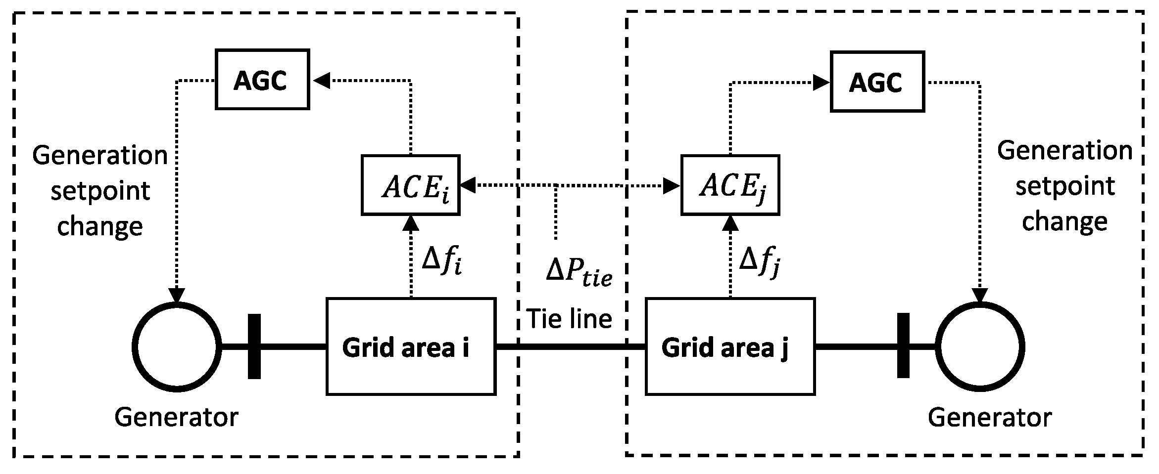
Most of the studies in literature on cyber-physical vulnerability of LFC focus on secondary control, and in particular on AGC. AGC is an automatic feedback control system in charge of driving to zero the frequency error in the control areas of the grid and driving to the scheduled values the power flows at the tie lines connecting the control areas. The focus on secondary control is not surprising, since it is an automatic control loop involving exchange of measurements and control signals over a telecommunication network. Figure 5 reports a simplified scheme of AGC, where, for simplicity, only two grid areas are shown, linked by a tie line, and hosting one generator each (load is not represented). AGC increases or decreases the active power generation setpoint in each area based on the computation of the area control error (ACE), which is in turn a function of the frequency deviation in the area and the deviation of the tie line power flow from the scheduled values. AGC is typically a proportional-integral controller.
To the best of our knowledge, attacks to AGC have been conceptualized and analysed first in [83], in the context of a two-area power system. In [83], the opponent disables the AGC of an area and replaces the AGC control signal with a disturbance signal. The two-area power system under attack is modelled as a nonlinear control system , where x is the vector of the state variables (area frequency errors, voltage angle difference at the end of the tie lines and AGC signal) and u the attack signal. Reachability theory is used to evaluate if there exist attacks able to drive the system out of a safety region K. For this, the set is computed as the set of initial states such that the evolution of the system from an initial time t to a final time T remains confined in the safety set, for every possible attack signal:
where is the state evolution at time , when the system is initialized at state x at time t, and control u is applied; is the space of admissible inputs. A successful attack at exists only if . can be computed [83] by evaluating the level sets of the following function:
where is the signed distance of x from the set K (i.e., it is zero if , and equal to otherwise). Then, can be computed as the zero-level set of V, that is, (notice from (21) that means that every trajectory starting from x remains in K). The attack assumes full model knowledge and disruption resources. Successful attacks exist depending on the disruption resources (i.e., the magnitude of the disturbance power injected).
In [84], the time-delay-switch attack to LFC is discussed. The attack introduces delays in the AGC feedback loop, and is modelled as a switching action between the conditions “off”, when no delay is injected, and “delay-by-”, where a delay of seconds is injected. The generic state space model of LFC in N power areas is presented, as , where X is the state vector (frequency deviations, generators power deviation, tie-line power flows, ACEs, etc.), U the LFC action, and load deviations in the areas. The system is controlled with an optimal feedback controller . Hence, the control action during attack is , where is the delayed state feedback and h is a step function to model the start of the attack at given time , that is, for and for . The attack makes LFC unstable. Results are reported for a 2-areas power system, showing that the area frequency, the generator power, and the tie-line power flow diverge as a result of the attack. A recent experimental evaluation of the impact of delays in the AGC loop has been carried out in [85], which also considers simultaneous physical line attacks, and their effect on voltage stability.
In a similar setting, reference [86] employs switched system theory to investigate the impact of DoS attacks on LFC. Under DoS, the measurements from the field cannot be transmitted to the control center, and it is assumed that the last available measurements are used. Therefore the optimal LFC controller can be stated as , where if (with denoting that there is no attack), and if (with denoting that DoS is performed). It is shown, in a 2-areas power system, that there exist switching sequences between and that destabilize system variables.
Reference [87] studies the effect of corrupting frequency and/or tie line power flow measurements used to compute the ACE, which determines the adjustments operated by AGC to keep frequency and tie line power flow regulated. It is assumed in [87] that the attack remains undetected by standard methods as long as the corrupted ACE signals remain below a given threshold. Two main attack scenarios are discussed: one, in which the aim is to cause significant frequency oscillations, leading to load shedding, and a second one, aimed at impacting the real time market, by altering the amount of power produced (and hence billed) in the different areas. The measurement corruption types studied are: scaling, ramp, pulse, and random attacks, in which, respectively, the measurement is corrupted with an additive factor, with a factor increasing in time, with a pulsating signal, and with a random signal. A detection and a resilient control strategy based on short-term load forecast is then presented to cope with such attacks. In [88] and references therein, it is proposed to pipeline SE with AGC: the ACE computation is fed by the estimation (i.e., not the direct measurement) of the frequency and tie line power flow. This makes harder to attack the AGC. Consecutive FDIAs on the power flow measurements, over multiple AGC cycles, are considered, until unsafe frequency deviations are caused (e.g., until remedial actions such as loads or generators disconnection are taken). Corruption of the frequency measurement is not considered, as it is easily detectable. A method is then proposed for computing the optimal attack sequence, that is, the one which minimizes a time-to-emergency metric, defined as the time from the attack start until when given safety frequency limits are violated. Finally, it is discussed how an attacker can learn the needed model parameters by active probing and passive monitoring (thus reducing the required model knowledge). Detection, identification and resilient control schemes are proposed.
Reference [89] introduces resonance attacks to LFC. The measurements of input variables to LFC are corrupted to cause instability of a controlled variable (the rate of change of frequency, which is input of the tripping relays). The effectiveness of the attack is tested in scenarios considering realistic and detailed models of the turbine-governor system (which are not included in the attack design).
Finally, an updated survey on the cyber-physical attacks to LFC, and possible detection and defense mechanisms, can be found in [90]. The survey focuses on replay attacks, FDIAs, DoS attacks, resonance attacks, and time delay attacks, mostly focusing on AGC.
3.9. Interdiction Attacks and Sequential Attacks
The attacks discussed in the previous sections are mostly based on data deception, that is, an attacker corrupts data flowing in the smart grid with the aim of causing disruption, for example, by causing the smart grid control systems and/or the operators to make wrong decisions based on the corrupted data. In this and the following sections, the analysis will move to cyber-physical attacks more directly targeting physical devices of the grid. In these cases, the attacker takes control of smart grid assets via a cyber-attack, and then operates them in a way to disrupt them and/or the grid.
Interdiction attacks are attacks in which network elements are interdicted (i.e., destroyed, put out of order) by the adversary. Among the first to study in depth this type of attack were Salmeron et al. in [91]. They propose a bi-level optimization model to find the attack plan that will result in the most damage. Such a bi-level model has since found numerous applications in the design of other attacks, as seen, for example, in Section 3.3 and Section 3.7. Reference [92] provides the optimal solution of the problem in [91] by transforming the original problem into an equivalent MILP problem. The study [93] is particularly relevant as it generalises the terrorist threat problem by allowing different objective functions in the inner and the outer problems and by allowing constraints in the outer problem to be also functions of the inner variables. Again, the bi-level problem can be reduced to a single level MILP one. The study [94] proposes a tri-level problem in which an additional defense layer is added on top to model the ex ante protection and reinforcement of the infrastructure by the operator. Finally, reference [95] introduces global Benders decomposition for solving large-scale, electric power grid interdiction problems. These papers are relevant for this study as they introduce techniques which have been used in the modelling of many cyber-physical attacks, as seen in the previous sections.
Sequential attacks are interdiction plans in which the temporal sequence of interdictions is carefully designed to maximise the damage (while the works just mentioned do not consider time dynamics but only the result of steady state OPF computation). They have been introduced and analysed by Zhu et al., for example, in [96,97], which show how they can lead to worst consequences than simultaneous attacks on the same set of lines. Several strategies (e.g., enumeration, heuristics, graph-based metrics) are proposed to choose the nodes and the order of the attacks. Finally, Ref. [98] proposes Q-Learning to find worst case sequential attacks (at each step, a positive reward is given to the Q-Learning agent if the current line interdiction results in disconnection of N lines after having attacked a total of less than N lines, i.e., if there is an amplification effect).
3.10. Switching Attacks
Coordinated switching attacks have been introduced in [99,100], where they are constructed by modelling the transmission system as a single machine infinite bus system, with one generator and one load connected to the bus via a breaker. The attacker finds a switching sequence for the breaker that makes the phase angle (i.e., the rotor angle) and the frequency of the generator unstable, forcing it to disconnect. The single machine infinite bus system is modeled as a linear switching system:
where , and are, respectively, the dynamics matrices modelling the system when the load is connected (i.e., when ) or disconnected (when ); is the switching rule (also called the switching surface). The state variables x are the generator phase angle and frequency.
The system is said to possess a sliding mode when the state trajectories are attracted and confined in a boundary of the switching surface . The necessary and sufficient condition for the existence of a sliding mode is reported in [99]. The paper develops a 4-step method to design linear switching rules that make (22) unstable. The method essentially consists in finding an unstable sliding mode for the system, by overlapping the two phase portraits of the switched system (22), and searching graphically for a switching curve such that the phase vector of the switched system points toward the curve (which means that the sliding mode condition is respected) and away from the origin (which means that the sliding mode is unstable). In [99], it is shown how the method can be adapted to work also in more realistic case studies.
In [101], the condition for the existence of a linear sliding mode , , is detailed. The general necessary and sufficient condition is or, equivalently, , which, by computing , with , is equivalent [101] to:
Reference [101] shows that (23) allows to generalise the method presented in [100] to find a feasible coordinated switching attack. Given the transmission network at study, a target attack switch is selected and the variable structure representation of the system for the open and the close switch position is found (i.e., for , and for ). The dynamics are then linearised to recover a representation in the form (22). Using condition (23), a linear switching surface is found such that the corresponding sliding mode is unstable and its region of attraction includes the operating point of the system at the beginning of the attack. A classification of the vulnerability of each switch is then proposed in [101], by considering the range of vectors C for which a successful attack exists. The authors of [99,100,101] consider single switch attacks, linear system models and switching surface. The attacker needs model knowledge, disruption resources, and disclosure resources (including the real time knowledge of the state of the system).
The above notions are rigorously formalized in [102], which also provides theorems with conditions to ascertain the existence of sliding modes and their stability properties. The work also considers the case of attackers with limited model knowledge (the results are applied on a model with parameters to capture modelling errors) and the case of limited disclosure resources (by analysing the case in which the rotor angle information is not directly available to the attacker and needs to be estimated). In [103], the analysis is extended to the multi-switch attack scenario, in which the opponent takes control of m of the total M switches in a grid (line switches, generators switches, etc.) and performs switching with the aim of causing transient instability of target generators. Accordingly, the switching rule is a m-dimensional vector. Linear switching is investigated, that is, , where are the state variables, given by the target generators’ frequency and phase angle. In this setting, an attacker can exploit both the individual sliding surfaces, , if they exist (the condition being again ), and also the overall sliding surface, , which exists if . Synchronized switching is investigated, in which the attacker controls the switches all according to the same switching rule (all the rows in C are equal), concurrent switching, where switches have different switching rules, and progressive switching, where switches are attacked in sequence (i.e., individual sliding modes are sequentially exploited). Attack construction methods are given. Realistic simulations show that feasible attacks exist even when the effect of the existing excitation and governor control of generators are considered (while they are not considered in the attack design, as the generators are modelled with the swing equation—i.e., (24) presented below—with no controls attached). Simulations focus on line switching, and a case study of a cascading attack is also presented. Finally, it is shown that the required switching times are compatible with the existing switching technology. Applying similar concepts, ref. [104] analyzes of an attacker performing a switching attack on an energy storage system (ESS), with the aim of destabilizing a target generator. This is relevant, given the ever increasing storage penetration in the grid (also considering electric vehicles, virtual storage, etc.).
Recently, in [105], the analysis of switching attacks in a nonlinear setting considers single switching, with a switching surface , with . The use of nonlinear switching surfaces results in faster successful conclusion of the attack and reduced chattering of the switches (the metrics “fastness of attack” and “swiftness of attack” are proposed).
The recent contribution [106] presents a methodology to evaluate the risk of switching attacks in substations based on today’s cybersecurity technologies.
Finally, an attack similar to the switching attack is the so called Aurora attack, targeting synchronous generators. An attacker takes control of a generator’s breaker, disconnects the generator from the grid, and then re-connects it when it is in out-of-phase with the grid. This can lead to physical damage to the generator, because of the resulting significant electromagnetic torque and current fluctuations in the generator. In [107], Arani et al. extend the original Aurora attack (discussed in reference [12] in [107]), to the case in which the attacker targets the breaker of the point of common coupling of a synchronous generator-based microgrid with the main grid. Based on the analysis of the synchronous generator’s swing equation (see (24)), it is shown in [107] that the angle deviation of the generators in the microgrid can be well approximated as , where is the mismatch of power generation and consumption in the microgrid, M the inertia of the generator, the duration of the attack (i.e., the time from the disconnection of the breaker at the point of common coupling, to its re-connection). From this equation, it is observed that the attacker needs to monitor , to make sure the attack is launched when there is a high power mismatch, which results in a significant out-of-phase breaker reclosing.
3.11. Load Altering Attacks
In load altering attacks (LAAs) [108], the consumption of targeted loads is modified, with the objective of causing line overloading. Both direct hacking of loads is discussed, as well as indirect load variation through the corruption of, for example, the price information broadcast to the consumers in the case of demand side management schemes. The loads more likely to be subject to LAAs are revised in [108], and a cost-efficient selection of the loads to protect in order to avoid circuit overflow is proposed.
In [109], dynamic load altering attack (DLAAs) are investigated, which go beyond the mere (abrupt) variation of load (static LAAs), by controlling the attacked load in closed loop fashion, proportionally to the sensed frequency variation. The linearised power flow equations are used to model the network constraints, and the linear swing equations to model the generators’ dynamics:
being i the generic generator, the rotor inertia, the frequency deviation at bus i, the mechanical power, the damping coefficient, the generated electrical power. The mechanical input to the generator is modeled as
in order to model the turbine governor (proportional controller) and the LFC (an integral controller—see also Section 3.8). Loads at each bus are then classified into three categories: (i) uncontrollable, (ii) controllable but frequency-insensitive, and (iii) controllable and frequency-sensitive [109]. The load pertaining to classes (i) and (ii) is denoted with . It is that is the target of the LAA, and it is assumed that a part of it is secured () and part vulnerable (). As anticipated above, the attack is finally modeled as:
The index denotes the attacked load bus, s denotes the sensor bus, that is, the bus from which the attacker gains a measurement of the frequency. It is either a generation bus or a load bus. is the frequency deviation at the generation bus s, the frequency deviation at the load bus s. () denotes the attacker gain in case the sensor bus is a generation (load) bus (only one of the two will be different from zero). By combining the above equations and the attack model, the following linear state-space descriptor representation of the system under attack is derived [109]:
As for the state variables, is the vector of voltage phase angles at the generation buses, is the vector of frequency deviations at the generation buses, is the vector of voltage phase angles at the load buses and is the vector of frequency deviations at the load buses. It is evident from (27) that the attack gain matrices and influence the system dynamics. Indeed, after transforming (27) into a standard state-space model, it is shown in [109], via Lyapunov analysis, that an appropriate selection of the attacked buses and of the attack gains can lead to frequency instability. Both the case in which a single load bus is attacked (single-point attack) and multiple ones are attacked (coordinated multi-point attacks) are investigated. A protection scheme is proposed to optimize the amount of load to be protected at the different buses in order to ensure the system remains stable under attack. In [110], an optimal attack model is presented to launch successive DLAAs against aggregators responsible for direct load control. In [111], a transactive energy framework is proposed to counteract ongoing LAAs aimed at destabilizing network frequency. Another defence approach is proposed in [112], where invariance theory and Lyapunov arguments are used to study the optimal placement and sizing of ESSs in the network, so as to make destabilizing DLAAs impossible (ESSs inject and adsorbe power to counteract the power fluctuations caused by DLAA).
Recently, in a similar setting as in [109] (i.e., (24)–(27)), Wu et al. discuss in [113] a FDIA which corrupts in an additive way the control (25), with a destabilizing effect on frequency. Optimal control theory is used to find the optimal attack in two cases: (i) when the attacker targets a fixed set of control channels, and (ii) when the attacker changes during time the attacked channels (i.e., an optimal switching sequence is found). The target function is designed to maximize the frequency deviations, while minimizing the magnitude of the attack signal.
Finally, a version of LAA, called load-changing attack, has been discussed by Arnaboldi et al. in [114] (and previously, e.g., in References [10,11] in [114]). In these works, the attacker takes control of a large number of power devices (e.g., household appliances, electric vehicles, etc.), and controls the power consumption of the formed botnet in order to disrupt the grid operation.
3.12. Zero Dynamics and Covert Attacks
The zero dynamics attacks are malicious control actions leveraging the internal structure of dynamical systems. The concept of zero dynamics was originally introduced in [115]: “a dynamical system that characterizes the internal behavior of a system once initial conditions and inputs are chosen so as to constrain the output to be identically zero”.
The topic of zero dynamics attacks is mainly discussed in [25,26,28,116,117]. The possibility of realizing this kind of attack arises from the consideration that, as shown, for example, in [116], it is possible to inject signals in a system that make the internal state diverge, while the effects of such attack are not visible from the mere observation of the output, which in turn can be arbitrarily stabilized using an (output feedback) control.
A typical scenario, presented in [25,26], considers a power network which interconnects power plants operated by different generation companies competing on the market. Some companies form a coalition aimed at damaging the remaining power plants in the network, while still operating most of their power plants correctly. To this purpose, the prime mover governors of the power plants are used as attack controllers in order to destabilize the state of the target machines, representing the zero dynamics of the system, and decouple it from the state of the coalition, viewed by the attacker as the system output. This result is achieved at the cost of sacrificing one generator of the coalition.
In general terms, the attack is achieved provided that a pair of independent controls are available to the attacker. A first control is used in order to force the state subspace related to the zero dynamics to be a controlled invariant; then a second control is applied in order to destabilize them. The attack, originally presented in [25,26] using the machinery of geometric control theory, is formally summarized in the following using arguments similar to those reported in [118]. Consider a system of the form
with denotes the state of the plant, and are the controls available to the attacker, represents an output the attacker is interested to regulate. To simplify the presentation, consider the case in which
where for , that is, the case in which system (28), viewed by the attacker as a system with input and output , has vector relative degree and a diagonal “high-frequency gain matrix”. This, in fact, is the case in which system (28) models the small-signal electromechanical behaviour of a power network, consisting in the interconnection of a set of identical power plants, all of them independently actuated. Nevertheless, the theory can be easily extended to other class of systems having a generic vector relative degree . It is also assumed that
which is another feature of the class of systems at study. As it is well known, under these assumptions, there exists a change of variables that puts system (28) in the normal form
in which
and , , . With this in mind, the zero dynamics attack can be performed through the following two steps. Since the target of the attack are the zero dynamics, at first the control is designed so as to decouple the system output from the dynamics under attack and, eventually, to assign any prescribed stable dynamics on . This is achieved by means of the control
in which , , and , where the matrices , for , are Hurwitz. Having rendered the zero dynamics unobservable through the output , the control is consequently chosen so as to let them diverge. Assuming the pair is controllable and z is available for measurement, the residual attack can be chosen as
so as to assign eigenvalues with positive real parts to the matrix . Finally, the combination of controls (32) and (33) forces a closed loop system of the form
characterized by antistable zero dynamics which are not visible from the mere observation of the system output.
In case of application of the attack to a power system, the model (28) takes the form
where and denote the vectors of machines rotor angles and angular speed deviations from synchronism, is the vector of mechanical input power (whose only coalition’s components are considered active), the matrices M and D model the inertia and damping coefficients of the coalition’s machines, and are identity matrices; finally , , and are properly sized submatrices of the network Laplacian matrix. The model describes the small-signal electromechanical behaviour of an unregulated power system, under the effect of deviations in the mechanical power of coalition’s power plants with respect to the steady-state values.
It is straightforward to see that model (35) is already in the form (31): the state partition represents the rotor angles and speed deviations of the generators making part of the coalition, while the state partition z represents the same variables of the target generators and the sacrificial one. The control of the sacrificial generator is used to destabilize the zero dynamics, while the other controls available to the coalition are used to stabilize their dynamics. This results in a portion of the network (the generators of the coalition minus the sacrificial one) to work properly, decoupled under feedback from the destabilized part of the network.
The attack reported above assumes the presence of an omniscient attacker, having full knowledge about the structure and parameters of the plant model and availability of measurements about the state partition under attack [26]. In [116] it is shown how to overcome these limitations designing a zero dynamics attack that, making use of a robust disturbance observer presented in [119], is robust in spite of model uncertainties. Several works can be found in the literature aimed at detecting the zero dynamics attacks: the most relevant approaches are based on the design of centralized and decentralized observers [25], adaptive sliding mode observers [120], Kalman filter [121], or works by properly altering the input behaviour of the plant [122].
Finally, it is interesting to note that the arguments used above to formally introduce the attack can be applied also in the context of a defence strategy. Indeed, a scenario can be conceived in which the output of model (28) represents a set of variables to be protected against the spread of an attack affecting the zero dynamics. In this regard in [118] a robust defence scheme is proposed, which makes the dynamics of a selected set of power plants decoupled from the dynamics of the subsystem targeted by the attack, with the aid of an extended high-gain observer [123,124], used to robustify the control (32) in spite of inaccurate knowledge of model parameters and lack of state measurements.
3.13. Attacks against Automatic Voltage Control
Several contributions in literature discuss cyber physical attacks on the grid voltage control schemes. Among the first works, Ref. [125] discusses data integrity attacks to voltage control in transmission networks, aimed at altering the settings of the flexible alternating current transmission system (FACTS), which are electronic-based devices (series compensation, static var compensator, static synchronous compensator (STATCOM), synchronous condenser, mechanically switched capacitors, etc.) installed at critical points of the grid, and responsible of several tasks (increased power transfer, damping of oscillations, etc.), including voltage control. A simple sensitivity analysis is presented in [125], to determine the FACTS to attack to cause the highest voltage disruption. In [126], a simulation study is provided on the impact of bias injection attacks on voltage support devices (voltage source converters and STATCOM) in transmission grids. The attacker injects a bias into the bus voltage measurement taken by the devices. The impact on transient angle and voltage stability is quantitatively assessed, with reference to two stability indicators. Simulations show that an attack could cause system instability after a contingency, hence making the system in-compliant.
In [127], Teixeira et al. discuss FDIAs on voltage measurements in the Volt-VAR control in distribution networks, discussing the undetectability conditions, and the impact in terms of increased network losses. The recent paper [128] presents a FDIA scheme against OPF-based AVC in distribution networks (generally speaking, an OPF is solved to determine the optimal feeders’ voltage profiles to minimize network losses). The voltage measurements sent from the substations to the control center are corrupted through an RL strategy that requires minimal model knowledge. Specifically, the FDIA targets the SE module in the control center (where the OPF is solved), which feeds the OPF problem for losses minimization. The reward of the RL agent is proportional to the voltage deviation caused at the buses. The method is effective in selecting the most critical bus and time of the attack to cause the worst voltage violations, or collapse. A detection and correction SE method is proposed to replace the suspect values with a maximum likelihood estimation derived from historical data.
In [129], a data integrity attack scheme against centralised voltage control in active distribution grids hosting photovoltaic (PV) generation is discussed. The attacker falsifies the voltage readings from the field, which are used to centrally determine the optimal positions of the transformers’ tap changers. Optimal undetectable attacks are designed, to cause maximal voltage violations at network nodes. It is shown also that, inducing over-voltages can lead PV plants to curtail their power output, causing significant economic losses (renewable generation along medium voltage feeders generally increases voltage levels, and for this reason PV plants can be equipped with power conditioning systems, which reduce the PV output in case of over-voltages, to contribute to voltage control).
More recently, in [130], Cameron et al. discuss the impact of DoS against voltage control in distribution grids. They experimentally evaluate the impact of burst, sequential and continuous low rate DoS, considering both static and adaptive approaches (in the adaptive DoS, the attacker dynamically adjusts the attack based on the response of the defender). A commonly adopted three-layers multi agent architecture for voltage control in distribution networks is considered, where the lower level is the customer level, typically formed by smart meters and distributed generation; the middle layer is composed of local controllers and data collection components; the top layer refers to a central server for processing global data and control objectives. It is shown the effectiveness of turning the above three-layer static architecture into a multi-agent reconfigurable one, more resilient to the analysed attacks.
In [131], Teixeira et al. discuss attacks on voltage droop control schemes in inverter-based microgrids. The attacks discussed include reference signals attack, in which the voltage setpoint of the control loop is altered, and voltage measurement routing attack, in which a given measurement is redirected from the original sensing channel to another one. The effects are quantitatively evaluated based on the theory of positive systems.
In [132], Ghafouri et al. propose a FDIA attack on PMU-based voltage stability monitoring in transmission networks. The attack is built based on the computation of the power flow equations, and hence is stealthy to standard detectors. Detection and mitigation strategies are proposed.
3.14. Other Cyber-Physical Attacks
This section presents a brief overview of other relevant contributions in literature addressing aspects of cyber-physical security of the smart grid. Reference [133] discusses time synchronization attacks, in which the temporal alignment of the measurements collected from the grid is disrupted. The case of time synchronization via GPS signal in PMUs is considered, and the effects of an attack breaking synchronization (e.g., via GPS spoofing) in three relevant applications (transmission line fault detection/locationing, voltage stability monitoring and event locationing) are discussed. Reference [134] discusses the issue of pricing attacks to home energy management systems, which is gaining more and more relevance in the context of active demand applications. In [135], attacks against emulated inertia control are explored. Emulated inertia refers to the control of inverter-connected devices with the aim of emulating the dynamics of the rotating inertia traditionally provided by the synchronous generators. The aim of the attacker is to cause frequency oscillations that trip a set of target generators.
4. Discussion and Ongoing Research Directions
The works on FDIA against SE, revised in Section 3.2, have started and shaped much of the research in the field. They have also often prompted the formulation of specific and basic research questions and problems (e.g., the formulation of detectability and identifiability conditions, the formulation of undetectable, sparse and maximal impacting attacks, etc.), which have been addressed by a number of methodological papers from the system theory and automatic control research community (a selection of these works has been revised in Section 2). As a matter of fact, system theory provides fundamental tools to model the smart grid as a cyber-physical system, to model and analyse cyber-physical attacks, and to evaluate their impact on the smart grid.
The analysis of cyber-physical attacks, their working principles and their dynamics, has a key importance for improving the security of the smart grid. It allows to discover new vulnerabilities, and it can guide the process of strengthening the smart grid towards a more robust and resilient system.
Several considerations can be done based on the works revised in this survey. First of all, most of the early works, and the works introducing new attack schemes, perform the design and the analysis of the attacks based on strong assumptions on the attacker’s resources, in terms of model knowledge, disruption, and disclosure resources. Even though in many cases these assumptions are too strong, considering the current state of the art, such analysis are fundamental, especially in a risk-analysis perspective [27], since they allow presenting the new vulnerability in a clear and simple setting, and they allow evaluating the worst-case possible impact of the attack. As seen in the review, the strong assumptions characterizing the first works are then progressively removed in the later works, which present attack formulations in a range of risk scenarios characterized by reduced/no model knowledge, disclosure, and disruption resources. In risk analysis terms, the greater the resources assumed for the attacker, the higher is the resulting impact of the attack, and the lower the likelihood associated with the risk scenario.
A second aspect worth to highlight is that most of the works in the field, and especially the early ones, focus on the transmission sector, since its disruption causes significantly larger impact than the distribution and the consumption sectors. A second reason is also due to the fact that, until recently, the consumption and the distribution were passive sectors of the grid. However, with the recent transition towards an active grid and the spread of distributed energy resources and connected devices at distribution and consumption levels (smart home devices, electric vehicles, storage, etc.), the interest is greatly increasing also in investigating cyber-physical vulnerabilities at these levels.
A third aspect is related with the increase in sophistication of the attack schemes studied. Most of the early works consider the disruption arising from the implementation by the attacker of a single type of disruption action, which, in most of the cases, consists in the injection of malicious data into sensing or actuating channels (e.g., the FDIAs reviewed in Section 3.2). More recently, complex, coordinated cyber-physical attacks are more and more being studied, in which different attack types are combined together, in different steps, typically through multi-level optimization problems, also capturing the attacker-defender interactions (see, e.g., Section 3.3 and Section 3.4.1).
Finally, regarding the attack mechanisms, at least two categories of works can be distinguished. In some works, the attack results from the injection of false data into the smart grid systems, which misleads the smart grid control systems and/or the operator to assume a false state of the grid, leading to wrong control actions (e.g., Section 3.2). In other works instead, the disruption results from the attacker targeting key components of the grid, and operating them in a way that causes disruption (e.g., grid instability, Section 3.9–Section 3.11).
Other research trends in the area include:
- A deeper understanding and analysis of known vulnerabilities and attack types, to evaluate to which extent attacks already documented in the literature can be formulated by relaxing assumptions on the attack model. It is normally the case in fact that, for the discovery and the first analysis of new vulnerabilities, researchers assume very broad and strong model knowledge and disclosure/disruption resources for attacker. For example, some works in literature have been discussed which use machine learning approaches, or tools from adaptive and robust control, to design attacks requiring reduced model knowledge and/or attack resources;
- Integration of more accurate models of the system under attack. It is often the case in fact that the early attack analysis are performed on simplified models, for example, typically on linearized models (e.g., DC models), while it is known that most of the smart grid systems are complex, nonlinear systems. The analysis with nonlinear (or, more in general, more detailed system models) is more complex, but could bring additional insights as well (as discussed for example for the case of FDIAs against SE and switching attacks).
- Combining attack models to generate complex, coordinated multi point-attacks. Concepts and tools used in the design of a given attack often find applications in the design of new attacks. As the analysis of known attacks reveals, in real, complex scenarios, different attack types can be combined with the aim of, for example, amplifying disruption, delaying the attack detection/identification, delaying response, mitigation and service restoration, and so forth.
5. Conclusions
This paper has presented a review of the state of the art in the design of cyber-physical attacks targeting the smart grid. This is one of the most active research areas in the field of cyber-physical security, given the criticality for our society of the electrical infrastructure and the increased number of vulnerabilities introduced by the ongoing smart grid digitalization and decentralization process. This paper adopted a system theoretic point of view in the analysis, with the objective of presenting the fundamental, inner working principles of the attacks, which in turn depend on the properties and the dynamics of the attacked system. 4Several known attack categories in literature have been discussed, including a focus on models, attack dynamics and impacts, which are mainly divided into economical and physical disruption impacts, including maximizing generation cost, the load shedding cost, the network losses, manipulating market prices to generate undue financial revenues in electricity markets, and, on the physical disruption side, creating transmission line overload, tripping of generators, violation of voltage limits, voltage, frequency and rotor angle instability, operation of the system in an in-compliant security state, and so forth. Finally, current trends of research in the area have been briefly discussed.
Author Contributions
F.L. contributed to the conceptualization of the paper and elaborated all the sections, except Section 3.12. E.G. contributed to the conceptualization of the paper, to Section 2, and revised the entire paper. A.D.G. elaborated Section 3.12 and revised the entire paper. All authors have read and agreed to the published version of the manuscript.
Funding
This research received no external funding.
Acknowledgments
The authors thank the reviewers for the fruitful comments made.
Conflicts of Interest
The authors declare no conflict of interest.
Abbreviations
The following abbreviations are used in this manuscript:
| AC | Alternating current |
| ACE | Area control error |
| AGC | Automatic generation control |
| AVC | Automatic voltage control |
| BDD | Bad data detection |
| CPS | Cyber-physical system |
| DC | Direct current |
| DoS | Denial of service |
| DLAA | Dynamic load altering attack |
| EMS | Energy management system |
| ESS | Energy storage system |
| FACTS | Flexible alternating current transmission system |
| FDIA | False data injection attack |
| GPS | Global positioning system |
| KKT | Karush–Kuhn–Tucker |
| LAA | Load altering attack |
| LFC | Load frequency control |
| LMP | Locational marginal price |
| LR | Load redistribution |
| MILP | Mixed integer linear programming |
| PV | Photovoltaic |
| PMU | Phasor measurement unit |
| PJM | Pennsylvania-New Jersey-Maryland |
| RAS | Remedial action scheme |
| RL | Reinforcement learning |
| SCADA | Supervisory control and data acquisition |
| SCED | Security-constrained economic dispatch |
| SE | State estimation |
| STATCOM | Static synchronous compensator |
| TA | Topology attack |
References
- Lee, E.A. Cyber physical systems: Design challenges. In Proceedings of the 2008 11th IEEE International Symposium on Object and Component-Oriented Real-Time Distributed Computing (ISORC), Orlando, FL, USA, 5–7 May 2008; pp. 363–369. [Google Scholar]
- Mrabet, Z.E.; Kaabouch, N.; Ghazi, H.E.; Ghazi, H.E. Cyber-security in smart grid: Survey and challenges. Comput. Electr. Eng. 2018, 67, 469–482. [Google Scholar] [CrossRef] [Green Version]
- He, H.; Yan, J. Cyber-physical attacks and defences in the smart grid: A survey. IET-Cyber-Phys. Syst. Theory Appl. 2016, 1, 13–27. [Google Scholar] [CrossRef] [Green Version]
- Sun, C.C.; Liu, C.C.; Xie, J. Cyber-physical system security of a power grid: State-of-the-art. Electronics 2016, 5, 40. [Google Scholar] [CrossRef] [Green Version]
- Pandey, R.K.; Misra, M. Cyber security threats—Smart grid infrastructure. In Proceedings of the 2016 National Power Systems Conference (NPSC), Bhubaneswar, India, 19–21 December 2016; pp. 1–6. [Google Scholar]
- Ashok, A.; Govindarasu, M.; Wang, J. Cyber-physical attack-resilient wide-area monitoring, protection, and control for the power grid. Proc. IEEE 2017, 105, 1389–1407. [Google Scholar] [CrossRef]
- Sun, C.C.; Hahn, A.; Liu, C.C. Cyber security of a power grid: State-of-the-art. Int. J. Electr. Power Energy Syst. 2018, 99, 45–56. [Google Scholar] [CrossRef]
- Otuoze, A.O.; Mustafa, M.W.; Larik, R.M. Smart grids security challenges: Classification by sources of threats. J. Electr. Syst. Inf. Technol. 2018, 5, 468–483. [Google Scholar] [CrossRef]
- Wadhawan, Y.; AlMajali, A.; Neuman, C. A comprehensive analysis of smart grid systems against cyber-physical attacks. Electronics 2018, 7, 249. [Google Scholar] [CrossRef] [Green Version]
- Weerakkody, S.; Sinopoli, B. Challenges and opportunities: Cyber-physical security in the smart grid. In Smart Grid Control; Springer: Berlin/Heidelberg, Germany, 2019; pp. 257–273. [Google Scholar]
- Gusrialdi, A.; Qu, Z. Smart grid security: Attacks and defenses. In Smart Grid Control; Springer: Berlin/Heidelberg, Germany, 2019; pp. 199–223. [Google Scholar]
- Lun, Y.Z.; D’Innocenzo, A.; Smarra, F.; Malavolta, I.; Di Benedetto, M.D. State of the art of cyber-physical systems security: An automatic control perspective. J. Syst. Softw. 2019, 149, 174–216. [Google Scholar]
- Ding, D.; Han, Q.L.; Xiang, Y.; Ge, X.; Zhang, X.M. A survey on security control and attack detection for industrial cyber-physical systems. Neurocomputing 2018, 275, 1674–1683. [Google Scholar] [CrossRef]
- Aoufi, S.; Derhab, A.; Guerroumi, M. Survey of false data injection in smart power grid: Attacks, countermeasures and challenges. J. Inf. Secur. Appl. 2020, 54, 102518. [Google Scholar] [CrossRef]
- Zhang, H.; Liu, B.; Wu, H. Smart Grid Cyber-Physical Attack and Defense: A Review. IEEE Access 2021, 9, 29641–29659. [Google Scholar] [CrossRef]
- Zografopoulos, I.; Ospina, J.; Liu, X.; Konstantinou, C. Cyber-physical energy systems security: Threat modeling, risk assessment, resources, metrics, and case studies. IEEE Access 2021, 9, 29775–29818. [Google Scholar] [CrossRef]
- Giani, A.; Sastry, S.; Johansson, K.H.; Sandberg, H. The VIKING project: An initiative on resilient control of power networks. In Proceedings of the 2009 2nd International Symposium on Resilient Control Systems, Idaho Falls, ID, USA, 11–13 August 2009; pp. 31–35. [Google Scholar]
- SPEAR Website. Available online: https://cordis.europa.eu/project/id/787011 (accessed on 21 August 2020).
- ENERGY SHIELD Website. Available online: https://cordis.europa.eu/project/id/832907 (accessed on 21 August 2020).
- PHOENIX Website. Available online: https://cordis.europa.eu/project/id/832989 (accessed on 21 August 2020).
- DEFENDER Website. Available online: https://cordis.europa.eu/project/id/740898 (accessed on 21 August 2020).
- SDNmicroSENSE Website. Available online: https://cordis.europa.eu/project/id/833955 (accessed on 21 August 2020).
- SUCCESS Website. Available online: https://cordis.europa.eu/project/id/700416 (accessed on 21 August 2020).
- Pasqualetti, F.; Dörfler, F.; Bullo, F. Cyber-physical attacks in power networks: Models, fundamental limitations and monitor design. In Proceedings of the 2011 50th IEEE Conference on Decision and Control and European Control Conference, Orlando, FL, USA, 12–15 December 2011; pp. 2195–2201. [Google Scholar] [CrossRef] [Green Version]
- Pasqualetti, F.; Dörfler, F.; Bullo, F. Attack Detection and Identification in Cyber-Physical Systems. IEEE Trans. Autom. Control 2013, 58, 2715–2729. [Google Scholar] [CrossRef] [Green Version]
- Pasqualetti, F.; Dorfler, F.; Bullo, F. Control-Theoretic Methods for Cyberphysical Security: Geometric Principles for Optimal Cross-Layer Resilient Control Systems. IEEE Control. Syst. Mag. 2015, 35, 110–127. [Google Scholar] [CrossRef]
- Chong, M.S.; Sandberg, H.; Teixeira, A.M.H. A Tutorial Introduction to Security and Privacy for Cyber-Physical Systems. In Proceedings of the 2019 18th European Control Conference (ECC), Naples, Italy, 25–28 June 2019; pp. 968–978. [Google Scholar] [CrossRef]
- Teixeira, A.; Shames, I.; Sandberg, H.; Johansson, K.H. A secure control framework for resource-limited adversaries. Automatica 2015, 51, 135–148. [Google Scholar] [CrossRef] [Green Version]
- Smith, R.S. A Decoupled Feedback Structure for Covertly Appropriating Networked Control Systems. IFAC Proc. Vol. 2011, 44, 90–95. [Google Scholar] [CrossRef] [Green Version]
- Amin, S.; Cárdenas, A.A.; Sastry, S.S. Safe and secure networked control systems under denial-of-service attacks. In International Workshop on Hybrid Systems: Computation and Control; Springer: Berlin/Heidelberg, Germany, 2009; pp. 31–45. [Google Scholar]
- Mo, Y.; Sinopoli, B. Secure control against replay attacks. In Proceedings of the 2009 47th Annual Allerton Conference on Communication, Control, and Computing (Allerton), Allerton House, IL, USA, 30 September–2 October 2009; pp. 911–918. [Google Scholar] [CrossRef] [Green Version]
- Kundur, P.; Balu, N.J.; Lauby, M.G. Power System Stability and Control; McGraw-Hill: New York, NY, USA, 1994; Volume 7. [Google Scholar]
- Abur, A.; Exposito, A.G. Power System State Estimation: Theory and Implementation; CRC Press: Boca Raton, FL, USA, 2004. [Google Scholar]
- Liu, Y.; Ning, P.; Reiter, M. False data injection attacks against state estimation in electric power grids. In Proceedings of the CCS’09 16th ACM Conference on Computer and Communications Security, Chicago, IL, USA, 9–13 November 2009; pp. 21–32. [Google Scholar] [CrossRef]
- Liu, Y.; Ning, P.; Reiter, M.K. False Data Injection Attacks Against State Estimation in Electric Power Grids. ACM Trans. Inf. Syst. Secur. 2011, 14, 13:1–13:33. [Google Scholar] [CrossRef]
- Rahman, M.A.; Mohsenian-Rad, H. False data injection attacks against nonlinear state estimation in smart power grids. In Proceedings of the 2013 IEEE Power Energy Society General Meeting, Vancouver, BC, Canada, 21–25 July 2013; pp. 1–5. [Google Scholar] [CrossRef]
- Kosut, O.; Jia, L.; Thomas, R.J.; Tong, L. Malicious Data Attacks on the Smart Grid. IEEE Trans. Smart Grid 2011, 2, 645–658. [Google Scholar] [CrossRef] [Green Version]
- Deng, R.; Xiao, G.; Lu, R.; Liang, H.; Vasilakos, A.V. False data injection on state estimation in power systems—Attacks, impacts, and defense: A survey. IEEE Trans. Ind. Inform. 2016, 13, 411–423. [Google Scholar] [CrossRef]
- Liu, T.; Sun, Y.; Liu, Y.; Gui, Y.; Zhao, Y.; Wang, D.; Shen, C. Abnormal traffic-indexed state estimation: A cyber–physical fusion approach for smart grid attack detection. Future Gener. Comput. Syst. 2015, 49, 94–103. [Google Scholar] [CrossRef]
- Haider, A.; Khan, M.A.; Rehman, A.; Rahman, M.U.; Kim, H.S. A Real-Time Sequential Deep Extreme Learning Machine Cybersecurity Intrusion Detection System. CMC-Comput. Mater. Contin. 2021, 66, 1785–1798. [Google Scholar] [CrossRef]
- Kim, J.; Tong, L. On Topology Attack of a Smart Grid: Undetectable Attacks and Countermeasures. IEEE J. Sel. Areas Commun. 2013, 31, 1294–1305. [Google Scholar] [CrossRef]
- Giani, A.; Bitar, E.; Garcia, M.; McQueen, M.; Khargonekar, P.; Poolla, K. Smart Grid Data Integrity Attacks. IEEE Trans. Smart Grid 2013, 4, 1244–1253. [Google Scholar] [CrossRef]
- Zhang, J.; Chu, Z.; Sankar, L.; Kosut, O. False data injection attacks on phasor measurements that bypass low-rank decomposition. In Proceedings of the 2017 IEEE International Conference on Smart Grid Communications (SmartGridComm), Dresden, Germany, 23–26 October 2017; pp. 96–101. [Google Scholar] [CrossRef] [Green Version]
- Yang, Q.; Chang, L.; Yu, W. On false data injection attacks against Kalman filtering in power system dynamic state estimation. Secur. Commun. Netw. 2016, 9, 833–849. [Google Scholar] [CrossRef]
- Karimipour, H.; Dinavahi, V. On false data injection attack against dynamic state estimation on smart power grids. In Proceedings of the 2017 IEEE International Conference on Smart Energy Grid Engineering (SEGE), Oshawa, ON, Canada, 14–17 August 2017; pp. 388–393. [Google Scholar]
- Nath, S.; Akingeneye, I.; Wu, J.; Han, Z. Quickest detection of false data injection attacks in smart grid with dynamic models. IEEE J. Emerg. Sel. Top. Power Electron. 2019. [Google Scholar] [CrossRef]
- Song, Y.; Liu, X.; Li, Z.; Shahidehpour, M.; Li, Z. Intelligent data attacks against power systems using incomplete network information: A review. J. Mod. Power Syst. Clean Energy 2018, 6, 630–641. [Google Scholar] [CrossRef] [Green Version]
- Cao, Y.; Li, Y.; Liu, X.; Rehtanz, C. Local False Data Injection Attacks with Incomplete Network Information. In Cyber-Physical Energy and Power Systems; Springer: Berlin/Heidelberg, Germany, 2020; pp. 177–199. [Google Scholar]
- Zhang, J.; Chu, Z.; Sankar, L.; Kosut, O. Can Attackers with Limited Information Exploit Historical Data to Mount Successful False Data Injection Attacks on Power Systems? IEEE Trans. Power Syst. 2018, 33, 4775–4786. [Google Scholar] [CrossRef] [Green Version]
- Li, Q.; Cui, D.; Liu, M. Data-Driven False Data Injection Attacks on State Estimation in Smart Grid. In Proceedings of the 2018 37th Chinese Control Conference (CCC), Wuhan, China, 25–27 July 2018; pp. 6190–6195. [Google Scholar]
- Tian, J.; Wang, B.; Li, X. Data-driven and low-sparsity false data injection attacks in smart grid. Secur. Commun. Netw. 2018, 2018, 8045909. [Google Scholar] [CrossRef]
- Hug, G.; Giampapa, J.A. Vulnerability assessment of AC state estimation with respect to false data injection cyber-attacks. IEEE Trans. Smart Grid 2012, 3, 1362–1370. [Google Scholar] [CrossRef] [Green Version]
- Jin, M.; Lavaei, J.; Johansson, K.H. Power grid AC-based state estimation: Vulnerability analysis against cyber attacks. IEEE Trans. Autom. Control 2018, 64, 1784–1799. [Google Scholar] [CrossRef]
- Liu, X.; Li, Z. False Data Attacks Against AC State Estimation with Incomplete Network Information. IEEE Trans. Smart Grid 2017, 8, 2239–2248. [Google Scholar] [CrossRef]
- Nayak, J.; Al-Anbagi, I. Modelling False Data Injection Attacks Against Non-linear State Estimation in AC Power Systems. In Proceedings of the 2020 8th International Conference on Smart Grid (icSmartGrid), Paris, France, 17–19 June 2020; pp. 37–42. [Google Scholar]
- Yang, Q.; Jiang, L.; Hao, W.; Zhou, B.; Yang, P.; Lv, Z. PMU placement in electric transmission networks for reliable state estimation against false data injection attacks. IEEE Internet Things J. 2017, 4, 1978–1986. [Google Scholar] [CrossRef] [Green Version]
- Alexopoulos, T.A.; Korres, G.N.; Manousakis, N.M. Complementarity reformulations for false data injection attacks on PMU-only state estimation. Electr. Power Syst. Res. 2020, 189, 106796. [Google Scholar] [CrossRef]
- Ayad, A.; Farag, H.; Youssef, A.; El-Saadany, E. Cyber–physical attacks on power distribution systems. IET Cyber-Phys. Syst. Theory Appl. 2020, 5, 218–225. [Google Scholar] [CrossRef]
- Bhattar, P.L.; Pindoriya, N.M.; Sharma, A. A combined survey on distribution system state estimation and false data injection in cyber-physical power distribution networks. IET-Cyber-Phys. Syst. Theory Appl. 2021. [Google Scholar] [CrossRef]
- Primadianto, A.; Lu, C.N. A review on distribution system state estimation. IEEE Trans. Power Syst. 2016, 32, 3875–3883. [Google Scholar] [CrossRef]
- Yuan, Y.; Li, Z.; Ren, K. Quantitative Analysis of Load Redistribution Attacks in Power Systems. IEEE Trans. Parallel Distrib. Syst. 2012, 23, 1731–1738. [Google Scholar] [CrossRef]
- Yang, L.; Zhang, X.; Li, Z.; Li, Z.; He, Y. Detecting Bi-level False Data Injection Attack Based on Time Series Analysis Method in Smart Grid. Comput. Secur. 2020, 96, 101899. [Google Scholar] [CrossRef]
- He, H.; Huang, S.; Liu, Y.; Zhang, T. A tri-level optimization model for power grid defense with the consideration of post-allocated DGs against coordinated cyber-physical attacks. Int. J. Electr. Power Energy Syst. 2021, 130, 106903. [Google Scholar] [CrossRef]
- Pan, K.; Teixeira, A.; Cvetkovic, M.; Palensky, P. Cyber risk analysis of combined data attacks against power system state estimation. IEEE Trans. Smart Grid 2018, 10, 3044–3056. [Google Scholar] [CrossRef] [Green Version]
- Liang, G.; Weller, S.R.; Zhao, J.; Luo, F.; Dong, Z.Y. A Framework for Cyber-topology Attacks: Line-switching and New Attack Scenarios. IEEE Trans. Smart Grid 2017, 10, 1704–1712. [Google Scholar] [CrossRef]
- Liu, X.; Li, Z.; Liu, X.; Li, Z. Masking Transmission Line Outages via False Data Injection Attacks. IEEE Trans. Inf. Forensics Secur. 2016, 11, 1592–1602. [Google Scholar] [CrossRef]
- Chung, H.; Li, W.; Yuen, C.; Chung, W.; Zhang, Y.; Wen, C. Local Cyber-Physical Attack for Masking Line Outage and Topology Attack in Smart Grid. IEEE Trans. Smart Grid 2018, 10, 4577–4588. [Google Scholar] [CrossRef] [Green Version]
- Wang, Z.; He, H.; Wan, Z.; Sun, Y.L. Coordinated Topology Attacks in Smart Grid Using Deep Reinforcement Learning. IEEE Trans. Ind. Inform. 2020, 17, 1407–1415. [Google Scholar] [CrossRef]
- Tian, J.; Wang, B.; Li, T.; Shang, F.; Cao, K. Coordinated cyber-physical attacks considering DoS attacks in power systems. Int. J. Robust Nonlinear Control 2020, 30, 4345–4358. [Google Scholar] [CrossRef]
- Liu, X.; Li, Z. Local Topology Attacks in Smart Grids. IEEE Trans. Smart Grid 2017, 8, 2617–2626. [Google Scholar] [CrossRef]
- Jiongcong, C.; Liang, G.; Zexiang, C.; Chunchao, H.; Yan, X.; Fengji, L.; Junhua, Z. Impact analysis of false data injection attacks on power system static security assessment. J. Mod. Power Syst. Clean Energy 2016, 4, 496–505. [Google Scholar]
- Kang, J.; Joo, I.; Choi, D. False Data Injection Attacks on Contingency Analysis: Attack Strategies and Impact Assessment. IEEE Access 2018, 6, 8841–8851. [Google Scholar] [CrossRef]
- Khanna, K.; Panigrahi, B.K.; Joshi, A. Bi-level modelling of false data injection attacks on security constrained optimal power flow. IET Gener. Transm. Distrib. 2017, 11, 3586–3593. [Google Scholar] [CrossRef] [Green Version]
- Basumallik, S.; Eftekharnejad, S.; Johnson, B.K. The impact of false data injection attacks against remedial action schemes. Int. J. Electr. Power Energy Syst. 2020, 123, 106225. [Google Scholar] [CrossRef]
- Jahromi, A.A.; Kemmeugne, A.; Kundur, D.; Haddadi, A. Cyber-Physical Attacks Targeting Communication-Assisted Protection Schemes. IEEE Trans. Power Syst. 2020, 35, 440–450. [Google Scholar] [CrossRef]
- Zou, T.; Bretas, A.S.; Ruben, C.; Dhulipala, S.C.; Bretas, N. Smart grids cyber-physical security: Parameter correction model against unbalanced false data injection attacks. Electr. Power Syst. Res. 2020, 187, 106490. [Google Scholar] [CrossRef]
- Bretas, A.S.; Bretas, N.G.; Carvalho, B.E. Further contributions to smart grids cyber-physical security as a malicious data attack: Proof and properties of the parameter error spreading out to the measurements and a relaxed correction model. Int. J. Electr. Power Energy Syst. 2019, 104, 43–51. [Google Scholar] [CrossRef]
- Liu, C.; Liang, H.; Chen, T. Network Parameter Coordinated False Data Injection Attacks against Power System AC State Estimation. IEEE Trans. Smart Grid 2020. [Google Scholar] [CrossRef]
- Xie, L.; Mo, Y.; Sinopoli, B. Integrity Data Attacks in Power Market Operations. IEEE Trans. Smart Grid 2011, 2, 659–666. [Google Scholar] [CrossRef]
- Mengis, M.R.; Tajer, A. Data injection attacks on electricity markets by limited adversaries: Worst-case robustness. IEEE Trans. Smart Grid 2017, 9, 5710–5720. [Google Scholar] [CrossRef]
- Ahmadian, S.; Tang, X.; Malki, H.A.; Han, Z. Modelling cyber attacks on electricity market using mathematical programming with equilibrium constraints. IEEE Access 2019, 7, 27376–27388. [Google Scholar] [CrossRef]
- Xu, H.; Lin, Y.; Zhang, X.; Wang, F. Power system parameter attack for financial profits in electricity markets. IEEE Trans. Smart Grid 2020, 11, 3438–3446. [Google Scholar] [CrossRef]
- Mohajerin Esfahani, P.; Vrakopoulou, M.; Margellos, K.; Lygeros, J.; Andersson, G. Cyber attack in a two-area power system: Impact identification using reachability. In Proceedings of the 2010 American Control Conference, Baltimore, MD, USA, 30 June–2 July 2010; pp. 962–967. [Google Scholar]
- Sargolzaei, A.; Yen, K.; Abdelghani, M. Delayed inputs attack on load frequency control in smart grid. In Proceedings of the ISGT 2014, Washington, DC, USA, 19–22 February 2014; pp. 1–5. [Google Scholar] [CrossRef]
- De Pace, G.; Wang, Z.; Benin, J.; He, H.; Sun, Y.L. Evaluation of Communication Delay Based Attack Against the Smart Grid. In Proceedings of the 2020 IEEE Kansas Power and Energy Conference (KPEC), Manhattan, KS, USA, 14 April 2020; pp. 1–6. [Google Scholar]
- Liu, S.; Liu, X.P.; El Saddik, A. Denial-of-service (DoS) attacks on load frequency control in smart grids. In Proceedings of the 2013 IEEE PES Innovative Smart Grid Technologies Conference (ISGT), Washington, DC, USA, 16–18 February 2013; pp. 1–6. [Google Scholar]
- Sridhar, S.; Govindarasu, M. Model-Based Attack Detection and Mitigation for Automatic Generation Control. IEEE Trans. Smart Grid 2014, 5, 580–591. [Google Scholar] [CrossRef]
- Tan, R.; Nguyen, H.H.; Foo, E.Y.S.; Yau, D.K.Y.; Kalbarczyk, Z.; Iyer, R.K.; Gooi, H.B. Modeling and Mitigating Impact of False Data Injection Attacks on Automatic Generation Control. IEEE Trans. Inf. Forensics Secur. 2017, 12, 1609–1624. [Google Scholar] [CrossRef]
- Wu, Y.; Wei, Z.; Weng, J.; Li, X.; Deng, R.H. Resonance Attacks on Load Frequency Control of Smart Grids. IEEE Trans. Smart Grid 2018, 9, 4490–4502. [Google Scholar] [CrossRef]
- Mohan, A.M.; Meskin, N.; Mehrjerdi, H. A Comprehensive Review of the Cyber-Attacks and Cyber-Security on Load Frequency Control of Power Systems. Energies 2020, 13, 3860. [Google Scholar] [CrossRef]
- Salmeron, J.; Wood, K.; Baldick, R. Analysis of electric grid security under terrorist threat. IEEE Trans. Power Syst. 2004, 19, 905–912. [Google Scholar] [CrossRef] [Green Version]
- Motto, A.L.; Arroyo, J.M.; Galiana, F.D. A mixed-integer LP procedure for the analysis of electric grid security under disruptive threat. IEEE Trans. Power Syst. 2005, 20, 1357–1365. [Google Scholar] [CrossRef]
- Arroyo, J.M.; Galiana, F.D. On the solution of the bilevel programming formulation of the terrorist threat problem. IEEE Trans. Power Syst. 2005, 20, 789–797. [Google Scholar] [CrossRef]
- Yao, Y.; Edmunds, T.; Papageorgiou, D.; Alvarez, R. Trilevel Optimization in Power Network Defense. IEEE Trans. Syst. Man Cybern. Part Appl. Rev. 2007, 37, 712–718. [Google Scholar] [CrossRef]
- Salmeron, J.; Wood, K.; Baldick, R. Worst-Case Interdiction Analysis of Large-Scale Electric Power Grids. IEEE Trans. Power Syst. 2009, 24, 96–104. [Google Scholar] [CrossRef] [Green Version]
- Yan, J.; Tang, Y.; Zhu, Y.; He, H.; Sun, Y. Smart Grid Vulnerability under Cascade-Based Sequential Line-Switching Attacks. In Proceedings of the 2015 IEEE Global Communications Conference (GLOBECOM), San Diego, CA, USA, 6–10 December 2015; pp. 1–7. [Google Scholar]
- Zhu, Y.; Yan, J.; Tang, Y.; Sun, Y.L.; He, H. Resilience Analysis of Power Grids Under the Sequential Attack. IEEE Trans. Inf. Forensics Secur. 2014, 9, 2340–2354. [Google Scholar] [CrossRef]
- Yan, J.; He, H.; Zhong, X.; Tang, Y. Q-Learning-Based Vulnerability Analysis of Smart Grid Against Sequential Topology Attacks. IEEE Trans. Inf. Forensics Secur. 2017, 12, 200–210. [Google Scholar] [CrossRef]
- Liu, S.; Feng, X.; Kundur, D.; Zourntos, T.; Butler-Purry, K.L. Switched system models for coordinated cyber-physical attack construction and simulation. In Proceedings of the 2011 IEEE First International Workshop on Smart Grid Modeling and Simulation (SGMS), Brussels, Belgium, 17 October 2011; pp. 49–54. [Google Scholar] [CrossRef]
- Liu, S.; Feng, X.; Kundur, D.; Zourntos, T.; Butler-Purry, K. A Class of Cyber-physical Switching Attacks for Power System Disruption. In Proceedings of the CSIIRW’11, Seventh Annual Workshop on Cyber Security and Information Intelligence Research, Oak Ridge, TN, USA, 12–14 October 2011; ACM: New York, NY, USA, 2011; p. 16. [Google Scholar] [CrossRef]
- Liu, S.; Mashayekh, S.; Kundur, D.; Zourntos, T.; Butler-Purry, K.L. A smart grid vulnerability analysis framework for coordinated variable structure switching attacks. In Proceedings of the 2012 IEEE Power and Energy Society General Meeting, San Diego, CA, USA, 22–26 July 2012; pp. 1–6. [Google Scholar] [CrossRef]
- Liu, S.; Mashayekh, S.; Kundur, D.; Zourntos, T.; Butler-Purry, K. A Framework for Modeling Cyber-Physical Switching Attacks in Smart Grid. IEEE Trans. Emerg. Top. Comput. 2013, 1, 273–285. [Google Scholar] [CrossRef]
- Liu, S.; Chen, B.; Zourntos, T.; Kundur, D.; Butler-Purry, K. A Coordinated Multi-Switch Attack for Cascading Failures in Smart Grid. IEEE Trans. Smart Grid 2014, 5, 1183–1195. [Google Scholar] [CrossRef]
- Farraj, A.K.; Kundur, D. On using energy storage systems in switching attacks that destabilize smart grid systems. In Proceedings of the 2015 IEEE Power & Energy Society Innovative Smart Grid Technologies Conference (ISGT), Washington, DC, USA, 16–18 February 2015; pp. 1–5. [Google Scholar]
- Patel, A.; Purwar, S. Switching attacks on smart grid using non-linear sliding surface. IET Cyber-Phys. Syst. Theory Appl. 2019, 4, 382–392. [Google Scholar] [CrossRef]
- Yamashita, K.; Ten, C.W.; Rho, Y.; Wang, L.; Wei, W.; Ginter, A.F. Measuring systemic risk of switching attacks based on cybersecurity technologies in substations. IEEE Trans. Power Syst. 2020, 35, 4206–4219. [Google Scholar] [CrossRef]
- Arani, M.F.; Jahromi, A.A.; Kundur, D.; Kassouf, M. Modeling and simulation of the aurora attack on microgrid point of common coupling. In Proceedings of the 2019 7th Workshop on Modeling and Simulation of Cyber-Physical Energy Systems (MSCPES), Montreal, QC, Canada, 15 April 2019; pp. 1–6. [Google Scholar]
- Mohsenian-Rad, A.; Leon-Garcia, A. Distributed Internet-Based Load Altering Attacks Against Smart Power Grids. IEEE Trans. Smart Grid 2011, 2, 667–674. [Google Scholar] [CrossRef]
- Amini, S.; Pasqualetti, F.; Mohsenian-Rad, H. Dynamic Load Altering Attacks Against Power System Stability: Attack Models and Protection Schemes. IEEE Trans. Smart Grid 2018, 9, 2862–2872. [Google Scholar] [CrossRef]
- Xun, P.; Zhu, P.D.; Maharjan, S.; Cui, P.S. Successive direct load altering attack in smart grid. Comput. Secur. 2018, 77, 79–93. [Google Scholar] [CrossRef]
- Yankson, S.; Ghamkhari, M. Transactive energy to thwart load altering attacks on power distribution systems. Future Internet 2020, 12, 4. [Google Scholar] [CrossRef] [Green Version]
- Germanà, R.; Giuseppi, A.; Di Giorgio, A. Ensuring the Stability of Power Systems Against Dynamic Load Altering Attacks: A Robust Control Scheme Using Energy Storage Systems. In Proceedings of the 2020 European Control Conference (ECC), St. Petersburg, Russia, 29 June–2 July 2020; pp. 1330–1335. [Google Scholar]
- Wu, G.; Wang, G.; Sun, J.; Chen, J. Optimal partial feedback attacks in cyber-physical power systems. IEEE Trans. Autom. Control 2020, 65, 3919–3926. [Google Scholar] [CrossRef]
- Arnaboldi, L.; Czekster, R.M.; Morisset, C.; Metere, R. Modelling Load-Changing Attacks in Cyber-Physical Systems. Electron. Notes Theor. Comput. Sci. 2020, 353, 39–60. [Google Scholar] [CrossRef]
- Byrnes, C.I.; Isidori, A. A frequency domain philosophy for nonlinear systems, with applications to stabilization and to adaptive control. In Proceedings of the 23rd IEEE Conference on Decision and Control, Las Vegas, NV, USA, 12–14 December 1984; pp. 1569–1573. [Google Scholar]
- Park, G.; Shim, H.; Lee, C.; Eun, Y.; Johansson, K.H. When adversary encounters uncertain cyber-physical systems: Robust zero-dynamics attack with disclosure resources. In Proceedings of the 2016 IEEE 55th Conference on Decision and Control (CDC), Las Vegas, NV, USA, 12–14 December 2016; pp. 5085–5090. [Google Scholar]
- Teixeira, A.; Shames, I.; Sandberg, H.; Johansson, K.H. Revealing stealthy attacks in control systems. In Proceedings of the 2012 50th Annual Allerton Conference on Communication, Control, and Computing (Allerton), Monticello, IL, USA, 1–5 October 2012; pp. 1806–1813. [Google Scholar] [CrossRef] [Green Version]
- Di Giorgio, A.; Pietrabissa, A.; DelliPriscoli, F.; Isidori, A. Robust protection scheme against cyber-physical attacks in power systems. IET Control. Theory Appl. 2018, 12, 1792–1801. [Google Scholar] [CrossRef] [Green Version]
- Shim, H.; Park, G.; Joo, Y.; Back, J.; Jo, N.H. Yet another tutorial of disturbance observer: Robust stabilization and recovery of nominal performance. Control. Theory Technol. 2016, 14, 237–249. [Google Scholar] [CrossRef] [Green Version]
- Ao, W.; Song, Y.; Wen, C. Adaptive cyber-physical system attack detection and reconstruction with application to power systems. IET Control. Theory Appl. 2016, 10, 1458–1468. [Google Scholar] [CrossRef]
- Keller, J.Y.; Sauter, D. Monitoring of stealthy attack in networked control systems. In Proceedings of the Control and Fault-Tolerant Systems (SysTol), Nice, France, 9–11 October 2013; pp. 462–467. [Google Scholar]
- Hoehn, A.; Zhang, P. Detection of covert attacks and zero dynamics attacks in cyber-physical systems. In Proceedings of the American Control Conference (ACC), Boston, MA, USA, 6–8 July 2016; pp. 302–307. [Google Scholar]
- Freidovich, L.B.; Khalil, H.K. Performance Recovery of Feedback-Linearization-Based Designs. IEEE Trans. Autom. Control. 2008, 53, 2324–2334. [Google Scholar] [CrossRef]
- Wang, L.; Isidori, A.; Su, H. Output feedback stabilization of nonlinear MIMO systems having uncertain high-frequency gain matrix. Syst. Control. Lett. 2015, 83, 1–8. [Google Scholar] [CrossRef]
- Sridhar, S.; Manimaran, G. Data integrity attack and its impacts on voltage control loop in power grid. In Proceedings of the 2011 IEEE Power and Energy Society General Meeting, Detroit, MI, USA, 24–28 July 2011; pp. 1–6. [Google Scholar]
- Chen, B.; Mashayekh, S.; Butler-Purry, K.L.; Kundur, D. Impact of cyber attacks on transient stability of smart grids with voltage support devices. In Proceedings of the 2013 IEEE Power & Energy Society General Meeting, Vancouver, BC, Canada, 21–25 July 2013; pp. 1–5. [Google Scholar]
- Teixeira, A.; Dán, G.; Sandberg, H.; Berthier, R.; Bobba, R.B.; Valdes, A. Security of smart distribution grids: Data integrity attacks on integrated volt/VAR control and countermeasures. In Proceedings of the 2014 American Control Conference, Portland, OR, USA, 4–6 June 2014; pp. 4372–4378. [Google Scholar]
- Chen, Y.; Huang, S.; Liu, F.; Wang, Z.; Sun, X. Evaluation of reinforcement learning-based false data injection attack to automatic voltage control. IEEE Trans. Smart Grid 2018, 10, 2158–2169. [Google Scholar] [CrossRef]
- Isozaki, Y.; Yoshizawa, S.; Fujimoto, Y.; Ishii, H.; Ono, I.; Onoda, T.; Hayashi, Y. Detection of cyber attacks against voltage control in distribution power grids with PVs. IEEE Trans. Smart Grid 2015, 7, 1824–1835. [Google Scholar] [CrossRef]
- Cameron, C.; Patsios, C.; Taylor, P.C.; Pourmirza, Z. Using Self-Organizing Architectures to Mitigate the Impacts of Denial-of-Service Attacks on Voltage Control Schemes. IEEE Trans. Smart Grid 2019, 10, 3010–3019. [Google Scholar] [CrossRef] [Green Version]
- Teixeira, A.; Paridari, K.; Sandberg, H.; Johansson, K.H. Voltage control for interconnected microgrids under adversarial actions. In Proceedings of the 2015 IEEE 20th Conference on Emerging Technologies & Factory Automation (ETFA), Luxembourg, 8–11 September 2015; pp. 1–8. [Google Scholar]
- Ghafouri, M.; Au, M.; Kassouf, M.; Debbabi, M.; Assi, C.; Yan, J. Detection and mitigation of cyber attacks on voltage stability monitoring of smart grids. IEEE Trans. Smart Grid 2020, 11, 5227–5238. [Google Scholar] [CrossRef]
- Zhang, Z.; Gong, S.; Dimitrovski, A.D.; Li, H. Time synchronization attack in smart grid: Impact and analysis. IEEE Trans. Smart Grid 2013, 4, 87–98. [Google Scholar] [CrossRef]
- Liu, Y.; Hu, S.; Ho, T.Y. Leveraging strategic detection techniques for smart home pricing cyberattacks. IEEE Trans. Dependable Secur. Comput. 2015, 13, 220–235. [Google Scholar] [CrossRef]
- Brown, H.E.; DeMarco, C.L. A Cautionary Tale: On the Effectiveness of Inertia-Emulating Load as a Cyber-Physical Attack Path. In Energy Markets and Responsive Grids; Springer: New York, NY, USA, 2018. [Google Scholar]
Figure 1.
Attacker-plant-monitor scheme for the CPS modelling framework in [25].
Figure 1.
Attacker-plant-monitor scheme for the CPS modelling framework in [25].

Figure 2.
Networked CPS coupled with the adversary model (adapted from Figure 2 in [28]).
Figure 2.
Networked CPS coupled with the adversary model (adapted from Figure 2 in [28]).

Figure 3.
Main power system operation and control functions (adapted from [14]).
Figure 3.
Main power system operation and control functions (adapted from [14]).

Figure 4.
FDIA impacting the SE module (adapted from Figure 1 in [41]).
Figure 4.
FDIA impacting the SE module (adapted from Figure 1 in [41]).

Figure 5.
Exemplified scheme of AGC over two areas.

Publisher’s Note: MDPI stays neutral with regard to jurisdictional claims in published maps and institutional affiliations. |
© 2021 by the authors. Licensee MDPI, Basel, Switzerland. This article is an open access article distributed under the terms and conditions of the Creative Commons Attribution (CC BY) license (https://creativecommons.org/licenses/by/4.0/).
Share and Cite
MDPI and ACS Style
Liberati, F.; Garone, E.; Di Giorgio, A. Review of Cyber-Physical Attacks in Smart Grids: A System-Theoretic Perspective. Electronics 2021, 10, 1153. https://doi.org/10.3390/electronics10101153
AMA Style
Liberati F, Garone E, Di Giorgio A. Review of Cyber-Physical Attacks in Smart Grids: A System-Theoretic Perspective. Electronics. 2021; 10(10):1153. https://doi.org/10.3390/electronics10101153
Chicago/Turabian StyleLiberati, Francesco, Emanuele Garone, and Alessandro Di Giorgio. 2021. "Review of Cyber-Physical Attacks in Smart Grids: A System-Theoretic Perspective" Electronics 10, no. 10: 1153. https://doi.org/10.3390/electronics10101153
Note that from the first issue of 2016, this journal uses article numbers instead of page numbers. See further details here.