
Effectiveness Assessment of CAD Simulation in Complex Orthopedic Surgery Practices

 ,
,  , , , , , ,
Abstract
:1. Introduction
1.1. Objectives
1.2. Literature Review
2. Materials and Methods
2.1. Tools
2.2. Case Studies
2.3. The Process
2.4. Data Collection
3. Results
4. Discussion
5. Conclusions
- Custom Cutting GuidesThe cutting guides are aid tools used during surgery that guide the blade in the intervention on the bone. Generally, the masks are made of a material that can adapt to the shape of the anatomical component, with special carvings for the points of intervention; having at your disposal the reconstruction of the bone, instead, you can generate a personalized object that follows the patient’s anatomy, therefore being more precise and accurate. The realization of the template would start from the negative of the three-dimensional component; thanks to the planes, the axes and, in general, the geometries defined for the simulation, you would already have all the necessary references to modeling. Having the exact anatomy of the anatomical component, it is also possible to establish more effectively the securing points for the guides so that they have a better grip on the bone but at the same time do not harm it.
- Augmented RealityThe offered technique is flawlessly suited for displaying the model in augmented reality. For now, it would be possible to make detailed presentations by placing the anatomical components into virtual environments, but, progressing in this direction, a system could be developed to overlap the virtual reconstruction of bones or other tissues directly on the patient to facilitate both the diagnosis phase and the explanation of the intervention [33].
Author Contributions
Funding
Institutional Review Board Statement
Informed Consent Statement
Data Availability Statement
Conflicts of Interest
References
- Badash, I.; Burtt, K.; Solorzano, C.A.; Carey, J.N. Innovations in surgery simulation: A review of past, current and future techniques. Ann. Transl. Med. 2016, 4, 1–10. [Google Scholar] [CrossRef] [Green Version]
- Michalski, A.; Stopa, M.; Miśkowiak, B. Use of multimedia technology in the doctor- patient relationship for obtaining patient informed consent. Med. Sci. Monit. 2016, 22, 3994–3999. [Google Scholar] [CrossRef] [Green Version]
- O’Toole, R.V.; Jaramaz, B.; DiGioia, A.M.; Visnic, C.D.; Reid, R.H. Biomechanics for preoperative planning and surgical simulations in orthopaedics. Comput. Biol. Med. 1995, 25. [Google Scholar] [CrossRef]
- Mediouni, M.; Volosnikov, A. The trends and challenges in orthopaedic simulation. J. Orthop. 2015, 12, 253–259. [Google Scholar] [CrossRef] [PubMed] [Green Version]
- Li, B.; Zhang, L.; Sun, H.; Yuan, J.; Shen, S.G.F.; Wang, X. A novel method of computer aided orthognathic surgery using individual CAD/CAM templates: A combination of osteotomy and repositioning guides. Br. J. Oral Maxillofac. Surg. 2013, 51, e239–e244. [Google Scholar] [CrossRef] [PubMed]
- Cevidanes, L.H.C.; Tucker, S.; Styner, M.; Kim, H.; Chapuis, J.; Reyes, M.; Proffit, W.; Turvey, T.; Jaskolka, M. Three-dimensional surgical simulation. Am. J. Orthod. Dentofac. Orthop. 2010, 138, 361–371. [Google Scholar] [CrossRef] [Green Version]
- Gateno, J.; Xia, J.J.; Teichgraeber, J.F.; Christensen, A.M.; Lemoine, J.J.; Liebschner, M.A.K.; Gliddon, M.J.; Briggs, M.E. Clinical Feasibility of Computer-Aided Surgical Simulation (CASS) in the Treatment of Complex Cranio-Maxillofacial Deformities. J. Oral Maxillofac. Surg. 2007, 65, 728–734. [Google Scholar] [CrossRef] [PubMed]
- Aboul-Hosn Centenero, S.; Hernández-Alfaro, F. 3D planning in orthognathic surgery: CAD/CAM surgical splints and prediction of the soft and hard tissues results—Our experience in 16 cases. J. Cranio-Maxillofac. Surg. 2012, 40, 162–168. [Google Scholar] [CrossRef]
- Hsu, S.S.P.; Gateno, J.; Bell, R.B.; Hirsch, D.L.; Markiewicz, M.R.; Teichgraeber, J.F.; Zhou, X.; Xia, J.J. Accuracy of a computer-aided surgical simulation protocol for orthognathic surgery: A prospective multicenter study. J. Oral Maxillofac. Surg. 2013, 71, 128–142. [Google Scholar] [CrossRef] [Green Version]
- Dutta, S.; Gaba, D.; Krummel, T. To simulate or not to simulate. Ann. Surg. 2006, 243, 301–303. [Google Scholar] [CrossRef]
- Jiang, H.; Li, M.; Wu, Y. Application of computer simulation in the treatment of traumatic cubitus varus deformity in children. Medicine 2019, 98, e13882. [Google Scholar] [CrossRef] [PubMed]
- Sariali, E.; Mauprivez, R.; Khiami, F.; Pascal-Mousselard, H.; Catonné, Y. Accuracy of the preoperative planning for cementless total hip arthroplasty. A randomised comparison between three-dimensional computerised planning and conventional templating. Orthop. Traumatol. Surg. Res. 2012, 98, 151–158. [Google Scholar] [CrossRef] [Green Version]
- Wong, K.C.; Kumta, S.M.; Leung, K.S.; Ng, K.W.; Ng, E.W.K.; Lee, K.S. Integration of CAD/CAM planning into computer assisted orthopaedic surgery. Comput. Aided Surg. 2010, 15, 65–74. [Google Scholar] [CrossRef] [PubMed]
- Wong, K.W.; Da Wu, C.; Chien, C.S.; Lee, C.W.; Yang, T.H.; Lin, C.L. Patient-specific 3-dimensional printing titanium implant biomechanical evaluation for complex distal femoral open fracture reconstruction with segmental large bone defect: A nonlinear finite element analysis. Appl. Sci. 2020, 10, 4098. [Google Scholar] [CrossRef]
- Milojevic, Z.; Navalušic, S.; Obradovic, R.; Milankov, M.; Viorel Dragoi, M.; Beju, L. System for 3d approximate model generation of the femur and screw built into human knee. Acad. J. Manuf. Eng. 2010, 8, 73–78. [Google Scholar]
- Helguero, C.G.; Kao, I.; Komatsu, D.E.; Shaikh, S.; Hansen, D.; Franco, J.; Khan, F. Improving the accuracy of wide resection of bone tumors and enhancing implant fit: A cadaveric study. J. Orthop. 2015, 12, S188–S194. [Google Scholar] [CrossRef] [PubMed] [Green Version]
- Wong, K.C.; Kumta, S.M.; Sze, K.Y.; Wong, C.M. Use of a patient-specific CAD/CAM surgical jig in extremity bone tumor resection and custom prosthetic reconstruction. Comput. Aided Surg. 2012, 17, 284–293. [Google Scholar] [CrossRef]
- Perica, E.; Sun, Z. Patient-specific three-dimensional printing for pre-surgical planning in hepatocellular carcinoma treatment. Quant. Imaging Med. Surg. 2017, 7, 668–677. [Google Scholar] [CrossRef] [Green Version]
- Cofaru, N.F.; Cofaru, I.I.; Oleksik, V.; Pascu, A.; Dragoi, M.V. Modular device used in the surgery of the human tibia. IOP Conf. Ser. Mater. Sci. Eng. 2018, 393. [Google Scholar] [CrossRef]
- Gómez-Palomo, J.M.; Meschian-Coretti, S.; Esteban-Castillo, J.L.; García-Vera, J.J.; Montañez-Heredia, E. Double Level Osteotomy Assisted by 3D Printing Technology in a Patient with Blount Disease: A Case Report. JBJS Case Connect 2020, 10, e0477. [Google Scholar] [CrossRef] [PubMed]
- Frizziero, L.; Liverani, A.; Donnici, G.; Osti, F.; Neri, M.; Maredi, E.; Trisolino, G.; Stilli, S. New methodology for diagnosis of orthopedic diseases through additive manufacturing models. Symmetry 2019, 11, 542. [Google Scholar] [CrossRef] [Green Version]
- Frizziero, F.N.L.; Donnici, G.; Liverani, A.; Santi, G.; Neri, M.; Papaleo, P. Description of the CAD-AM Process for 3D Bone Printing: The Case Study of a Femur. In Proceedings of the 5th NA International Conference on Industrial Engineering and Operations, Detroit, MI, USA, 10–14 August 2020. [Google Scholar]
- Napolitano, F.; Frizziero, L.; Santi, G.M.; Donnici, G.; Liverani, A.; Papaleo, P.; Giuseppetti, V. Description of the cad-am process for 3d bone printing: The case study of a flat foot. In Proceedings of the 5th NA International Conference on Industrial Engineering and Operations, Detroit, MI, USA, 10–14 August 2020; pp. 2258–2266. [Google Scholar]
- Frizziero, L.; Santi, G.M.; Liverani, A.; Giuseppetti, V.; Trisolino, G.; Maredi, E.; Stilli, S. Paediatric orthopaedic surgery with 3D printing: Improvements and cost reduction. Symmetry 2019, 11, 1317. [Google Scholar] [CrossRef] [Green Version]
- Bindra, R.R.; Cole, R.J.; Yamaguchi, K.; Evanoff, B.A.; Pilgram, T.K.; Gilula, L.A.; Gelberman, R.H. Quantification of the radial torsion angle with computerized tomography in cadaver specimens. J. Bone Jt. Surg. 1997, 79, 833–837. [Google Scholar] [CrossRef] [PubMed]
- Guzzanti, V. Traumatologia pediatrica. G. Ital. Ortop. Traumatol. 2014, 40, 217–241. [Google Scholar]
- Varismo. Available online: https://www.my-personaltrainer.it/salute/varismo.html#:~:text=Il%20cubito%20varo%20%C3%A8%20la,di%2015%20gradi%20o%20superiore (accessed on 1 December 2020).
- Di Gennaro, G.L. Available online: https://digennaro.ortopediatra.it/ginocchio-varo/ (accessed on 13 December 2020).
- Beals, R.K. Coxa vara in childhood: Evaluation and management. J. Am. Acad. Orthop. Surg. 1998. [Google Scholar] [CrossRef] [PubMed]
- N.O. for R.D. (NORD). Available online: https://rarediseases.org/rare-diseases/ollier-disease/ (accessed on 10 January 2021).
- NuVasive. Implant and Product Offering Guide; NuVasive, Inc.: San Diego, CA, USA, 2020. [Google Scholar]
- Nam, D.; Williams, B.; Hirsh, J.; Johnson, S.R.; Nunley, R.M.; Barrack, R.L. Planned Bone Resections Using an MRI-Based Custom Cutting Guide System Versus 3-Dimensional, Weight-Bearing Images in Total Knee Arthroplasty. J. Arthroplast. 2015, 30, 567–572. [Google Scholar] [CrossRef]
- Caligiana, P.; Liverani, A.; Ceruti, A.; Santi, G.M.; Donnici, G.; Osti, F. An Interactive Real-Time Cutting Technique for 3D Models in Mixed Reality. Technologies 2020, 8, 23. [Google Scholar] [CrossRef]


| Type of Software | Name | Software Features | |
|---|---|---|---|
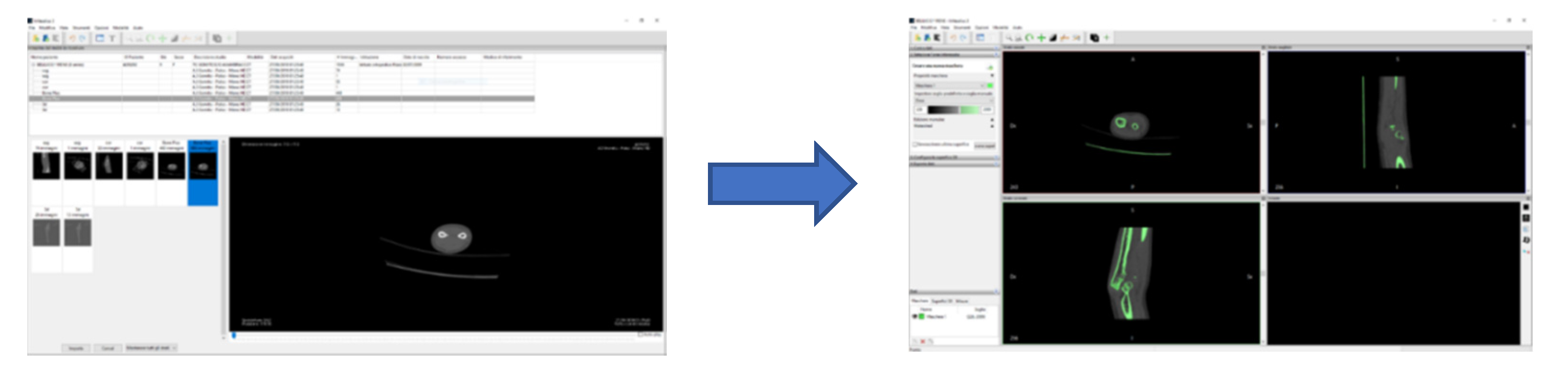
| OPEN SOURCE | INVESALIUS | Invesalius is a medical 3D visualization software that, starting from images in DICOM format acquired by computer tomography or magnetic resonance imaging, generates 3D models of the anatomical parts examined. |  |
| MESHLAB | Meshlab is a software for editing and managing 3D meshes, allowing you to process three-dimensional surfaces through multiple cleaning, correction and conversion tools. It provides the ability to automatically remove duplicate vertices mesh, isolated or overlapping surfaces and unconnected edges without references, generating an output model that is not only clean, but also significantly lighter and therefore easier to work. |  | |
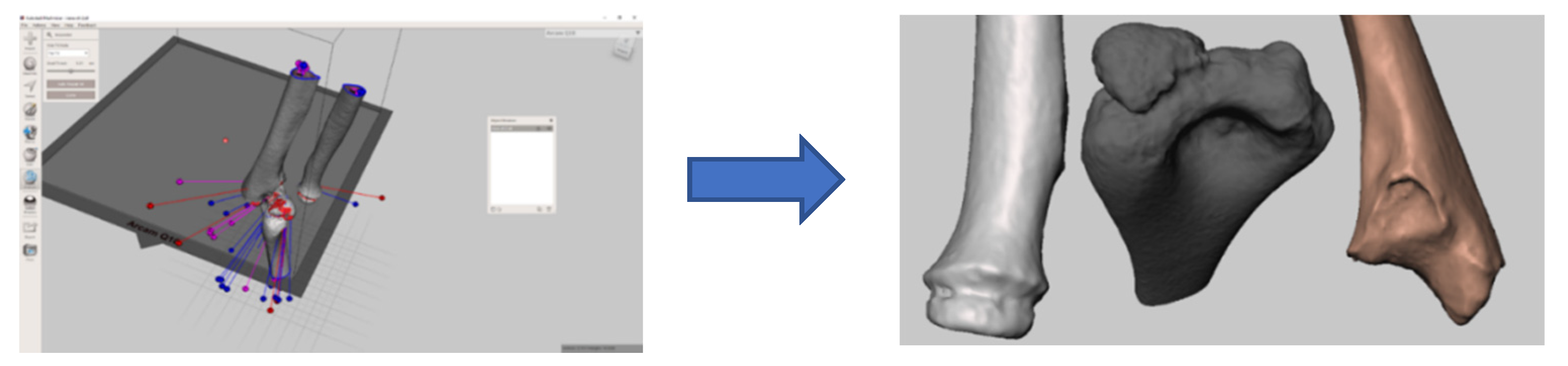
| MESHMIXER | Meshmixer by Autodesk is a complementary program and, for certain features, is very similar to Meshlab. It is always focused on the modification and management of the three-dimensional mesh but is specialized mainly on surface modeling. Perhaps the most interesting feature supported is the various brushes; tools with an adjustable range for both the area of action and the intensity of change, with which the defects of the surface analyzed are resolved in a targeted way. |  | |
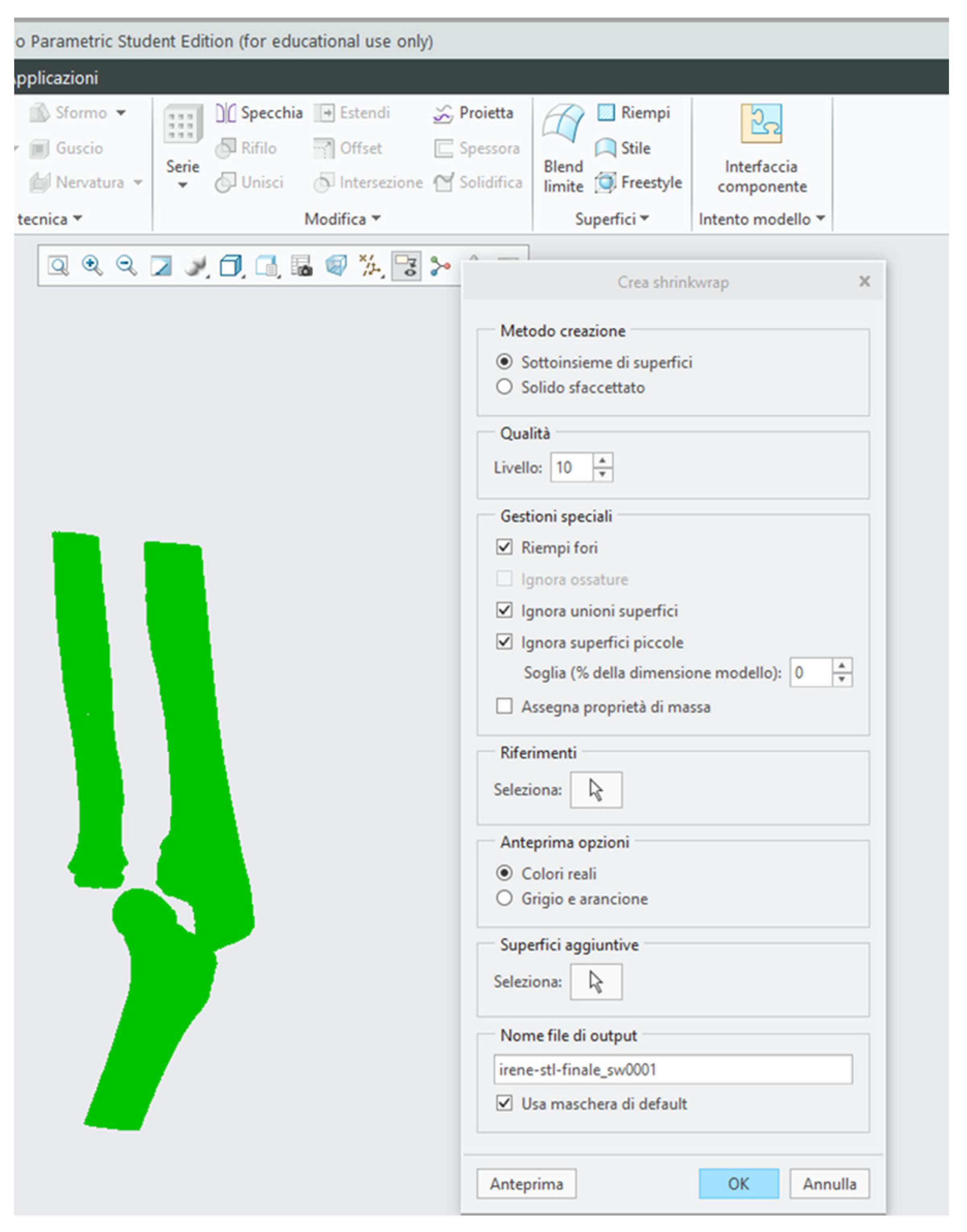
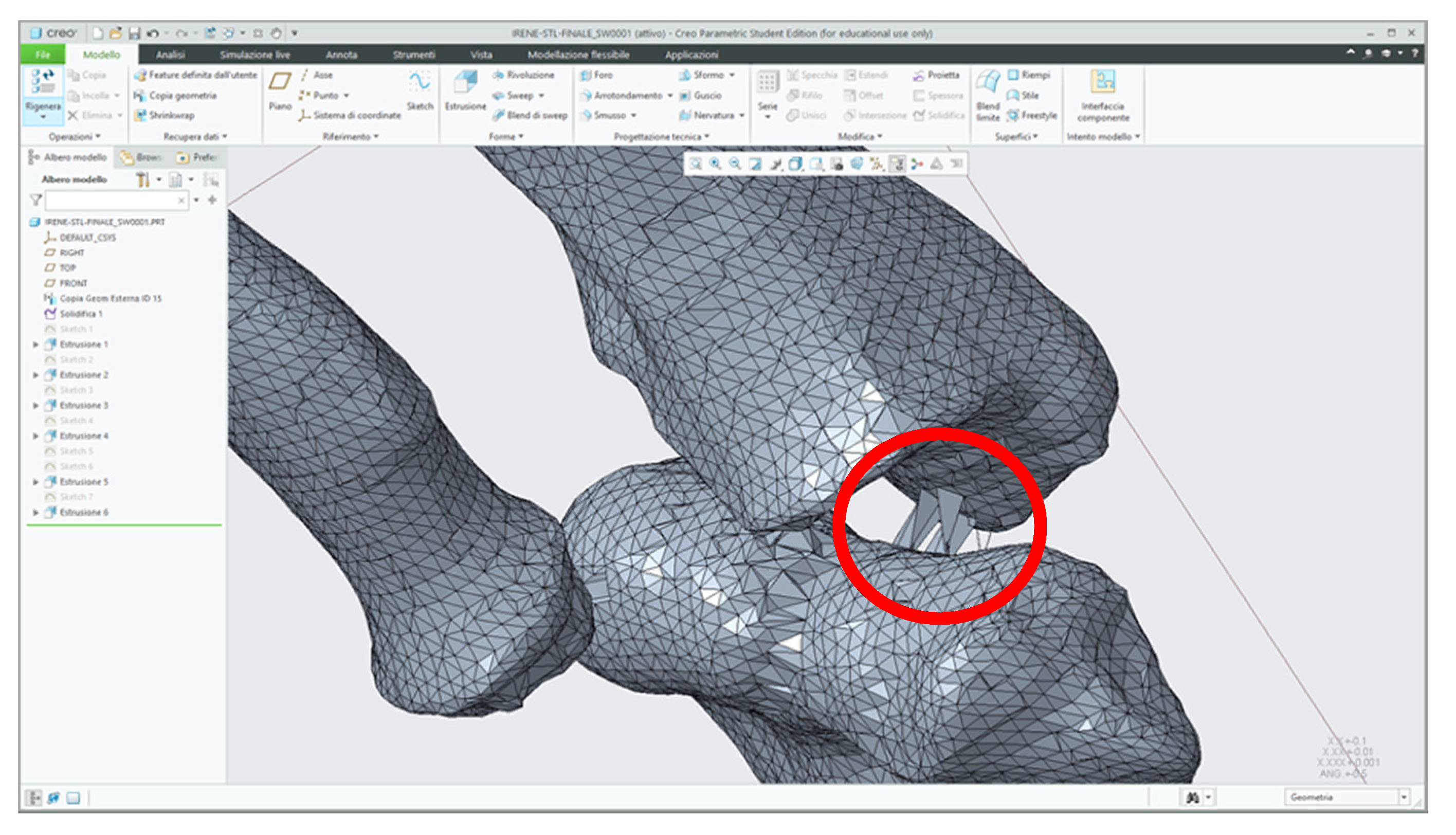
| PARAMETRIC | CREO | Creo Parametric is part of a family of CAD software products for mechanical design, developed by PTC, and is the fundamental application dedicated to parametric modeling. The software supports different work environments, each of which is proper to a specific type of modeling. You can work single solid objects, draw flat geometries, form and fold sheet metal or generate complex assemblies. |  |
| Pathology | Description of the Case | Initial Examination |
|---|---|---|
| Osteochondrosis of the elbow | The patient had a post-traumatic deformity of the left elbow with important functional limitation and stiffness. Preoperative CT showed a picture of severe osteochondrosis with extensive anterior and posterior ossifications and sub-ankylosis. |  |
| Post-traumatic deformity of the forearm | Forearm articulation of a pediatric patient suffering from post-traumatic deformity. The picture saw the involvement of both the bones of the forearm, with a greater deformity of the radius. Deformities resulting from an abnormal consolidation of a past two-bone fracture resulted in severe limitations in particular to the movement of supination. Deformity occurred on all three planes of space, defining itself as a highly complex picture [25]. |  |
| Monteggia lesion | Very complex pathology which occurs as a result of trauma and falls and which leads to a dislocation of the radial capital. The most likely hypothesis of the injury mechanism is the fall on the extended elbow hand in neutral rotation or slight pronation of the forearm. The ulna is stressed in the anterior direction, initially suffering a plastic deformation that can remain as such or evolve towards the fracture of the ulna, causing precisely the dislocation of the radial capital [26]. |  |
| Cubitus varus | Elbow deformation caused by a deflection of the forearm inwards. In the patient the axis of the humerus forms with the axis of the ulna–radius complex an angle in the medial position of a width not exceeding 5°, while in healthy persons the aforesaid angle measures between 11° and 14° [27]. |  |
| Blount disease | Growth disorder due to a suffering of the inner slope of the proximal accretion cartilage of the tibia that causes a progressive appearance of the knee varus. The latter consists of an angle at the outer vertex of the femur–tibial axis which, if bilateral, achieves the typical deformity at “O” or “brackets” [28]. |  |
| Spondyloepiphyseal dysplasia and bilateral coxa vara | Varus abnormality at the femoral neck. This is the angle between the neck femur shaft being less than 110–120° (normally between 135°–145°) in children [29]. |  |
| Ollier syndrome | Rare condition categorized by abnormal bone growth (skeletal dysplasia). Although this disorder may be present at birth (congenital), it is not noticed until early childhood as symptoms like deformities or unsuitable limb growth become obvious. This disease primarily affects the long bones and joint cartilages in the extremities, at the area where the shaft and head of a long bone meet [30]. |  |
| Software | Specific Requirements for Input and Processing the Data |
|---|---|
| InVesalius | The selection of the density range for the anatomical portion that you want to export takes place through the use of masks. A default range is available (for instance, compact bone, spongy bone, muscular tissue, skin, etc.) or it can be changed manually; because using the software masks was never accurate enough to highlight the 3D printable volume, it was needed to adjust this first automatic selection with manual corrections. |
| MeshLab | The main filter is the ambient occlusion which is a shading technique used to compute how exposed each mesh in a scene is to ambient enlightenment; this simulates a diffused global illumination that darkens enclosed areas, allowing us to select and delete the internal points with a simple range instruction. |
| MeshMixer | The modification intensity is adjusted by the “strength” of the brushes for surface modification. They are manual tools that require precision and criteria as well as time, as it is recommended to work with a narrow range of action. |
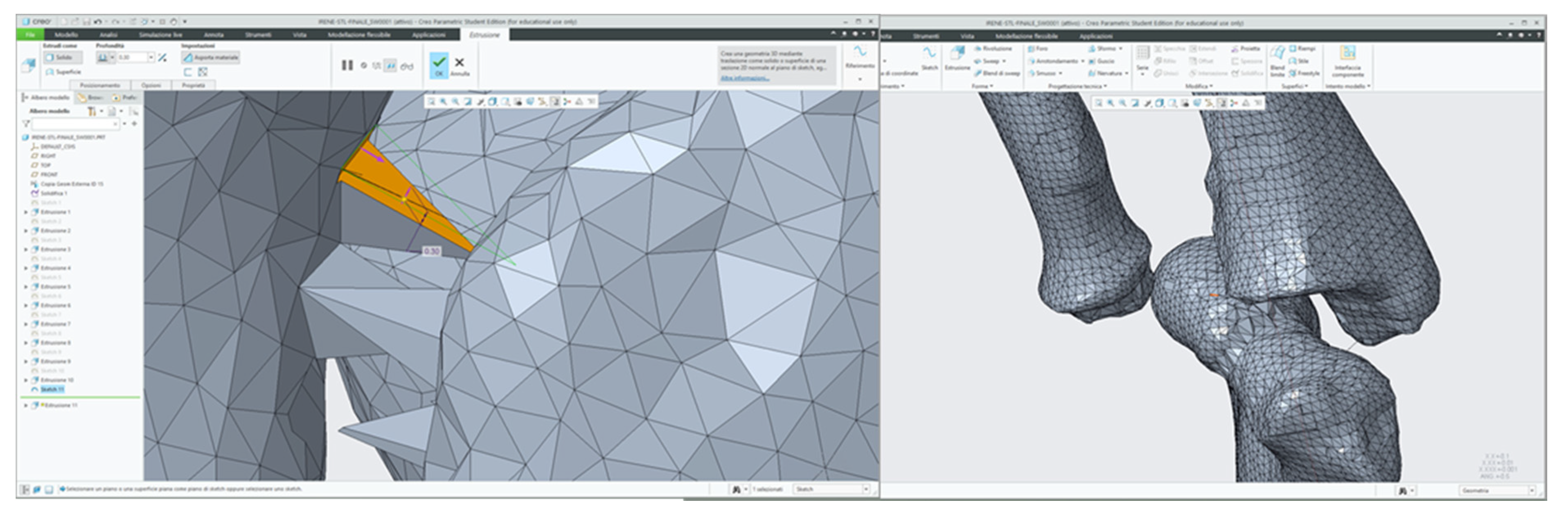
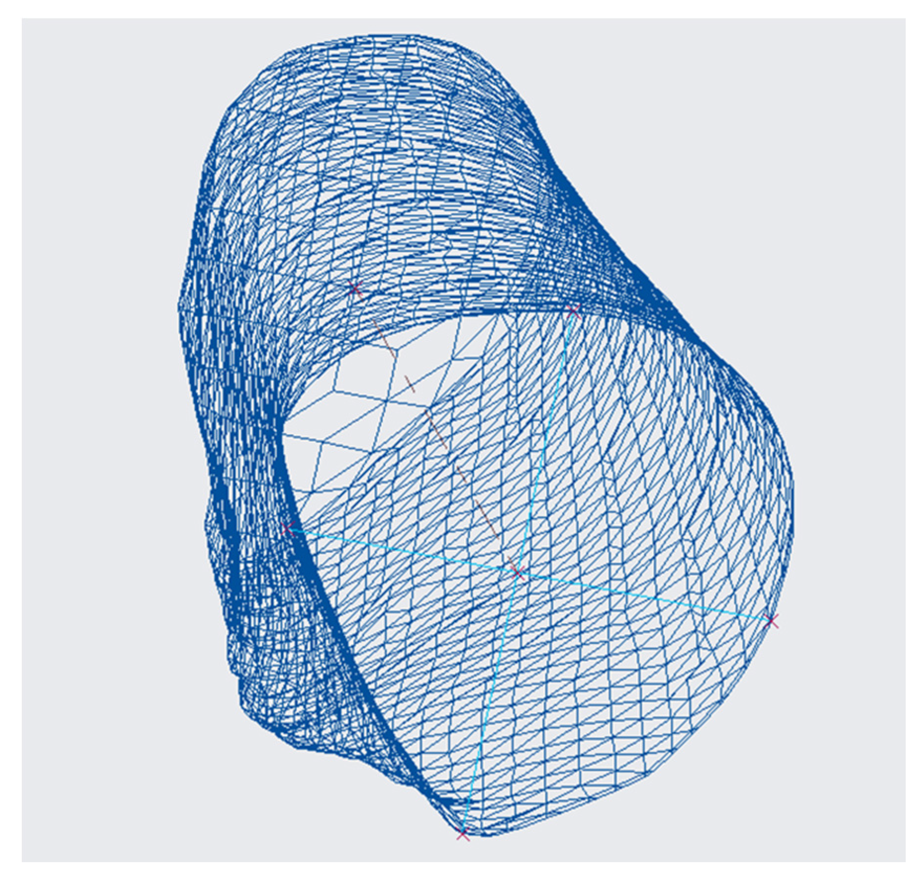
| CREO | With the Shrinkwrap command you set the quality degree with which you intend to import the stl file. With level 10 almost all the meshes are maintained and a three-dimensional solid is obtained that perfectly represents the geometry of the anatomical part taken into consideration. |
| Pathology | Output File from CREO | Actual Surgery |
|---|---|---|
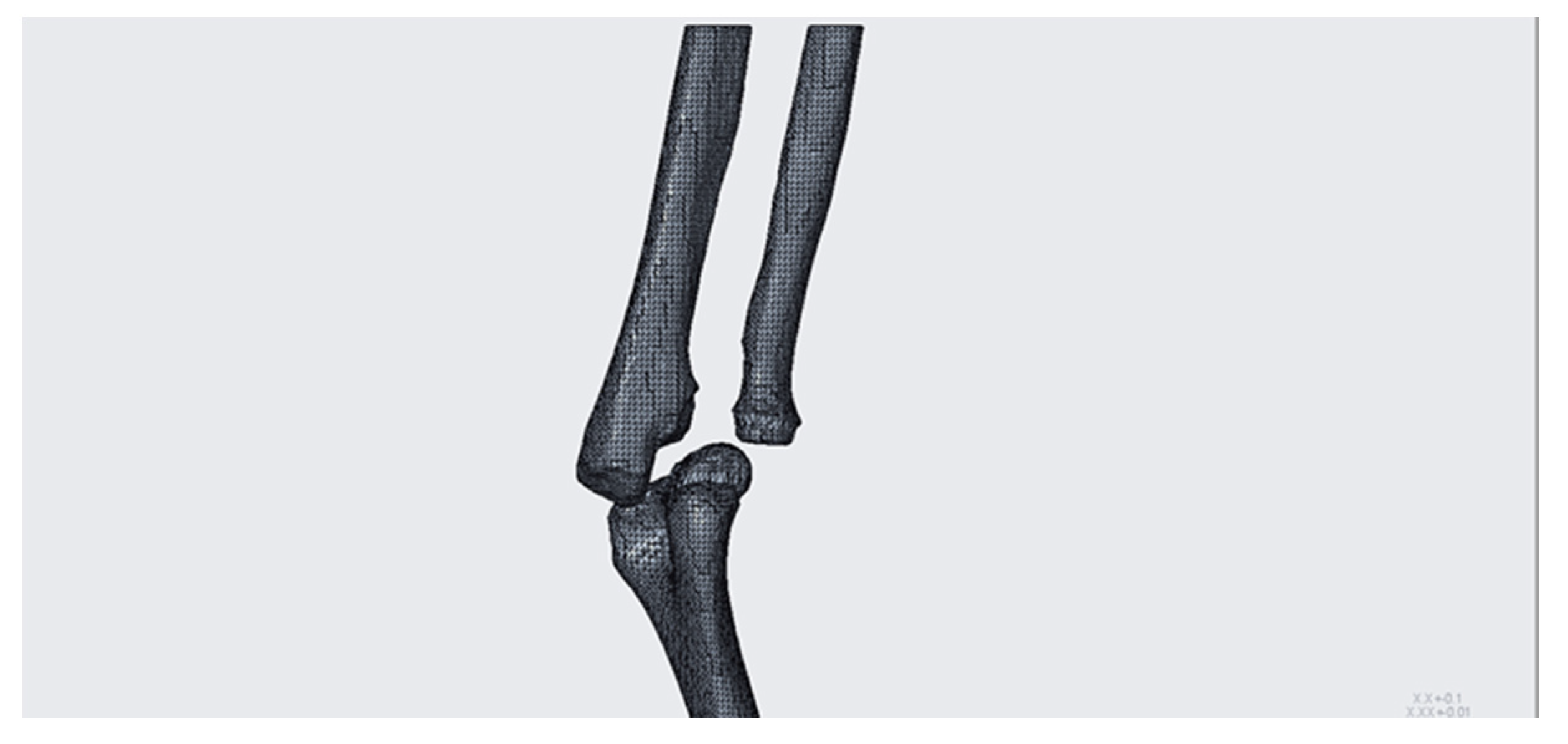
| Osteochondrosis of the elbow. Viewing the bones individually, it has been possible to ascertain the complexity of the case, in particular with regard to the components distal humerus and proximal ulna. |  | |
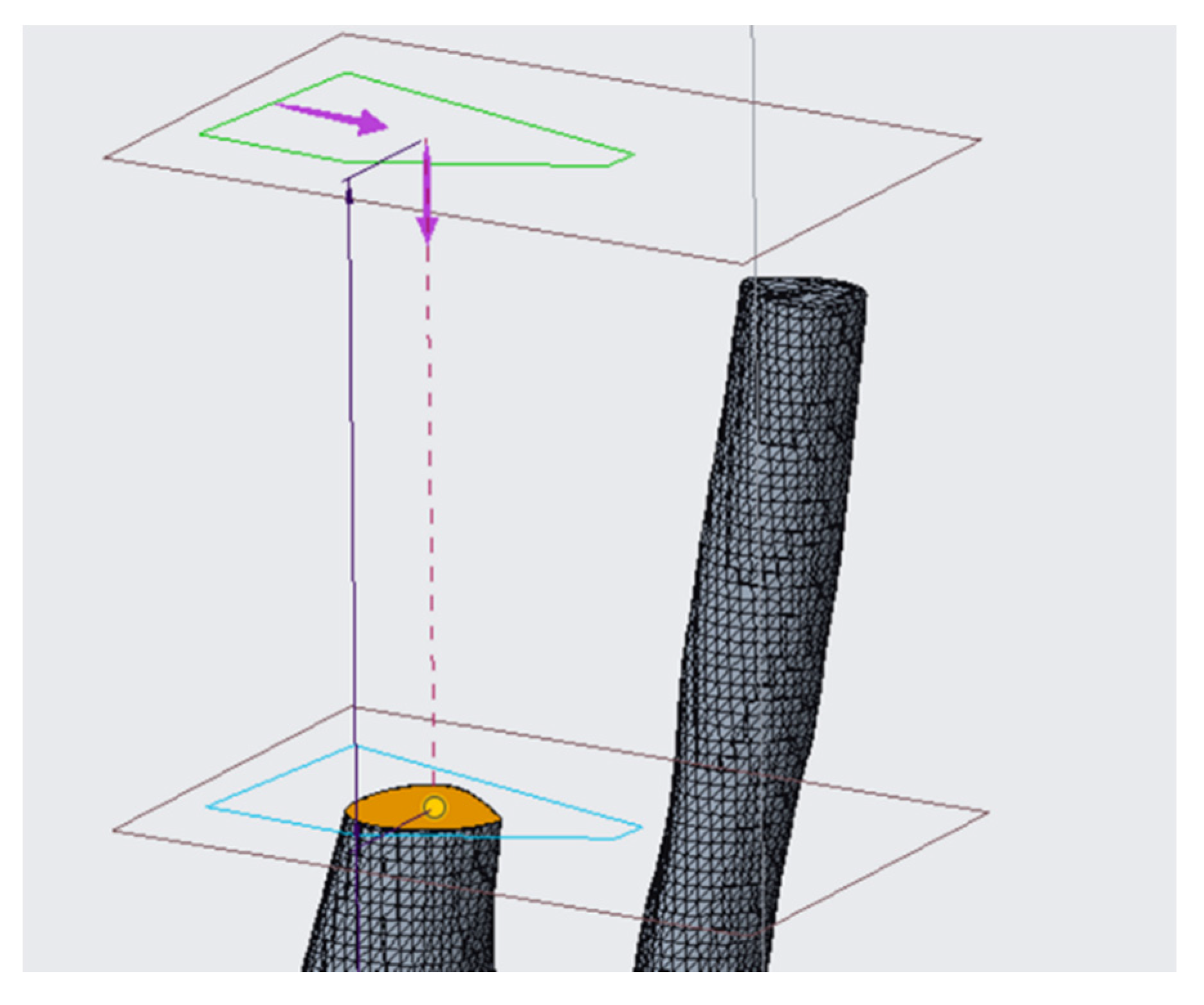
| Post-traumatic deformity of the forearm. The planned corrective intervention is defined by a radial osteotomy with a wedge in subtraction associated with the ulnar osteotomy. Cutting plans for osteotomy have been located, in particular: the upper horizontal plane and the inclined plane identify the bone wedge on the radius intended to be removed in order to correct the axial angular deformation. |  |  |
| Monteggia lesion. To allow the displacement of the radial capital and the reduction of the dislocation, an intervention with a wedge to place in the diaphysis of the ulna, on the elbow side, is adopted. The dimensions of the bone that is inserted must be very precise to allow a correct repositioning of the radius, in particular in relation to the inter-bone membrane, an anatomical component with a certain elastic resistance that, if not held in account, could affect the success of the operation. |  |  |
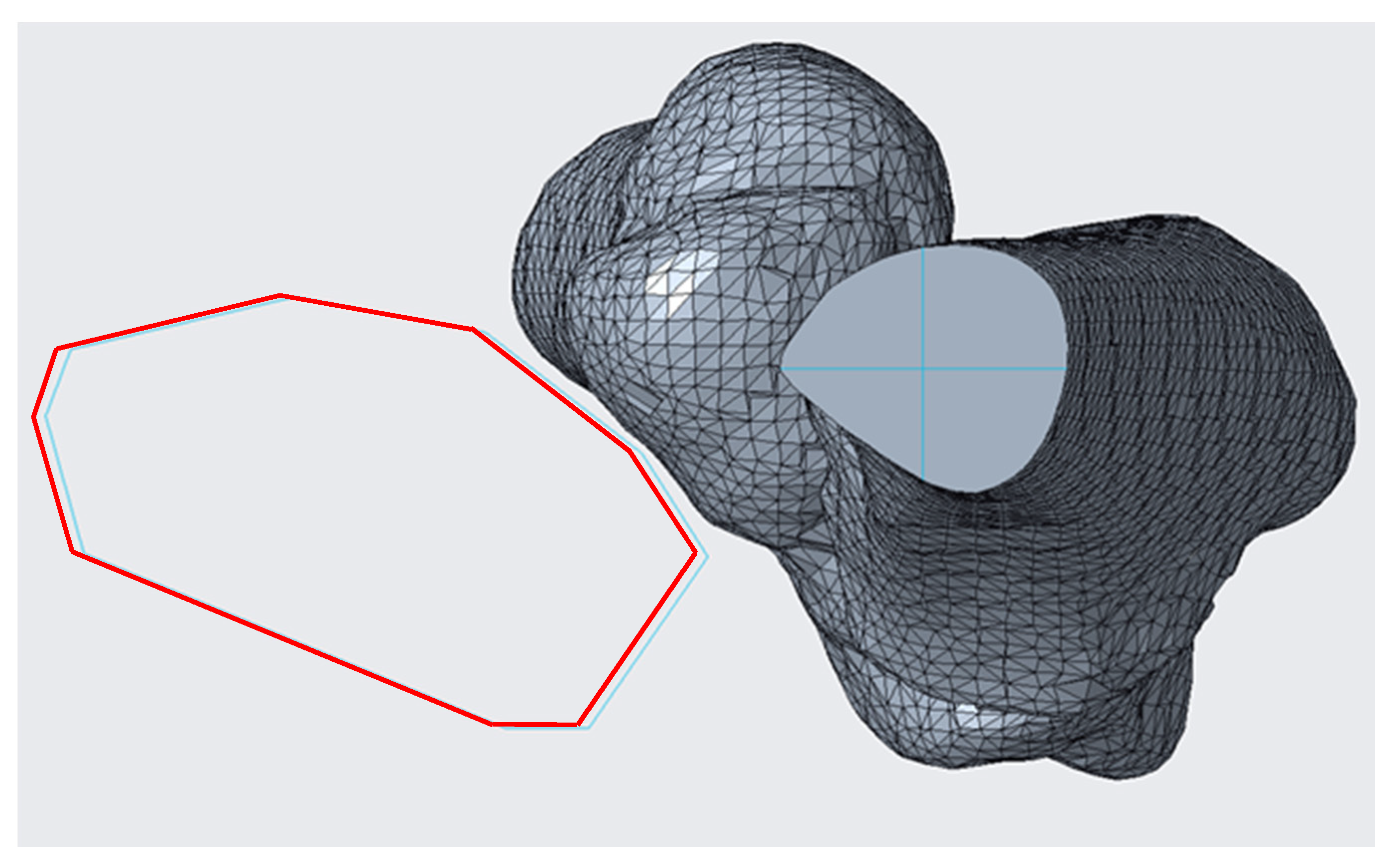
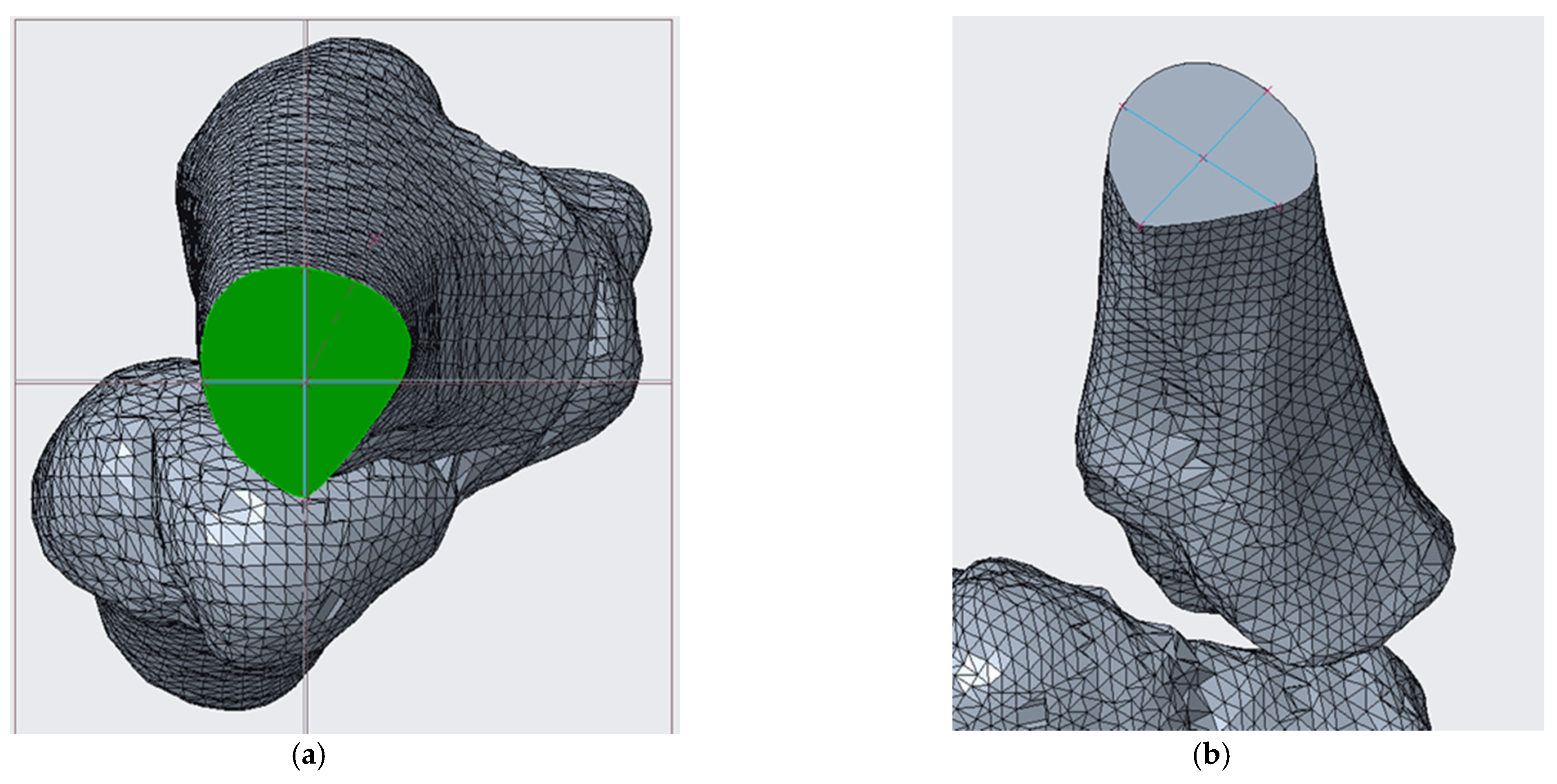
| Cubitus varus. The plane of the distal osteotomy, approximately parallel to the distal articular surface, is placed at a distance of about 10 mm above the olecranon fossa. The proximal osteotomy plane forms with the distal one an angle of width equal to 22°. To proceed with the simulation and, therefore, with the removal of the wedge of bone, it is necessary to divide the humerus into three parts. It is necessary that the cut occurs near the floors found [11]. |  | |
| Blount disease. Osteotomy to lift the tibial plateau. In the present case, the addition osteotomy is not sufficient because the varus is so severe that the therapy requires further osteotomy. This last one consists of a semicircular cut “to dome” under the tibial tuberosity, with the aim of correcting the anatomical axis and internal rotation. The angle of femoral–tibial rotation is given by the surgeon and is equal to 24° [20]. |  |  |
| Spondyloepiphyseal dysplasia and bilateral coxa vara. With the 3D model measurements of the patient on Creo Parametric, it could be corrected the first estimates made and obtained a varus deformity of about 78°; the angle of opening of the wedge with which the osteotomy should be performed is (78° − 16°) = 62°. |  | |
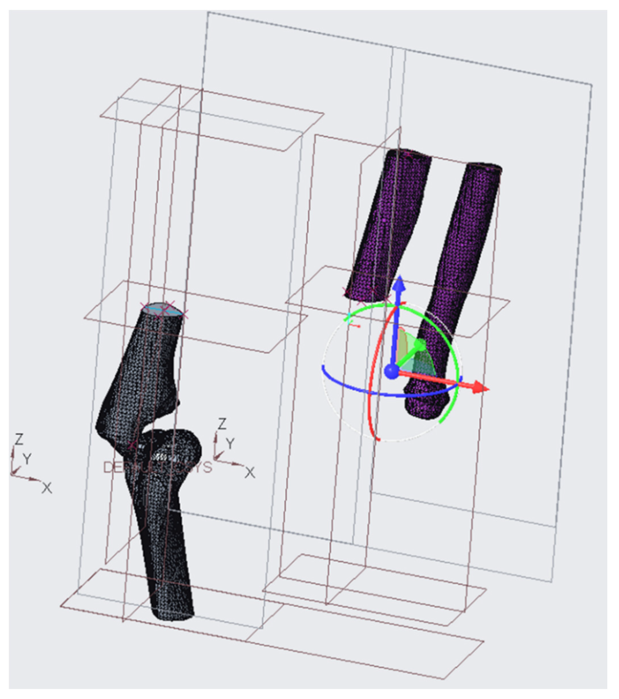
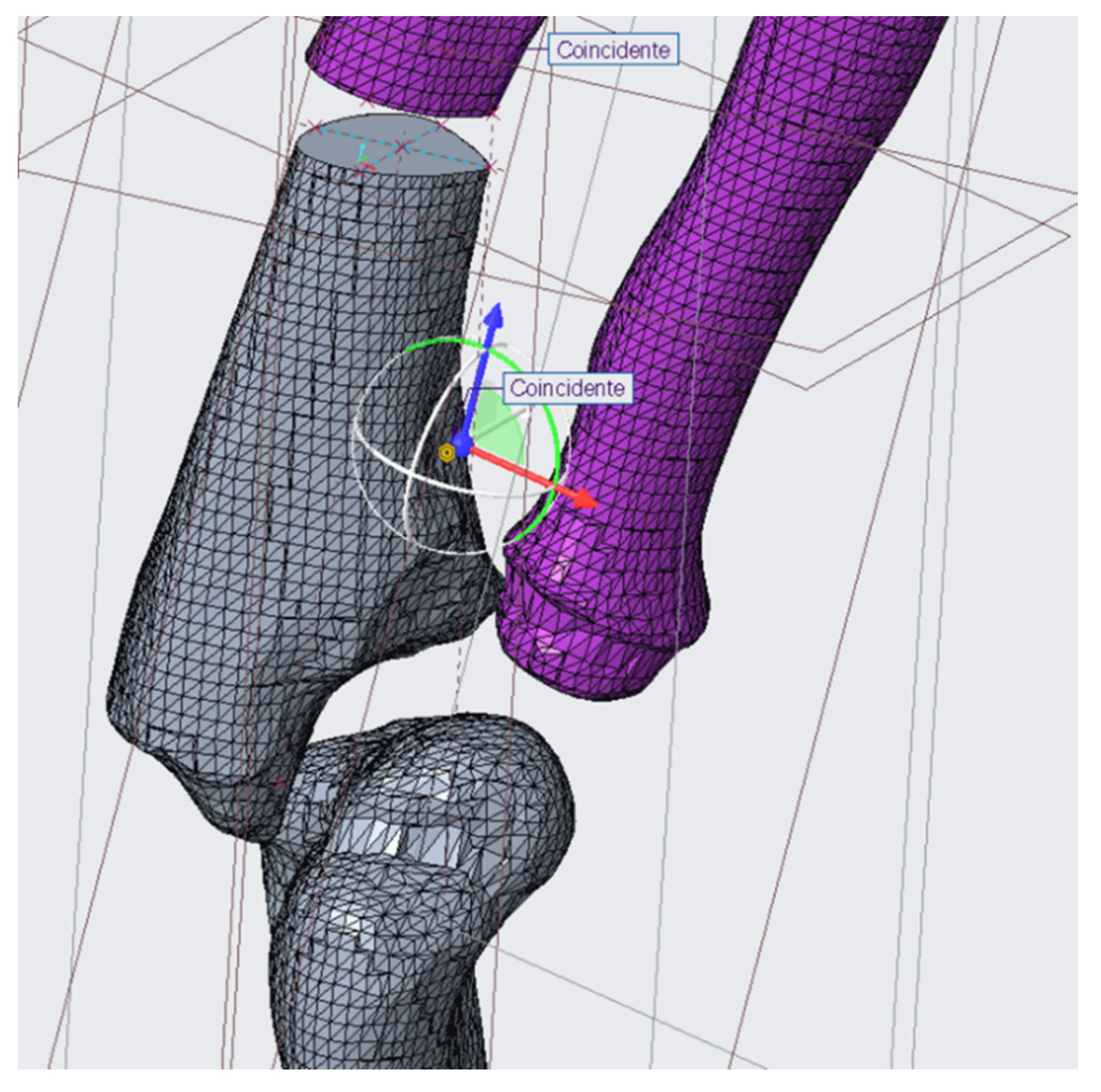
| Ollier syndrome. It was necessary to completely correct the inclination of the distal epiphysis. To solve the pathology there has been inserted an electromagnetic pin; in addition to ensuring relative positions between the two bone segments obtained with osteotomy, this will undergo a progressive electro-stimulated elongation to allow the patient to regain the normal length of the femur. It was also possible to size the fasteners for the operation [31]. |  | |
Publisher’s Note: MDPI stays neutral with regard to jurisdictional claims in published maps and institutional affiliations. |
© 2021 by the authors. Licensee MDPI, Basel, Switzerland. This article is an open access article distributed under the terms and conditions of the Creative Commons Attribution (CC BY) license (https://creativecommons.org/licenses/by/4.0/).
Share and Cite
Frizziero, L.; Pagliari, C.; Donnici, G.; Liverani, A.; Santi, G.M.; Papaleo, P.; Napolitano, F.; Leon-Cardenas, C.; Trisolino, G.; Zarantonello, P.; et al. Effectiveness Assessment of CAD Simulation in Complex Orthopedic Surgery Practices. Symmetry 2021, 13, 850. https://doi.org/10.3390/sym13050850
Frizziero L, Pagliari C, Donnici G, Liverani A, Santi GM, Papaleo P, Napolitano F, Leon-Cardenas C, Trisolino G, Zarantonello P, et al. Effectiveness Assessment of CAD Simulation in Complex Orthopedic Surgery Practices. Symmetry. 2021; 13(5):850. https://doi.org/10.3390/sym13050850
Chicago/Turabian StyleFrizziero, Leonardo, Curzio Pagliari, Giampiero Donnici, Alfredo Liverani, Gian Maria Santi, Paola Papaleo, Francesca Napolitano, Christian Leon-Cardenas, Giovanni Trisolino, Paola Zarantonello, and et al. 2021. "Effectiveness Assessment of CAD Simulation in Complex Orthopedic Surgery Practices" Symmetry 13, no. 5: 850. https://doi.org/10.3390/sym13050850