
Assessment of Contact Pressures between a Mandibular Overdenture and the Prosthodontic Area

 , , ,
, , ,
Abstract
:1. Introduction
2. Materials and Method
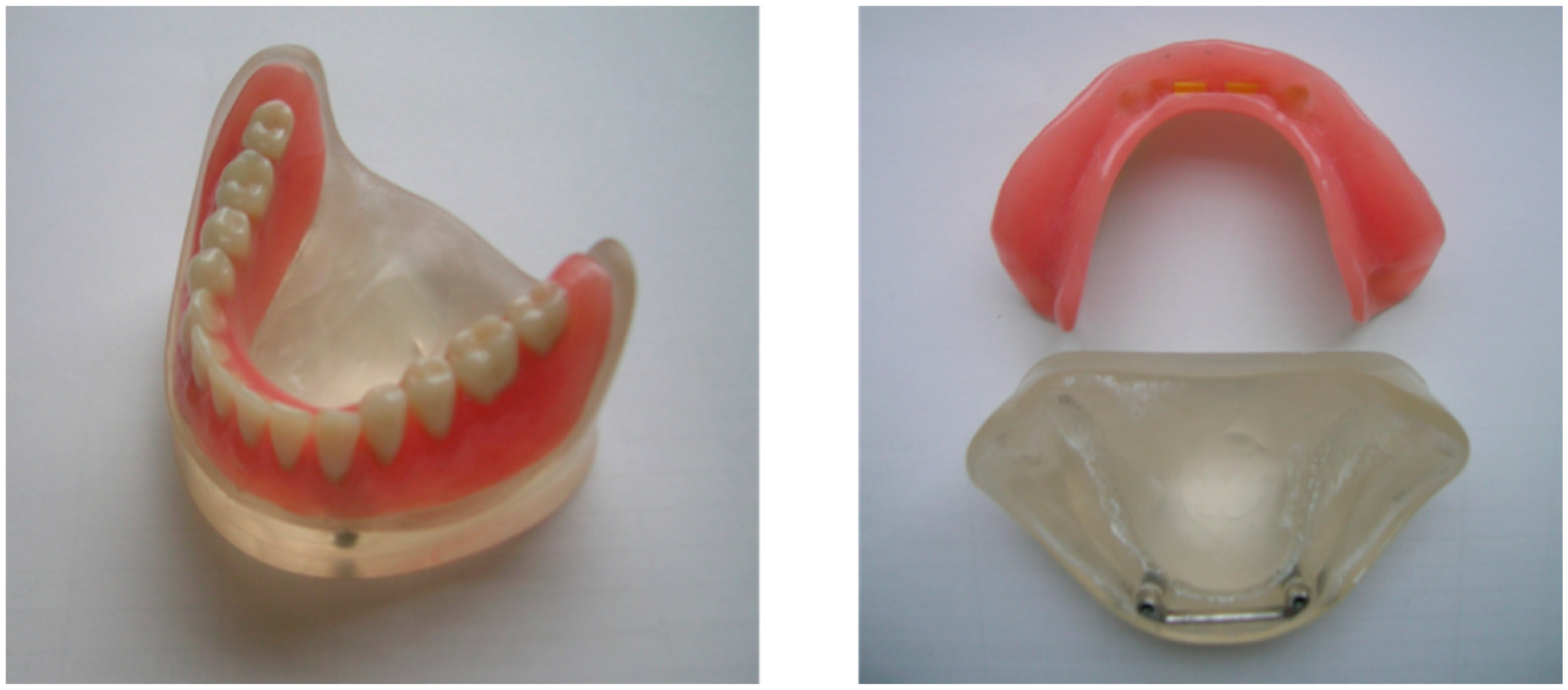
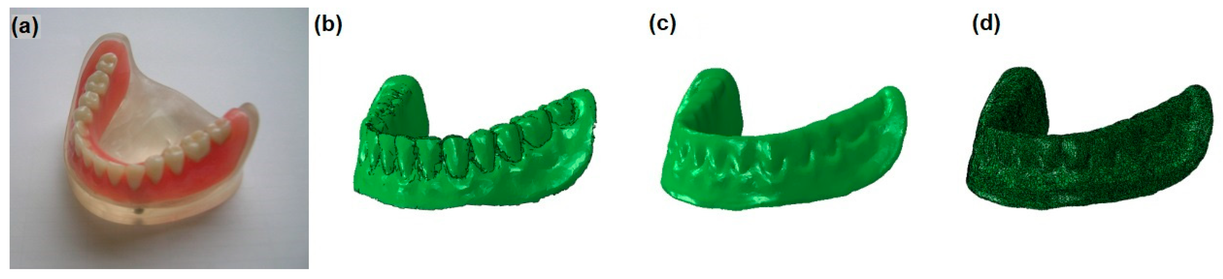
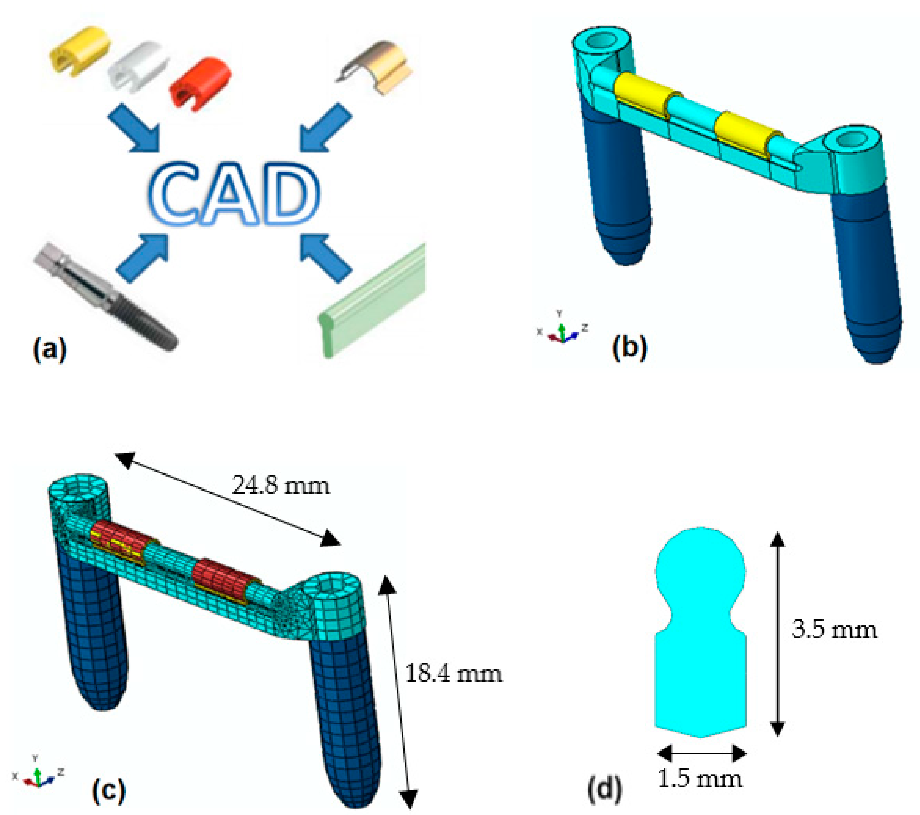
2.1. Geometry Acquisition
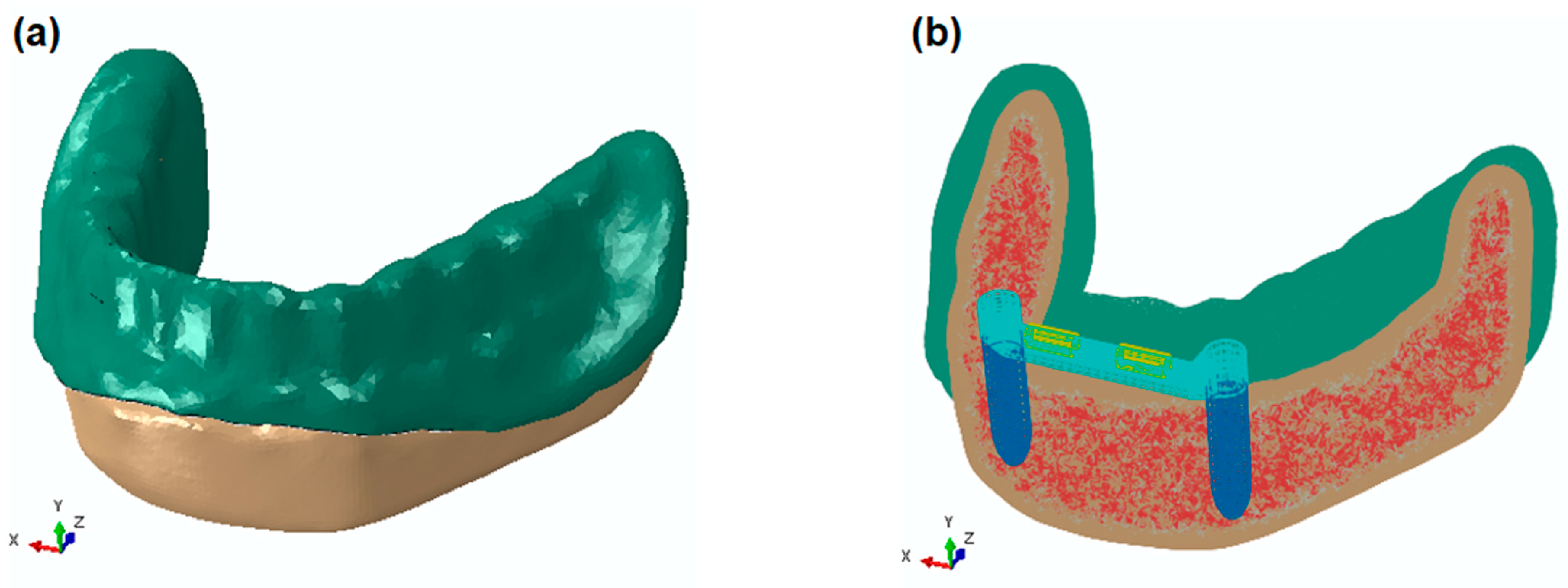
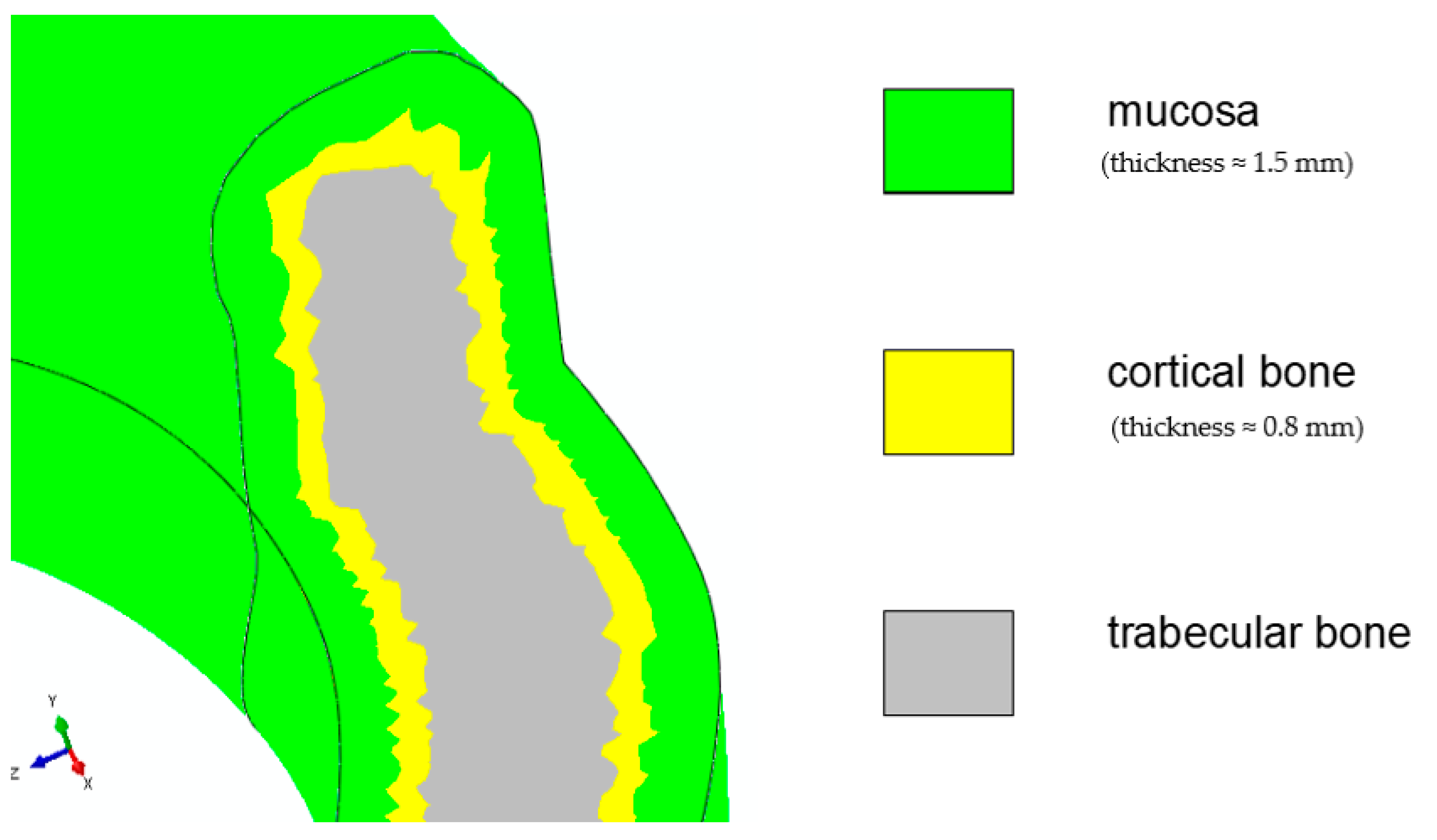
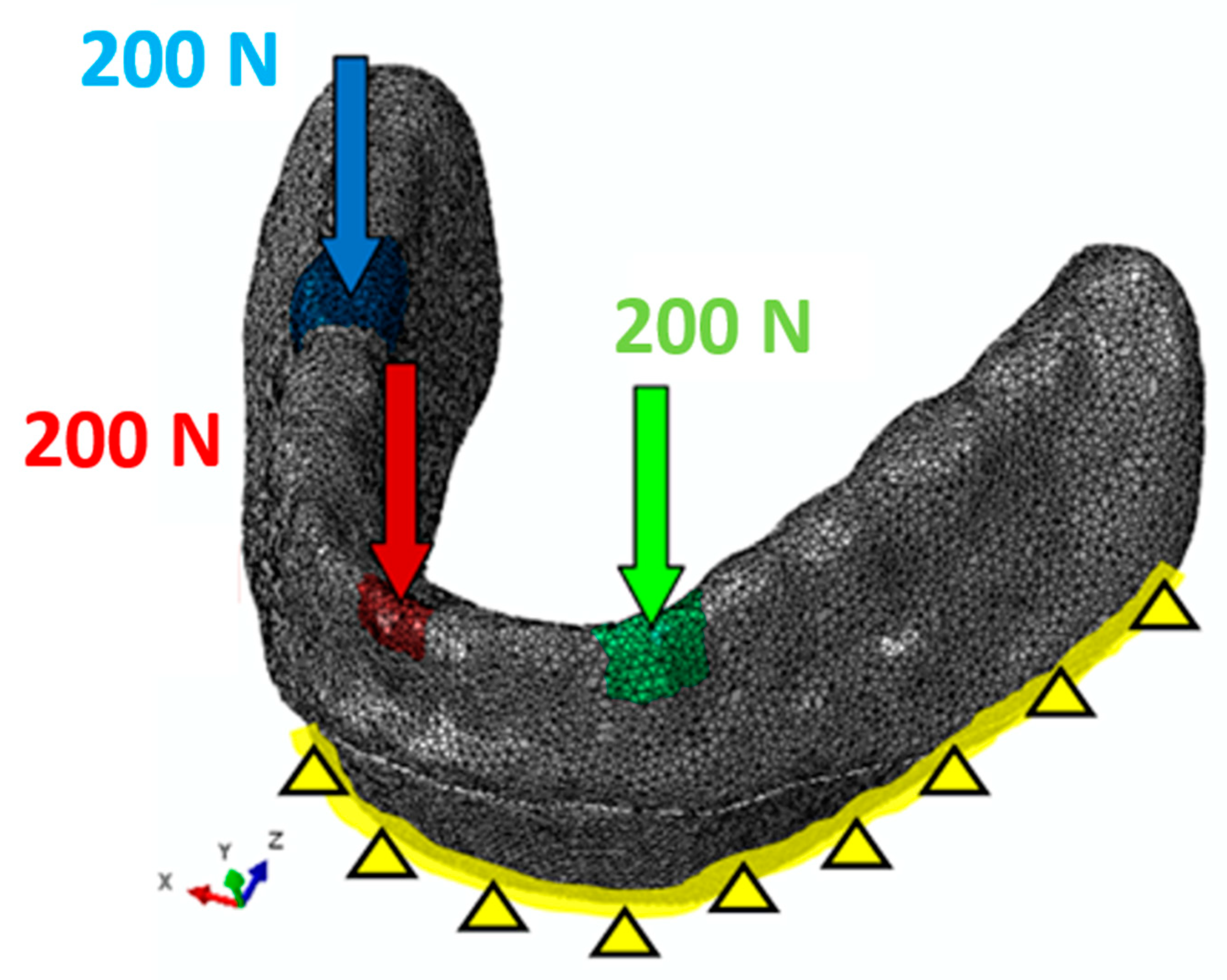
2.2. Finite Element Method Model
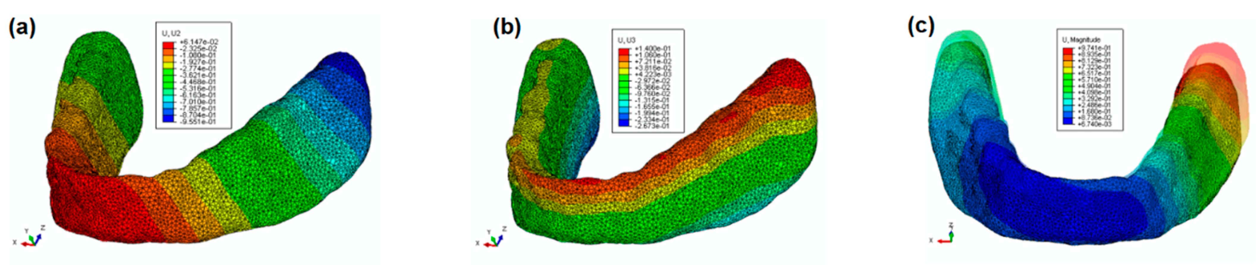
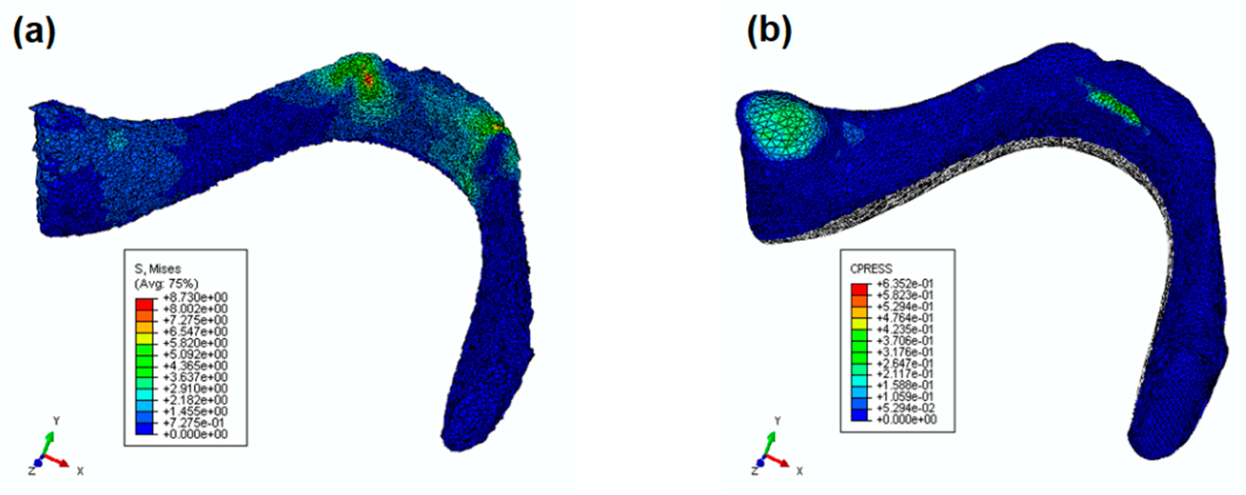
3. Results and Discussion
4. Conclusions
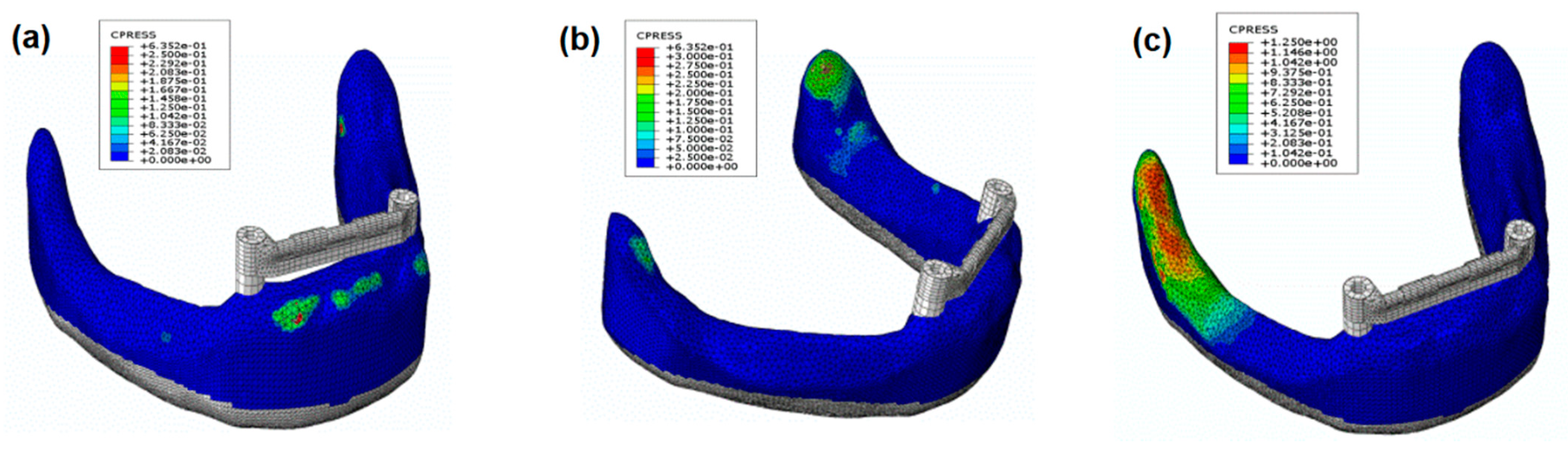
- In the anterior zone, the applied load produces a slight contact pressure between the denture and the prosthodontic area.
- In the lateral zone, the applied load produces the largest contact pressure between the denture and the prosthodontic area on the working side around the retromolar pad.
- This study proved that the most unfavorable forces are those applied to a canine.
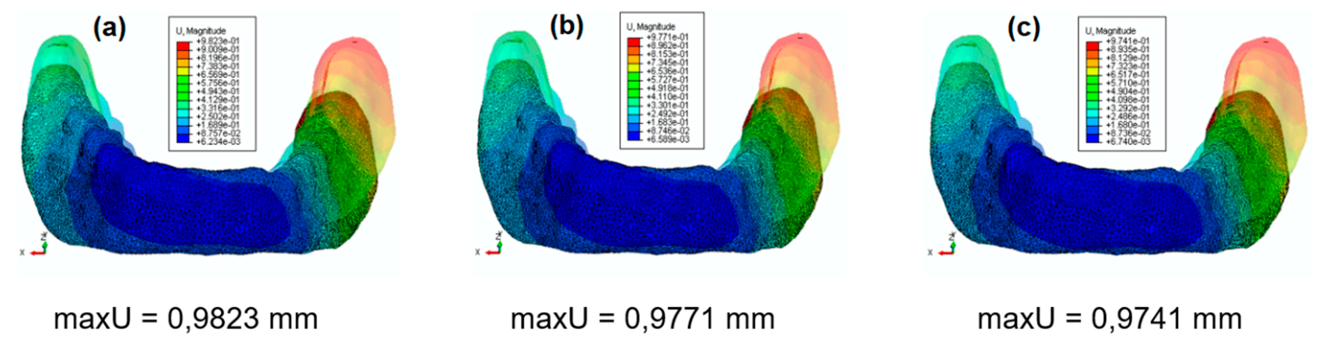
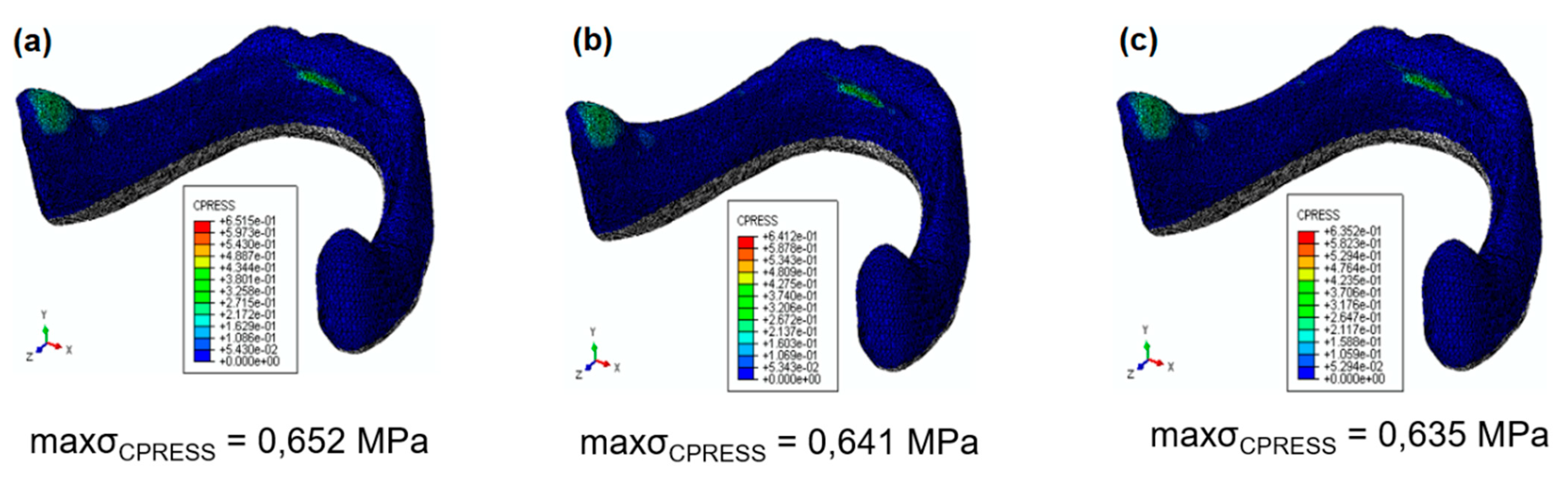
- A change in polypropylene matrix stiffness does not affect the obtained contact pressure field.
Author Contributions
Funding
Institutional Review Board Statement
Informed Consent Statement
Data Availability Statement
Conflicts of Interest
References
- Schierano, G.; Manzella, C.; Menicucci, G.; Parrotta, A.; Zanetti, E.M.; Audenino, A.L. In vitro standardization of two different removal devices in cemented implant prosthesis. Clin. Oral Implants Res. 2015, 27, 1492–1499. [Google Scholar] [CrossRef] [PubMed]
- Lugas, A.T.; Terzini, M.; Zanetti, E.M.; Schierano, G.; Manzella, C.; Baldi, D.; Bignardi, C.; Audenino, A.L. In vitro impact testing to simulate implant-supported prosthesis retrievability in clinical practice: Influence of cement and abutment geometry. Materials 2020, 13, 1749. [Google Scholar] [CrossRef] [Green Version]
- El-Anwar, M.I.; El-Taftazany, E.A.; Hamed, H.A.; ElHay, M.A.A. Influence of number of implants and attachment type on stress distribution in mandibular implant-retained overdentures: Finite element analysis. Open Access Maced. J. Med. Sci. 2017, 5, 244–249. [Google Scholar] [CrossRef] [PubMed]
- Matthys, C.; Vervaeke, S.; Besseler, J.; Doornewaard, R.; Dierens, M.; De Bruyn, H. Five years follow-up of mandibular 2-implant overdentures on locator or ball abutments: Implant results, patient-related outcome, and prosthetic aftercare. Clin. Implant Dent. Relat. Res. 2019, 21, 835–844. [Google Scholar] [CrossRef]
- Khurana, N.; Rodrigues, S.; Shenoy, S.; Saldanha, S.; Pai, U.; Shetty, T.; Mahesh, M.; Hegde, P. A comparative evaluation of stress distribution with two attachment systems of varying heights in a mandibular implant-supported overdenture: A three-dimensional finite element analysis. J. Prosthodont. 2019, 28, 795–805. [Google Scholar] [CrossRef] [PubMed]
- Keshk, A.M.; Alqutaibi, A.Y.; Algabri, R.S.; Swedan, M.S.; Kaddah, A. Prosthodontic maintenance and peri-implant tissue conditions for telescopic attachment-retained mandibular implant overdenture: Systematic review and meta-analysis of randomized clinical trials. Eur. J. Dent. 2017, 11, 559–568. [Google Scholar] [CrossRef]
- Preti, G.; Martinasso, G.; Peirone, B.; Navone, R.; Manzella, C.; Muzio, G.; Russo, C.; Canuto, R.A.; Schierano, G. Cytokines and growth factors involvedin the osseointegration of oral titanium implants positioned using piezoelectric bone surgery versus a drill technique: A pilot study in Minipigs. J. Periodontol. 2007, 78, 716–722. [Google Scholar] [CrossRef] [Green Version]
- Redžepagi´c-Vražalica, L.; Mešić, E.; Pervan, N.; Hadžiabdić, V.; Delić, M.; Glušac, M. Impact of implant design and bone properties on the primary stability of orthodontic mini-implants. Appl. Sci. 2021, 11, 1183. [Google Scholar] [CrossRef]
- Chen, J.; Suenaga, H.; Hogg, M.; Li, W.; Swain, M.; Li, Q. Determination of oral mucosal Poisson’s ratio and coefficient of friction from in-vivo contact pressure measurements. Comput. Methods Biomech. Biomed. Eng. 2016, 19, 357–365. [Google Scholar] [CrossRef]
- Misch, C.E. Contemporary Implant Dentistry; International Congress of Oral Implantologists: St. Louis, MO, USA; Mosby, Norway, 1999. [Google Scholar]
- Łodygowski, T.; Wierszycki, M.; Szajek, K.; Hȩdzelek, W.; Zagalak, R. Tooth-implant life cycle design. In Computer Methods in Mechanics; Kuczma, M., Wilmanski, K., Eds.; Advanced structured materials; Springer: Berlin/Heidelberg, Germany, 2010; Volume 1. [Google Scholar]
- Assuncao, W.G.; Tabata, L.F.; Barao, V.A.R.; Rocha, E.P. Comparison of stress distribution between complete denture and implant-retained overdenture-2D FEA. J. Oral Rehabil. 2008, 35, 766–774. [Google Scholar] [CrossRef]
- Holmes, P.B.; Wolf, B.J.; Zhou, J. A CBCT atlas of buccal cortical bone thickness in interradicular spaces. Angle Orthod. 2015, 85, 911–919. [Google Scholar] [CrossRef] [PubMed] [Green Version]
- Abaqus Analysis User’s Guide, p. 29.6 Shell Elements; Dassault Systèmes Simulia Corp: Providence, RI, USA, 2015.
- Abaqus Analysis User’s Guide, p. 28.1 General-Purpose Continuum Elements; Dassault Systèmes Simulia Corp: Providence, RI, USA, 2015.
- Getting Started with Abaqus: Interactive Edition, p. 4.1 Element formulation and integration; Dassault Systèmes Simulia Corp: Providence, RI, USA, 2014.
- Abaqus Theory Guide, p. 3.2.4 Solid Isoparametric Quadrilaterals and Hexahedra; Dassault Systèmes Simulia Corp: Providence, RI, USA, 2016.
- Abaqus Theory Guide, p. 3.6.5 Finite-Strain Shell Element Formulation; Dassault Systèmes Simulia Corp: Providence, RI, USA, 2016.
- Fernandez, M.A.; Subramanian, N.; Nawrocki, M.; Nawrocki, A.; Craighead, J.; Clark, A.; O’Neill, E.; Esquivel-Upshaw, J. Finite element analysis (FEA) of palatal coverage on implant retained maxillary overdentures. Appl. Sci. 2020, 10, 6635. [Google Scholar] [CrossRef]
- Abaqus Analysis User’s Guide, p. 35.4 Embedded Elements; Dassault Systèmes Simulia Corp: Providence, RI, USA, 2015.
- Abaqus Analysis User’s Guide, p. 37.1.2 Contact Pressure-Overclosure Relationships; Dassault Systèmes Simulia Corp: Providence, RI, USA, 2015.
- Abaqus Analysis User’s Guide, p. 37.1.5 Frictional Behavior; Dassault Systèmes Simulia Corp: Providence, RI, USA, 2015.
- Bonnet, A.S.; Postaire, M.; Lipinski, P. Biomechanical study of mandible bone supporting a four-implant retained bridge: Finite element analysis of the influence of bone anisotropy and foodstuff position. Med. Eng. Phys. 2009, 32, 806–815. [Google Scholar] [CrossRef] [PubMed]
- Pilarska, A.; Bula, K.; Myszka, K.; Rozmanowski, T.; Szwarc-Rzepka, K.; Pilarski, K.; Chrzanowski, Ł.; Czaczyk, K.; Jesionowski, T. Functional polypropylene composites filled with ultra-fine magnesium hydroxide. Open Chem. 2015, 13, 161–171. [Google Scholar] [CrossRef]
- Pilarska, A.; Paukszta, D.; Bula, K.; Mazur, M.; Jesionowski, T. Physico-chemical and usable properties of magnesium hydroxide obtained by conversion of various precursors with ammonium hydroxide. Chem. Ind. 2012, 91, 1400–1406. [Google Scholar]
- Australian Stainless Steel Development Associatic Technical Info; Dassault Systèmes Simulia Corp: Providence, RI, USA, 2020.
- Chen, J.; Ahmad, R.; Li, W.; Swain, M.; Li, Q. Biomechanics of oral mucosa. J. R. Soc. Interface 2015, 12, 20150325. [Google Scholar] [CrossRef] [Green Version]
- Meniccuci, G.; Lorenzetti, M.; Pera, P.; Preti, G. Mandibular implant-retained overdenture: Finite element analysis of anchorage systems. Int. J. Oral Maxillofac. Implants 1998, 13, 369–376. [Google Scholar]
- Hussein, M.O. Stress-strain distribution at bone-implant interface of two splinted overdenture systems using 3D finite element analysis. J. Adv. Prosthodont. 2013, 5, 333–340. [Google Scholar] [CrossRef]
- Warin, P.; Rungsiyakull, P.; Rungsiyakull, C.; Khongkhunthian, P. Effects of different numbers of mini-dental implants on alveolar ridge strain distribution under mandibular implant-retained overdentures. J. Prosthodont. Res. 2018, 62, 35–43. [Google Scholar] [CrossRef]
- Ćatović, A.; Bergman, V.; Ćatić, A.; Seifert, D.; Poljak-Guberina, R. Influence of sex, age and presence of functional units on optical density and bone height of the mandible in the elderly. Acta Stomatol. Croat. 2002, 36, 327–328. [Google Scholar]
- Gajdus, P.; Rzatowski, S.; Idzior-Haufa, M. Overdentures supported by Osteoplant implants in difficult types of prosthetic area. Prosthodontics 2013, 63, 119–126. [Google Scholar] [CrossRef]
- Choy, E.; Reimer, D. Laboratory processing of housing-retained attachments for implant supported overdentures. J. Prosthet. Dent. 2001, 85, 516–519. [Google Scholar] [CrossRef]
- Zmudzki, J.; Chladek, W. Elastic silicone matrices as a tool for load relief in overdenture implants. Acta Bioeng. Biomech. 2008, 10, 7–14. [Google Scholar]
- Uludag, B.; Polat, S. Retention characteristics of different attachment systems of mandibular overdentures retained by two or three implants. Int. J. Oral Maxillofac. Implants 2012, 27, 1509–1513. [Google Scholar]
- Ortegón, S.M.; Thompson, G.A.; Agar, J.R.; Taylor, T.D.; Perdikis, D. Retention forces of spherical attachments as a function of implant and matrix angulation in mandibular overdentures: An in vitro study. J. Prosthet. Dent. 2009, 101, 231–238. [Google Scholar] [CrossRef] [Green Version]
- van Kampen, F.; Cune, M.; van der Bilt, A.; Bosman, F. Retention and postinsertion maintenance of bar-clip, ball and magnet attachments in mandibular implant overdenture treatment: An in vivo comparison after 3 months of function. Clin. Oral Implants Res. 2003, 12, 720–726. [Google Scholar] [CrossRef] [PubMed]
- Savabi, O.; Nejatidanesh, F.; Yordshahian, F. Retention of implant-supported overdenture with bar/clip and stud attachment designs. J. Oral Implantol. 2013, 39, 140–147. [Google Scholar] [PubMed]
- Doukas, D.; Michelinakis, G.; Smith, P.W.; Barclay, C.W. The influence of interimplant distance and attachment type on the retention characteristics of mandibular overdentures on 2 implants: 6-month fatigue retention values. Int. J. Prosthodont. 2008, 21, 152–154. [Google Scholar]


| Materials (Parts) | Parameters | References | |
|---|---|---|---|
| Young Moduli (GPa) | Poisson’s Ratio (–) | ||
| acrylic resin (prosthesis) | 2.8 | 0.28 | [11] |
| Ti6Al4V (implants) | 103.4 | 0.35 | [11] |
| stainless steel (bar and implant pillar) | 110.0 | 0.31 | [10,23] |
| polypropylene (POM matrices) | 1.5 | 0.45 | [11,24,25] |
| 2.5 | |||
| 3.5 | |||
| INOX 316Ti (housing of the clips) | 200.0 | 0.30 | [26] |
| Mucosa (edentulous mandible) | 0.001 | 0.45 | [9,27,28] |
| cortical bone (edentulous mandible) | 13.7 | 0.30 | [11] |
| trabecular bone (edentulous mandible) | 1.37 | 0.30 | [11] |
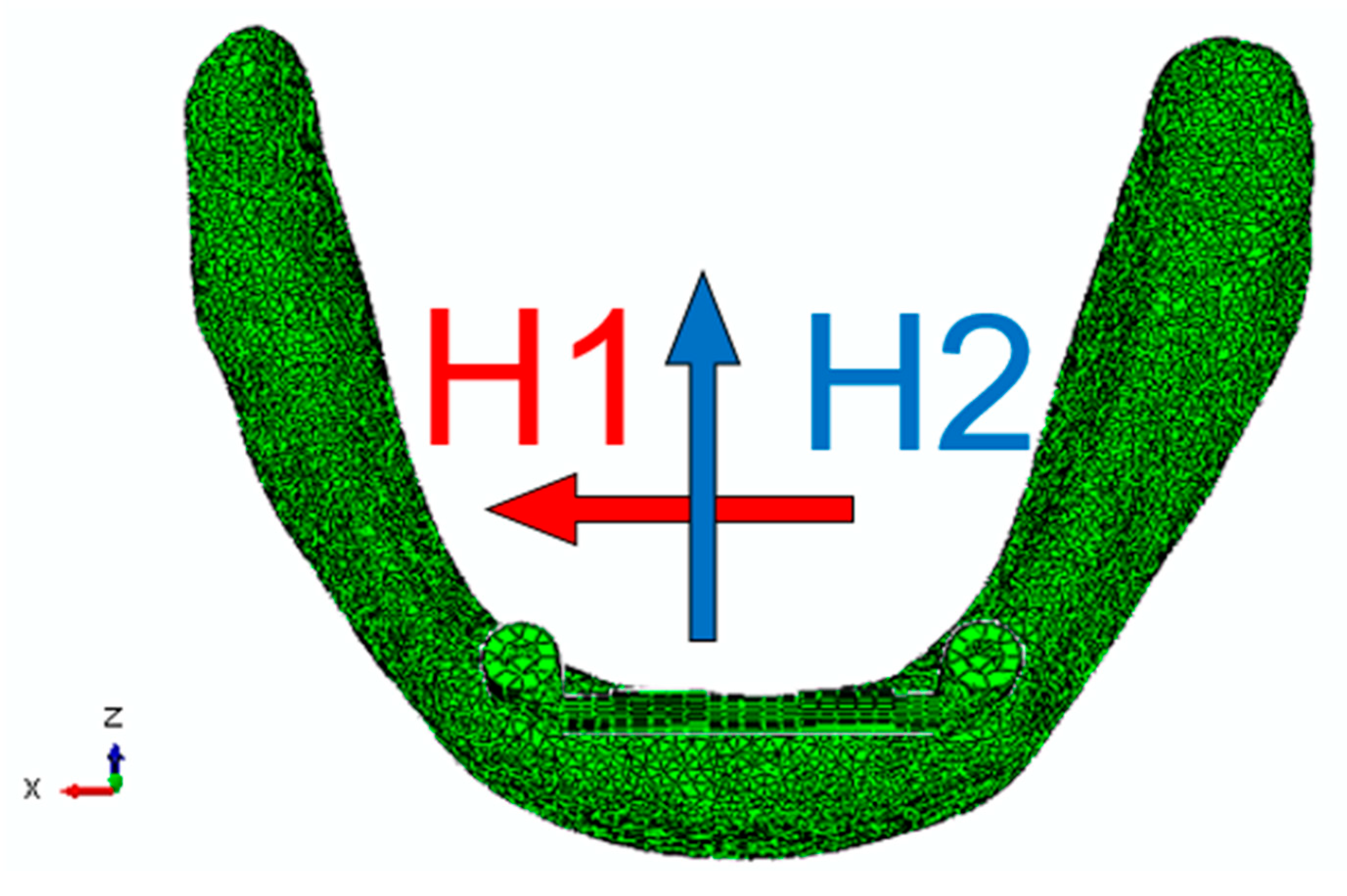
| Horizontal Force | Canine | Incisor | Molar |
|---|---|---|---|
| H1 X axis [N] | +0.095 | −0.037 | −0.071 |
| H2 Z axis [N] | −0.079 | +0.111 | −0.097 |
Publisher’s Note: MDPI stays neutral with regard to jurisdictional claims in published maps and institutional affiliations. |
© 2021 by the authors. Licensee MDPI, Basel, Switzerland. This article is an open access article distributed under the terms and conditions of the Creative Commons Attribution (CC BY) license (https://creativecommons.org/licenses/by/4.0/).
Share and Cite
Idzior-Haufa, M.; Pilarska, A.A.; Gajewski, T.; Szajek, K.; Faściszewski, Ł.; Boniecki, P.; Pilarski, K.; Łukaszewska-Kuska, M.; Dorocka-Bobkowska, B. Assessment of Contact Pressures between a Mandibular Overdenture and the Prosthodontic Area. Appl. Sci. 2021, 11, 4339. https://doi.org/10.3390/app11104339
Idzior-Haufa M, Pilarska AA, Gajewski T, Szajek K, Faściszewski Ł, Boniecki P, Pilarski K, Łukaszewska-Kuska M, Dorocka-Bobkowska B. Assessment of Contact Pressures between a Mandibular Overdenture and the Prosthodontic Area. Applied Sciences. 2021; 11(10):4339. https://doi.org/10.3390/app11104339
Chicago/Turabian StyleIdzior-Haufa, Małgorzata, Agnieszka A. Pilarska, Tomasz Gajewski, Krzysztof Szajek, Łukasz Faściszewski, Piotr Boniecki, Krzysztof Pilarski, Magdalena Łukaszewska-Kuska, and Barbara Dorocka-Bobkowska. 2021. "Assessment of Contact Pressures between a Mandibular Overdenture and the Prosthodontic Area" Applied Sciences 11, no. 10: 4339. https://doi.org/10.3390/app11104339